Next Article in Journal
Body Composition Changes of United States Smokejumpers during the 2017 Fire Season
Previous Article in Journal
The Impacts of Wildfire Characteristics and Employment on the Adaptive Management Strategies in the Intermountain West
 
 
Correction published on 18 January 2022, see Fire 2022, 5(1), 10.
Article

Winds and Gusts during the Thomas Fire

Department of Atmospheric and Environmental Sciences, University at Albany, SUNY, Albany, NY 12222, USA
*
Author to whom correspondence should be addressed.
Submission received: 22 October 2018 / Revised: 24 November 2018 / Accepted: 26 November 2018 / Published: 30 November 2018 / Corrected: 18 January 2022

Abstract

:
We analyze observed and simulated winds and gusts occurring before, during, and immediately after the ignition of the Thomas fire of December 2017. This fire started in Ventura county during a record-long Santa Ana wind event from two closely located but independent ignitions and grew to become (briefly) the largest by area burned in modern California history. Observations placed wind gusts as high as 35 m/s within 40 km of the ignition sites, but stations much closer to them reported much lower speeds. Our analysis of these records indicate these low wind reports (especially from cooperative “CWOP” stations) are neither reliable nor representative of conditions at the fire origin sites. Model simulations verified against available better quality observations indicate downslope wind conditions existed that placed the fastest winds on the lee slope locations where the fires are suspected to have started. A crude gust estimate suggests winds as fast as 32 m/s occurred at the time of the first fire origin, with higher speeds attained later.

Graphical Abstract

1. Introduction

The “Santa Ana” winds of Southern California are a very dry, sometimes hot, strong offshore flow that is most common during the September-May time frame [1,2,3,4,5,6]. These winds can also be locally fast as well as gusty, which means they can play a crucial role in starting and spreading fires and desiccating vegetation [7], substantially elevating the wildfire threat in the region [8,9]. Santa Ana winds have been involved in some of Southern California’s largest and/or most notorious wildfires, including the 1961 Bel Air fire, the Laguna fire of 1993, the 2003 Cedar and Old fires, and the Witch and Canyon fires in late October 2007, among numerous others. Episodes are typically characterized by high sea-level pressure (SLP) in the Great Basin along with a coastal trough, which establishes a pressure difference across the mountains between the Mojave Desert (see Figure 1) and the coast that has been used empirically to gauge the existence and persistence of offshore conditions [1,2]. Strong elevated (e.g., 700 hPa) temperature gradients and cold air advection have also been identified as significant event markers [5,10,11].
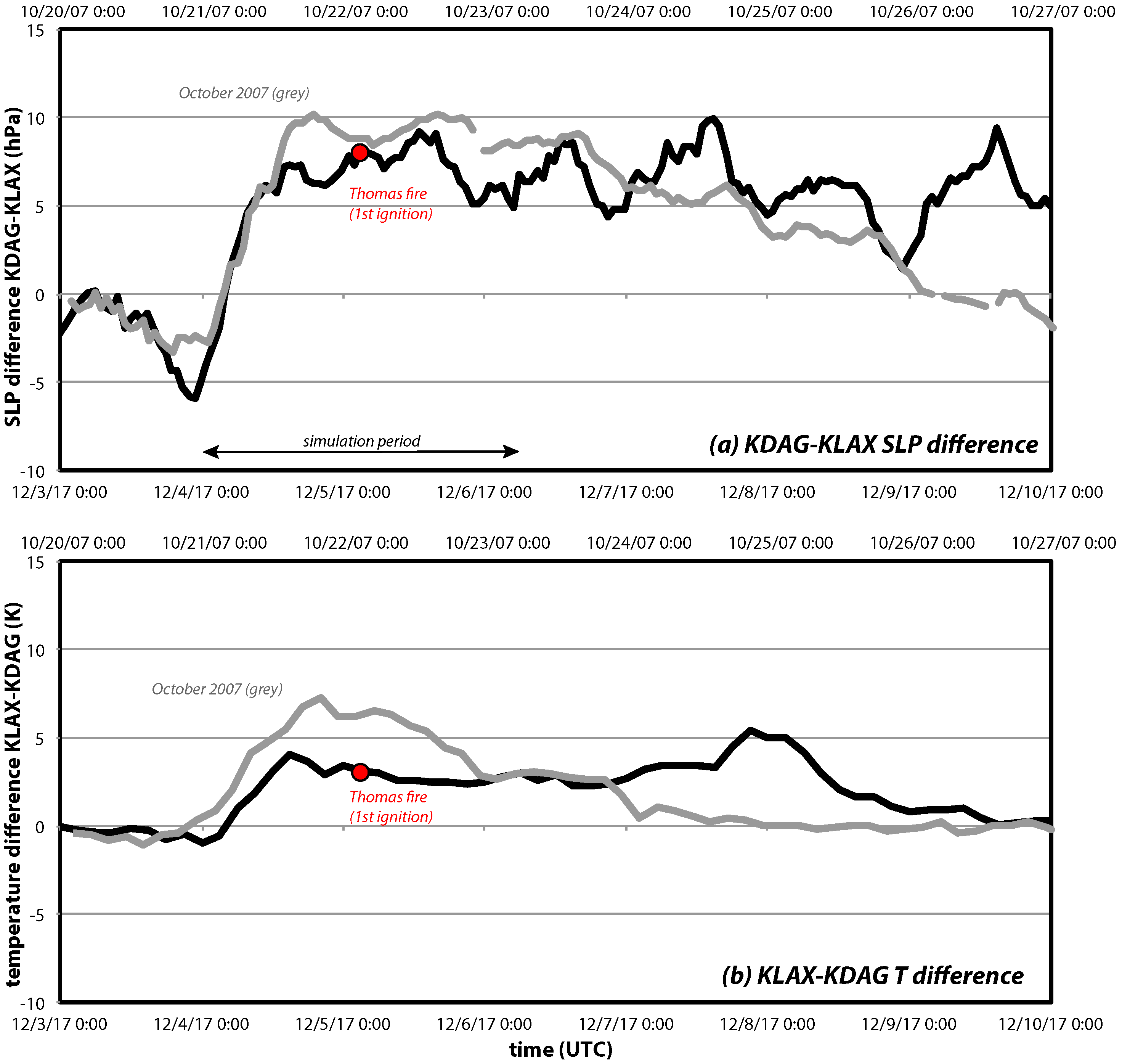
A Santa Ana wind event of exceptional temporal extent, unmatched in 70 years [12], started on 4 December 2017, quickly leading to the Thomas fire. [13] has discussed this episode’s synoptic setup and the extreme fire conditions present during this event. The SLP difference (ΔSLP) between Daggett (KDAG), located in the Mojave Desert, and Los Angeles International Airport (KLAX) became positive (Figure 1 and Figure 2a), indicating an offshore-directed pressure gradient. ΔSLP increased quickly thereafter, reaching 8 hPa by 0300 UTC on the 5th and peaking near 10 hPa during the time period depicted. The pressure differences did not become as large as during late October 2007 (grey curve), likely the strongest Santa Ana episode since November 1957, but remained positive for a longer period. The 700 hPa temperature difference between these points (Figure 2b), rendered as positive when the desert is colder, also suggests the December 2017 episode was less intense but more protracted.
According to public information sources available at this writing (http://cdfdata.fire.ca.gov/incidents/incidents_details_info?incident_id=1922), the Thomas Fire began prior to 0230 UTC 5 December (6:30 PM local daylight time on 4 December), just east of Steckel Park in Santa Paula, California, early within this extended episode. A separate fire subsequently started on Koenigstein Road, roughly 5 km northwest of the first ignition (https://www.independent.com/news/2017/dec/22/thomas-fire-had-two-origins/), (https://newsroom.edison.com/releases/sce-provides-an-update-on-the-circumstances-pertaining-to-the-2017-thomas-fire), which merged with the initial blaze during the first 24 h. Fanned by the persistently offshore flow, and exacerbated by serious drought conditions then present, the fire spread quickly across Ventura and Santa Barbara counties, becoming at the time the largest by area burned in modern California history (since 1932) [13]. By this writing, however, the Thomas fire size has already been surpassed by the Ranch Fire, part of 2018’s Mendocino Complex.
Our past studies of Santa Ana winds, which include [6,14,15] and used the Advanced Research version of the Weather Research and Forecasting (WRF-ARW) [16] model, were inspired directly or indirectly by their role in the wildfire threat. Those papers focused on San Diego county and verified wind predictions against observations from a dense mesonet installed by the San Diego Gas and Electric company (SDG & E), revealing model factors contributing to accurate wind and gust forecasts. The calibrated model setup was used to demonstrate the downslope windstorm nature of the Santa Ana winds during the Witch fire of October 2007 [14,17] and more recent episodes.
In this study, we examine winds and gusts associated with the Thomas fire, motivated by the suspicion that the near-surface observations recorded closest to the two ignition points were not representative of conditions present where the blazes started. We will show that the model can faithfully reproduce sustained winds recorded at stations located at airports and on mountain slopes deployed and maintained by government agencies and public utilities, justifying the use of these simulations in forensic and fire spread applications. However, the model exhibits a tendency to underpredict wind speeds at the most wind-favored locations and provides strong evidence that wind reports provided by private citizens are of relatively little value. We will also show that the Thomas fire ignition sites very likely experienced strong yet spatially confined downslope winds.
The structure of this paper is as follows. Section 2 describes the experimental design, including the model setup and sensitivity tests, and available observations. Section 3 presents the observations nearest the ignition sites, a critique of these reports, and verification of the control simulation against them. Forecasts for the ignition and neighboring observation sites and sensitivity experiments are presented in Section 4. The final section is composed of a summary and discussion of results.

2. Experimental Design

As in [6,14,15], the control simulation for this study employed the WRF-ARW (see abbreviations and acronyms list) model [16] using five nested domains with horizontal grid spacings of 54, 18, 6, 2, and 0.667 km, although the finest nest was shifted to cover the Thomas fire ignition points (Figure 3) and WRF version 3.7.1 was adopted (Table 1). Domain 4 (2-km resolution) encompassed nearly all of Southern California and all verifications against observations were performed in this nest. Two-way nesting was employed so information from finer nests was passed back to their parent domain(s). As in our previous studies, the 667-m nest was found to provide limited benefit but resolutions coarser than 2 km resulted in substantial wind overpredictions owing to improper terrain representation (not shown; see [6,15]).
The control configuration employed the Pleim-Xiu (PX) [18] land surface model (LSM) and Asymmetric Convection Model version 2 (ACM2) [19,20] planetary boundary layer (PBL) scheme owing to its superior wind forecasting performance [6,15]. The model top was 10 hPa with 50 layers (51 full-sigma vertical levels), using the default arrangement that focuses the highest resolution near the surface. The lowest horizontal wind level was roughly 26 m above ground level (AGL), so anemometer level winds (at 10 and 6.1 m) were computed using a stability-dependent logarithmic wind profile, as in [6,14,15]. Consistent with [6], we found shifting the lowest level down to 10 or 6.1 m had little effect on our results and none on our conclusions (not shown).
The control simulation was initialized with the analysis and forecasts from the NAM (see abbreviations and acronyms list) 12-km run of 0000 UTC 4 December 2017, approximately 26.5 h prior to Thomas fire ignition, and was integrated for 54 h. Options common to all runs shown herein included the RRTMG radiation scheme [21] and the MODIS land use database. A large number of other sensitivity tests were conducted, a subset of which are summarized in Table 1. Alternate initialization data sources included the GFS run of 0000 UTC 4 December 2017, the NAM run started 12 h later, hourly analyses from the 3-km HRRR [22], and the NARR reanalysis [23]. The perturbation experiments used WRF’s SKEBS approach [15,24]. Other physics combinations employed the YSU [25], Shin-Hong [26], and MYNN2 [27] PBL schemes and the Noah LSM [28], without and with (“Noah z_0mod”) roughness length modifications described in [15]. As in [6,15], the LSM had by far the largest influence on wind forecasting skill. WRF version 3.9.1.1 was adopted for the MYNN2 runs to exploit recent scheme improvements; a run with PX/ACM2 was also made with this version, with only minimal differences from the control run being noted. Owing to its more limited spatial coverage, the HRRR-initialized simulation used a reconfigured domain (Table 1).
Verification of model wind forecasts were performed against sustained wind observations from the sources listed in Table 2, which includes the ASOS, AWOS, RAWS, SDG & E, and CWOP networks (see also Figure 1). ASOS and AWOS stations are located primarily at airports, RAWS installations favor west- and south-facing mountain slopes, the SDG & E sites are concentrated in San Diego county, and the CWOP observations are contributed by private citizens. These data were obtained from MADIS and (for ASOS) supplemented from the 1-min archive at NCEI, for reasons discussed presently. Anemometer heights are 10 m AGL for most (if not all) ASOS and AWOS stations, and 6.1 m AGL for RAWS and SDG & E installations. For CWOP stations, anemometers are often secured near residences and obstructions, at unknown heights, and may also use lower quality equipment [29], but were presumed to be 10 m AGL for simplicity; this assumption is assessed later. Modern ASOS stations employ sonic anemometers, while other networks may also use cup- and propeller-based units in whole or in part.

3. Survey of Observations and Verification of Model Forecasts

3.1. Wind and Gust Observations Near the Thomas Fire Ignition Sites

As noted above, we are aware of two independent ignitions on December 5th that combined to create the Thomas fire. For the purposes of this study, the first ignition was assumed to have occurred at 0220 UTC at the location marked by red star “1” on Figure 4, which shows the topography of 667-m Domain 5. Our principal focus will be on conditions at and near this site. The presumed site of the second ignition is identified as red star “2”. This information was derived from California Department of Forestry and Fire Protection (CAL FIRE) reports and maps and various news articles, and is considered sufficiently accurate and precise for the present study.
Most stations report both (sustained) winds and some measure of peak wind or gust. Anemometers aggregate raw observations into samples of specified length (such as 3 s, the WMO standard [30]), and then average those samples over certain time intervals to yield the sustained wind. This sampling length varies among networks and can influence the reported winds and gusts. While the averaging interval also varies, ranging from 2 min for ASOS and AWOS to 10 min for RAWS and SDG & E, these sustained wind reports “are all equivalent measures of the true mean wind but with differing variance” [31]. The gust is nominally the fastest sample during the averaging interval, but this depends on how the data are handled. For RAWS, which report hourly, the gust is the peak wind recorded since the previous transmission [15]. ASOS and AWOS data from MADIS use complex METAR reporting rules [32] that (in the United States) zero out light (<1.5 m/s) winds and seriously compromise the gust record [33]. We will employ raw ASOS winds and gusts from the 1-min database and augment them with METAR-filtered information only when necessary.
The markers on Figure 4 indicate the network affiliation of available observation stations in Domain 5, color coded by the fastest gust reported during the simulation period (0000 UTC 4 December to 0600 UTC 6 December 2017). The highest values during this interval were from CWOP stations F0112 and D5145 (35.3 and 34.0 m/s), both located near the coast, south-southeast of the Thomas fire ignitions. At F0112, winds and gusts ramped up quickly in the hours prior to the first fire start (Figure 5a). In the D5145 record (not shown), a data gap occurred on 5 December between 0617 and 1639 UTC, during which time even stronger winds could have occurred. Gusts exceeding 30 m/s also were recorded at CWOP station AT184, 10 km south-southeast of the first ignition site, and at RAWS and ASOS sites WLYC1 and KNTD, respectively (see Figure 4). Winds at AT184 and WLYC1 (Figure 5b,c) picked up earlier than at coastal stations F0112 and KNTD (Figure 5a,d), and were quite variable at AT184 after the fire onset time.
In contrast, gust reports from the stations nearest the two fire sites – D7412, AT490, C7664, and E7495 – are not remarkably fast (Figure 4), and sustained winds were very light (Figure 6a–c). These were all CWOP stations. At D7412, only 3 km south of our estimated earlier ignition point, winds and gusts topped out at 7.2 (Figure 6a) and 12.5 m/s, respectively, prior to reports pausing after 0502 UTC on 5 December. Even lower winds were recorded at nearby AT490 and C7664 (Figure 6b). At E4795, only 2 km southwest of ignition site #2, the highest wind (Figure 6c) and gust readings (6 and 11.1 m/s) came in the station’s final communication at 0542 UTC 5 December. (Station D7412 resumed reporting after the time period of interest, while E7495 has still not returned as of this writing.)
Based on these CWOP reports, it might be concluded that the winds near the two Thomas fire ignition points were not very strong. This study will argue that these particular stations were likely quite obstructed and, even if not, were unrepresentative of winds at the fire sites, despite their proximity.

3.2. Evaluation of Observations

Every network may have problem sites, with particularly large data and/or exposure issues. We attempt to identify these using the station gust factor (GF), the ratio of the gust and sustained winds. Obstructions influence gusts less significantly than sustained winds [30], so large GFs may reflect substantial exposure restrictions. For every site, a GF was computed from the averages of all reasonable wind-gust pairs available during the simulation period. Since the GF is sensitive to the sampling length, averaging interval, and mounting height [34,35,36], typical values will vary among networks, so sites are evaluated relative to their network’s average. GF also generally decreases with increasing sustained wind [14,35]. (As gust information for AWOS stations is compromised by METAR reporting rules, this network is not examined.)
Station mean GFs, in rank order for each network, are shown in Figure 7. For ASOS stations, the average GF was 1.24, with the largest value (1.60) at KCQT, a non-airport station near downtown Los Angeles. This site is relatively obstructed but retention did not materially alter the results or conclusions. For SDG & E, the average GF was 1.72 and highest value (2.63) occurred at a station (MLG) closely surrounded by trees (cf. [14]). The network mean (2.26) and variation among the RAWS sites were both large, with values as high as 5.1 (at ARGC1, a heavily obstructed site). We elected to remove the 9 stations with GFs > 3 along with three sites misclassified as being over water by the model (which included LCBC1, seen on the coast in Figure 4), leaving 66 stations for analysis (Table 2). As those sites also tended to have exceptionally large forecast wind biases, their exclusion reduced the network- and event-averaged bias by 69% (from 0.70 to 0.22 m/s).
Of the 421 CWOP sites (Figure 7b), 404 reported non-zero sustained winds at any time during the simulation period and even fewer (359) had gust information useful for this analysis. Still, some stations had suspiciously low sustained winds and, as a consequence, had exceptionally large station GFs (as high as 29.33). That said, retaining the sites with GFs > 6, about 9% of the total, made almost no difference to the results reported below. It will be seen that restricting the analysis to observations passing the highest quality control level (QC3) also had little effect on the results.

3.3. Control Simulation and Forecast Verification

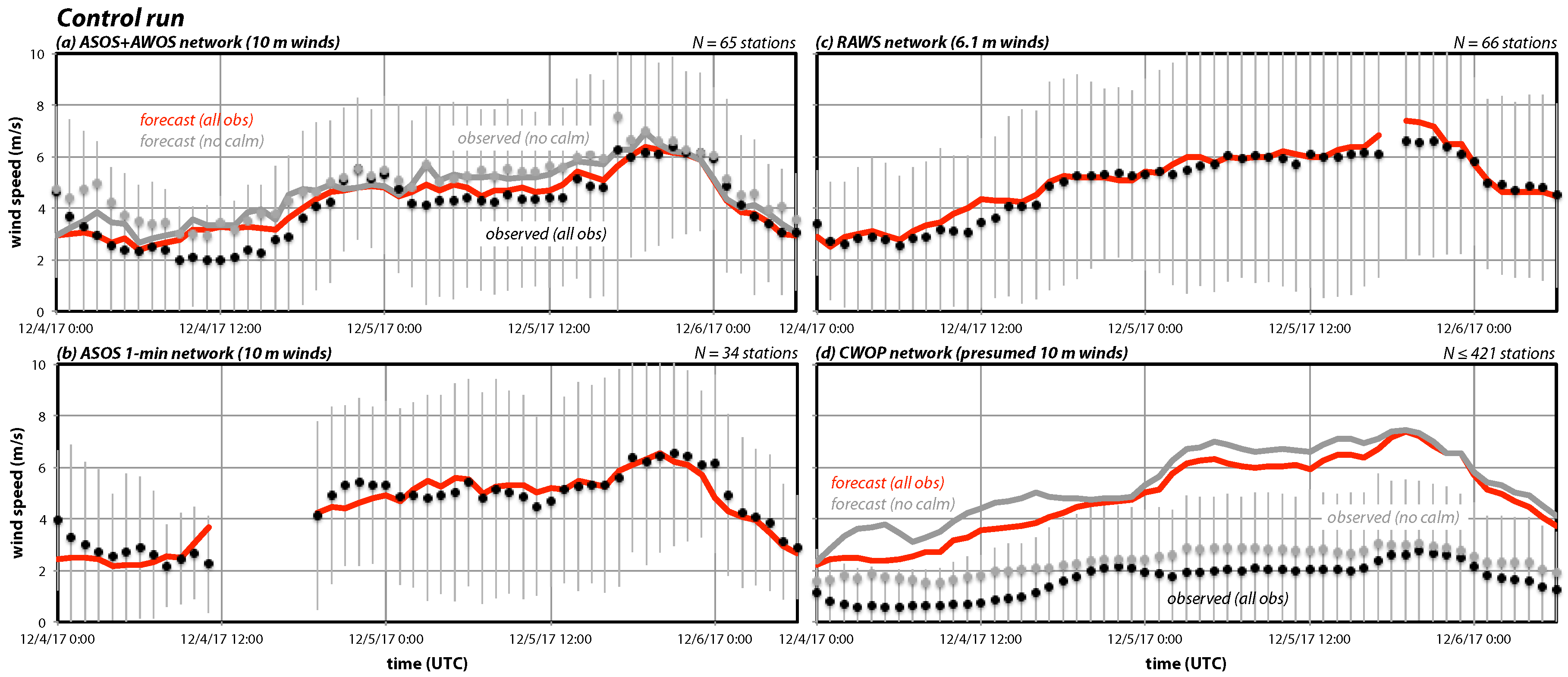
As described above, the control simulation was initialized from NAM at 0000 UTC 4 December 2017. As in [6], hourly comparisons with sustained wind observations were accomplished using the Developmental Testbed Center’s MET software using 10 m wind forecasts adjusted to the appropriate anemometer height as needed. Of the 724 stations shown on Figure 4, about 9% (N = 65) are airport-dominated ASOS and AWOS stations. Figure 8a shows forecasts (red curve) and METAR-derived observations (black dots) averaged over these sites, along with ±1 standard deviation of the observations. Overall, the network-averaged reconstruction is quite good, although the bias is positive during the first 18 h, which incorporates the nighttime and early morning hours of the first simulated diurnal period.
Our experience is that even well-calibrated models tend to overforecast 10 m winds overnight during synoptically quiet periods, but this high bias was exacerbated by the METAR reporting rules. The zeroing of slower winds resulted in a fairly large fraction (19%; see Table 2) of calm reports. In contrast, only 5% of the corresponding forecasts were very slow (defined here as <0.5 m/s, generally the smallest non-zero wind speed available from non-METAR filtered records). For the subset of 34 ASOS stations alone (non-filtered AWOS data not being available), METAR filtering forced 23% of all observations to be exactly zero, although only 1% of the raw 1-min reports were actually calm (Table 2). When calm METAR observations were excluded (shown in grey in Figure 8a), forecast fidelity was even higher, especially during the nighttime hours of the first simulated day. (Conditions were windier on the second night, and less adversely affected by METAR filtering, because by that time the Santa Ana event was well underway.).
Figure 8b shows network-averaged winds from the 1-min database for the 34 ASOS stations. This source often has gaps, as occurred on 4 December before the Santa Ana event started in earnest, but the reconstruction for the available time period is clearly very good. The model forecast winds (adjusted to 6.1 m AGL) for the RAWS (Figure 8c) and SDG & E networks (not shown) were also judged skillful. Other factors being equal, RAWS winds could be higher than those recorded at airports, especially during Santa Ana events, owing to their preferential siting on mountain slopes, even though their anemometers are mounted closer to the ground and are generally installed in rougher terrain and amidst taller vegetation. During the present period, the RAWS network-averaged wind exceeded the ASOS value by about 10%.
In aggregate, the model overpredicts winds at the 421 CWOP stations by a factor of almost 3 (Figure 8d). While a few sites (e.g., F0112 and AT184) experienced strong winds, the vast majority of stations reported very low wind speeds. Fully 39% of the CWOP observations during this period were exactly calm (Table 2), even though no METAR-like filtering was employed. (Among the CWOP records, the smallest non-zero wind speed was 0.45 m/s = 1 mph, which is typical of non-filtered data, whereas METAR zeroed observations below about 1.5 m/s).
This enormous bias is believed to be the consequence of extreme exposure issues that characterize the network as a whole. As noted earlier, many CWOP stations are installed in private backyards, likely too close to buildings and trees, and their anemometers are not guaranteed to be mounted at 10 or even 6.1 m AGL. (Note that presuming a 6.1 m height reduces the huge positive bias only by 19%, which does not substantially address the problem). Furthermore, while exclusion of the calm observations (shown in grey) increased the mean observed and forecasted winds, the bias did not change much. That comparison also only retained observations given the highest quality control (QC) rating (level 3); by itself, this made very little difference. The quality control information provided by MADIS cannot be relied upon to identify heavily obstructed sites.
The central problem here is that the same model that exhibits a high amount of skill in forecasting the all-station wind for ASOS and other networks winds has an extremely large bias over all CWOP sites. This is further demonstrated in Figure 9, which compares forecasts and observations between the ASOS/AWOS and CWOP networks. Each dot represents an hourly average between forecast hours 12 and 54, inclusive. The correlation between the airport and CWOP network averages (black dots) is very high (r = 0.95) but the slope is about 2.4, as the ASOS/AWOS sites invariably reported substantially higher wind speeds. Forecasts for these two networks (red dots) were also highly correlated (r = 0.9) but the model actually predicted higher network-averaged winds for the CWOP stations. In contrast to the airport sites, CWOP installations were somewhat more likely to be sited in wind corridors, places where the model predicted higher near-surface wind speeds. Exclusion of calm and/or lower quality CWOP observations (resulting in the grey and orange comparisons) did not mitigate this problem.
Thus, it must be concluded that, as a group, the CWOP winds were likely compromised by exposure or other instrument issues, that using these observations for verifying model forecasts is not appropriate, and that the model cannot be expected to reconstruct the network-averaged wind without substantial bias correction. It is noted that other recent studies [37,38,39,40] have found pressure, temperature or moisture observations from non-conventional networks (such as CWOP) to be of value, but typically not their wind reports. In any event, the effective height of their anemometers is likely much lower than 10 m and the presence of significant obstacles renders the application of the logarithmic wind profile problematic anyway [41].
Using SDG & E observations taken during Santa Ana episodes, [6,15] demonstrated that even when the network-averaged sustained wind was reasonably well reproduced, the model tended to systematically underpredict at windier locations and overforecast less windy sites. In other words, the forecast bias was itself biased, and that occurred in all model configurations. A similar result transpired in the control simulation among the airport, RAWS, and SDG & E stations (Figure 10). Taken as a group, the bias for these three networks’ 291 unique stations was normally distributed about a mean of about 0.3 m/s, and the correlation with the observed sustained wind was −0.7, indicating a strong tendency to underspecify locations with higher mean wind speeds. The CWOP network was excluded (Figure 10c) because only about 2% of its 421 stations were underpredicted. (AT490 and C7664, in fact, were the 3rd and 6th most overpredicted stations, with D7412 and E4705 ranking 45th and 105th, respectively.) [15] further demonstrated that the forecast wind bias was predictable from the station GF, which was interpreted as indicative of exposure. While this held true in the present study (not shown), the main point here is that based on these results we can reasonably anticipate underpredicting speeds in wind-favored areas where observations are lacking.

4. Model Predicted Winds at and Near the Fire Sites

The control run’s near-surface sustained winds have compared well with available station data of reasonable quality (which excludes most CWOP sites) albeit with a tendency to underpredict speeds at windier locations. In this section, we examine forecasts at and near the suspected ignition points and also examine vertical cross sections aligned with the wind that cross those points.

4.1. Forecasts for the Ignition Sites and Nearby Stations

Figure 5 also shows control run sustained wind forecasts (red curves) for some of the windier locations near the Thomas fire sites. Over the event, the biases at CWOP stations F0112 and AT184, and ASOS site KNTD, were close to zero (Figure 10a,c). The onset of stronger winds at AT184 was well captured (Figure 5b) but the subsequent variability was not, particularly the occasional periods in which the winds subsided. At coastal F0112 (Figure 4), the predicted winds ramped up a few hours too early but then were underpredicted somewhat once the event was underway (Figure 5a). A similar situation occurred at nearby ASOS station KNTD (Figure 5d). Thus, the model appears to have brought the higher winds to the coast somewhat too quickly. The forecasted wind evolution at inland RAWS station WLYC1 was reasonable (Figure 5b) but represented that network’s 2nd most underpredicted site (Figure 10b). Please note that the strongest sustained winds were not captured at any of those locations.
As mentioned earlier, observed sustained winds at CWOP site D7412, located just 3 km south of ignition site # 1, peaked at 7.2 m/s (Figure 6a). In contrast, the model (red curve) predicted winds as high as 13 m/s during the period the station was active, subsequently reaching 14 m/s. Wind reports at D7412 were exactly zero 34% of the time, close to the network average (Table 2). We are compelled to conclude that the observed winds there were not representative of the general area. Also shown (blue curve) are forecasted sustained winds at the ignition site #1, which peaked at 19.3 m/s shortly after the fire started. Even if the speeds in the vicinity of D7412 had been as predicted, note the winds at the fire initiation point were probably faster still. Predicted winds at ignition site #2 (Figure 6c) also generally exceeded those prognosed for nearby CWOP site E4795. That station’s observations, which were calm 62% of the time, are unhelpful in understanding conditions at the time of the second fire.

4.2. Vertical Cross-Sections Past the Ignition Points

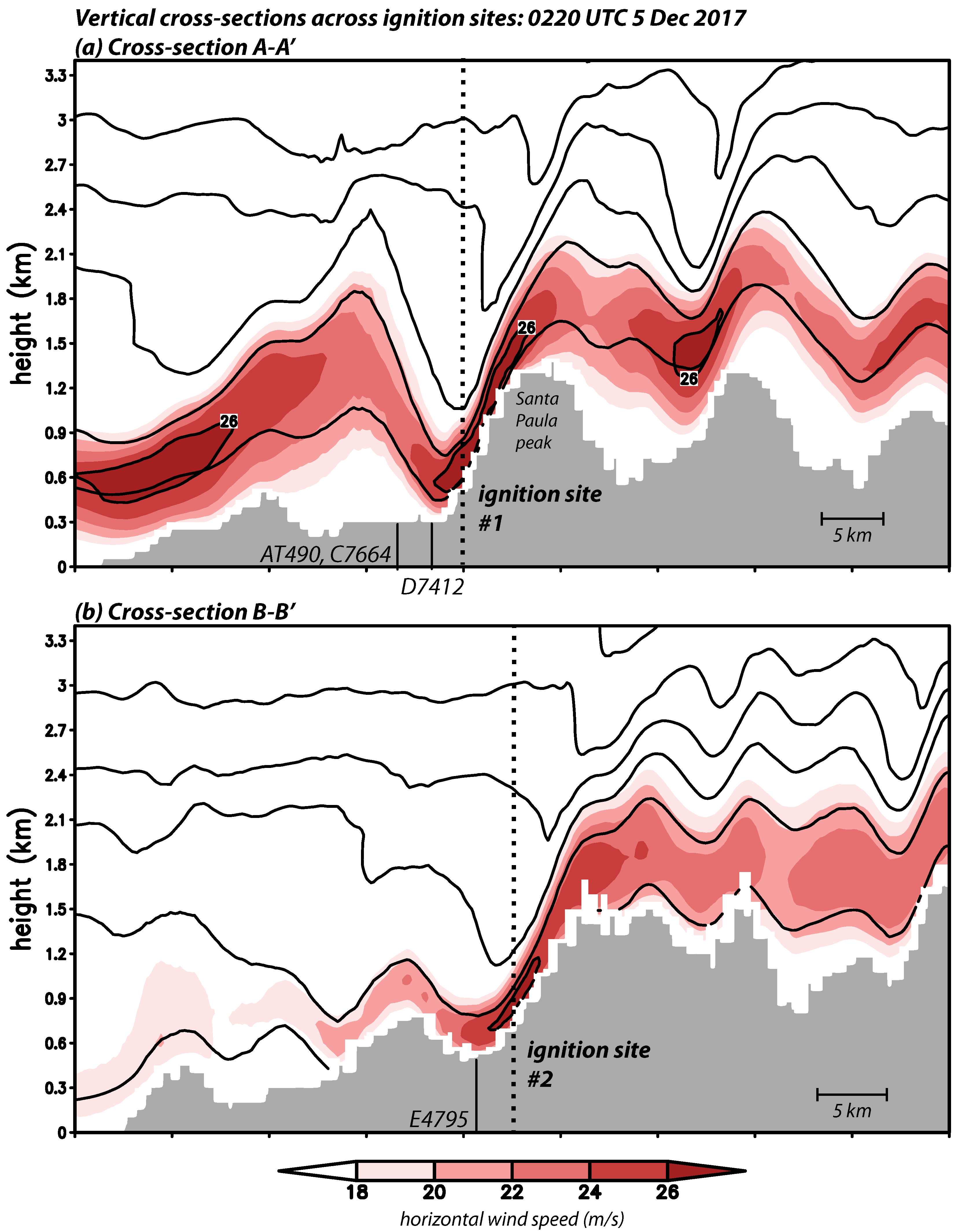
Figure 11 presents vertical cross-sections of horizontal wind speed (shaded) and potential temperature (contoured) oriented southwest to northeast, roughly in the direction of the winds, crossing over the two ignition sites. Contours of potential temperature (known as isentropes) are analogous to streamlines since, in the absence of water phase change, potential temperature is approximately conserved, and their vertical spacing is inversely proportional to atmospheric stability. The time shown is 0220 UTC on 5 December, presumed to be the first ignition time. In both sections, a roughly 500 m thick ribbon of higher velocity air (moving from right to left) is seen, remaining elevated before reaching the last sizable peak (that being Santa Paula mountain in Figure 11a) prior to reaching the coast. At that point, the isentropes drop sharply downward, indicating descending motion, and fast wind speeds reach to or very near the surface, with maximum speeds coinciding almost precisely with the fire origins. There is little change in the airflow between this time and the onset time of fire #2, the only difference being the strong winds extend a little farther downslope.
Just downwind of ignition site #1 (Figure 11a), the winds lofted before reaching the nearby CWOP sites (which are also slightly out of the plane shown; see Figure 4). This helps illustrate why the ignition site predictions exceeded those from even the nearest surface stations (Figure 6a). Please note that, at this time, only a small portion of the surface revealed in this cross-section would have experienced sizable winds. In the second section, the descended downslope flow followed the surface somewhat farther downwind, although through an area lacking surface stations (Figure 4). It should be noted that, at both fire sites, strong winds were present very close to the surface, and might be easily transported downward by turbulent motions that the model cannot resolve owing to its spatial and temporal scales, and this will be exploited to provide a crude gust estimate shortly.
The evolution of the winds in the vertical cross-section passing ignition site #1 is shown in Figure 12. One favorable configuration for downslope winds is a layer of larger stability beneath a less stable one [42,43] or the presence of an elevated inversion [44]. In the hours before the first ignition (Figure 12a,b), an elevated layer of relatively higher stability (indicated by a closer vertical isentrope spacing) was present and air was subsiding on the lee side of Santa Paula peak. However, the flow was not yet strong in this area, and relatively little amplification of the wind on the lee side of Santa Paula peak occurred until faster-moving air moved in from the northeast. Subsequent to the fire onset time (Figure 12d–f), lower tropospheric winds increased, especially downstream of Santa Paula peak, but flow velocities remained significantly faster immediately above the ignition site relative to those at the CWOP stations farther downslope.
Winds upstream of Santa Paula peak fluctuated as the high wind ribbon moved vertically (and also horizontally; not shown) with time. RAWS station WTPC1 is located northeast of the ignition sites (Figure 4), and positioned near the right end of the Figure 12 cross-section, albeit slightly out of the plane. Over the event, WTPC1’s sustained winds were underpredicted (Figure 10b) but the evolution of the winds there were captured qualitatively by the control run. (At times during the event, WTPC1’s reported sustained winds were more comparable to the model’s forecasts at the lowest horizontal wind level [26 m], also shown on Figure 6d.) Wind speeds were observed to increase between the times marked (d) and (e) on Figure 6d, which correspond to panels on Figure 12. During that interval, the simulation shows the high wind ribbon descended towards the surface, with strongest winds located directly above the RAWS site. Between times (e) and (f), however, wind speeds decreased at the site. In the model, that coincided with the high wind ribbon shifting back upward (Figure 12f).

4.3. Sensitivity Tests and Near-Surface Winds above the First Ignition Site

Downslope windstorms can be very sensitive to variations in environmental conditions, model physics, and even random perturbations [6,15,42,45,46], so an assessment of the robustness of the control run’s airflow characteristics (including magnitude) is warranted. Figure 13 shows cross sections spanning ignition site #1 at 0220 UTC 5 December, for comparison with Figure 11a, from a subset of the sensitivity experiments listed on Table 1. The SKEBS scheme [24] generates perturbations for the potential temperature field and rotational components of the horizontal wind, controlled by a random number seed, and Figure 13a shows the average of five trials. In [15], the development and positioning of a hydraulic jump-like feature on a lee slope in San Diego county was found to be sensitive to perturbations. In this case, however, the perturbations had little effect and so the flow remained very similar to that of the control run.
Figure 13b,c show the cross-sections from runs with different PBL schemes (MYNN2 and YSU), both employing the aforementioned Noah z_0mod LSM. As noted earlier, [15] found wind forecast skill improved when the Noah parameterization was modified to use the (generally larger) roughness lengths presumed by the standard configuration’s PX scheme. The airflows produced by these simulations at this time are very similar to the control run’s, with somewhat stronger winds on Santa Paula peak’s lee slope. Other PBL schemes tested (Shin-Hong and MYJ) also produced slightly higher winds (not shown). A simulation pairing YSU with the original, unmodified version of Noah (Figure 13d) reveals a similar airflow pattern but with stronger winds almost everywhere, including close to the surface. Consistent with previous work, unmodified Noah runs were found to considerably overpredict the winds at airport, RAWS, and SDG & E sites (not shown).
The remaining panels (Figure 13e–h) show results using different initializations with the control run’s physics configuration. The airflow is quite similar in all four, with the fastest winds remaining immediately over the ignition site. Starting with the NAM run from 12 h later placed winds of comparable strength at the fire site as the control. The GFS and HRRR initialized runs generated slightly weaker winds than the control simulation at this time while the NARR’s were a little stronger. These differences remain well within any reasonable range of uncertainty.
During the downslope wind event, the strongest flow above the ignition site(s) appeared close to the surface, and as noted above it is easy to imagine those higher velocities could become transported downward by unresolved turbulent motions. This motivates a simple gust measure, dubbed NSMAX (for near-surface maximum) by [14], which here consists of the fastest resolved-scale horizontal wind within the lowest ≈600 m. This depth was selected empirically to capture the strongest winds present in the near-surface layer during downslope flow conditions on susceptible slopes. This measure will certainly overestimate gusts during periods at which the flow is weak and/or turbulence is not anticipated but could also be expected to underestimate them during windier periods as no further amplification of the flow by turbulence is considered and vertical motions are neglected. Furthermore, note that the cause of at least ignition #1 is presently not known to us, and could have involved winds at a higher altitude (e.g., at canopy height) than standard anemometer level anyway. Thus, NSMAX provides insight into what the model is producing with respect to winds immediately above a particular location.
Figure 14 presents a time series of the NSMAX gust estimate for the initial fire site. Along with the control run (black curve), values from an ensemble of 15 simulations are superposed, being those included on Table 1 (excluding the unmodified Noah run owing to its overpredictions of anemometer-level winds). In all simulations, NSMAX values ramped up in two phases, corresponding to the initial onset and subsequent intensification of the offshore flow in the vicinity of the Thomas fire, and remained strong after the fire start time. Also shown (in grey) is the standard deviation among these simulations, as a measure of uncertainty. That measure peaks briefly prior to 1200 UTC 4 December, reflecting some variation in offshore wind onset timing, but the range of gust estimates (27–32 m/s) around the first fire’s onset time is fairly small and larger differences among the ensemble members do not emerge until after 1800 UTC 5 December. It should be noted that we are not attempting to incorporate the direct and indirect effects of the fires into these simulations.

5. Discussion

Southern California’s Santa Ana wind is an offshore flow commonly occurring between September and May [2,4] when high pressure builds over the Great Basin [1,10]. High wind speeds in favored areas can combine with very low humidity to create a significant wildfire threat, especially when the vegetation is dry [9]. Indeed, many of the region’s most significant wildfires have started during offshore wind events [8]. As an example, the Thomas fire, which was the largest of California’s many blazes in the last century on its date of containment, began near the start of the longest Santa Ana wind event since at least 1948 [12].
As winds were likely involved in the start and/or spread of the fire, sustained (e.g., time-averaged) and gust (instantaneous) wind speeds at and near the Thomas fire origins, both leading up to and immediately following the ignitions, are of interest. During the 48 h period bracketing the ignitions, wind gusts as high as 35 m/s (79 mph) were reported within about 40 km of the origins, both of which were located near Santa Paula in Ventura county. Many of the higher wind reports came from ASOS/AWOS and RAWS stations, which are operated by federal or state authorities and located typically at airports and on mountain slopes, respectively. Curiously, however, the stations closest to the ignition sites reported much smaller gusts, not exceeding 12.5 m/s (28 mph). These were CWOP sites, contributed by private citizens.
Because the Santa Ana winds exhibit characteristics of both gap flows and downslope windstorms [5,6], wind speeds would be expected to vary greatly in both space and time anyway, making the direct use of even nearby wind observations as a proxy for conditions at the ignition site(s) problematic. As a consequence, we employed the WRF-ARW model, configured similarly as [6,14,15], to estimate sustained wind speeds at and near the Thomas fire ignition locations and times. The cited studies demonstrated the model’s skill in reproducing winds averaged across the SDG & E mesonet in San Diego county during a variety of past recent events, highlighting assumptions regarding surface roughness as a critical factor in forecast success. Forecast sustained wind biases were shown to be negatively correlated with observed wind speeds, which [15] showed were predictable from observed gust behavior, quantified as the gust factor, the ratio of observed gust and sustained wind reports. However, the main point is that while in the mean the model predictions were skillful, speeds at windier locations were consistently underpredicted.
For a roughly 2-day period spanning the Thomas fire onsets, we demonstrated that the model provided skillful reconstructions of the network-averaged winds for the ASOS, RAWS, and SDG & E networks, although (as in past work) it tended to underpredict speeds at windier sites. Simultaneously, it substantially overpredicted the CWOP winds, especially for the stations nearest the ignition sites. We showed that the CWOP sites tended to provide a suspiciously large percentage of calm sustained wind reports and have large to very large gust factors, both possibly indicators of moderate to severe anemometer placement issues. This led us to question the validity of the CWOP network wind observations for model verification and their applicability to wind conditions at the ignition sites.
Vertical cross-sections were used to examine the airflow as it impacted the presumed Thomas fire ignition sites, with special emphasis on the the first. The model generated a fairly typical downslope windstorm with the strongest flow speeds located very near the surface on the lee slope, coincident with the ignition sites, coupled with a jump-like feature that lofted the strongest flow over surface sites located farther downstream of site #1. Flow intensity rapidly increased shortly before the first ignition time and remained strong during the simulation period, but with undulations in the high-wind “ribbon” that at least qualitatively resembled patterns observed in near-surface winds. Sensitivity testing revealed that the wind speeds at, near, and above the initial ignition location were largely insensitive to the introduction of random perturbations and changing the initialization time, data source, and/or model physics (other than the land surface model). Using the fastest wind speed in the lowest ≈600 m as a crude gust proxy, we find estimates of 29 ± 1.4 m/s (65 ± 3.1 mph) for instantaneous wind speeds at the first origin site, valid for the presumed ignition time. It is noted that no attempt was made to incorporate the fire heat sources and we again caution that the model tends to underspecify wind speeds at windier locations, which certainly appears to be applicable to the Thomas fire ignition points.

6. Conclusions

We have examined winds at and near the Thomas fire origin sites, with an emphasis on the first ignition location and time, critically evaluating available observational data and numerical simulations. Our study demonstrates the strengths and weaknesses of using well-calibrated and verified numerical models for real-time forecasting, fire spread modeling, and fire management decision-making, as well as for forensic reconstruction of conditions existing at ignition points. It also highlights important issues regarding the representativeness of surface wind and gust observations. Our principal findings are:
  • The Thomas fire ignition sites, especially the primary origin, were likely subjected to strong but quite localized near-surface winds due to the downsloping flow being elevated both farther upwind and downwind, the latter having the form of a hydraulic jump. Owing to this, even reliable nearby surface stations might have failed to capture the true magnitude of the winds and gusts occurring at the ignition sites, leaving properly verified numerical model simulations as a viable tool for estimating flow conditions at and above the fire sites.
  • The numerical model provided skillful reconstructions of the network-averaged sustained winds for ASOS, RAWS, and SDG & E surface stations while at the same time severely overpredicting winds for the cooperative citizen weather observing (CWOP) network, even after calm reports were neglected and quality control filtering was applied. Thus, the validity of CWOP wind reports as a group was questioned and the recommendation made that these stations be treated with suspicion and excluded from model verifications.
  • The modeling results were shown to be largely insensitive to the introduction of random perturbations and other alterations (apart from changing the land surface model, which determines surface roughness). Using a crude estimate, the simulations suggested that gusts reached at least 29 ± 1.4 m/s (65 ± 3.1 mph) at the first origin site for the presumed ignition time, with higher speeds predicted later.
  • However, as we provided evidence that well-calibrated models tend to consistently underspecify wind speeds at windier locations, and since the gust proxy did not attempt to account for additional momentum production by turbulence, this gust estimate should be treated as a lower bound. We suspect that instantaneous wind speeds experienced at the ignition sites were substantially higher at the times the fires started.

Author Contributions

Conceptualization, R.F.; Data curation, A.G.; Formal analysis, R.F. and A.G.; Funding acquisition, R.F.; Methodology, R.F.; Writing-original draft, R.F. and A.G.; Writing-review and editing, R.F. and A.G.

Funding

This research was supported by National Science Foundation grant 1450195.

Acknowledgments

WRF-ARW is maintained at NCAR (www.mmm.ucar.edu/weather-research-and-forecasting-model). Model Evaluation Tools (MET) software was developed by the Development Testbed Center (dtcenter.org). HRRR grids were obtained from Brian Blaylock’s archive at the University of Utah (doi:10.7278/S5JQ0Z5B). Other data used during this research were acquired from MADIS (madis-data.ncep.noaa.gov), NCEI (www.ncei.noaa.gov), the Big Weather Web (bigweatherweb.org), and the NCAR Research Data Archive (rda.ucar.edu). The authors thank four anonymous reviewers for their constructive suggestions.

Conflicts of Interest

The authors declare no conflict of interest.

Abbreviations

The following abbreviations and acronyms are used in this manuscript:
ACM2Asymmetric Convection Model version 2 PBL scheme
AGLAbove ground level
ARWAdvanced Research WRF core
ASOSAutomated Surface Observing System
AWOSAutomated Weather Observing System
CWOPCitizen Weather Observing Program
GFGust factor
GFSGlobal Forecast System
HRRRHigh-Resolution Rapid Refresh
MADISMeteorological Assimilation Data Ingest System
METModel Evaluation Tools
METARMeteorological Terminal Aviation Routine Weather Report
MODISModerate Resolution Imaging Spectroradiometer
MYNN2Mellor-Yamada-Nakanishi-Niino level 2
NCARNational Center for Atmospheric Research
NCEINational Centers for Environmental Information
NAMNorth American Mesoscale
NARRNorth American Regional Reanalysis
PBLPlanetary boundary layer
QCQuality control
RAWSRemote Automated Weather Stations
RRTMGRapid Radiative Transfer Model for General Circulation Models
SDG & ESan Diego Gas and Electric
SKEBSStochastic Kinetic Energy Backscatter Scheme
WMOWorld Meteorological Organization
WRFWeather Research and Forecasting
YSUYonsei University

References

  1. Sommers, W.T. LFM forecast variables related to Santa Ana wind occurrences. Mon. Weather Rev. 1978, 106, 1307–1316. [Google Scholar] [CrossRef]
  2. Raphael, M. The Santa Ana winds of California. Earth Interact. 2003, 7, 1–13. [Google Scholar] [CrossRef]
  3. Conil, S.; Hall, A. Local regimes of atmospheric variability: A case study of Southern California. J. Clim. 2006, 19, 4308–4325. [Google Scholar] [CrossRef]
  4. Jones, C.; Fujioka, F.; Carvalho, L.M.V. Forecast skill of synoptic conditions associated with Santa Ana winds in Southern California. Mon. Weather Rev. 2010, 138, 4528–4541. [Google Scholar] [CrossRef]
  5. Hughes, M.; Hall, A. Local and synoptic mechanisms causing Southern California’s Santa Ana winds. Clim. Dyn. 2010, 34, 847–857. [Google Scholar] [CrossRef]
  6. Cao, Y.; Fovell, R.G. Downslope windstorms of San Diego County. Part I: A case study. Mon. Weather Rev. 2016, 144, 529–552. [Google Scholar] [CrossRef]
  7. Rothermel, R.C. A Mathematical Model for Predicting Fire Spread in Wildland Fuels; Research Paper INT-115; U.S. Department of Agriculture, Forest Service, Intermountain Forest and Range Experiment Station: Ogden, UT, USA, 1972; p. 40. [Google Scholar]
  8. Westerling, A.L.; Cayan, D.R.; Brown, T.J.; Hall, B.L.; Riddle, L.G. Climate, Santa Ana winds and autumn wildfires in Southern California. Eos Trans. Am. Geophys. Union 2004, 85, 289–296. [Google Scholar] [CrossRef]
  9. Rolinski, T.; Capps, S.B.; Fovell, R.G.; Cao, Y.; D’Agostino, B.J.; Vanderburg, S. The Santa Ana wildfire threat index: Methodology and operational implementation. Weather Forecast. 2016, 31, 1881–1897. [Google Scholar] [CrossRef]
  10. Small, I.J. Santa Ana Winds and the Fire Outbreak of Fall 1993; NOAA Technical Memorandum, National Oceanic and Atmospheric Administration, National Weather Service Scientific Services Division, Western Region: Oxnard, CA, USA, 1995; p. 56.
  11. Abatzoglou, J.T.; Barbero, R.; Nauslar, N.J. Diagnosing Santa Ana winds in Southern California with synoptic-scale analysis. Weather Forecast. 2013, 28, 704–710. [Google Scholar] [CrossRef]
  12. Kolden, C.A.; Abatzoglou, J.T. Spatial distribution of wildfires ignited under katabatic versus non-katabatic winds in mediterranean Southern California USA. Fire 2018, 1, 19. [Google Scholar] [CrossRef]
  13. Nauslar, N.J.; Abatzoglou, J.T.; Marsh, P.T. The 2017 North Bay and Southern California fires: A case study. Fire 2018, 1, 18. [Google Scholar] [CrossRef]
  14. Fovell, R.G.; Cao, Y. The Santa Ana winds of Southern California: Winds, gusts, and the 2007 Witch fire. Wind Struct. 2017, 24, 529–564. [Google Scholar] [CrossRef]
  15. Cao, Y.; Fovell, R.G. Downslope windstorms of San Diego County. Part II: Physics ensemble analyses and gust forecasting. Weather Forecast. 2018, 33, 539–559. [Google Scholar] [CrossRef]
  16. Skamarock, W.C.; Klemp, J.B.; Dudhia, J.; Gill, D.O.; Barker, D.M.; Duda, M.G.; Huang, X.Y.; Wang, W.; Powers, J.G. A Description of the Advanced Research WRF Version 3; NCAR Technical Note TN-475+STR; National Center for Atmospheric Research: Boulder, CO, USA, 2008. [Google Scholar]
  17. Moritz, M.A.; Moody, T.J.; Krawchuk, M.A.; Hughes, M.; Hall, A. Spatial variation in extreme winds predicts large wildfire locations in chaparral ecosystems. Geophys. Res. Lett. 2010, 37, L04801. [Google Scholar] [CrossRef]
  18. Pleim, J.E.; Xiu, A. Development and testing of a surface flux and planetary boundary layer model for application in mesoscale models. J. Appl. Meteorol. 1995, 34, 16–32. [Google Scholar] [CrossRef]
  19. Pleim, J.E. A combined local and nonlocal closure model for the atmospheric boundary layer. Part I: Model description and testing. J. Appl. Meteorol. Climatol. 2007, 46, 1383–1395. [Google Scholar] [CrossRef]
  20. Pleim, J.E. A combined local and nonlocal closure model for the atmospheric boundary layer. Part II: Application and evaluation in a mesoscale meteorological model. J. Appl. Meteorol. Climatol. 2007, 46, 1396–1409. [Google Scholar] [CrossRef]
  21. Iacono, M.J.; Delamere, J.S.; Mlawer, E.J.; Shephard, M.W.; Clough, S.A.; Collins, W.D. Radiative forcing by long-lived greenhouse gases: Calculations with the AER radiative transfer models. J. Geophys. Res. Atmos. 2008, 113, D13103. [Google Scholar] [CrossRef]
  22. Benjamin, S.G.; Weygandt, S.S.; Brown, J.W.; Hu, M.; Alexander, C.R.; Smirnova, T.G.; Olson, J.B.; James, E.P.; Dowell, D.C.; Grell, G.A.; et al. A North American hourly assimilation and model forecast cycle: The Rapid Refresh. Mon. Weather Rev. 2016, 144, 1669–1694. [Google Scholar] [CrossRef]
  23. Mesinger, F.; Kalnay, E.; Mitchell, K.; Shafran, P.C.; Ebisuzaki, W.; Jović, D.; Woollen, J.; Rogers, E.; Berbery, E.H.; Ek, M.B.; et al. North American Regional Reanalysis. Bull. Am. Meteorol. Soc. 2006, 87, 343–360. [Google Scholar] [CrossRef] [Green Version]
  24. Berner, J.; Ha, S.Y.; Hacker, J.P.; Fournier, A.; Snyder, C. Model uncertainty in a mesoscale ensemble prediction system: Stochastic versus multiphysics representations. Mon. Weather Rev. 2011, 139, 1972–1995. [Google Scholar] [CrossRef]
  25. Hong, S.Y.; Noh, Y.; Dudhia, J. A new vertical diffusion package with an explicit treatment of entrainment processes. Mon. Weather Rev. 2006, 134, 2318. [Google Scholar] [CrossRef]
  26. Shin, H.; Hong, S. Representation of the subgrid-scale turbulent transport in convective boundary layers at gray-zone resolutions. Mon. Weather Rev. 2015, 143, 250–271. [Google Scholar] [CrossRef]
  27. Nakanishi, M.; Niino, H. An improved Mellor-Yamada Level-3 model with condensation physics: Its design and verification. Bound.-Layer Meteorol. 2004, 112, 1–31. [Google Scholar] [CrossRef]
  28. Ek, M.B.; Mitchell, K.E.; Lin, Y.; Rogers, E.; Grunmann, P.; Koren, V.; Gayno, G.; Tarpley, J.D. Implementation of Noah land surface model advances in the National Centers for Environmental Prediction operational mesoscale Eta model. J. Geophys. Res. Atmos. 2003, 108, 8851. [Google Scholar] [CrossRef]
  29. Tyndall, D.P.; Horel, J.D. Impacts of mesonet observations on meteorological surface analyses. Weather Forecast. 2013, 28, 254–269. [Google Scholar] [CrossRef]
  30. World Meteorological Organization (WMO). Guide to Meteorological Instruments and Methods of Observation, 2014 ed.; Updated in 2017; WMO: Geneva, Switzerland, 2017; p. 1165. [Google Scholar]
  31. Harper, B.; Kepert, J.D.; Ginger, J.D. Guidelines for Converting between Various Wind Averaging Periods in Tropical Cyclone Conditions; Technical Report; World Meteorological Organization (WMO) Tech. Doc. WMO/TD-1555; WMO: Geneva, Switzerland, 2010. [Google Scholar]
  32. National Oceanic and Atmospheric Administration: (NOAA). Automated Surface Observing System (ASOS) User’s Guide; National Oceanic and Atmospheric Administration: Silver Spring, MD, USA, 1998.
  33. Gallagher, A.A. The Network Average Gust Factor, Its Measurement and Environmental Controls, and Role in Gust Forecasting. Master’s Thesis, University at Albany, State University of New York, Albany, NY, USA, 2016. [Google Scholar]
  34. Davis, F.K.; Newstein, H. The variation of gust factors with mean wind speed and with height. J. Appl. Meteorol. 1968, 7, 372–378. [Google Scholar] [CrossRef]
  35. Monahan, H.H.; Armendariz, M. Gust factor variations with height and atmospheric stability. J. Geophys. Res. 1971, 76, 5807–5818. [Google Scholar] [CrossRef]
  36. Suomi, I.; Vihma, T.; Fortelius, C.; Gryning, S. Wind-gust parametrizations at heights relevant for wind energy: A study based on mast observations. Q. J. R. Meteorol. Soc. 2013, 139, 1298–1310. [Google Scholar] [CrossRef]
  37. Tyndall, D.P.; Horel, J.D.; de Pondeca, M.S.F.V. Sensitivity of surface air temperature analyses to background and observation errors. Weather Forecast. 2010, 25, 852–865. [Google Scholar] [CrossRef]
  38. Madaus, L.E.; Hakim, G.J.; Mass, C.F. Utility of dense pressure observations for improving mesoscale analyses and forecasts. Mon. Weather Rev. 2014, 7, 2398–2413. [Google Scholar] [CrossRef]
  39. Carlaw, L.B.; Brotzge, J.A.; Carr, F.H. Investigating the impacts of assimilating surface observations on high-resolution forecasts of the 15 May 2013 tornado event. Electron. J. Severe Storms Meteorol. 2015, 10, 1–34. [Google Scholar]
  40. Gasperoni, N.A.; Wang, X.; Brewster, K.A.; Carr, F.H. Assessing impacts of the high-frequency assimilation of surface observations for the forecast of convection initiation on 3 April 2014 within the Dallas-Fort Worth test bed. Mon. Weather Rev. 2018, 146, 3845–3872. [Google Scholar] [CrossRef]
  41. Wieringa, J. Roughness-dependent geographical interpolation of surface wind speed averages. Q. J. R. Meteorol. Soc. 1986, 112, 867–889. [Google Scholar] [CrossRef]
  42. Durran, D.R. Another look at downslope windstorms. Part I: The development of analogs to supercritical flow in an infinitely deep, continuously stratified fluid. J. Atmos. Sci. 1986, 43, 2527–2543. [Google Scholar] [CrossRef]
  43. Durran, D. Mountain waves and downslope winds. In Atmospheric Processes over Complex Terrain; Blumen, W., Ed.; Springer: Berlin, Germany, 1990; pp. 59–81. [Google Scholar]
  44. Sheridan, P.F.; Vosper, S.B. A flow regime diagram for forecasting lee waves, rotors and downslope winds. Meteorol. Appl. 2006, 13, 179–195. [Google Scholar] [CrossRef]
  45. Vosper, S.B. Inversion effects on mountain lee waves. Q. J. R. Meteorol. Soc. 2004, 130, 1723–1748. [Google Scholar] [CrossRef] [Green Version]
  46. Reinecke, P.A.; Durran, D.R. Initial-condition sensitivities and the predictability of downslope winds. J. Atmos. Sci. 2009, 66, 3401. [Google Scholar] [CrossRef]
Figure 1. Model terrain height (shaded) for the 2-km Domain 4 indicating available observation locations marked by their network affiliations. Location of the innermost nest is identified, along with locations of ASOS stations KDAG and KLAX.
Fire 01 00047 g001
Figure 2. Time series of differences in (a) mean sea level pressure (ΔSLP, hPa), and (b) 700 hPa temperature (ΔT, K), between locations corresponding to Daggett/Barstow (KDAG) and Los Angeles International (KLAX) airports during the Thomas Fire period (black, spanning 00 UTC 3–10 December 2017, lower abscissa), and the historic fire season of late October 2007 (grey, spanning 00 UTC 20–27 October 2007, upper abscissa). ΔSLP is derived from station observations while ΔT was computed using the NARR reanalysis. Note to facilitate comparison, ΔSLP is KDAG-KLAX and ΔT is KLAX-KDAG, and the October series is slightly shifted chronologically.
Fire 01 00047 g002
Figure 3. Telescoping configuration employed for most of the WRF simulations in this study (see Table 1), consisting of five (54, 18, 6, 2, and 0.667 km horizontal grid spacing) domains and based on [6,15], except that the innermost nest was shifted over the Thomas Fire area. Topography of outermost domain shown (shaded), except where superimposed with 2 km (Domain 4) terrain. Verifications against observations discussed herein were performed in Domain 4.
Fire 01 00047 g003
Figure 4. Model terrain height (shaded) for the 667-m Domain 5 along with maximum gusts (m/s) reported during the simulation period (0000 UTC 4 December to 0600 UTC 6 December 2017, inclusive), with markers indicating network affiliation. Stations specifically referenced in the analysis are identified. Note some stations have significant reporting gaps during this period. Red stars mark the locations of fire ignitions #1 and #2 presumed for this analysis, and cross-sections A-A′ and B-B′ denote the locations of cross sections examined later.
Fire 01 00047 g004
Figure 5. Time series of observed sustained wind speed (black dots) and gusts (white dots), and forecasted sustained wind speed (red curves), at the four locations with the highest reported gusts in Figure 4 during the simulation period. Shown are (a) F0112 (CWOP), (b) AT184 (CWOP), (c) WLYC1 (RAWS), and (d) KNTD (ASOS). For KNTD, gaps in the 1-min record were filled in with hourly METAR reports where available, and note that due to a small average gust factor that gusts are not well separated from sustained winds. Although all available observations are plotted only those closest to the top of each hour were used in verification statistics.
Fire 01 00047 g005
Figure 6. Time series of observed (black or grey dots) and forecasted (red or grey curves) sustained winds for stations near the fires and/or along the cross-sections shown in Figure 4: (a) D7412 (CWOP), (b) AT490 and C7664 (both CWOP), (c) E4795 (CWOP), and (d) WTPC1 (RAWS). 10 m wind predictions at the ignition sites #1 and #2 are included on panels (a) and (b), respectively, as blue curves. Note CWOP forecasts are valid at 10 m AGL while for the RAWS site (d) both 6.1 m (solid) and 26 m (dashed) forecasts are provided; see text. Note vertical scale differs from Figure 5 and observed gusts are not shown.
Fire 01 00047 g006
Figure 7. Station mean gust factors (GFs) for the simulation period, presented in rank order within each network, for the (a) ASOS 1-min (black), SDG & E (red), RAWS (blue), and (b) CWOP (black), networks. Note panels have very different vertical scales.
Fire 01 00047 g007
Figure 8. Network-averaged sustained wind observations (black dots) and forecasts (red curves) for (a) ASOS + AWOS, (b) ASOS 1-min, (c) RAWS, and (d) CWOP over the simulation period. Vertical grey lines denote ±1 standard deviation around the observations. In (a,d), network averages disregarding calm observations and corresponding forecasts are represented as grey dots and lines, respectively; for (c) one forecast hour was neglected owing to observation dropouts.
Fire 01 00047 g008
Figure 9. Comparison of network-averaged CWOP (horizontal axis) vs. ASOS + AWOS (vertical axis) observations (black dots) and corresponding forecasts (red dots), hourly between forecast hours 12–54, inclusive. Observation (grey dots) and forecast (orange dots) comparisons after calm and/or low quality observations were removed are also shown. The linear fits are depicted as solid lines corresponding to their subset’s colors. The black dashed line represents one-to-one correspondence.
Fire 01 00047 g009
Figure 10. Station-average sustained wind forecast bias vs. observed sustained wind speed (black or grey dots) along with least squares fits (red lines) for the (a) ASOS+AWOS and ASOS 1-min, (b) RAWS, (c) CWOP, and (d) SDG & E networks. Regressions are shown to emphasize correlations but are not used in this analysis.
Fire 01 00047 g010
Figure 11. Vertical cross-sections showing horizontal wind speed (shaded) and potential temperature (black contours, called isentropes) for the control run valid at 0220 UTC 5 December 2017, along the two dashed lines indicated on Figure 4: (a) A-A′, and (b) B-B′. Terrain is grey shaded, presumed ignition sites are denoted with vertical dotted lines, and the locations of nearby stations are also marked. Note some stations are slightly outside the plane depicted. Horizontal spans in (a) and (b) are 69 and 60.5 km, respectively.
Fire 01 00047 g011
Figure 12. Similar to Figure 11a, for these times during the control run: (a) 0020, (b) 0120, (c) 0220, (d) 1000, (e) 1400, and (f) 1700 UTC, all on 5 December 2017. Note the difference in time intervals between the left (one hour) and right (three hours) columns.
Fire 01 00047 g012
Figure 13. Similar to Figure 11a, but from selected sensitivity experiments, all valid at time 0220 UTC 5 December 2017. (a) The mean of five trials using SKEBS perturbations. (b) Run using the Noah z_0mod LSM with the MYNN PBL. (c) Simulation using the Noah z_0mod LSM with the YSU PBL. (d) Run using the unmodified Noah LSM with the YSU PBL. (e) Simulation initialized with NAM at 1200 UTC 4 December. (f) Run initialized with GFS at 0000 UTC 4 December. (g) Simulation initialized with HRRR at 0000 UTC 4 December. (h) Run initialized with NARR at 0000 UTC 4 December. Left column simulations shared the control run’s initialization, while those in the right column employed the control run’s model physics.
Fire 01 00047 g013
Figure 14. Time series of near-surface wind maximum (NSMAX, m/s), the maximum simulated sustained wind forecast within the lowest 600 m AGL, from the control run (black), SKEBS-perturbed simulations (grey), initialization experiment runs (blue), and simulations varying either model physics and/or version (green). See Table 1. For scale, the ensemble standard deviation (grey dashed curve) is provided in dm/s, or at ten times its actual value in m/s, and fire #1’s presumed ignition time is denoted by the vertical red dashed line.
Fire 01 00047 g014
Table 1. Description of control configuration and sensitivity experiments selected for inclusion in this study.
ExperimentDomainWRF ModelInitialization SourceModel Physics
Version
Control and perturbed runs54 km → 667 m
(5 domains)
3.7.1NAM 12 km
0000 UTC
4 December 2017
PX LSM
ACM2 PBL
Physics and version runsUnmodified Noah LSM
YSU PBL
Noah z_0mod LSM
YSU, MYJ, and
Shin-Hong PBLs
3.9.1.1PX LSM
ACM2 PBL
Noah z_0mod LSM
MYNN2 PBL
Initialization runs3.7.1GFS 0.25° PX LSM
ACM2 PBL
0000 UTC
4 December 2017
NARR 32 km
reanalysis
NAM 12 km
1200 UTC
4 December 2017
18 km → 667 m
(4 domains)
3.9.1.1HRRR 3 km
hourly
analyses
Table 2. Description of observational datasets employed in this study.
NetworkSource
(Format)
Anemometer
Height AGL
# Stations/Max Available or Used (if Different)Comparisons
Available
% Calm
Observations
% Calmf
Orecasts
ASOS + AWOSMADIS
(METAR)
10 m653346195
ASOS + AWOS
(no calm observations)
MADIS
(METAR)
10 m65/54273803
ASOS onlyMADIS
(METAR)
10 m341466236
ASOS 1-minNCEI10 m34149815
RAWSMADIS6.1 m78/66421333
SDG&EMADIS6.1 m160872718
CWOPMADIS10 m
(presumed)
421/41521922396
CWOP
(QC3 & no calm)
MADIS10 m
(presumed)
403/3681447903