Article

Thermal Management of Electronics to Avoid Fire Using Different Air Flow Strategies

1
Department of Mechanical Engineering, University of Engineering and Technology Taxila, Punjab 47050, Pakistan
2
Department of Mechanical, Mechatronics and Manufacturing Engineering, University of Engineering and Technology Lahore, Faisalabad Campus, Punjab 38000, Pakistan
3
Mechanical Engineering Department, King Fahd University of Petroleum and Minerals, Dhahran 31261, Saudi Arabia
4
Interdisciplinary Research Center for Renewable Energy and Power Systems (IRC-REPS), King Fahd University of Petroleum and Minerals, Dhahran 31261, Saudi Arabia
*
Author to whom correspondence should be addressed.
Submission received: 6 January 2023 / Revised: 17 February 2023 / Accepted: 20 February 2023 / Published: 24 February 2023
(This article belongs to the Special Issue Heat Transfer in Fire)

Abstract

:
Due to high heat generation within closely packed smart electronic devices, some efficient thermal management systems are required for their reliable performance, avoid overheating, long lifecycle and safety. In this study, a novel thermal management system based on forced air cooling having three airflow configurations is developed to explore the thermal characteristics of each configuration. A customized cavity is designed to have provision for three airflow configurations (axial, cross, and reverse flow) and temperature profiles are investigated within the cavity for each configuration. The experiments are performed at three heat generation rates, i.e., 10 W, 20 W, and 30 W to analyze the cooling effectiveness at a variable heat generation rate. It was observed that the maximum temperature within the setup increases with the increase in heat generation rate. In axial flow air configuration, cavity temperature has been reduced remarkably by 69 and 82.4% at 10 W and 30 W, respectively. Second to axial flow, cross flow configuration performs better than reverse flow and an overall 65.7~78.6% temperature drop is obtained compared with enclosed cavity from 10 W to 30 W, respectively. Furthermore, a similar cooling rate trend in the cavity is obtained for an increased heat generation rate in the cavity.

1. Introduction

In recent decades, with the technological advancements, the size of electronic devices is becoming more and more compact and is shifting towards portable and modular designs. To fulfill the high operating power requirements of these devices, lithium-ion (Li-ion) batteries have become a promising energy source due to their long-life cycle, high-energy density, and low self-discharge rate [1,2]. On the other hand, due to the compactness and portability of these devices, there is an inherent problem of overheating these devices due to the high charge/discharge rate of lithium-ion batteries (LIB). This temperature increase can adversely affect LIB performance and life cycle [3]. According to the study conducted by Panchal et al., there is a reduction in the life of smart batteries by two months for every degree rise in temperature in the range of 30~40 °C [4]. Therefore, different cooling techniques are developed to control the temperature of smart electronics and their associated battery packs. Based on cooling media, these cooling systems are classified as active cooling systems, such as air-cooled [5,6,7,8,9,10,11,12,13,14], liquid-cooled [15,16,17,18,19], and passive cooling systems, such as phase change materials (PCM)-based systems.
Active cooling systems require additional utilization of energy, i.e., fluid flow, by a fan or pump. Air-cooled systems have been widely used for thermal management systems due to their low manufacturing and maintenance cost, thermal safety, and lightweight-ness. Most of these investigations focused on intake configuration, airflow patterns, and electronics/battery configuration with the enclosure. Shahid et al. [10] studied the 32-cell battery pack and concluded that the uneven temperature distribution in the battery cell could be reduced by optimizing the cell arrangements in the pack, such as the inlet and outlet positions. Tong et al. [11] concluded that increasing the air inlet velocity could achieve a more uniform temperature distribution within the battery pack. Yang et al. [12] studied the heat distribution by varying battery configurations from staggered to aligned, and observed that the battery temperature increases with the increase in battery interval.
Air-cooled thermal management systems also include cooling with tubes and microchannels. In this regard, Zhou et al. [13] developed a unique tube-based thermal management method. They concluded that the required cooling for cylindrical battery cells could be achieved by increasing the air pressure at the inlet. Park et al. [14] developed enclosures with five different airflow patterns to study the thermal management of a 72-cell battery pack and concluded that the tapered configuration is best for the thermal management of the battery pack. M. Al-Zareer et al. [15] varied the battery pack spacing and measured the thermal performance in terms of maximum temperature for the 600 s charging/discharging cycle and proposed that with the decrease in the battery spacing, temperature of battery pack increases.
The liquid cooling method is another way of effective thermal management. Liquid cooling is effective for batteries with a high charge and discharge rate. Y. Zheng et al. [16] designed the hybrid thermal management system consisting of liquid cooling and phase change material and assessed the system’s effectiveness at an 8C charge rate. The maximum temperature of 38.69 °C was obtained in the battery at an 8C charge rate, which is well within limits. Zhao et al. [17] developed a mini-channel liquid cooling cylinder for battery pack thermal management and concluded that the maximum temperature could be controlled under 40 °C using four mini channels having a mass flow rate of 1 × 10⁻³ kg/s. C. Zhao et al. [18] proposed two methods to reduce the temperature nonuniformity in battery packs: shortening the flow path and increasing the contact area. The numerical simulations concluded that for the 5C discharge rate, nonuniformity could be reduced to 2.2 K and 0.7 K for each method, respectively. Panchal et al. [19] numerically and experimentally studied the temperature and velocity profile of cooling plates. It was observed that the temperature nonuniformity increases with the increase in C-rate; hence, the heat flux also increases.
Some other cooling techniques are also cited in the literature such as natural convection, heat pipes, nanoparticles, and hybrid thermal management systems. Hybrid systems use the combined effect of two cooling methods simultaneously, i.e., active cooling integrated with the passive cooling technique. Panchal et al. [20] studied the 20Ah LiFePO4 battery at different discharge rates for natural convection (NC) and found the direct relation between discharge rate and battery temperature, i.e., with the increase in discharge rate, the battery temperature rises. Wiriyasart et al. [21] studied a nanofluid-based cooling system’s temperature and pressure distribution within a battery pack comprising 444 cylindrical lithium-ion cells. The opposite flow configuration was observed to be the most efficient cooling pattern. Akbarzadeh et al. [22] developed a novel hybrid cooling plate capable of both liquid-phase cooling and PCM-based cooling under two scenarios, i.e., cold start performance and operational thermal management. It is concluded that the hybrid cooling plate significantly reduces battery temperature and consumes 30% less energy to maintain battery temperature. Li et al. [23] experimentally studied the effect of the crossflow of air through a horizontally aligned battery and developed a numerical model to forecast the thermal distribution within the battery pack. Liu et al. [24] studied the effect of heat capacitance, charge–discharge ratio, and heat source characteristics and indicated that during the charging or discharging of batteries, there is more uniform temperature distribution at 45 °C than at 25 °C. Juhyeon Lee et al. [25] studied the effect of combined air and PCM thermal management systems with the air velocity range 0.005–0.2 m/s for an aspect ratio of 0.2–0.35. They concluded that the 0.2 aspect ratio corresponds to the lowest average temperature in the PCM chamber; moreover, the temperature inside the chamber decreases with the increase in air velocity.
Nanoparticles drastically improve the heat-carrying capacity of fluids. Selimefendigil et al. [26] studied the effect of air, hydrogen, water, and alumina particles as nanofluids and concluded that the nanofluid comprising alumina particles performs better. Omri et al. [27] used a numerical method to investigate the thermal management system of the photovoltaic (PV) panels having porous deflectors (PDs) and nanofluids. The research assessed the impact of the Reynolds number (Re), Darcy number, PD number and aspect ratio of PDs. It was concluded that the most efficient cooling was achieved when five PDs having an aspect ratio of 1 were installed in the channel. Maatoug et al. [28] designed a PV cooling system using pulsating flow with multiple jet impingements using various fluids. The research concluded that pulsating amplitude plays a major role in cooling performance enhancement. A temperature drop of 2.16 °C was achieved by increasing the pulsating amplitude from 0 to 1. Similarly, alumina–water nanofluid at the highest pulsating amplitude yields a temperature drop of 37.30 °C.
Chen et al. [29] investigated the effect of air and PCM cooling by studying the two-dimensional thermal models for a 16-cell lithium-ion battery and concluded that the active air cooling is more efficient at higher ambient temperatures. Hamidreza Behi et al. [30] developed a mathematical model to measure the effectiveness of air cooling, heat pipe cooling, and a heat pipe covered with a copper sheet. The results indicate a 34.5%, 42.1%, and 42.7% reduction in temperature for forced air cooling, heat pipe, and heat pipe with copper sheet, respectively. S. Khalid et al. [31] studied the heat transfer characteristics of the sintered copper wicked heat pipe and grooved heat pipe. Heat pipes filled with distilled water were tested in a gravity-assisted position. The sintered copper heat pipe showed high capillary pressure, low thermal resistance, and a doubled heat transfer coefficient as compared to the grooved heat pipe. Sinan Gocmen et al. [32] numerically and experimentally investigated the effect of battery positioning in the air-cooled chamber for fast and ultra-fast charge/discharge conditions. Wang et al. [33] developed a novel modular liquid cooling thermal management system. The effect of the cooling mode, i.e., parallel and serial, and the coolant flow rate was studied. It was concluded that the parallel flow cooling mode is more efficient, which results in a lower and uniform peak temperature within the battery pack.
Jawed et al. [34] investigated the effect of air path size, battery position, and air inlet and outlet positions in the cooling system using COMSOL Multiphysics software. It was concluded that the heat transfer rate increases with the increase in airflow. Wang et al. [35] investigated the 18-cell battery pack experimentally using the reciprocating airflow configuration and concluded that the thermal management system could reduce the battery pack’s temperature by 15%.
Thermal management of smart and compact battery packs and electronic systems is critical to their life cycle, charge/discharge rate, energy storage capacity, safety, etc. Various techniques, such as air, water, nanoparticles, phase-change materials, heat pipe, etc., have been used to keep the Li-ion batteries’ temperature in control. However, there has not been significant research focusing on air cooling system using various flow arrangements on modular levels. In this research work, a novel cooling method was developed to understand the forced air cooling of smart and compact electronics. Three different airflow configurations (cross flow, axial flow, and reverse flow) were built into a specialized cavity. The current research investigates the comparison of different airflow configurations, the effect of an increase in heat generation rate, i.e., an increase in the charge/discharge rate of the battery and temperature uniformity within the cavity.

2. Materials and Methods

2.1. Experimental Setup

Experimentation is performed in a research laboratory at UET, Taxila. The experimental setup pictorial view is shown in Figure 1, and the schematic diagram is shown in Figure 2.
The specifications of hardware components are as follows:

2.2. Heater and Power Supply

An experimental setup consisting of a cavity was developed to simulate the real-time working of smart electronics generating a large amount of heat. The archetypal heat generation within the cavity was achieved by mimicry of electronics using a silicon rubber heater having the dimensions of 100 × 100 mm2. The other specifications of the silicon rubber heater are given in Table 1.
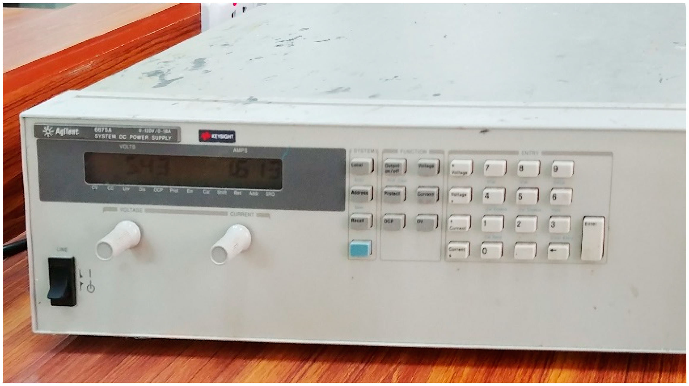
A DC power supply by Keysight Technologies® (Keysight Technologies, Colorado Springs, CO, USA) Colorado Springs, CO, USA (Model: Agilent 6675A) was used to power the electric heater, as shown in Figure 3. Table 2 shows the technical specification of the power supply, and Table 3 shows the power input and their respective heat flux input in the cavity.

2.3. Air Flow Configurations

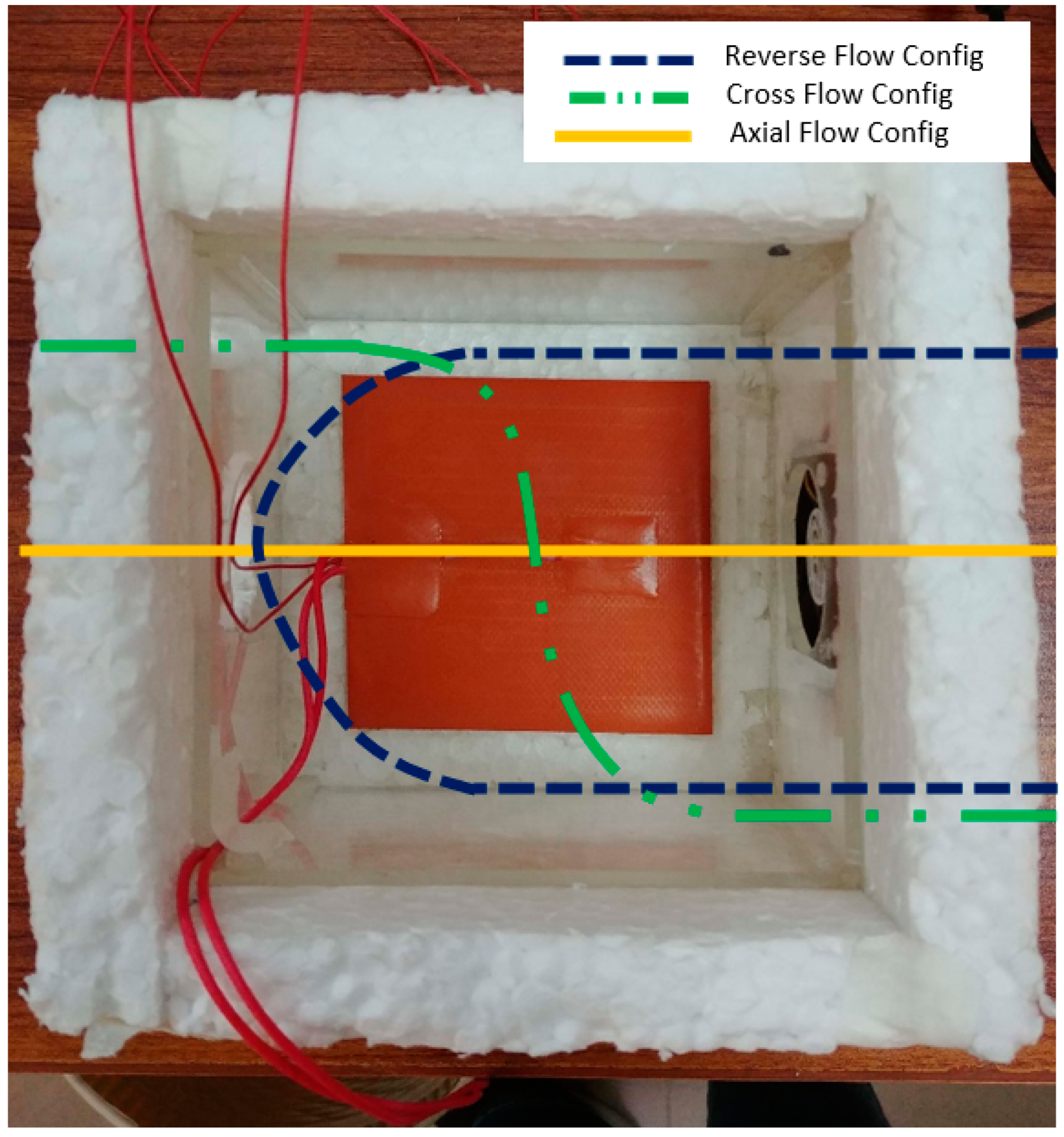
An experimental setup was developed to simulate the real-time conditions of closely packed electronics. The acrylic glass (methyl methacrylate), commonly known as plexiglass, was used to make the cavity as it is economical, lightweight, strong, and has low heat transfer capacity. The cavity was insulated with a thermopore to minimize the heat loss to the surroundings. This heat loss prevention represents the 1 D condition of heat transfer in the cavity. The cavity was designed using the modular design concept. The side walls were replaceable to generate three different airflow configurations, i.e., axial, cross, and reverse flow. The cavity dimensions were 140 × 140 × 80 mm and the silicon pad heater was installed precisely in the center of the cavity. The air velocity was kept constant at 3 m/s during the entire experimentation as this velocity corresponds to the base velocity range used in numerical and simulation studies [5,7,8,9,10]. The airflow configurations are shown in Figure 4.
A Delta Electronic fans (model number AUB0512HHB CA, USA) generates forced airflow within the cavity. The dimensions of the fan are 50 × 50 × 15 mm3. Other technical specifications are given in Table 4.

2.4. Thermocouples Positions

The temperature is measured using OMEGATM thermocouples, which are precisely calibrated on ASTM standards [36]. The temperature in the cavity is measured in three directions (x, y, z), using four K-type thermocouples, having wide temperature range, accuracy, and precision. The maximum discrepancy of the used thermocouples has been found to be ±0.1 °C within a temperature range of 0–100 °C. The technical specifications of thermocouples are mentioned in Table 5.
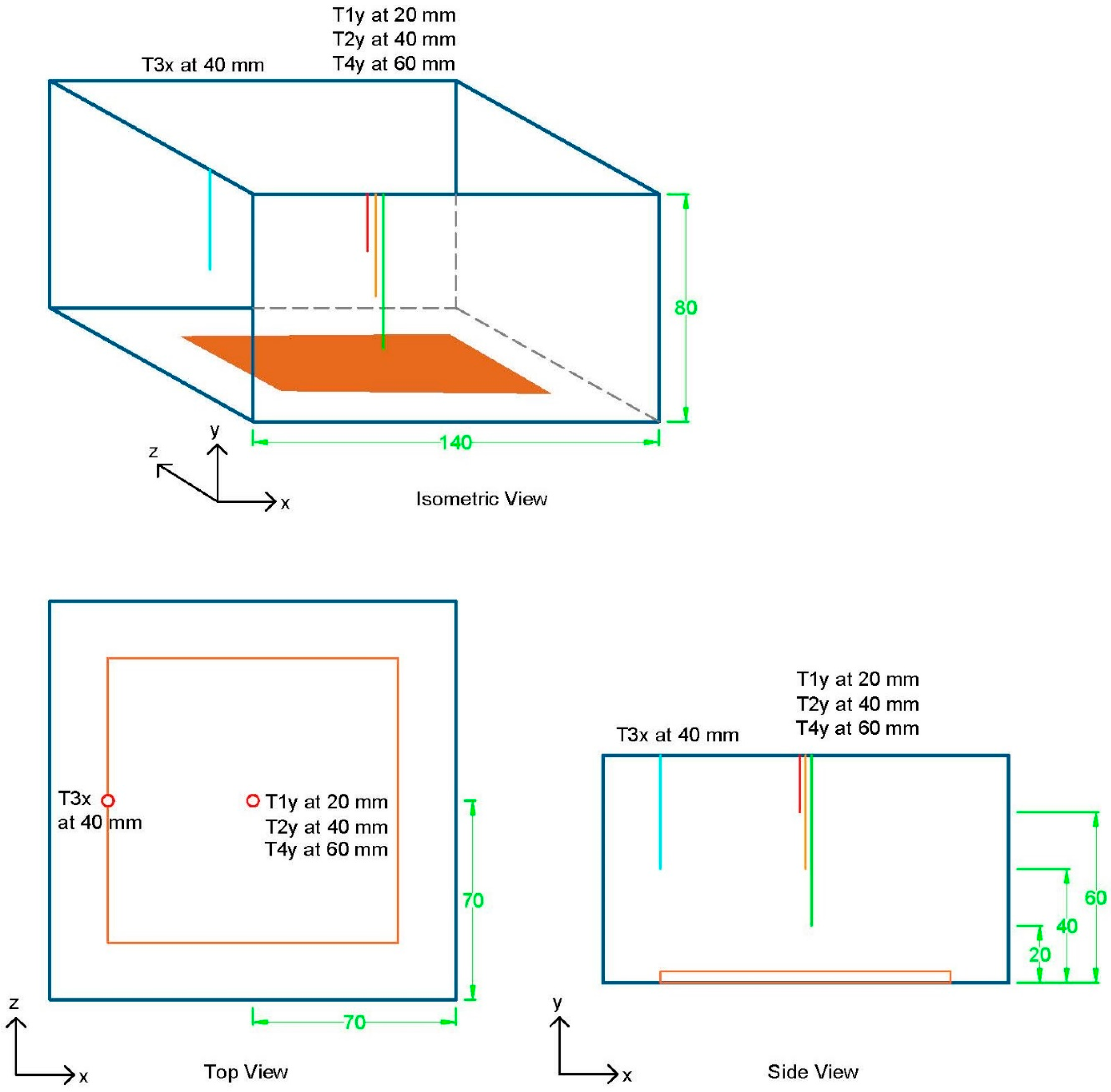
Thermocouples provide analog data, which are then converted to digital form using a national instrumentations (NI-USB-9162) data acquisition system (DAQ). DAQ is further connected to a computer that logs the temperature at an interval of 5 s using LabView. Thermocouples’ placement with their dimension is schematically shown in Figure 5. The designation T1y, T2y, and T4y are at the center of the cavity, i.e., 70 mm along the base of the cavity. These thermocouples are placed at different heights of 20 mm, 40 mm, and 60 mm from the base, and are used to measure the temperature variation in the y direction of the cavity. Similarly, T3x is located 20 mm along the base of the cavity and at a height of 40 mm from the base. T3x measures the x direction temperature variation in the cavity. Araldite is used to properly fix these thermocouples and ensure the cavity’s proper sealing.

3. Results and Discussion

The primary focus of this work is to find the most efficient airflow configuration to reduce the cavity temperature of smart electronics, i.e., increasing the heat dissipation from the cavity, hence lowering the IC’s temperature. So, the data for cavity temperature are obtained and presented graphically. Considering the uniform heating from the electrical heat source and cavity symmetry along the x- and z-axis, the trend obtained in the x-axis can be replicated for the z-axis. The same temperature variation in the x and z directions is recorded using a T3x thermocouple.

3.1. Temperature Profile of Enclosed Cavity

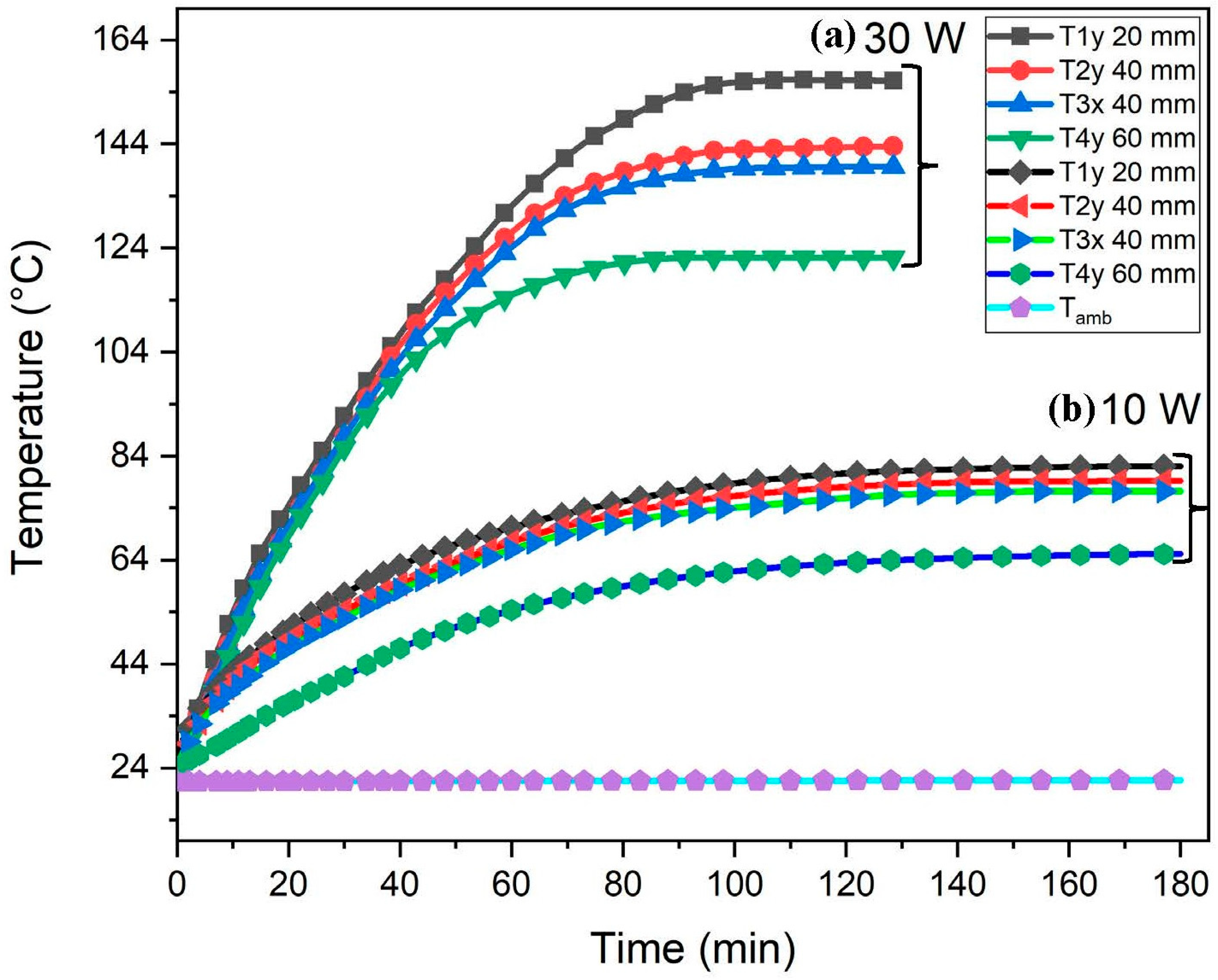
The temperatures measured by various thermocouples within the cavity are plotted against time at 10 W and 30 W power levels. In this configuration, the cavity is thermally isolated from the surroundings using insulation and the thermocouples are fixed in the cavity along respective x, y, and z axis, as shown schematically in Figure 5. This experimentation is carried out to estimate the max temperature achieved in the cavity and to gauge the cooling efficiency of different airflow configurations against it.
The room temperature of the lab is 24 °C, and is maintained constant during experimentation. Initially, when power is supplied to the heater, the temperature at time zero is recorded as 24 °C. As time passes, the heat flux from the silicon pad heater having a surface of 100 × 100 mm2, exchanges heat with air in the cavity through convection, increasing cavity temperature until a steady-state equilibrium is achieved. The max temperature achieved in the cavity is 82 °C and 156 °C at 10 W and 30 W, respectively. For the second case, a steady state is achieved faster due to an increased heat flux input at a higher power level of 30 W for the same cavity. The results are shown in Figure 6 at 10 W and 30 W.

3.2. Temperature Variation in the Cavity with Fan along X, Y, and Z-Axis

Thermocouples are set up in the cavity to record small temperature variations along the X-, Y-, and Z-axis, as shown in Figure 5. Keeping in view the geometrical symmetry, the trends for the x-axis can be replicated for the z-axis. As the temperature varies along the y-axis, thermocouples are positioned vertically with a pitch distance of 20 mm from the base of the cavity. The obtained data describes the temperature variation within the cavity for power ranges of 10 W, 20 W, and 30 W for all three configurations. This temperature variation within the cavity provides the overall view of heat content in the cavity, i.e., more heat is dissipated when the cavity’s temperature distribution is more consistent. Additionally, the regions with higher temperatures are a sign of a poorly ventilated area in a cavity arrangement, which must be considered when constructing an enclosure for commercial use.

3.2.1. For Cross Flow Configuration

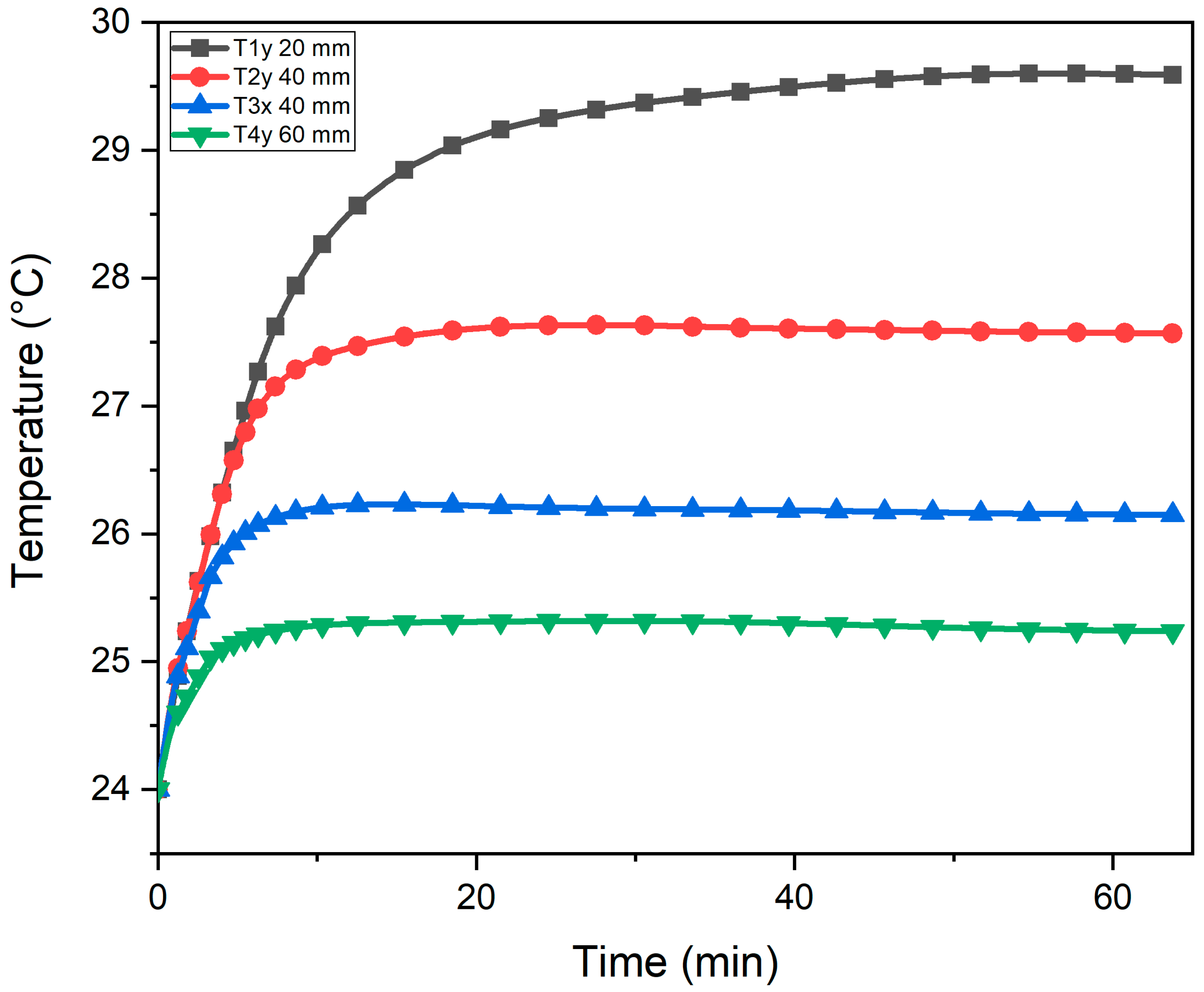
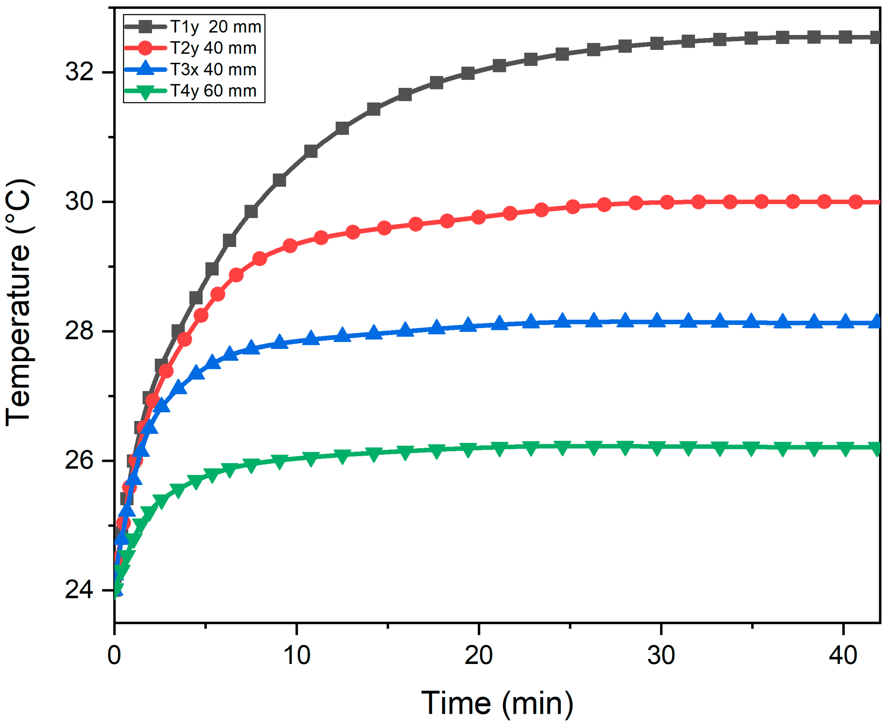
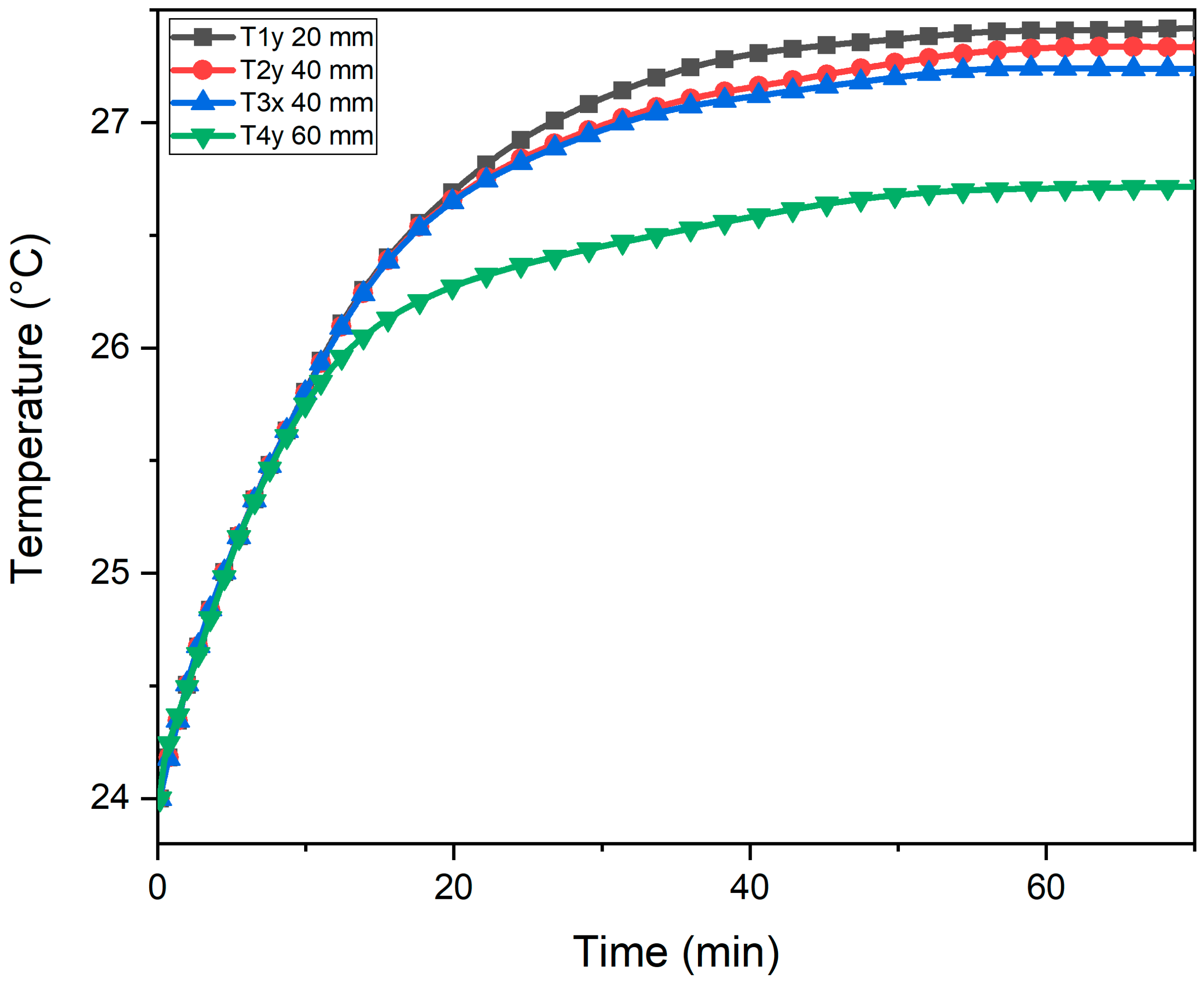
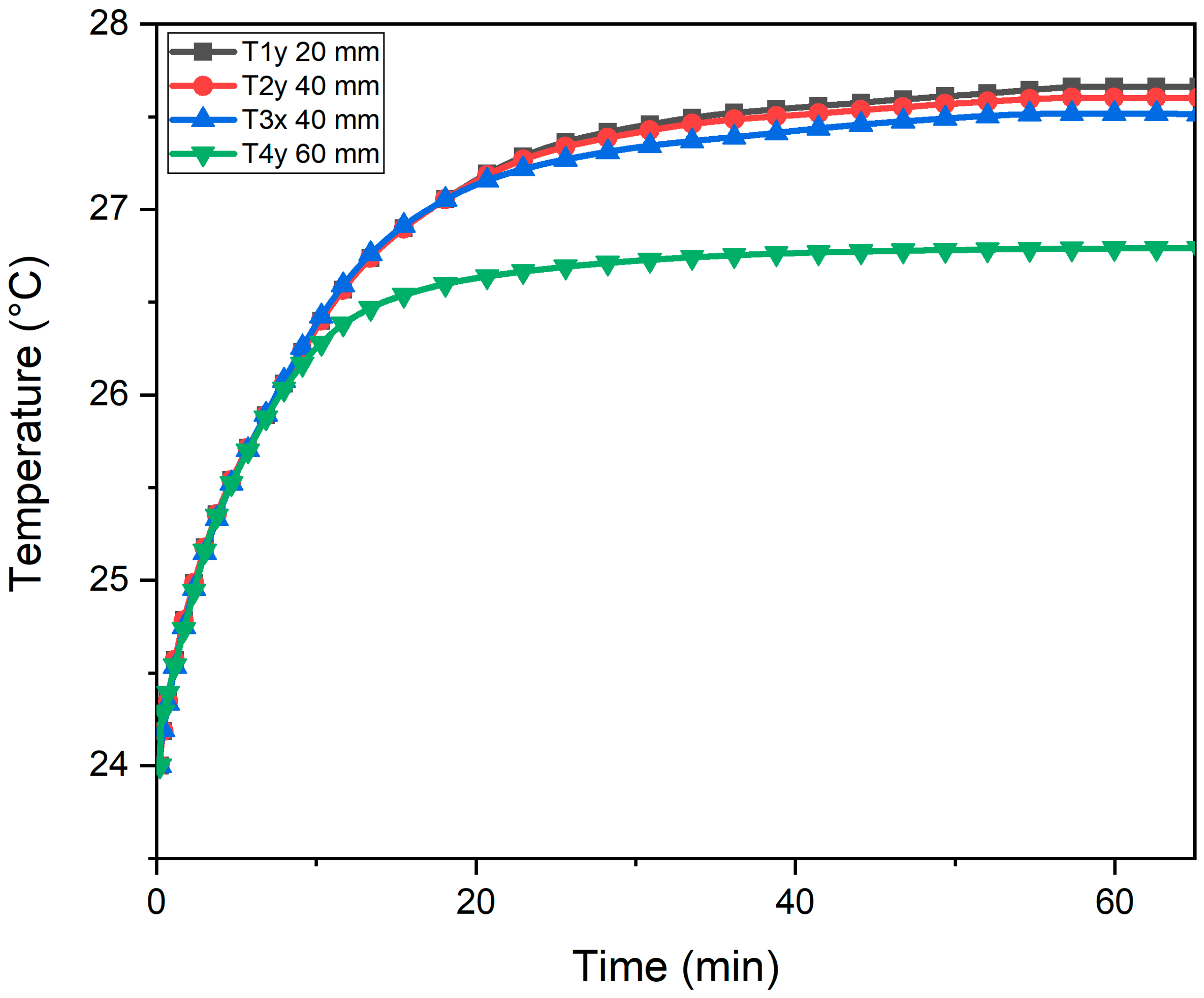
The setup is run at a rated input power of 10 W, 20 W, and 30 W, and after each experiment, we let the setup cool back to the ambient temperature. The heat from the heater is transmitted to the air in the cavity when the input power is provided, causing the cavity temperature to rise over time. Temperature rise trends at 10 W, 20 W, and 30 W are shown in Figure 7, Figure 8 and Figure 9, respectively. There is a steep rise in cavity temperature in the beginning due to a greater temperature difference with the ambient temperature. However, the rate of temperature that increase with the passing of time is substantially reduced when the cavity temperature approaches the equilibrium condition. In the case of crossflow, the forced air entering the cavity also exchanges heat within the cavity; thus, lowering the cavity temperature. The average temperatures obtained within the cavity are 26.1 °C, 27.2 °C, and 29.2 °C for the 10 W, 20 W, and 30 W heat generation rates, respectively. It is observed that at 10 W of heat generation rate, the cavity temperature is more uniform than at 20 W and 30 W. This trend is caused by the fact that as the cavity temperature rises, the sections inside the cavity having no proper ventilation start to accumulate heat, which results in an overall temperature rise in the cavity.

3.2.2. For Reverse Flow Configuration

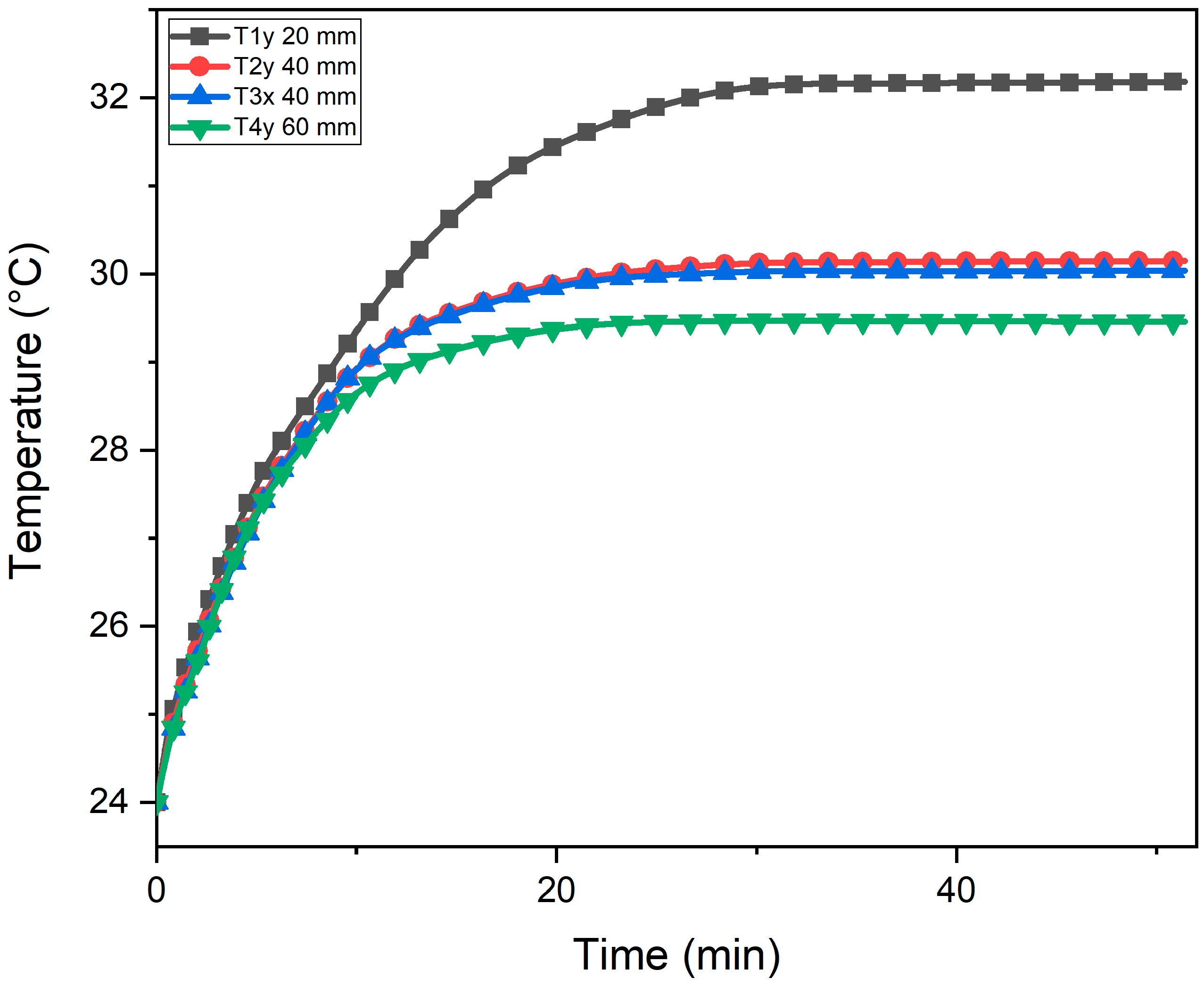
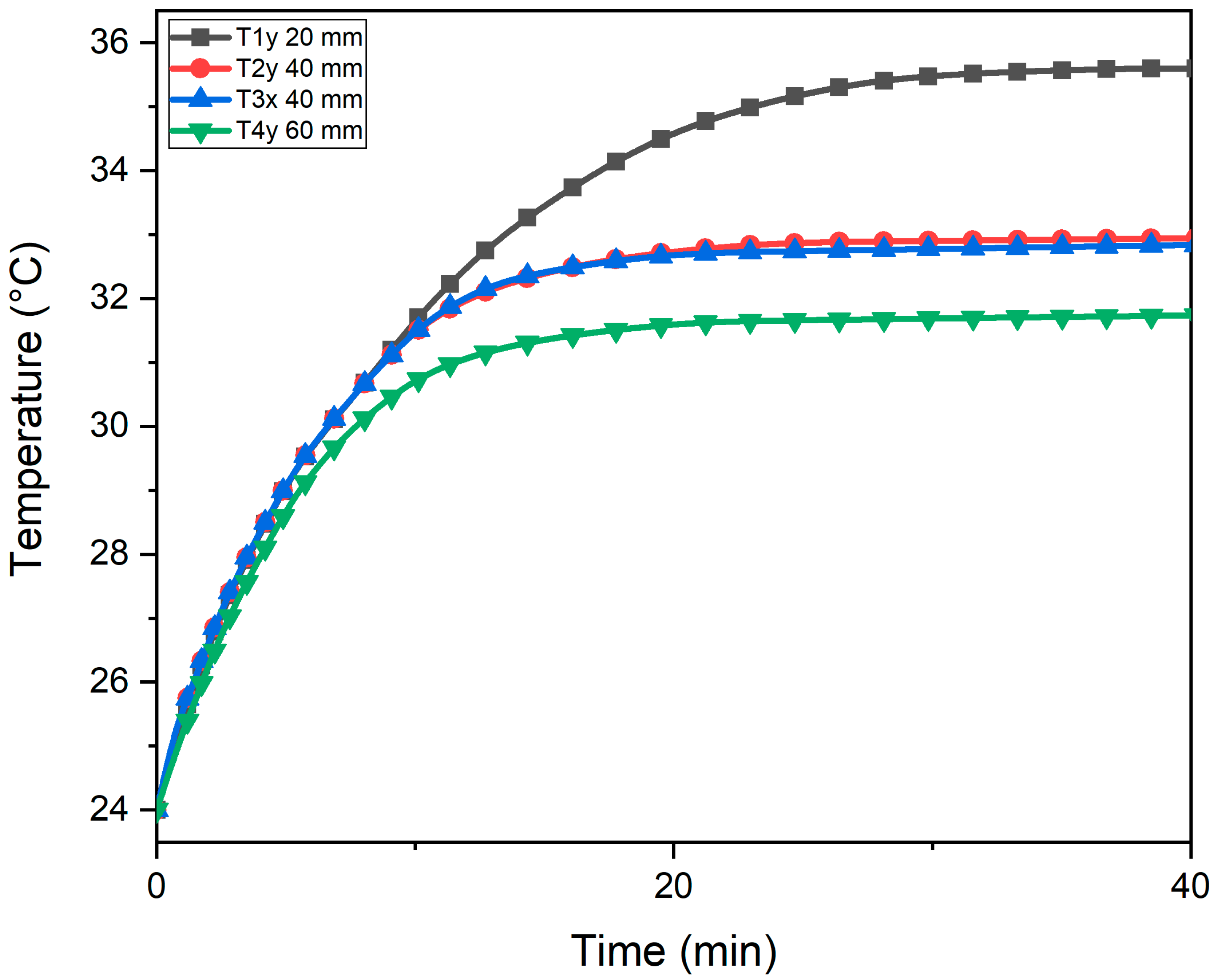
The experiment is repeated for reverse flow at 10 W, 20 W, and 30 W power levels. The average temperatures obtained within the cavity are 28.1 °C, 30.4 °C and 33.4 °C at 10 W, 20 W, and 30 W of heat generation rate, respectively. The peak temperature (Tmax) values plotted against time are shown in Figure 10, Figure 11 and Figure 12. Tmax values are higher in the case of reverse flow configuration due to the low heat transfer rate in the cavity, i.e., the indicator of low heat dissipation. The lower heat dissipation in reverse flow configuration is due to the more erratic airflow in the cavity owing to no specific air path, which causes cavity air to form swirl/circulate within the cavity. On the other hand, forced air entering the cavity does not properly mix with cavity air and leaves the cavity without sufficient heat transfer, forming poorly ventilated areas in the cavity.

3.2.3. For Axial Flow Configuration

The experiments were repeated for the axial flow configuration at 10 W, 20 W, and 30 W. Temperature is recorded and plotted against time as shown in Figure 13, Figure 14 and Figure 15. The average temperature obtained within the cavity is 25.4 °C, 27.2 °C and 27.4 °C at 10 W, 20 W, and 30 W, respectively. However, it can be observed from the graph that the max temperature (Tmax) reached in the cavity is significantly lower than the case of the cross and reverse flow conditions. The reason being the properly ventilated cavity design and low hindrance to the air entering the cavity. This accounts for a large quantity of ambient air entering the cavity, i.e., the temperature delta between ambient entering air and cavity temperature is higher, resulting in more heat dissipation from the cavity.

3.3. Cavity Configuration Comparison

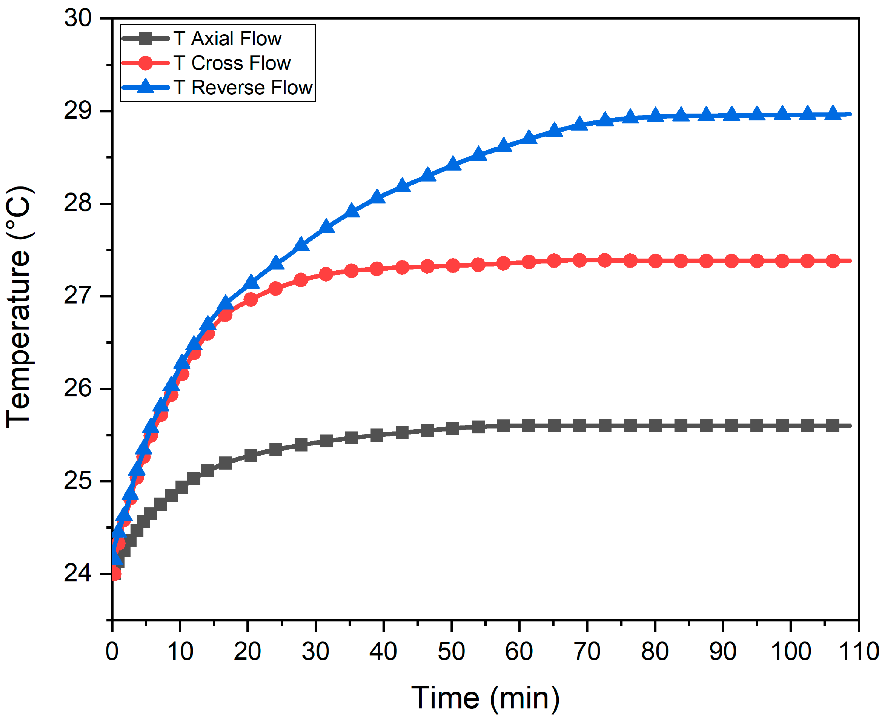
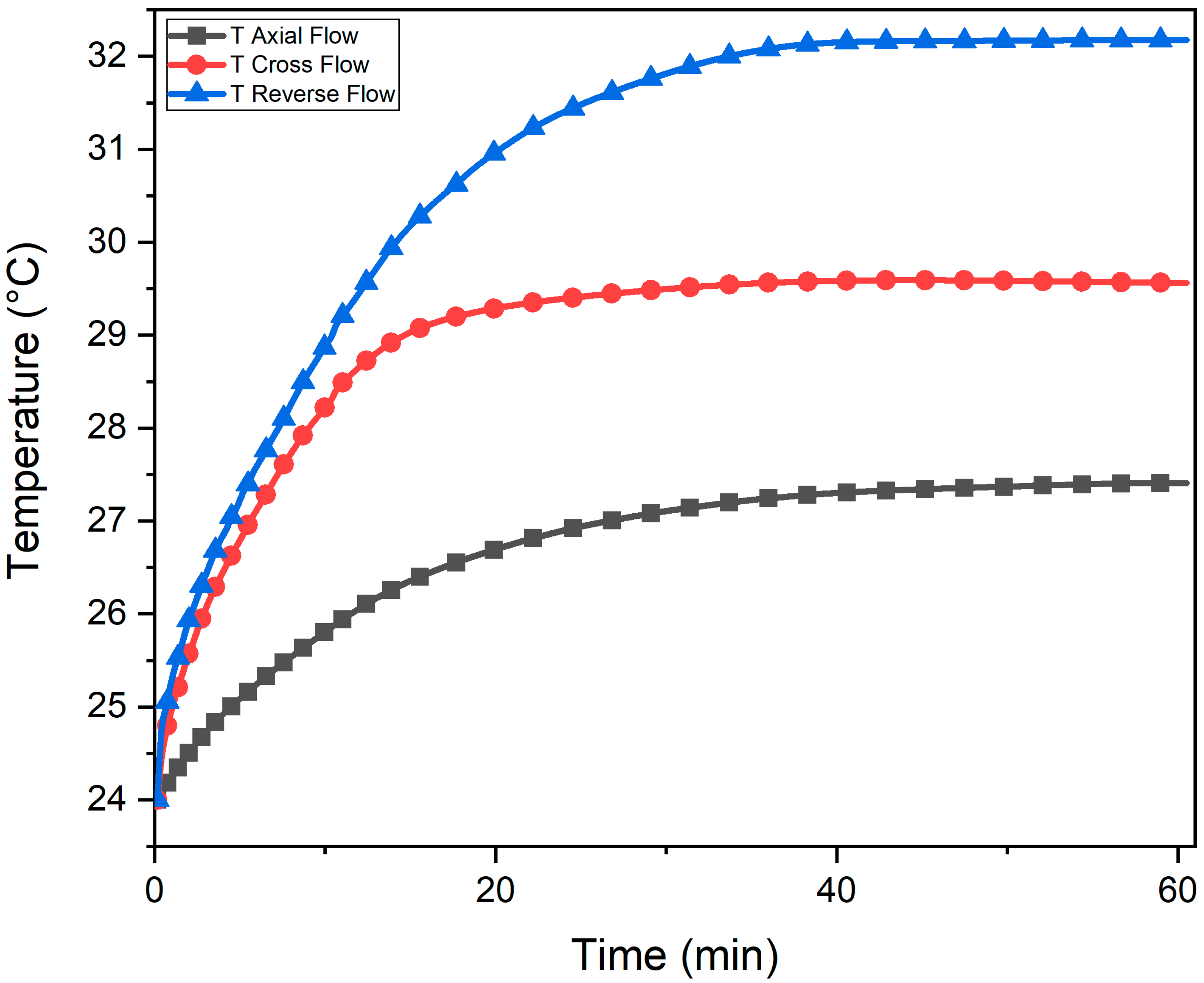
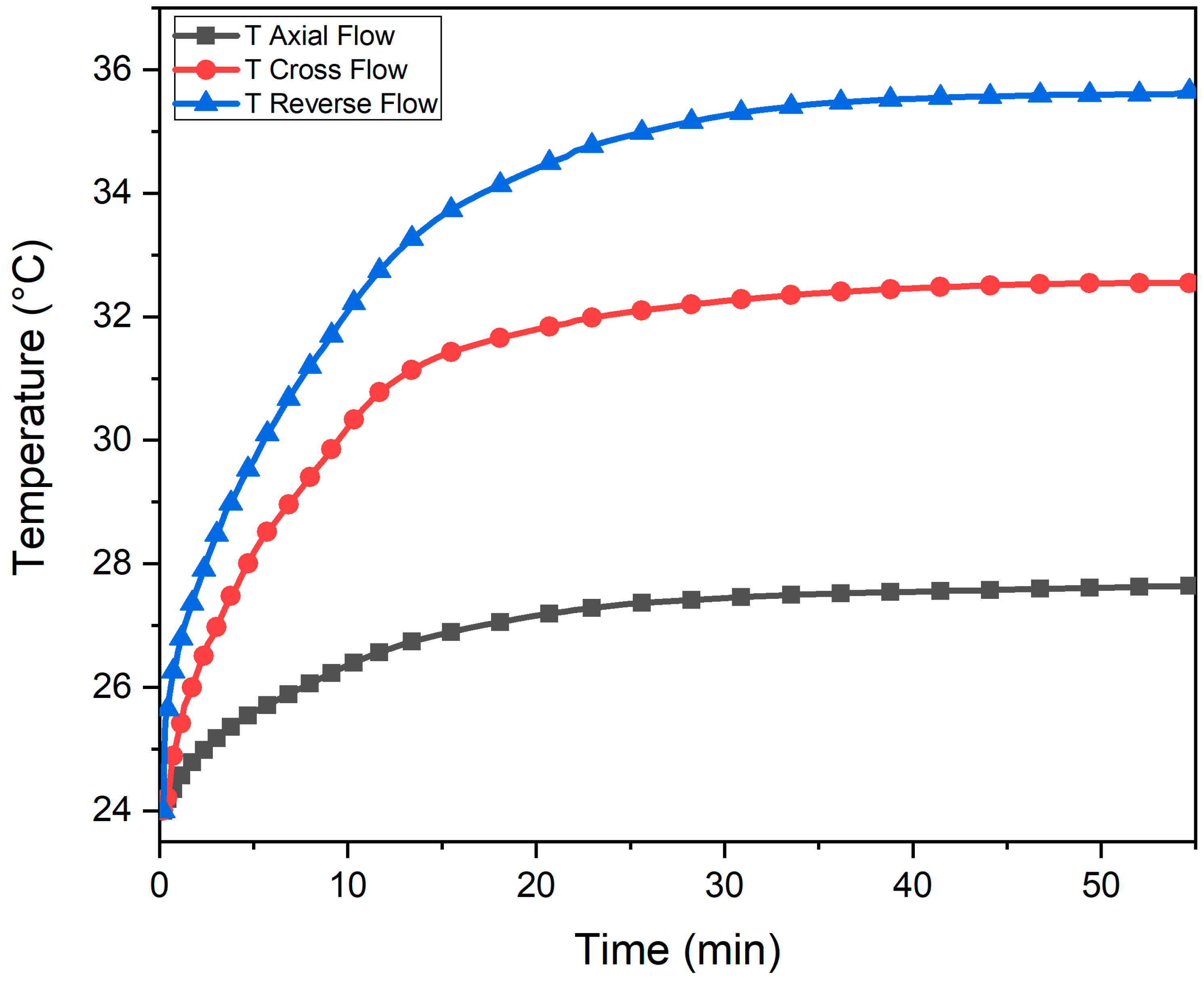
This section compares different cavity configurations to find the most suitable configuration for max heat dissipation from the cavity. The experiments are performed at three power levels to observe the trends with an increase in power level. The results are shown in Figure 16, Figure 17 and Figure 18. It can be observed from the graphs that the maximum temperature drop is obtained in case of axial flow configuration. In comparison, the crossflow cavity performs better than the reverse flow configuration. The airflow characteristics within the cavity can explain these trends. As in the case of axial flow configuration, the flow is streamlined, facing minimum obstruction at the cavity entrance. Hence, the maximum air flow rate passes the cavity compared to the cross or reverse flow configuration. Additionally, the air enters the cavity at ambient temperature, so a large temperature difference allows maximum heat transfer. The same parameters contribute to the crossflow configuration’s better heat transfer capabilities when compared with reverse-flow configuration. Next, experiments are conducted at 10 W, 20 W, and 30 W power levels, and the trends depict similar results as the 10 W power level.

3.4. The Effect of Varying Power Levels

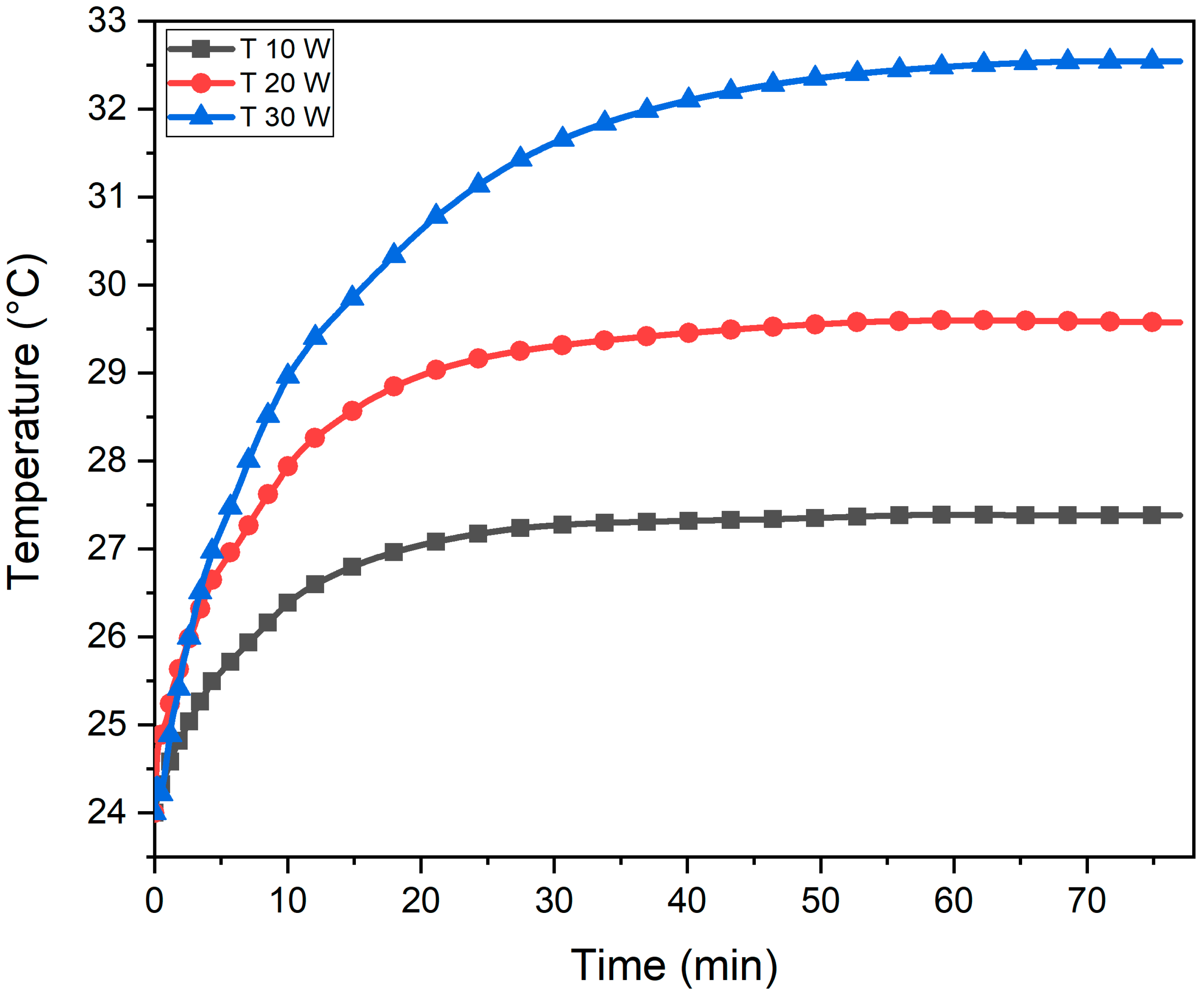
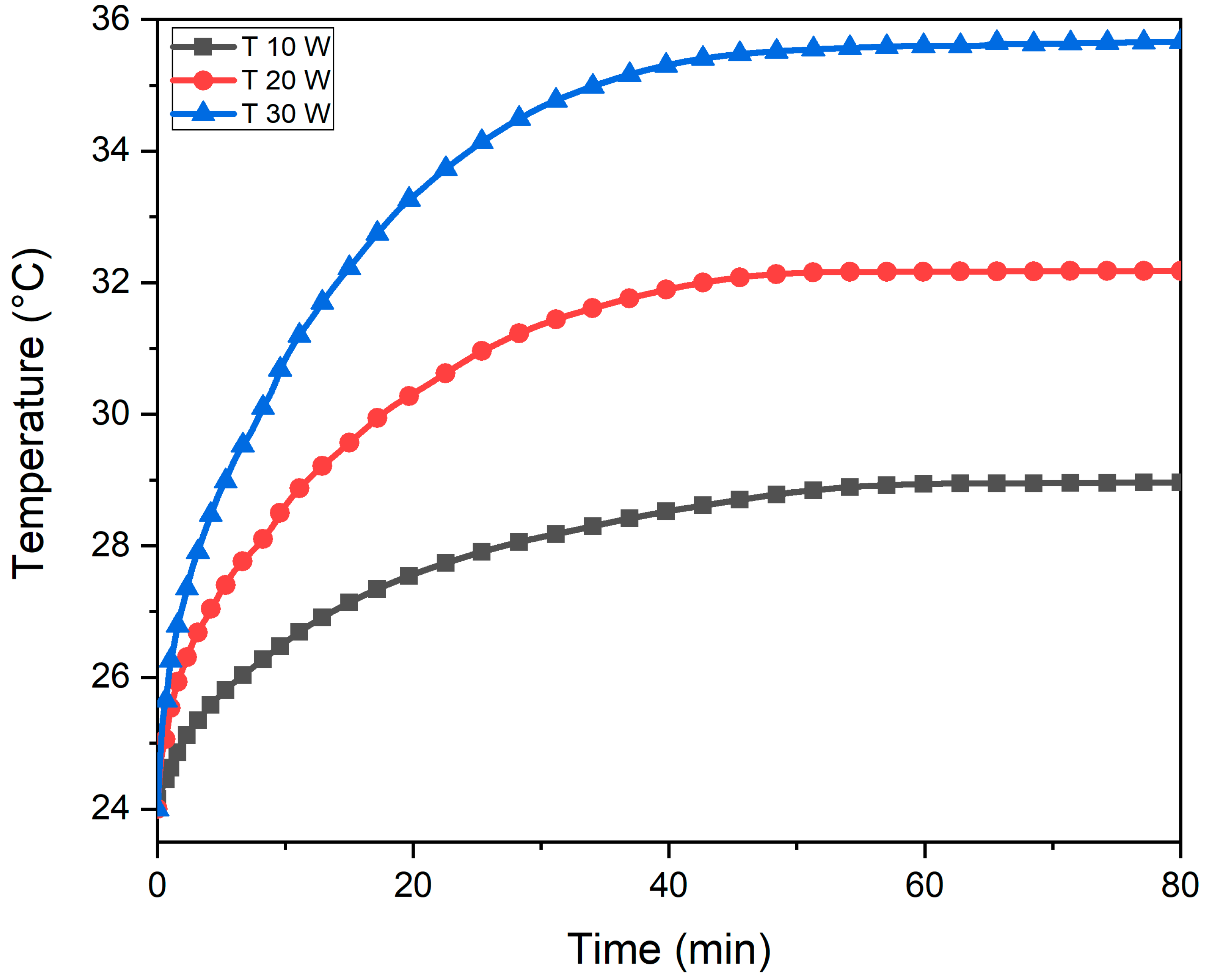
Experiments are performed on each cavity configuration to analyze the effect of increasing power levels on cavity cooling by increasing power levels from 10 W to 30 W. Graphical trends are shown in Figure 19, Figure 20 and Figure 21. Tmax is measured after a steady state is achieved in the cavity. Tmax is directly proportional to power level, i.e., for each cavity configuration, the Tmax increases with an increase in power level. Within the cavity, two processes are taking place simultaneously; heat flux generation in the heater and heat dissipation from the cavity by forced airflow. The maximum temperature achieved within the cavity is determined at the equilibrium state of these two processes.

4. Conclusions

Experimentation is conducted to find the most efficient and optimized forced air cooling technique for closely packed smart electronics. Optimization scenarios include the effect of temperature variation within the cavity, air flow configuration comparison, and the effect of varying power levels. Based on experiments conducted in this research, the following conclusions are made:
i.
The maximum temperature within the cavity without external cooling source reached up to 82 °C and 156 °C at 10 W and 30 W of heater input power, respectively;
ii.
The axial flow configuration is the most efficient airflow configuration, i.e., maximum temperature drop was achieved. About 9.6%, 10.75%, and 17.91% temperature drop was observed at 10 W, 20 W, and 30 W, respectively, compared to reverse flow configuration. However, a large Tmax drop of 69~82.5% is obtained compared to an enclosed cavity with no thermal management;
iii.
For crossflow configurations, the temperature recorded in the cavity is 7.29%, 10.68%, and 12.76% lower than the reverse flow at 10 W, 20 W, and 30 W, respectively. However, compared to enclosed cavities without thermal management, a temperature drop of 65.7~78.6% is obtained;
iv.
For a lower heat generation rate, the cavity temperature is more uniform. Therefore, a more sophisticated thermal management method is required for temperature control at elevated temperatures;
v.
The effect of varying power levels suggests the direct relation between input power level and max temperature Tmax obtained within the cavity.

5. Future Work

In the current study, the effect of a forced air convection cooling system has been studied experimentally by changing the airflow configurations. Future work will focus on the replication of the same study at different airflow velocities, the optimization of the current thermal management technique using various fin types (pin, square, rectangular) fins with phase change materials, heat pipes, and hybrid configurations of fins with a heat pipe to draw a direct comparison for the most efficient cooling strategy.

Author Contributions

Formal analysis, investigation, validation, writing—review & editing, S.S.; conceptualization, resources, supervision, A.H.; writing—review & editing, I.A.; data curation, formal analysis, investigation, writing—original draft, H.S.; conceptualization, resources, H.M.A. All authors have read and agreed to the published version of the manuscript.

Funding

This research was conducted under Department of Mechanical Engineering, University of Engineering and Technology Taxila and no external funding was received.

Data Availability Statement

Not applicable.

Conflicts of Interest

The authors declare no conflict of interest.

Nomenclature

AOperating Current (A)
CBattery’s C Rating
DaDarcy Number
dbNoise (db)
Mass Flow Rate (kg/s)
QVolumetric Flow Rate (m3/min)
qHeat Flux (kW/m2)
ReReynolds Number
rpmRevolution per minute (rpm)
TambAmbient Temperature (°C)
TThermocouple Temperature (°C)
VOperating Voltage (V)
vVelocity (ms−1)
WOperating Power (W)
Resistance (Ω)
Acronyms
CFDComputational Fluid Dynamics
DAQData Acquisition System
ICIntegrated Circuit
LIBLithium-ion Batteries
Li-ionLithium-ion
NCNatural Convection
NINational Instrumentations
OEM Original Equipment Manufacturers
PCMPhase Change Material
PDPorous Deflectors
PVPhotovoltaic

References

  1. Xiong, R.; Sun, F.; Gong, X.; Gao, C. A data-driven based adaptive state of charge estimator of lithium-ion polymer battery used in electric vehicles. Appl. Energy 2014, 113, 1421–1433. [Google Scholar] [CrossRef]
  2. Xiong, R.; Sun, F.; Chen, Z.; He, H. A data-driven multi-scale extended Kalman filtering based parameter and state estimation approach of lithium-ion olymer battery in electric vehicles. Appl. Energy 2014, 113, 463–476. [Google Scholar] [CrossRef]
  3. Na, X.; Kang, H.; Wang, T.; Wang, Y. Reverse layered air flow for Li-ion battery thermal management. Appl. Therm. Eng. 2018, 143, 257–262. [Google Scholar] [CrossRef]
  4. Panchal, S.; Mathewson, S.; Fraser, R.; Culham, R.; Fowler, M. Measurement of Temperature Gradient (dT/dy) and Temperature Response (dT/dt) of a Prismatic Lithium-Ion Pouch Cell with LiFePO4 Cathode Material; SAE Technical Papers; SAE International: Warrendale, PA, USA, 2017. [Google Scholar] [CrossRef]
  5. Chen, K.; Chen, Y.; Li, Z.; Yuan, F.; Wang, S. Design of the cell spacings of battery pack in parallel air-cooled battery thermal management system. Int. J. Heat. Mass. Transf. 2018, 127, 393–401. [Google Scholar] [CrossRef]
  6. Chen, K.; Song, M.; Wei, W.; Wang, S. Structure optimization of parallel air-cooled battery thermal management system with U-type flow for cooling efficiency improvement. Energy 2018, 145, 603–613. [Google Scholar] [CrossRef]
  7. Chen, K.; Song, M.; Wei, W.; Wang, S. Design of the structure of battery pack in parallel air-cooled battery thermal management system for cooling efficiency improvement. Int. J. Heat. Mass. Transf. 2019, 132, 309–321. [Google Scholar] [CrossRef]
  8. Chen, K.; Wang, S.; Song, M.; Chen, L. Structure optimization of parallel air-cooled battery thermal management system. Int. J. Heat. Mass. Transf. 2017, 111, 943–952. [Google Scholar] [CrossRef]
  9. Chen, K.; Wu, W.; Yuan, F.; Chen, L.; Wang, S. Cooling efficiency improvement of air-cooled battery thermal management system through designing the flow pattern. Energy 2019, 167, 781–790. [Google Scholar] [CrossRef]
  10. Shahid, S.; Agelin-Chaab, M. Development and analysis of a technique to improve air-cooling and temperature uniformity in a battery pack for cylindrical batteries. Therm. Sci. Eng. Prog. 2018, 5, 351–363. [Google Scholar] [CrossRef]
  11. Tong, W.; Somasundaram, K.; Birgersson, E.; Mujumdar, A.S.; Yap, C. Thermo-electrochemical model for forced convection air cooling of a lithium-ion battery module. Appl. Therm. Eng. 2016, 99, 672–682. [Google Scholar] [CrossRef]
  12. Yang, Y.; Huang, X.; Cao, Z.; Chen, G. Thermally conductive separator with hierarchical nano/microstructures for improving thermal management of batteries. Nano Energy 2016, 22, 301–309. [Google Scholar] [CrossRef] [Green Version]
  13. Zhou, H.; Zhou, F.; Xu, L.; Kong, J.; Yang, Q. Thermal performance of cylindrical Lithium-ion battery thermal management system based on air distribution pipe. Int. J. Heat. Mass. Transf. 2019, 131, 984–998. [Google Scholar] [CrossRef]
  14. Park, H. A design of air flow configuration for cooling lithium ion battery in hybrid electric vehicles. J. Power Sources 2013, 239, 30–36. [Google Scholar] [CrossRef]
  15. Al-Zareer, M.; Dincer, I.; Rosen, M.A. A novel approach for performance improvement of liquid to vapor based battery cooling systems. Energy Convers Manag. 2019, 187, 191–204. [Google Scholar] [CrossRef]
  16. Zheng, Y.; Shi, Y.; Huang, Y. Optimisation with adiabatic interlayers for liquid-dominated cooling system on fast charging battery packs. Appl. Therm. Eng. 2019, 147, 636–646. [Google Scholar] [CrossRef]
  17. Zhao, J.; Rao, Z.; Li, Y. Thermal performance of mini-channel liquid cooled cylinder based battery thermal management for cylindrical lithium-ion power battery. Energy Convers. Manag. 2015, 103, 157–165. [Google Scholar] [CrossRef]
  18. Zhao, C.; Sousa, A.C.M.; Jiang, F. Minimization of thermal non-uniformity in lithium-ion battery pack cooled by channeled liquid flow. Int. J. Heat. Mass. Transf. 2019, 129, 660–670. [Google Scholar] [CrossRef]
  19. Panchal, S.; Gudlanarva, M.K.; Tran, M.; Fraser, R.; Fowler, M. High reynold’s number turbulent model for micro-channel cold plate using reverse engineering approach for water-cooled battery in electric vehicles. Energies 2020, 13, 1638. [Google Scholar] [CrossRef] [Green Version]
  20. Panchal, S.; Dincer, I.; Agelin-Chaab, M.; Fraser, R.; Fowler, M. Transient electrochemical heat transfer modeling and experimental validation of a large sized LiFePO4/graphite battery. Int. J. Heat. Mass. Transf. 2017, 109, 1239–1251. [Google Scholar] [CrossRef]
  21. Wiriyasart, S.; Hommalee, C.; Sirikasemsuk, S.; Prurapark, R.; Naphon, P. Thermal management system with nanofluids for electric vehicle battery cooling modules. Case Stud. Therm. Eng. 2020, 18, 100583. [Google Scholar] [CrossRef]
  22. Akbarzadeh, M.; Jaguemont, J.; Kalogiannis, T.; Karimi, D.; He, J.; Jin, L.; Xie, P.; Van Mierlo, J.; Berecibar, M. A novel liquid cooling plate concept for thermal management of lithium-ion batteries in electric vehicles. Energy Convers. Manag. 2021, 231, 113862. [Google Scholar] [CrossRef]
  23. Li, X.; He, F.; Ma, L. Thermal management of cylindrical batteries investigated using wind tunnel testing and computational fluid dynamics simulation. J. Power Sources 2013, 238, 395–402. [Google Scholar] [CrossRef]
  24. Liu, J.; Li, H.; Li, W.; Shi, J.; Wang, H.; Chen, J. Thermal characteristics of power battery pack with liquid-based thermal management. Appl. Therm. Eng. 2020, 164, 114421. [Google Scholar] [CrossRef]
  25. Lee, J.; Abidi, A.; Mohammad Sajadi, S.; El-Shafay, A.S.; Degani, M.; Sharifpur, M. Study of the effect of the aspect ratio of a cylindrical lithium-ion battery enclosure in an air-cooled thermal management system. J. Energy Storage 2022, 45, 103684. [Google Scholar] [CrossRef]
  26. Selimefendigil, F.; Şirin, C.; Öztop, H.F. Effect of different heat transfer fluids on discharging performance of phase change material included cylindrical container during forced convection. J. Cent. South Univ. 2021, 28, 3521–3533. [Google Scholar] [CrossRef]
  27. Omri, M.; Selimefendigil, F.; Smaoui, H.T.; Kolsi, L. Cooling system design for photovoltaic thermal management by using multiple porous deflectors and nanofluid. Case Stud. Therm. Eng. 2022, 39, 102405. [Google Scholar] [CrossRef]
  28. Maatoug, S.; Moulahi, A.; Bazuhair, N.; Alqarni, S.; Selimefendigil, F.; Aich, W.; Kolsi, L.; Mhimid, A. Pulsating multiple nano-jet impingement cooling system design by using different nanofluids for photovoltaic (PV) thermal management. Case Stud. Therm. Eng. 2023, 41, 102650. [Google Scholar] [CrossRef]
  29. Chen, F.; Huang, R.; Wang, C.; Yu, X.; Liu, H.; Wu, Q.; Qian, K.; Bhagat, R. Air and PCM cooling for battery thermal management considering battery cycle life. Appl. Therm. Eng. 2020, 173, 115154. [Google Scholar] [CrossRef]
  30. Behi, H.; Karimi, D.; Behi, M.; Ghanbarpour, M.; Jaguemont, J.; Sokkeh, M.A.; Gandoman, F.H.; Berecibar, M.; Van Mierlo, J. A new concept of thermal management system in Li-ion battery using air cooling and heat pipe for electric vehicles. Appl. Therm. Eng. 2020, 174, 115280. [Google Scholar] [CrossRef]
  31. Khalid, S.U.; Ali, H.M.; Nasir, M.A.; Pasha, R.A.; Said, Z.; Sundar, L.S.; Hussein, A.K. Experimental investigation of thermal performance characteristics of sintered copper wicked and grooved heat pipes: A comparative study. J. Cent. South Univ. 2021, 28, 3507–3520. [Google Scholar] [CrossRef]
  32. Gocmen, S.; Cetkin, E. Emergence of elevated battery positioning in air cooled battery packs for temperature uniformity in ultra-fast dis/charging applications. J. Energy Storage 2022, 45, 103516. [Google Scholar] [CrossRef]
  33. Wang, H.; Tao, T.; Xu, J.; Mei, X.; Liu, X.; Gou, P. Cooling capacity of a novel modular liquid-cooled battery thermal management system for cylindrical lithium ion batteries. Appl. Therm. Eng. 2020, 178, 115591. [Google Scholar] [CrossRef]
  34. Mustafa, J. Effect of inlet and outlet size, battery distance, and air inlet and outlet position on the cooling of a lithium-ion battery pack and utilizing outlet air of cooling system to heat an air handling unit. J. Energy Storage 2022, 46, 103826. [Google Scholar] [CrossRef]
  35. Wang, H.; Ma, L. Thermal management of a large prismatic battery pack based on reciprocating flow and active control. Int. J. Heat. Mass. Transf. 2017, 115, 296–303. [Google Scholar] [CrossRef]
  36. Burns, G.W.; Guthrie, W.F.; Scroger, M.G.; Strouse, G.F.; Croarkin, M.C. Letter-Designated Thermocouple Types Based on the ITS-90; United States Department of Commerce Technology Administration; National Institute of Standards and Technology: Gaithersburg, MD, USA, 1993. [Google Scholar]
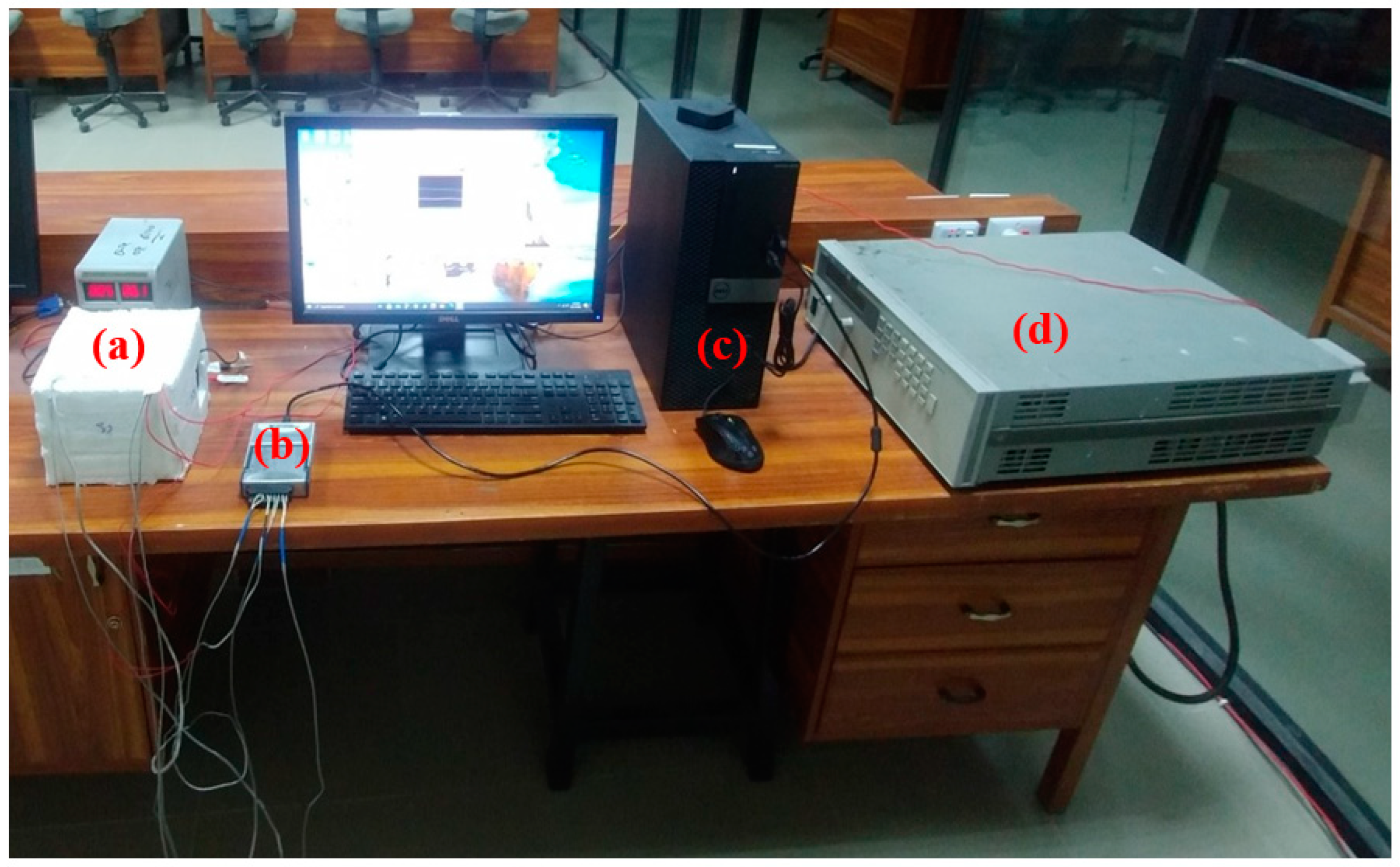
Figure 1. Experimental setup in laboratory: (a) Cavity; (b) Data acquisition system; (c) Data logging PC; (d) Power supply.
Fire 06 00087 g001
Figure 2. Schematic representation of the setup.
Fire 06 00087 g002
Figure 3. Power supply (Agilent 6675A).
Fire 06 00087 g003
Figure 4. Axial flow, cross flow, and reverse flow configuration.
Fire 06 00087 g004
Figure 5. Schematic diagram for thermocouples positioning in a cavity.
Fire 06 00087 g005
Figure 6. Temperature profile for enclosed cavity: (a) At input power of 10 W; (b) At input power of 30 W.
Fire 06 00087 g006
Figure 7. Temperature profile along the x- and y-axis for crossflow configuration with 10 W power input.
Fire 06 00087 g007
Figure 8. Temperature profile along the x- and y-axis for crossflow configuration with 20 W power input.
Fire 06 00087 g008
Figure 9. Temperature profile along the x- and y-axis for crossflow configuration with 30 W power input.
Fire 06 00087 g009
Figure 10. Temperature profile along the x- and y-axis for reverse flow configuration with power input of 10 W.
Fire 06 00087 g010
Figure 11. Temperature profile along the x- and y-axis for reverse flow configuration with power input of 20 W.
Fire 06 00087 g011
Figure 12. Temperature profile along the x- and y-axis for reverse flow configuration with power input of 30 W.
Fire 06 00087 g012
Figure 13. Temperature profile along the x- and y-axis for axial flow configuration with power input of 10 W.
Fire 06 00087 g013
Figure 14. Temperature profile along the x- and y-axis for axial flow configuration with power input of 20 W.
Fire 06 00087 g014
Figure 15. Temperature profile along the x- and y-axis for axial flow configuration with power input of 30 W.
Fire 06 00087 g015
Figure 16. Cavity configuration comparison at a power level of 10 W.
Fire 06 00087 g016
Figure 17. Cavity configuration comparison at a power level of 20 W.
Fire 06 00087 g017
Figure 18. Cavity configuration comparison at a power level of 30 W.
Fire 06 00087 g018
Figure 19. Effect of varying power level on crossflow configuration.
Fire 06 00087 g019
Figure 20. Effect of varying power level on reverse flow configuration.
Fire 06 00087 g020
Figure 21. Effect of varying power level on axial flow configuration.
Fire 06 00087 g021
Table 1. Technical details of silicone pad heater.
ItemPower (W)Voltage (V)Current (A)Resistance (Ω)Temperature Range (°C)Tolerance
Specifications50124.12.88155–160−/+10%
Table 2. Technical specification of power supply.
ParameterVoltage Range
(V)
Current Range
(A)
Programming Accuracy
VoltageCurrent
Agilent 6675A0~1200~180.04% + 120 mV0.1% + 12 mA
Table 3. Power values and their heat fluxes.
Power (W)10 W20 W30 W
q (kW/m2)123
Table 4. Technical details of the fan.
ItemPower
(W)
Voltage (V)Current (A)Speed (R.P.M.)Max Air Flow (m3/min)Noise (db)
Specifications2.16120.1874000.57238.5
Table 5. Technical details of thermocouples.
ItemMakeTypeTemperature Range
(°C)
% Accuracy
SpecificationOMEGATMK-Type−200~12500.75
Disclaimer/Publisher’s Note: The statements, opinions and data contained in all publications are solely those of the individual author(s) and contributor(s) and not of MDPI and/or the editor(s). MDPI and/or the editor(s) disclaim responsibility for any injury to people or property resulting from any ideas, methods, instructions or products referred to in the content.