1. Introduction
Tall buildings and skyscrapers are becoming more common in modern cities. As buildings become taller, the evacuation of occupants during emergency situations would become more challenging, especially during fire-related emergencies where smoke can very quickly reduce visibility along egress paths. The current provisions mandated in the National Construction Code (NCC) and the Building Code of Australia (BCA) for smoke control and detection remains unchanged for all buildings over 25 m in height, with no additional consideration for skyscrapers and supertall buildings.
Smoke control systems particularly stair pressurization systems are fundamental features of a high-rise building to ensure the safe egress of the occupants. The presence of smoke in stairway chutes could prevent the effective and safe egress of building occupants, potentially trapping them during fire events. Even small amounts of smoke could prevent occupants on higher floors from entering a staircase to exit the building. The use of pressurization as a means of controlling smoke, which can be dated back over six decades [
1], has gained widespread use among international building codes in the most recent 20 years. Stair pressurization systems use doors and airflow to generate pressure differentials providing a sort of barrier which stops smoke flow into fire isolated staircases where occupants are egressing [
2]. In fire investigations, a commonly used term is called fire origin. The term fire origin means the place where a fire starts. This may be an exact point or a general area. The function of stair pressurization systems is simply to keep smoke out of the fire stair that occupants must egress via and does nothing to stop the corridor on the level of fire origin from filling with smoke. This implies that a considerable amount of smoke could potentially be present in the corridor by the time the fire brigade arrives, which can make fighting the fire difficult due to the low visibility provided [
3].
Early stair pressurization systems functioned via a single inlet located at the top of a building, directly supplying air into the space it was required at a given flow rate [
4]. Initial tests quickly noted that the pressure differentials near doors could cause them to be exceedingly difficult to open, resulting in many designers turning to the use of systems utilizing multiple supply points in order to improve redundancy and provide better results [
4]. There are several problems that can have a significant impact on the performance of a stair pressurization system, including but not limited to: leakage within the fire stair simply due to construction, wind, and the stack effect caused by pressure and temperature differences in the inside and outside of the building which is particularly evident during winter [
5].
As buildings become taller the possibility for multiple doors to be opened at a time significantly increases. Any additional open doors could cause the performance of the stair pressurization system to drop considerably, allowing smoke to breach the barrier usually created by the pressure differential. In this situation, the system is ineffectual in life safety [
6]. It is further noted that there is no need to take the stack effect into account in design in many international standards, meaning that in certain weather conditions the force required to open doors to the stairs could exceed the 110 N maximum. In this scenario, the doors may be too difficult to open for some occupants, essentially trapping them.
In 2009 Miller [
6] published a study focused on how pressure differentials across doorways in fire stairs change with building height, with buildings up to 30 storeys high tested. He concluded that stair pressurization systems are adequate for protection in buildings up to and including 30 m in height, provided that minimal doors are open at any one time. It is however noted that this study disregarded the amount of force required to open doors at the increased heights [
6]. Ferreira [
7] published a paper finding that storeys above 25 m would exceed the maximum force allowances required to open doors. It was also found that the higher the building is, the more door opening impacts the performance of the system, with up to 50% reductions in 15-storey buildings [
7]. Analyzing this research suggests that stair pressurization systems may become inadequate for buildings over 15 levels in height. If an emergency is to occur, it is very possible that multiple doors into the fire-isolated-stairwell would remain open consecutively for long periods of time as people exit, holding the door open for other occupants on the level, thus significantly reducing the effectiveness of the pressurization system [
6].
Another issue with stair pressurization systems is the existence of multiple failure modes where the failure of one component could lead to the entire system failing. If this is to occur the system will not prevent the flow of smoke into occupant egress paths and will increase smoke exposure risks. These failure possibilities include pressure sensors, dampers, or fan controllers [
1].
Australia has currently experienced a massive influx of residential apartment blocks being approved and constructed, with residential apartments expected to grow in price by 21% [
8]. Due to the higher population densities being found in major cities around Australia and the minimal space available for development, there has been a recent trend towards higher buildings, not just in Australia but around the world. Due to this increasing height, life safety is becoming an increasingly important concern since high-rise buildings present unique challenges with respect to fire brigade intervention and occupant egress.
Currently, a one size fits all approach is adopted by the Australian code, with no consideration for evaluation strategy for buildings above 25 m. This paper aims to identify the shortfalls in the current Australian requirements for smoke control in high-rise residential applications and thereafter provide recommendations as to whether the prescriptive requirements of the BCA should be updated to include more complex smoke control systems in buildings over a given height rather than a standard requirement for all buildings over 25 m. In this work, the evacuation requirement and strategy for high-rise buildings as outlined in [
9] is adopted, whereby the number of doors open starts from the floor of origin and proceeds to the floor immediately next to it. Following the aforementioned evacuation strategy, this work aims to identify the point at which stair pressurization systems might begin to fail. The outcomes of this work are important as they provide insights into the fire safety of tall buildings and the safety of the occupants.
2. Methodology
2.1. Computational Modelling of Fire
Fire Dynamics Simulator (FDS) is a Computational Fluid Dynamic (CFD) model capable of solving the Navier–Stoke equations of heat transfer to model how heat and smoke flow throughout a defined domain. In this work, Large Eddy Simulation (LES) scheme is used, where it reduces the computation cost of solving Navier–Stoke equations for fluid flow by making a series of approximations, including time averaging and spatial averaging. Large Eddy simulations are particularly popular in combustion and acoustics applications.
The equations governing the conservation of mass, momentum, enthalpy, and species in FDS are given below:
where
is the mass density,
is the velocity,
is the mass fraction of species,
is the diffusive mass flux,
is the reaction source term,
is the deviatoric stress tensor, h is the sensible enthalpy per unit mass,
is the heat release per unit volume,
is the heat flux, and
is pressure. Air is modeled as an ideal gas. The divergence of the momentum equation can be computed by differentiating the equation of state, which can then be used to solve the Poisson equation for pressure velocity coupling.
Asimakopoulou [
10] has demonstrated the ability of FDS to support the design or re-design of mechanical ventilation systems to improve indoor air quality through a comparison of experimental data and the results found using the FDS CFD code. It was found that the results from these methods corresponded sufficiently and that therefore, results obtained from the FDS simulator are acceptable for engineering purposes. The finding that FDS is an acceptable simulator for engineering purposes is seconded by Nystedt [
11].
Pyrosim package is adopted in this work to predict the smoke plume spread and the obscuration rate. The flow field is given by the non-dimensional expression
, where
is a characteristic fire diameter and
is the nominal size of a mesh cell. The calculation process is listed as follows, where
is the total heat release rate of the fire,
is the density of air,
is the specific heat of air,
is the ambient temperature,
is the acceleration due to gravity.
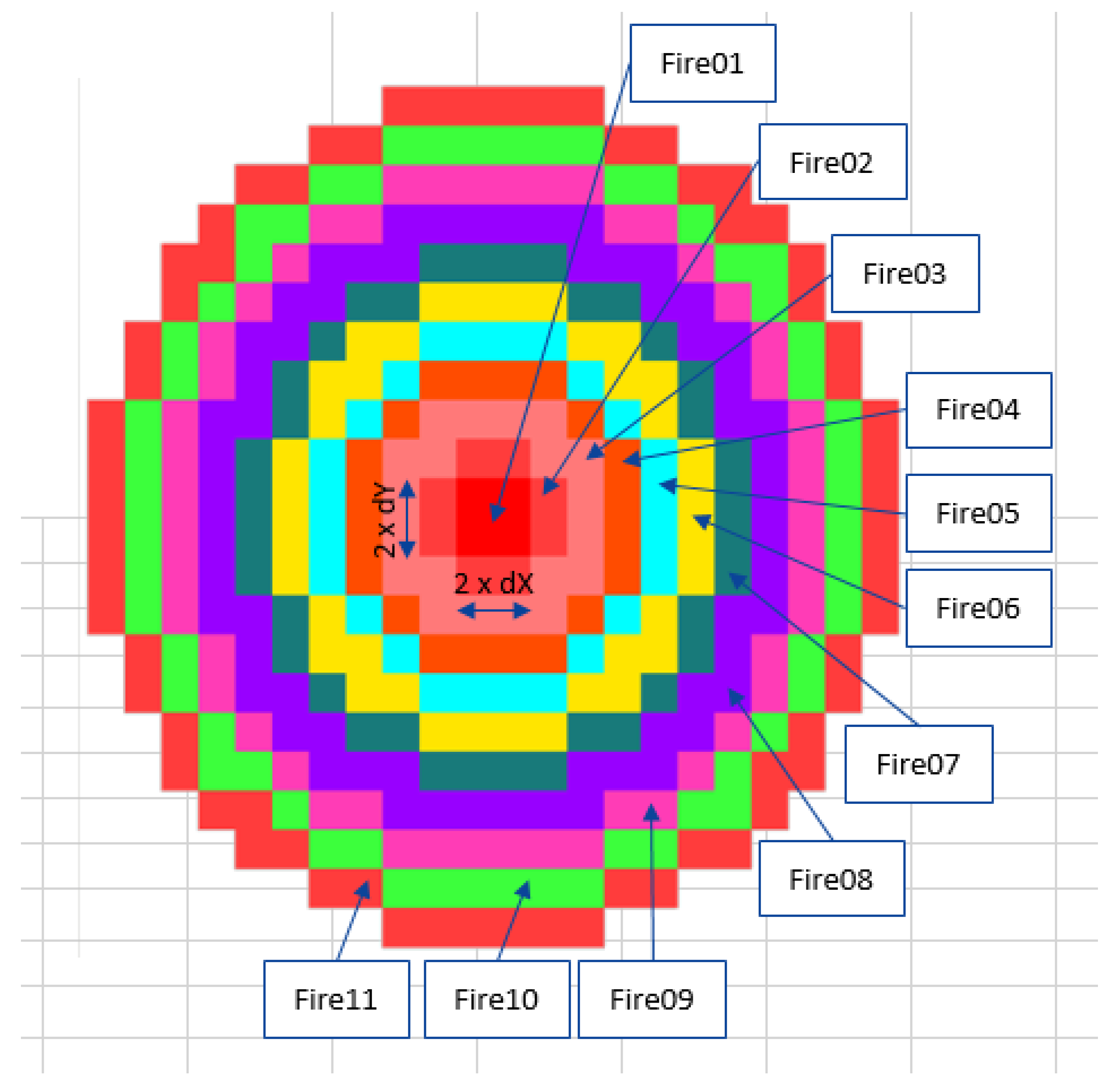
Given the hexahedral mesh used in Pyrosim, obtaining a perfect circle with the exact required diameter is not possible. To achieve as close to a circle as possible, a bespoke spreadsheet has been used to generate a close approximation of a circular fire with the appropriate diameter, where each of the heat release rates of the various rings sum to provide a total fire size equal to 3 MW. Generating a fire using this method leads to the closest that an FDS fire can mimic a circular profile. The makeup of the fire used within FDS is shown below in
Figure 1.
Sprinklers are required in buildings over 25 m in Australia but have been omitted from this simulation. In the event of the failure of a sprinkler system, it is defined as the worst-case scenario. When sprinklers do activate, data show that they will suppress a fire prior to the onset of untenable conditions in most cases. The fire will grow and reach a peak of 3 MW, where it will remain constant for the duration of the simulation. Fires typically decay after this point or are suppressed by the sprinkler system provided but it is not proposed to model the case in which sprinkler failure occurs as the worst-case scenario.
2.2. Supply Air Quantities
To determine the exact supply air requirements in each of the two scissor stairs provided, some trial and error is required, as there is no one-size-fits-all solution to achieve the required flows implemented by AS 1668.1. Supply vents were placed at regular intervals every three storeys at a rate of 2 m3/s. An initial simulation was undertaken using the commissioning requirements of AS 1668.1 to show that the flow rate through the door complied with the requirements of the standard, that is, that it achieves an average flow speed across the door of 1 m/s with two doors open. The model will be run as part of a commissioning study. Since the stair would pass testing in a real-life scenario, it will be considered that this is an appropriate base case design. The simulation uses a soot value of 0.07 kgsoot/kgfuel to provide an appropriately conservative result that is in line with most furniture items.
The flow rates and supply vent locations will be kept constant throughout all simulations regarding stair pressurization systems, with the only variable being the number of doors open into the shaft at any one time. Ambient temperature has been taken as 20 degrees Celsius, with gravity, outside pressure, and other values being taken at ground level.
2.3. Simulation Characteristics
All simulations were run for 300 s, a time deemed suitable to accommodate for evacuation times expected in most cases. Conditions after occupants have left the building are not relevant from a life safety perspective, and the number of doors open into the shaft will drop back down to zero.
The flow rates and supply vent locations are kept constant throughout all simulations regarding stair pressurization systems, with the only variable being the number of doors open into the shaft at any one time. The event timeline for the model is as follows.
At time 0 s, all doors are closed and a fire initiates from an unknown source within the dwelling.
At time 60 s, the doors open within the tenancy, simulating the time at which occupants of that dwelling decide to leave the building.
At time 70 s, the doors within the scissor stairs open, indicating that occupants have made it from the exit. Furthermore, the doors to the dwelling close.
At time 90 s, the doors to the scissor stairs close.
At time 250 s, the doors to both the dwelling and the scissor stairs open for the duration of the simulations.
2.4. Model Construction
The model is constructed as close as achievable to BCA requirements. BCA Clause D1.4 mandates that the maximum travel distance from the entrance door from an apartment to the fire stair does not exceed 6 m. BCA Clause D2.6 states that the maximum length of a corridor may be no more than 40 m and BCA Clause D1.5 states that no two exits may be located closer than 9 m from one another. The height of all ceilings was modeled as 2.75 m, as is typical for apartment blocks constructed today to have head heights of between 2.5 m and 3 m. The height of all doorways was modeled as 2 m, as BCA clause D1.6 requires that the unobstructed height of any exit or required path of travel is at least 2 m [
12].
Table 1 presents the dimensions of the building and demonstrates that all parameters meet the requirements of the BCA.
A scissor stair is provided within the model as two exits are required from any area in buildings featuring an effective height of over 25 m. A scissor stair is the most space-effective way of providing multiple exits, as well as allowing design flexibility. It is noted that there is no physical connection between the two stairs within the shaft as they are separated by fire-rated construction.
Sprinklers are required in buildings over 25 m in Australia as per BCA specification E1.5 but have been omitted from this simulation, as the failure of sprinklers to operate encompasses the worst-case scenario. When sprinklers do activate, data show that they will suppress a fire prior to the onset of untenable conditions in most cases. Leakage has been modeled through all doors through holes located in the geometry, with values recommended by Gross [
13].
Smoke detectors and heat detectors have been modeled down the corridor, to accurately measure temperature for the purposes of conducting a mesh dependency study. This configuration is as close to Deemed-to-Satisfy (DtS) provisions are reasonable to achieve and the only differing factors between input files will be the smoke control systems provided and the number of doors open. The extent of the model can be found below in
Figure 2 and
Figure 3.
2.5. Verification
A large amount of validation work has been undertaken by the NIST and is detailed in the Fire Dynamics Simulator Technical Reference Guide [
14]. This work has included a verification of the turbulence model, the basic flow model, boundary effects, heat transfer, and a few other important areas.
Verification of a model involves reducing the amount of error to the lowest practical amount. This typically requires the use of a mesh dependency study, examining convergence, and comparing results. In CFD simulations, a grid is required, and the resolution of this grid directly impacts accuracy as well as simulation time.
The model used for the mesh dependency study features two doors open per shaft, complying with the testing requirements set out in AS 1668.1. The model will also feature a fire, allowing results for temperature, visibility, fractional effective dosage, and airflow to be compared with respect to grid resolution.
The grid size will then be halved until a suitably accurate mesh is uncovered. See
Table 2 for the
, of each of the proposed meshes. It is noted that both the 0.25 m × 0.25 m mesh and the 0.125 m × 0.125 m mesh have
values lying between 4 and 16, complying with guidance found within the FDS technical reference [
14].
Two parameters, i.e., Fractional Effective Dosage (FED) and visibility are presented in
Figure 4 for verification of the study. FED within the corridor has been compared at various mesh sizes to determine how the resolution of the grid used affects the results obtained. Results of FED values for mesh sizes 0.25 m × 0.25 m × 0.25 m and 0.125 m × 0.125 m × 0.125 m have been plotted against time on the same axis for a direct comparison (refer to
Figure 4a). It is clear through analyzing
Figure 4 that there is a slight variance between the FED values found in the coarse and tight mesh. The results, however, tend toward one another, becoming almost exactly equal by the end of the simulation. Since FED is a compounding value, the most important result is the maximum value. If the results both tend toward the same value regardless of mesh sizing, it is to be considered that mesh sizing above 0.25 m × 0.25 m × 0.25 m does not have a significant impact on FED. In
Figure 4b, the visibility values within the compartment of fire origin at two mesh sizes as mentioned earlier were compared for verification purposes. It is clear that there is no appreciable difference between the results where visibility is concerned. Both meshes show a trend of initial visibility value at 30 m and the same pattern of decrement as time progresses.
3. Results
This study examines the performance of stair pressurization systems with various numbers of doors open into the shaft, i.e., 2, 4, 6, 8, and 10 doors. All simulations were undertaken for 300 s. For the purposes of clarity, the simulations have been split into four phases, consisting of:
Simulation begins, fire ignites, and no doors are open.
Doors to the stairs open initially at 70 s, remaining open for 20 s.
Doors closed; smoke has entered the corridor.
Doors to the stair shaft reopen and at t = 250 s and remain so until the conclusion of the simulation.
Table 3 presents all of the simulated cases, indicating that in all cases, both the door at the floor of the fire origin and the ground floor are open at all times. There is no fire event in the commissioning case. The floors adjacent to the floor of the fire origin, which is located at the mid-level of the building (refer to
Figure 2a,b), are then open according to the increase in the number of doors open.
3.1. Commisioning Case
In the commissioning case, there is no fire provided. The only feature of the model is an air injection provided to the stair shaft. A single door at the floor of interest and another door on the ground floor are open into the stair shaft. This configuration complies with the commissioning requirements as set out in AS 1668.1. As results show that flow speeds average through the door in the model comply with Australian legislation, the same vent configuration and supply flow rates will be used throughout all stair pressurization models. By keeping the flow rates at the sample level, it will be clear how a system that may be commissioned in a non-fire event will perform in an actual fire. Since there is no fire in this simulation there will be no byproducts of fire produced; as a result, there is no need to measure temperature, visibility, or fractional effective dosage and these results have been omitted.
Between the simulation start at time zero and the time at which the doors are opened for the first time, flow through the door tends toward 0.5 m
3/s. This is representative of the amount of air leaking through the door via the simulated cracks. The volume flow rates tend toward a constant amount during this time and reach it at approximately 40 s. At time 60, when the doors open for the first time, there is an initial fluctuation of flow on both floors, but these fluctuations correct themselves and the flow rates through the door appear to settle towards a flow of 2.5 m
3/s in both doorways. It does appear that there is not enough time for the flow to reach a steady state given the amount of time the stair doors are open for. Between time 70 and time 250, where the doors have closed again, the results tend towards the same value of 0.5 m
3/s, as found at the beginning of the simulation, and there is more than ample time available to reach this steady state. Between the time of 250 s until the completion of the simulation when doors open again, there is an initial fluctuation but the volume flow through both stairs settles at a relatively stable amount. Interestingly, the two stairs do not settle at an equal value. This is because the ground floor stair inlet shaft serves four stories, while the inlets above only serve three stories each, meaning there is some additional leakage from cracks on the floors above. As shown in
Figure 5, flow through both the door of interest and the ground floor door achieve volume flow rates of 2.4 m
3/s and 2.6 m
3/s averaged across the entirety of the door frame, respectively, when the doors are both open simultaneously. Given that the door has an area of exactly 2 m
2, the flow speed through the area can be simply calculated as above 1.2 m/s and 1.3 m/s, respectively, complying with the flow speed requirement of 1 m/s within the Australian standards. Given that the flow speeds through the shaft comply with the requirements of the Australian code, it is concluded that this system would pass commissioning in a real-life scenario, making it suitable for use in all the following simulation cases, without adjustment.
3.2. 2 Door Open
The model used during this simulation has geometry exactly equal to that found in the commissioning case above and features identical control logic for doors, with only two doors opening into the shaft at once at any time. In this simulation, however, a fire has been placed within the mid-level of the modeled apartment. The fire begins at the rest of the time, t = 0 s, and grows quadratically until reaching a peak value.
As a by-product of the fire, smoke and heat are added to the environment and spread throughout the domain. As smoke fills the corridor it will attempt to move into the stair shaft, but the stair pressurization system provided, complying with the commissioning requirements is designed to prevent the ingress of smoke into the safe space. The volume flow rates through the doors of interest are presented below in
Figure 6.
At time t = 0, the simulation begins, and airflow is initiated through the inlets within the stair shaft. At time t = 5 s, the flow rate through the small cracks in each door has reached equilibrium and remains a constant at 0.53 m3/s until time t = 70 s. At time t = 70 s, the doors on both the floor of fire origin and the ground floor open completely and remain this way for 20 s. During this time air flow through both doors reach a spike equally to a maximum of 2.5 m3/s and remains at this magnitude, with minimal oscillation for the duration of time the doors remain open. From time t = 90 s to t = 250 s when all doors are now closed again, the airflow through the cracks tends towards the same values as previously. At time t = 250 s, the doors to both stairs reopen. By this time there is a considerable amount of smoke in the corridor adjacent to the stair shaft and then, as a result, the area is at a relatively high pressure. The flow through both the stairs at the ground floor and the floor of origin settle at 2.4 m3/s and 2.5 m3/s of flow, respectively. The difference in flow between floor levels is likely caused by air flowing and the fact that the inlet closest to the ground floor serves an additional storey in comparison to the inlets above.
Comparing the results of flow out of both stair shafts while the door is open the flow speed averaged across both doors satisfies the requirements as set out by the Australian standards, with a recorded flow speed of 1.25 m3/s on the floor of fire origin. Given this, it is expected that the system would perform as required, preventing the ingress of smoke into the shaft.
3.3. 4 Door Open
Similar to the model with two doors open into the stair shaft, the geometry, fire, devices and control regimes are equivalent to the previous models simulated, with the sole difference being that now four doors into the stair shaft will be open at any one time. This case would represent a building operating on a one up one down phased evacuation strategy, where the floor of the alarm and the floors immediately above and below are evacuated simultaneously while other floors are informed to wait. The volume flow rates through the doors of interest are presented in
Figure 7.
At time t = 0, the simulation begins and airflow is initiated through the inlets within the stair shaft. At time t = 5 s, the flow rate through the small cracks in each door has reached equilibrium and remains constant at 0.2 m
3/s until time t = 70 s. At time t = 70 s, the doors on both the floor of fire origin and the ground floor open completely and remain this way for 20 s. During this time air flow through both the ground floor and fire floor spiked to 2.1 m
3/s and 1.2 m
3/s, respectively. The flow fluctuates considerably during this period of time and does not settle on a particular value before the next phase. The flow through these doors is substantially different than found in the previous simulation, when compared to
Figure 6. The fluctuation is likely to the stair shaft and corridor having substantially different pressure profiles, since now the shaft is of higher pressure than the corridor as no smoke has entered. From time t = 90 s to t = 250 s when all doors are now closed again, the airflow through the cracks tends towards the same values as in phase 1. At time t = 250 s, the doors to all four stairs reopen. By this time there is a considerable amount of smoke in the corridor adjacent to the stair shaft and as a result the area is at a high pressure. The flow through both the stairs at ground floor and the floor of origin settle at 0.6 m
3/s and 1.4 m
3/s of flow, respectively. The drop in flow rates when compared to the previous scenario is over 40%, showing that a significant drop occurs once the design scenario is exceeded. The difference in flow between floor levels is likely caused due to the additional storey served by the inlet supplying air to the ground floor, which is now open in this configuration, allowing a substantial amount of air to flow into that corridor instead of the ground floor.
Comparing the results of flow out of both stair shafts while the doors are open, the flow speed averaged across both doors does not exceed the levels mandated by AS 1668.1, with a flow speed of only 0.7 m3/s in lieu of 1 m3/s. Given that the results are below Australian requirements, it would be expected that there is at least some leakage into the stair shaft.
3.4. 6 Door Open
This case would represent a building operating on a two up two down phased evacuation strategy, where the floor of alarm and the two floors immediately above and below are evacuated simultaneously while other floors are informed to wait. The volume flow rates through the doors of interest are presented in
Figure 8.
At time t = 0, the simulation begins and airflow is initiated through the inlets within the stair shaft. At time t = 5 s, the flow rate through the small cracks in each door has reached equilibrium and remains a constant 0.2 m3 until time t = 70 s. At time t = 70 s, the doors on both the floor of fire origin and the ground floor open completely at remain this way for 20 s. During this time the flow through the door on fire level peaks at a flow of 2 m3/s from the stair to the shaft, and 1 m3/s from the corridor into the shaft. This is considerably different from the previous simulations, as now the air is flowing in the opposite direction on the ground floor. Like the previous simulation, the flow rates for both the floor of fire origin and the ground floor continue to oscillate for the remainder of this phase. From time t = 90 s to t = 250 s when all doors are now closed again, the airflow through the cracks tends towards the same values as found in the initial phase. At time t = 250 s, the doors to all 4 stairs reopen. By this time there is a considerable amount of smoke in the corridor adjacent to the stair shaft and the as a result the area is at a high pressure. The flow through both the stair at the ground floor and the floor of origin fluctuates considerably before settling at 0.4 m3/s and 1.2 m3/s of flow, respectively. The flow rates through both the ground floor and the floor of fire origin are considerably lower than found in the 4-doors configuration, with a 33% drop in flow through the ground floor opening, and a 21% drop in flow through the floor of fire origin.
The flow rates through the floor of the fire origin drop to as low as 0.6 m
3/s in lieu of 1 m
3/s. This suggests that this system may not perform as designed with this many doors open. This is supported by the visibility slices in
Figure 9, which show significant smoke ingress into the stair. there is smoke leaking into the staircase, reducing visibility to as low as 5 m within the doorway. Thus, it appears as though the stair pressurization begins to allow large quantities of smoke within a stair once airflow through the door of fire origin drops to a speed of 0.55 m/s or below.
Toxicity does increase past zero, to the highest amount of all simulations, but the results are nowhere near exceeding the FED tenability limit of 0.3, with a maximum recorded value of 0.000247. FED values only begin to increase at 260 s, corresponding to the point when smoke initially enters the stair as per
Figure 10.
3.5. 8 Door Open
The flow rates through the door of fire origin and ground floor for eight-doors open case are plotted in
Figure 11.
At time t = 0, the simulation begins, and airflow is initiated through the inlets within the stair shaft. At time t = 5 s, the flow rate through the small cracks in each door has reached equilibrium and remains a constant 0.2 m
3/s until time t = 70 s. At time t = 70 s, the doors on both the floor of fire origin and the ground floor open completely at remain this way for 20 s. During this time the flow through the door on fire level peaks at a flow of 1 m
3/s from the stair to the shaft, and 1.5 m
3/s from the corridor into the shaft. This is similar to the simulation where 6 doors are open, but the peak flow on the ground floor is higher. This is likely due to air flowing into the stair from an additional 2 floors, and leakage from all inlet points into the other stories prior to the air making it to the floor it is required. From time t = 90 s to t = 250 s when all doors are now closed again, the airflow through the cracks tends towards the same values as the beginning of the simulation. At time t = 250 s, the doors to all 4 stairs reopen. By this time there is a considerable amount of smoke in the corridor adjacent the stair shaft and the as a result the area is at a high pressure. The flow through both the stair at ground floor and the floor of origin settle at 0.1 m
3/s and 1.1 m
3/s of flow respectively. The change from the previous simulation, seen in
Figure 7 with four doors open is small, with less than a 5% deviance in flow through both doors of interest.
Neither the flow through the ground floor stair nor the flow through the stair at the fire origin comply with the flow requirements set out by the Australian code, with a speed through the door of 0.55 m/s in lieu of 1 m/s as expected; smoke leaks into the stair due to the inadequate barrier created. This leakage can be seen in
Figure 12.
Figure 12 clearly shows significant leakage into the stair shaft. The visibility within the stair is the lowest of all simulations up to this point, suggesting a continued trend between a decrease in flow through the stair of fire origin, and visibility in the stair shaft. Toxicity does increase past zero, to the highest amount of all simulations, but the results are nowhere near exceeding the FED tenability limit of 0.3, with a maximum recorded value of 0.0003. FED values only begin to increase at 250 s, corresponding to the point when smoke initially enters the stair as per
Figure 13.
3.6. 10 Door Open
A model has been constructed which features all doors within the model open at a single time. This would be indicative of a building using a simultaneous approach to evacuation. Flow rates through the door are depicted in
Figure 14.
At time t = 0, the simulation begins and airflow is initiated through the inlets within the stair shaft. At time t = 5 s, the flow rate through the small cracks in each door has reached equilibrium and remains a constant at 0.5 m3/s until time t = 70 s. The flow rate through each of the cracks is higher than any of the previous simulations undertaken. It is not apparent why the flow rate through the cracks tends toward a higher value in this simulation, as prior to the doors opening, there is no difference in this simulation to others undertaken. At time t = 70 s, the doors on both the floor of fire origin and the ground floor open completely and remain this way for 20 s. During this time the flow through the door on fire level peaks at a flow of 1.25 m3/s from the stair to the shaft, and 1.5 m3/s from the corridor into the shaft. This is similar to the simulation where eight doors are open. Similar to the other simulations undertaken, there are consistent oscillations throughout this phase and a constant value is never reached. From time t = 90 s to t = 250 s when all doors are now closed again, the airflow through the cracks tends towards the same 0.5 m3/s value. At time t = 250 s, the doors to all 10 floors reopen. By this time there is a considerable amount of smoke in the corridor adjacent to the stair shaft and as a result the area is at a high pressure. The flow through both the stairs at the ground floor and the floor of origin settles at 0.1 m3/s and 0.9 m3/s of flow, respectively. As expected, these flow rates are the lowest recorded through all simulations.
The effectiveness of the stair pressurization system to preventing smoke ingress with all doors open is shown below by a visibility slice in
Figure 15.
Figure 15 clearly shows a significant leakage of smoke from the corridor into the stair shaft, with visibility dropping down below 15 m in the left-most shaft. This is expected as flow within the shaft drops below 0.45 m
3/s in lieu of the 1 m
3/s required. Visibility is still higher but occupants entering the stairs from the floor above may be deterred by smoke in the stair, assuming that the area is compromised.
Toxicity does increase past zero, to the highest amount of all simulations but the results are nowhere near exceeding the FED tenability limit of 0.3, with a maximum recorded value of 0.0012. FED values only begin to increase at 250 s, corresponding to the point when smoke initially enters the stair as per
Figure 16.
3.7. Comparison
Figure 17 summarizes the general trend of flow rates through the two doors of interest as the number of doors into the shaft increases. The results for all simulations undertaken show a clear trend in the reduction of flow rate as the number of doors into the shaft increases. The most significant drop-in flow rate occurs between the situation of two doors open into a shaft and four doors open into the shaft, with a drop-in flow rate of over 40%. This significant change is likely down to the fact that the injection points of air are only located every three levels and as a result, once four doors are open into the shaft the supply air has to be split amongst additional stories, allowing air which would have previously reached the required floors to leak out onto other stories. This reduces the total amount of air that flows through each individual storey considerably. For openings into the shaft that are greater than four, changes between each individual iteration become minor. The reason this change is minor is because the air flowing through each door is already split between three storeys, so the addition of another storey only leads to a minor reduction.
4. Conclusions
Smoke control is one of the most important considerations in building fire safety, i.e., ensuring occupants leave a building safely and in a timely manner during a fire scenario. This work aims to assess differences in possible methods for smoke control in high-rise residential buildings. A review of the literature surrounding smoke control has been undertaken and suggested that current methods for tall buildings are inadequate or unreliable, often not performing how they were originally intended to. The current review also revealed that smoke inhalation and poisoning was the number one cause of death in fire scenarios, suggesting that maintaining tenable conditions in a building is a crucial factor to reduinge the number of deaths. The new dilution or common corridor system that sees a small amount of usage worldwide aims appears to be able to improve tenability in buildings while also having inbuilt redundancies and providing space savings.
This review of the literature has also uncovered a fundamental gap between the way stair pressurization systems are commissioned and their configuration in a realistic fire scenario. This gap lies in the fact that only two doors must be open to a stair during commissioning, but a considerable amount more may be open as multiple floors of people leave their units. The notion of only having two stairs open at a time is designed to simulate fire brigade members entering the building on the ground floor and opening a single door to the floor that is originally on fire. This leads to a scenario in which the system is not designed in a way that matches realistic scenarios, and requirements of the standards have not changed as the heights of buildings have increased. These systems may provide additional time for occupants at the greatest risk additional time to evacuate the building. However, any additional evacuation time provided by these systems may not necessarily justify deviances from the DtS requirements of the BCA. Further research is needed to determine how these systems perform, especially from a reliability perspective.
Through research, review and simulation, several potential issues were raised. Given the results of the mesh dependency study and data from NSIT, it is proposed that the results obtained are still satisfactorily accurate. The trends uncovered after simulation work conformed well to initial expectations, with door flow rates decreasing in each successive scenario, as the number of doors into the stair shaft increased. It was however noted that the most significant drop in flow rates occurred between the two-door and four-door cases, with a drop in the flow rate when over 40%. This significant change is likely due to the fact that the injection points of air are only located every three levels and as a result, once four doors are open into the shaft, the supply air has to be split amongst additional stories, allowing air which would have previously reached the required floors to leak out onto other storeys.
The simulations undertaken have shown that the stair pressurization system begins to fail when more than four doors are open into the shaft at any one time. This is a credible scenario for egress in tall buildings, where it is common to adopt a ‘two up one down’ approach for evacuation, where occupants from the fire floor, the two floors above and the floor below, are all given an evacuation tone simultaneously. The number of doors open into the shaft will also increase as occupants on other floors begin to leave, either by the alarm system cascading upwards, or fearful occupants leaving as soon as they are provided with an alert tone. The exact amount of airflow required to prevent the ingress of smoke has been deemed by this report to be above an average flow speed of 0.7 m/s. To account for the unique evacuation strategies used within each individual building, the stair pressurization systems must be designed to perform adequately in an emergency event. This means that the flow speed should never drop below 0.7 m/s in any credible scenario. Designing a system to comply with this requirement may end up costing the design team and the developer additional money, but the benefits to human safety are of the utmost importance.
The results of this work suggest that at the very least, the standards regarding the commissioning of stair pressurization systems should be updated to account for realistic evacuation scenarios, based on the evacuation strategy adopted by a specific development, including how the system is set to cascade, the number of stories and the expected evacuation time. Changes to the standards would ensure that systems perform as intended in credible scenarios. This is supported by the fact that smoke begun to leak into the stair once four doors were open, and the largest drop-in flow rate through the door was between the two-door and four-door open cases.
It is however expected that the performance of currently designed stair pressurization systems would continue to degrade as buildings become taller, as the possibility of additional doors being open increases as the number of total stories increases. Given that a system complying with the Australian requirements for commissioning may not perform as expected in a real life fire scenario in a building adopting a “two up one down” type evacuation strategy, becoming more common in buildings exceeding 25 m in effective height, it is clear that there needs to be an update to the requirements for a system to be commissioned. These requirements could include the requirement for the mechanical engineer designing the system to take into account the proposed evacuation methodology to be used, i.e., if a building is to be evacuated three storeys at a time, the requirements for flow should be 1 m3/s through four doors instead of through simply two. Another possible change could include designing the system to require a higher speed, while adopting the same commissioning style. This would be in line with the current New Zealand building code which requires achieving an average flow of 2 m3/s instead of the 1 m3/s required by Australian codes.


