

Experimental Study on Fire Suppression of the Outdoor Oil-Immersed Transformer by High-Pressure Water Mist System

School of Building Environment Engineering, Zhengzhou University of Light Industry, Zhengzhou 450001, China
*
Author to whom correspondence should be addressed.
Fire 2023, 6(6), 238; https://doi.org/10.3390/fire6060238
Submission received: 11 May 2023
/
Revised: 2 June 2023
/
Accepted: 12 June 2023
/
Published: 15 June 2023
(This article belongs to the Special Issue Fire Extinguishing Agent and Application)
Abstract
:Fire accidents due to oil-immersed transformers seriously threaten the safe operation of power systems. In this paper, the similarity principle was used to design a high-pressure water mist fire-extinguishing test platform for a small-scale transformer fire, and the design method achieved a good fire extinguishing effect. The results indicate that a deflagration phenomenon, lasting about 2–4 s, could be observed after activating the high-pressure water mist system; the flame temperature rose rapidly at first, then dropped sharply, and finally cooled to the indoor temperature. The nozzle’s flow rate in this system has a significant impact on the fire extinguishing time. Meanwhile, the adjustment of the upper nozzle height also influenced the fire suppression effectiveness of the system, where a height of 1800 mm achieved the best performance compared to the others. In addition, the ambient wind speed is a very unfavorable factor for transformer fire suppression, where the fire extinguishing efficiency decreases rapidly with the increase in wind speed. Therefore, under low wind speed conditions, the high-pressure water mist system has great advantages in the fire suppression of outdoor oil-immersed transformers, and the above research results can provide a reference for the optimization design of this system.
1. Introduction
The substation is the most centralized place of the power system infrastructure. Nowadays, it is faced with notable fire risks [1,2,3]. According to the statistics [4], the probability of transformer fire accidents in China was about 0.01~0.03% over the past twenty years and has taken on a rising tendency. For example, in April 2018 [5], a sudden breakdown of the high-end Y/D-B phase of the converter transformer at Tianshan Converter Station resulted in a severe fire accident. In November 2019 [6], one person died and two were injured in an explosion and fire at the Jinan substation. When oil-immersed transformer fire accidents happen, the internal insulation oil will constantly leak out and then give rise to various types of fires, such as jet fires, flowing fires, and pool fires, because the position of the oil pillow is higher than that of the transformer body [7]. The transformer fire possesses features of fast propagation speed and high combustion intensity, easily causing great property losses and casualties [8,9,10]. Therefore, it is of great significance to continually enhance the fire-prevention and fire-extinguishing capacities of the oil-immersed transformer.
Over several decades, many researchers have conducted many studies in this field. Chen [11] proposed that there were five main causes leading to transformer fire accidents, i.e., bushing malfunction, winding short circuit, iron core spoilage, deterioration of insulation oil quality and natural disasters. Additionally, the study of small oil pool fires was the most popular method to analyze the combustion characteristics of the transformer oil in terms of the initial oil temperature [6,12,13], the fire source power [14], the size of the oil pool [15,16,17,18,19], the level of oil pool [20], the burning rate [21], the ignition mode [22], the pulsating characteristics of the flame [23,24], etc. However, the transformer fire is a collection of multiple fire scenarios, and the burning rule obviously changes with its geometric scale. Thus, only studying the oil pool fire is not sufficient enough, as it cannot express stereo-burning characteristics.
Moreover, according to the “Standard for Design of Fire Protection for Fossil Fuel Power Plants and Substations” (GB50229-2019) [25], water spray systems, foam spray systems, oil discharge and nitrogen injection systems, and water mist systems are four conventional extinguishing systems used on transformer fires [26,27,28].
For water spray systems, the emitted water droplets can rapidly absorb a lot of heat around the transformer, and the formed water vapor that follows can isolate the insulation oil from the air and play a role in suffocating the fire [29,30]. However, compared with other fire suppression systems, it needs to consume a large amount of water. Many power substations are usually located in drought-affected areas far away from cities and towns, and thus, this limits their applications.
The foam spray system is similar to the water spray system, which can quickly reduce the temperature of the transformer fire by virtue of the endothermic effect of water mist and foam. In addition, the foam extinguishing agent can produce a layer of flame retardant film on the surface of the protected material, obstructing its contact with air and effectively preventing re-ignition [31]. However, the shortcomings of this system are its high operational costs, prolonged response times, pollution environments, and not working well under cold or harsh conditions [32,33].
Moreover, the oil discharge and nitrogen injection systems are also widely used to extinguish transformer fires. They comprise an automatic device that connects its fire detection ability with an alarm and that has oil discharge and is explosion proof and that employs nitrogen injection for fire prevention [34]. The benefits of this system include reliable operation, easy installation and continuous automatic detection [35]; however, when the transformer fire progresses to a stage of fierce combustion, this system cannot function properly or be used well in the event of transformer oil spillage and subsequent combustion outside the confines of the transformer body [1].
Based on the above analysis, the three firefighting systems have some deficiencies in terms of their firefighting efficiency, cost-effectiveness and adaptability to harsh environments [36]. Under the new circumstances, the water–mist system is gradually applied to the oil-immersed transformer fire, which is more friendly, more efficient and more water-saving than other systems [31]. The system can be classified into two types based on the outlet water pressure: the low-pressure water–mist system and the high-pressure water mist system [37]. The low-pressure water–mist system (NFPA750 standard) is characterized by a droplet cumulative volume distribution of DV0.99 < 1000 μm at a distance of 1 m from the nozzle and operating pressure of approximately 1–2 MPa [38]. The primary distinction between the low-pressure water–mist system and the water spray system lies in the nozzle, while other components remain largely unchanged. Therefore, the former also demands a large consumption of water. However, the high-pressure water mist system, also known as micro water droplets, is primarily based on a positive displacement pump that can generate the water mist with a DV0.99 < 200 μm. The outlet water pressure must be greater than 10 MPa and can even reach a maximum of 100~200 MPa. The working pressure is usually 10~20 MPa in practical engineering applications, considering safety, economy and efficiency factors.
In terms of the extinguishing principle, the low-pressure water–mist system is similar to the water spray system, which has the characteristic of surface cooling, oxygen isolation and asphyxia, radiant heat isolation, smoke suppression and immersion wetting [39]. However, the high-pressure water mist system is fundamentally different from the low-pressure water mist system or the water spray system in terms of the pressure formation principle and the flow control way of the system. Its extinguishing mechanism is as follows [40,41]: (1) Better endothermic effect. Because the relative surface area of the discharge water mist droplet can attain a 1700-times larger size than that of the spray water droplet from the low-pressure system, it can completely evaporate in the fire site. (2) More effective suffocating effect. After ejecting, the water–mist rapidly evaporates into vapor, expands its volume and excludes the air, finally forming a barrier around the burning fuel to prevent the inhalation of fresh air. (3) Hindering radiant heat. The water vapor quickly envelops the flame, which has a more excellent ability to hinder radiant heat and can effectively suppress the radiant heat igniting other items nearby.
Nevertheless, the high-pressure water mist system also has its own inherent defects. For example, fine water mist particles are easily affected by external factors, such as environmental wind. Therefore, the system is mostly applied to fire suppression in enclosed spaces. In this paper, through the real test of simulating an oil-immersed transformer fire, the feasibility of the outdoor application of the high-pressure water mist system, especially in a bad environment, is studied.
2. Methodology
2.1. Design Principle
In general, the design of a fire suppression system not only considers the fire situation of the protected object, such as the fire characteristics, space geometry, environmental conditions, etc., but it also follows the related standard, taking into account safety and economy.
Due to the variety of water mist products and the complexity affecting their extinguishing effectiveness, the research, design and application of the water mist fire suppression system is always based on the real-fire simulation test. The NFPA 750 standard does not provide specific parameters but requires the relevant fire test to determine them [38].
The oil-immersed transformer fire has dual characteristics of both electric and liquid fires because the transformer is the power equipment, and the fire source is the insulation oil that can flow. Furthermore, the high-pressure water mist system is highly effective in extinguishing electric and liquid fires due to its outstanding extinguishing character. At present, the design principle of the system is based on the national standard “Technical Code for Water Mist Fire Extinguishing System” (GB50898-2013) [42], which is a technical specification for the water mist system in China. The flow discharge coefficient, K, is one of the main technical parameters, which can be calculated using the following formula [43]:
where Q is the flow rate of a nozzle, L/min. P is the operating pressure of a nozzle, MPa. K is the flow discharge coefficient of a nozzle, L/min/Mpa0.5, which is provided by the manufacturer.
where N is the total number of nozzles. S is the effective protection area, m2. W is the water spray intensity, L/(min·m2).
According to the state standard [42], this system’s design should prioritize the following five basic principles:
- The layout of the water mist nozzle is generally based on the rectangular shape.
- The emitted water mist should be evenly distributed to fill the protective space and completely shield the protected object.
- The working pressure P at the worst place must be no less than 10 MPa.
- The water spray intensity W must be no less than 1.2 L/(min·m2), and the water consumption should not be overdone.
- The flow discharge coefficient K should be within the design domain of the manufacturer.
Other parameters, such as the nozzle spray spacing and installation height, etc., can be appropriately adjusted as required; however, this needs to be illustrated. The minimum distance between the nozzle and the protected object should achieve good atomization, while the maximum distance should ensure that the water mist has enough impulse to reach the surface of the protected object [44].
2.2. Problem Analysis
Obviously, it is extremely difficult to conduct a high-pressure water mist system test for real and large-scale transformer fires due to the inconvenience of the equipment transportation, the high economic cost and the uncertainty of the experimental fire risk, etc. Meanwhile, the larger the size of the transformer body is, the greater its oil reserve is, and the more difficult the fire control is. Thus, in this paper, we propose to use a small-scale transformer instead of the large-scale one to evaluate the extinguishing effectiveness of the high-pressure water mist system.
There were two primary methods for designing the experiment platform. One was to calculate directly according to the national standard above, and the other was to calculate indirectly based on the principle of similarity.
For the first method [45], initially, the total number of nozzles can be determined according to the geometric size of the device. Then, the flow rate for a single nozzle can be calculated based on Equation (2). Finally, the flow discharge coefficient, K, meeting the standard water spray intensity, can be obtained by Equation (1). As shown in Figure 1, the small-scale transformer in the test was a stereo-rolled iron core transformer of the following model: S13-M-RL-200/10, rated capacity 200 KVA, 10 KV, 3-phase. The geometry size was 1 m × 1 m × 0.82 m, and its outer effective protection area was about 5.05 m2. It was manufactured by the Henan Tianli Electric Equipment Company in September 2016 and has now been scrapped. It is obvious that at least 8 nozzles were placed around the transformer so that the nozzle layout completely covered its outer surface. According to Equation (1) and Equation (2), if the water spray intensity was equal to 1.2 L/min·m2 and the operating pressure of a nozzle was 10 Mpa, the flow discharge coefficient K was 0.07575 L/min/Mpa0.5. However, the K value was too low, which was not in the design range of the manufacturer. Thus, based on the first method, the test design has certain flaws.
2.3. Similarity Design
Compared to the large-scale prototype test, the small-scale fire model test has the advantages of a lower cost, shorter cycle and higher measurement accuracy and has gradually become an important method in substation fire research [46]. In theory, the establishment of the small-scale fire model can be achieved when the similarity parameters of both the prototype and the model are equal. However, it is almost impossible to achieve the exact equality of all characteristic numbers. Therefore, some important parameters are often selected in practice, and it can be considered that when these parameters are equal, the prototype is similar to the model.
In 1973, Heskestad [47] first proposed the application of Froude modeling in fire simulation testing, with the method being widely used because of its good applicability to the small-scale experimental study of fires in open spaces. The necessary condition for the Froude similarity model is that the Reynolds number is large enough to ensure that the flow is turbulent. The related research indicates that the fire flow can fully develop into turbulence as long as the main feature size of the model is not less than 0.3 m [48]. Moreso, in addition to the working pressure and the water flow rate, the system’s flow discharge coefficient K is also related to the particle size, fog particle characteristic quantity, physical momentum, spray angle, range and other parameters. However, because the national standard does not carry out detailed constraints on the latter related parameters, to simplify the study, these content influences are ignored in the paper.
Taking a 220 KV outdoor oil-immersed transformer of the substation in Zhengzhou as a prototype, as shown in Figure 2, the geometric size is approximately 8 m × 7.5 m × 4 m, and the effective protection area is about 240 m2. The design, based on the current standard, is that the layout of the nozzle is arranged as a three-layer frame structure, with 4 nozzles on the top layer and 18 nozzles on the other per layer. The water flow rate of an individual nozzle is 10 L/min. The horizontal spacing between nozzles is 2500 mm, and the vertical interval between layers is 4000 mm. The system’s operating pressure is 10 Mpa. The distance from the nozzle to the transformer is 1500 mm, and the height from the top nozzle to the ground is 6.8 m. The water spray intensity of the system can be calculated as 1.67 L/(min·m2), and the flow discharge coefficient K is 1.0 L/min/Mpa0.5.
According to the similarity principle [49,50], the detailed design parameter between the prototype and the model is shown in Table 1. For example, the proportional coefficient of the water flow rate of a single nozzle is 32, and the water flow rate of the small-scale transformer can be calculated as 0.3125 L/min. Based on Equations (1) and (2), if the water spray intensity is equal to 1.2 L/(min·m2) and the working pressure of the nozzle is 10 MPa, the flow discharge coefficient K can be obtained at 0.03125 L/min/Mpa0.5, and the number of the total nozzles is at least 19. Thus, in this paper, the water mist nozzle is arranged as two layers around the transformer, with each layer having 12 spray nozzles and a total of 24. As shown in Figure 3, the bottom nozzles (about 200 mm above the ground) protect the bottom oil pit (simulated by the bottom oil pan), and the top nozzles (about 1800 mm above the ground) protect the transformer’s body.
3. Experiment Platform
3.1. Platform Building
In general, the development process of the transformer fire can be divided into three stages: the initial growth stage, the stable burning stage and the decay stage [51]. Among them, the second stage is where the combustion intensity is the largest, the temperature rise is the highest, and the diffusion rate is the most rapid. At this point, it is the most difficult period of flame suppression. Furthermore, on the one hand, the oil-immersed transformer fire has flowing, stereo and explosion characteristics, resulting in it being very difficult to conduct a real overflow fire test. On the other hand, as long as the high-pressure water mist system can put out the transformer fire while in the stable combustion stage in a short time, it can be considered that this system has a good effect on the transformer fire. Therefore, based on the above considerations, our group proposes that the real overflow fire was substituted by the multi-point oil pan burning.
The fire extinguishing test was performed in a large-space laboratory, as shown in Figure 4 and Figure 5. The test platform comprised a set of high-pressure water mist systems, a small transformer, eight oil pans, four brackets, several thermocouples, a draught fan and a smoke exhausting system. The high-pressure pump of the system was a portable device and could export a constant pressure of 15 Mpa, as shown in Figure 6. The small transformer was placed on a 0.4 m high channel steel bracket. Eight oil pans were evenly arranged on the transformer to use as the fire source, respectively, with four at the top and the other four at the bottom. Additionally, the diameter of each oil pan was 40 cm. Four brackets were set up around the transformer to measure the ambient temperature: Bracket A#, Bracket B#, Bracket C# and Bracket D#, respectively. They were in the front, left, back and left of the transformer. The spatial arrangement of each bracket is shown in Figure 5. Bracket A# and Bracket B#, respectively, contained seven temperature measuring points, and Bracket C# and Bracket D#, respectively, contained three temperature measuring points, as shown in Figure 7. It should be noted that Bracket D# was used to measure the center line temperature at the top of the transformer. The K-type thermocouple was made of nichrome–nichrome silicon, the measuring range of which was 0~1300 °C. The temperature data were collected every 1 s and automatically saved. In addition, the draught fan, positioned 2 m away from the transformer, was a frequency conversion device used to generate the needed airflow. The large exhaust hood was installed at the top of the testing platform, which was an off-gas treatment device to reduce environmental pollution.
3.2. Experiment Procedure
The experiment was conducted while considering three factors: water flow rate, nozzle height and ambient wind speed. The factor of the water flow rate included adjusting the flow discharge coefficient K of the nozzle and reducing the number of nozzles (blocking the middle eight nozzles with plugs), and the final design result is shown in Table 2. For the nozzle height, as shown in Figure 5, the upper nozzle height (H1) was set to 1400 mm, 1600 mm and 1800 mm, respectively. Additionally, the below nozzle height (H2) always remained unchanged and was 200 mm away from the ground. In addition, due to the instability of the airflow, the average wind speed of the cross-section was taken as the research object at 0 m/s, 0.5 m/s, 1 m/s and 2 m/s.
The test material was 25# transformer oil. As shown in Table 3, during the experiment process, a small amount of gasoline was added as the ignition agent because the transformer oil was not easy to ignite at the indoor temperature. Additionally, a certain amount of water was added to the oil pan bottom, lest the influence of the oil pan wall on the fire extinguishing efficiency of the system.
3.3. Testing Scheme
In this paper, 11 trials were carried out based on the above experiment platform. As shown in Table 4, the fire extinguishing time of the top oil pans, 1#–4#, the bottom oil pans, 5#–8#, and their average extinguishing times were listed, which were key factors in evaluating the extinguishing efficiency of the high-pressure water mist system. The longer the fire extinguishing time is, the worse the fire extinguishing efficiency is.
4. Results and Discussion
4.1. Fire Suppression Process
Figure 8 shows the partial images of the entire flame development process for the typical test, test 5, including the burning phase of the oil pan fire and the firefighting phase of the high-pressure water mist system. Because the stable combustion state had been entered completely after about 80 s of igniting the oil pan fire, we stipulated that the high-pressure water mist system be activated at about 140 s after igniting the oil pan fire. In addition, the ignition moment was taken as the starting point in Figure 8.
Significantly, a deflagration phenomenon lasting about 2–4 s was observed in the initial period of ejecting the water mist. From then on, a large amount of water vapor appeared surrounding the flame. When entering the stable combustion stage, the burning center of the oil pan fire had less oxygen content, generating a large amount of black smoke. That is to say, the fuel at the center of the fire was not sufficiently burned. Once the fire suppression system was activated, the high-speed water mist carrying the fresh oxygen would instantly spray and quickly reach the central position of the burning transformer oil. At that moment, the deflagration phenomenon was induced by full contact between the fuel that was bad at sufficiently burning and the adequate oxygen; the water mist had not had time to vaporize during that moment. However, with the passage of the ejection time and the increase in ejection volume, the water mist vaporization gradually occupied a dominant position. Finally, the transformer oil pan fire was extinguished through surface cooling, oxygen asphyxia, etc.
From a perspective of space, the fire of the bottom oil pans 5#–8# was usually extinguished earlier than that of the top oil pans 1#–4#. There were two reasons for the difference in the extinguishing time: (1) Considering the randomness of the ignition point and the burning process in real-life transformer fires, the jet of the nozzle was directed horizontally rather than sprayed specifically towards a particular oil pan; (2) the spatial arrangement of the top oil pans 1#–4# was more dispersed than that of the bottom oil pans 5#–8#, and the distance between the burning point and the nozzle was also greater. To some extent, the above reasons reduced the extinguishing capability of the top nozzles. Especially for the oil pan at the corner, the extinguishing effect was even worse. However, it did not affect the study of project test results. On the one hand, the occurrence and development of transformer fires in the real environment are more complex and changeable. On the other hand, in the process of analyzing the results, we can discuss, respectively, the changing rule regarding the top and bottom oil pan fires. Based on the above reasons, the impact of multiple factors on the extinguishing efficiency of the high-pressure water mist system can be studied systematically.
4.2. The Temperature Curve of the Typical Test
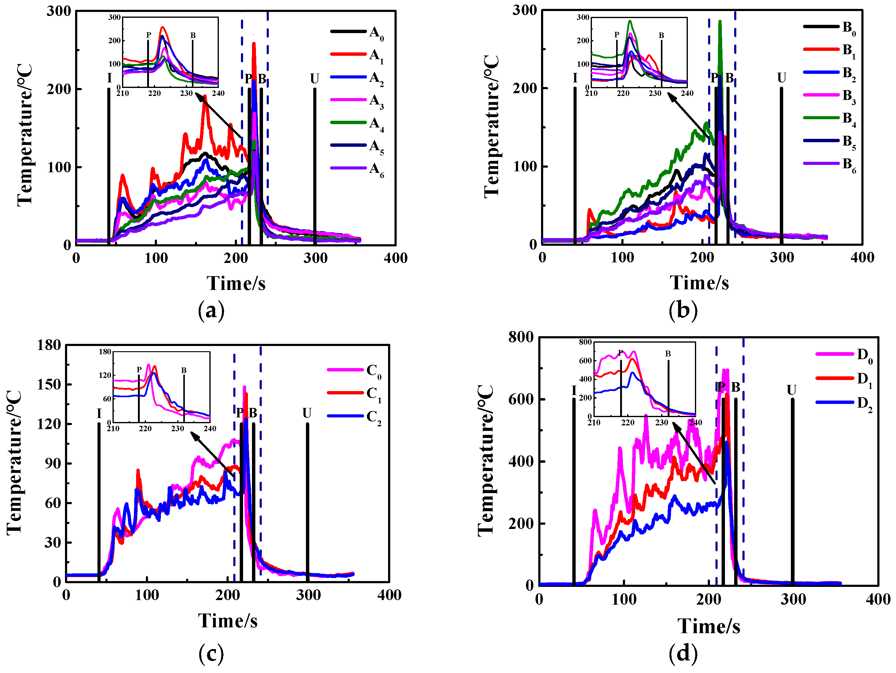
Figure 9a–d displays the temperature curves at different measuring points of Bracket A#, Bracket B#, Bracket C# and Bracket D# before and after activating the high-pressure water mist system for the typical test 5. The letter ‘I’ denotes starting the ignition of the oil pan fire; the letter ‘P’ denotes activating the high-pressure water mist system; the letter ‘B’ denotes the time that the bottom oil pan fire was extinguished; and the letter ‘U’ denotes the time that the top oil pan fire was extinguished.
It was observed that the flame temperature rapidly increased at the initial stage after igniting the oil pan fire and gradually reached stability. After the high-pressure water mist system was turned on, the ambient temperature rose sharply for about 2–4 s. Then, it dropped sharply from 700 °C at the highest temperature to 10 °C at the indoor temperature within about 30 s. As the surrounding temperature was higher during the early stage of the fire suppression, it was easier for the water vapor to form and create an asphyxiating environment around the transformer, thus leading to a rapid decline in the fire environment temperature. However, fire suppression developed later, and there was usually only one oil pan burning. During this time, the temperature around the transformer had been reduced to an ambient level, and it was very unfavorable to form an asphyxiating environment, which also indirectly delayed the fire extinguishing time.
The temperature curves changed consistently with the fire development in Figure 8. It indicates that the high-pressure water mist system has a good extinguishing effect on the transformer oil fire and can effectively control the burning temperature in a very short time. In addition, the temperature at each measuring point was poorly correlated with its height but had a strong relationship with the distance from the fire source. As the distance decreased, the temperature increased.
4.3. The Impact Analysis of Ejecting Flow Rate on Fire Extinguishing Efficiency
Figure 10a,b show the temperature curves and extinguishing times for the different K coefficients and nozzle quantities. As the total fire extinguishing time varied greatly in each test, we defined the moment of activating the system as reference point P. Point D0 was selected as the analysis object because it was closest to the fire source. The tests were conducted at different times; thus, the changes in ambient temperature led to differences in the highest temperature for each test. However, this did not affect the analysis of the results.
For the factor of the flow discharge coefficient K, comparing test 1# and test 2#, test 11# and test 5#, and test 10# and test 9#, Figure 10a shows that the temperature descents of test 2#, test 5#, and test 9# were steeper than that of test 1#, test 11# and test 10#, respectively. In addition, as shown in Figure 10b, it can be observed that there was a positive correlation between the average extinguishing time and the flow discharge coefficient K. For test 5# and test 11#, though their average extinguishing times had little difference, the extinguishing time difference in the bottom oil pan for them was 24 s, which was remarkably larger than that of the top oil pan. Therefore, in general, the larger the flow discharge coefficient K is, the more significant the suppression effect of the system is.
Moreso, the number of nozzles was reduced by 8 from the original 24 to the now 16 by comparing test 2# and test 3#, test 5# and test 9#, and test 11# and test 10#; however, the firefighting effectiveness could still be achieved. However, Figure 10a shows that the former rapidly decreased to the indoor temperature, while the latter went through a period of intense fluctuation before decreasing to the ambient temperature. Furthermore, Figure 10b shows that the average fire extinguishing time of the system was obviously extended after plugging the eight nozzles in the middle. Therefore, the inhibitory effect of the high-pressure water mist system on the environmental temperature had a positive correlation with the number of nozzles. Additionally, the number of nozzles also had a significant influence on the fire extinguishing efficiency.
Therefore, decreasing the flow discharge coefficient K and reducing the number of nozzles are the two main methods of weakening the spray intensity of the system. The former is equivalent to reducing the flow rate of the outlet, and the latter is equivalent to weakening the unit protection area. According to the comparison among test 1#, test 2# and test 3#, it can be concluded that the sensitivity of the flow discharge coefficient K was greater than that of the number of nozzles. Therefore, adjusting the flow discharge coefficient K had a greater impact on the extinguishing efficiency than adjusting the number of nozzles.
4.4. The Impact Analysis of Nozzle Installation Height on Fire Extinguishing Efficiency
Adjusting the installation height of the nozzle will change the ejection distance of the system, which greatly affects both the atomization effect and spraying intensity. Figure 11a shows the temperature curves of point D0 of test 2#, test 4# and test 5#. They represented the upper nozzle installation heights of 1800 mm, 1600 mm and 1400 mm from the ground. The high-pressure water mist system can efficiently suppress the transformer flame temperature in a short period of time and then restore the flame environment to the indoor temperature. At the same time, the temperature variation curves showed a similar tendency in these three tests. Figure 11b shows the extinction times for test 2#, test 4# and test 5#, and the corresponding average extinguishing times were 15.5 s, 59 s and 47.5 s, respectively. For the bottom oil pan, the fire extinguishing times were not significantly different among these three cases. However, for the top oil pan, when the nozzle installation height was 1800 m, it was obviously better than the other two cases. Therefore, judging by the end result, the fire extinguishing efficiency was the best at the upper nozzle installation height of 1800 mm. Additionally, due to the limitation of the test conditions, the height of the nozzle in the larger space was not analyzed or discussed.
4.5. The Impact Analysis of Wind Speed on Fire Extinguishing Efficiency
Because the high-pressure water mist particles are very tiny, their distribution field can be dramatically affected by wind speeds. Therefore, there is a direct relationship between the fire-extinguishing effect and the wind speed. Figure 12a shows the temperature curves at point D0 under different wind speeds. The comparison of test 5#, test 6#, test 7# and test 8# indicated that the change in wind speed did not affect the final fire-extinguishing effect of the system. At the same time, the greater the wind speed, the less the inhibition effect. In addition, Figure 12b demonstrates that the average extinguishing time observably increased with an increase in wind speed. Therefore, the fire extinguishing efficiency was closely related to the wind speed. However, due to limited experimental conditions, the paper did not discuss the influence of wind speeds exceeding 2 m/s.
Furthermore, the influence of wind speeds on the fire extinguishing efficiency of the high-pressure water mist system can be improved by the following methods: (i) According to the characteristics of local wind, a windproof wall can be built around the outdoor oil-immersed transformer; and (ii) the influence of wind speeds on water mist can be reduced by increasing the outlet pressure of the high-pressure water mist nozzle.
5. Conclusions
In this work, two methods of designing a high-pressure water mist fire extinguishing test platform for the small-scale transformer were put forward, and the outdoor transformer fire-extinguishing test was carried out. The main conclusions are as follows:
- There were some defects in the design of the high-pressure water mist fire-extinguishing system for the small-scale transformer when using the routine national standards, such as the flow discharge coefficient K of the nozzle not meeting the requirement of the manufacturer. Therefore, the method of the similarity principle was proposed to construct a real-type test platform and conduct relevant experimental research. The design results fully met the national standard and manufacturer requirements.
- When the transformer fire entered a state of full combustion, the high-pressure water mist fire-extinguishing system was activated. The following phenomena could be observed: (i) After the water mist was sprayed, there was a deflagration phenomenon lasting about 2–4 s, which was influenced by a fresh supply of oxygen; at this moment, the flame temperature rose rapidly and then dropped sharply, and finally cooled to the indoor temperature; (ii) the closer to the nozzle, the sooner the oil pan fire was extinguished.
- Based on the current testing conditions, the influence of three main factors (the water flow rate, nozzle installation position and ambient wind speed) on the fire extinguishing efficiency of the high-pressure water mist system for the outdoor transformer fire is discussed. The results show that: (i) increasing the flow rate of the nozzle can effectively shorten the fire extinguishing time and significantly improve the performance of the high-pressure water mist system; (ii) the project team adjusted the upper nozzle height within the range of 1400 mm ≤ H1 ≤ 1800 mm and found that the fire extinguishing efficiency of the system was best at the height of 1800 m; (iii) the greater the ambient wind speed, the more disadvantageous the suppression effect of the high-pressure water mist system on the transformer fire.
- This paper has a positive significance in promoting the use of high-pressure water mist fire extinguishing systems for outdoor oil-immersed transformers. The main deficiency of this paper is the lack of repeatability tests due to the limitation of the test conditions. Therefore, there may be random errors in the final result, and the project’s team plans to conduct a larger experimental study.
Author Contributions
Conceptualization, H.S. and H.Y.; methodology, H.S. and X.W.; software, H.Q. and Q.C.; validation, H.S., Y.L. and Q.C.; formal analysis, H.Y.; investigation, H.S.; resources, H.S. and H.Y.; data curation, Y.L. and K.L.; writing—original draft preparation, H.S. and H.Q.; writing—review and editing, H.S.; visualization, Q.C.; supervision, H.Y.; project administration, H.S.; funding acquisition, H.S., H.Y. and X.W. All authors have read and agreed to the published version of the manuscript.
Funding
This research was funded by the National Natural Science Foundation of China, grant number 52004255 and the Henan Provincial Science and Technology Research Project, grant numbers 222102320347, 232102321094, 232102320043.
Institutional Review Board Statement
Not applicable.
Informed Consent Statement
Not applicable.
Data Availability Statement
The data sets generated during the current study are available from the corresponding author upon reasonable request.
Acknowledgments
We would like to thank Hao Wang for his contribution in providing the test site and Jianming Ma for his advice on the high-pressure water mist test scheme. We would also like to thank the anonymous reviewers from the journal for their fruitful comments.
Conflicts of Interest
The authors declare no conflict of interest.
References
- Li, J.; Zhu, H. Experiments on fire suppression of oil-filled transformer fire. Fire Sci. Technol. 2012, 31, 1306–1309. [Google Scholar] [CrossRef]
- El-Harbawi, M. Fire and Explosion Risks and Consequences in Electrical Substations—A Transformer Case Study. ASME Open J. Eng. 2022, 1, 014501. [Google Scholar] [CrossRef]
- Duarte, D. Aspects of Transformer Fires in Brazil. Open J. Saf. Sci. Technol. 2012, 3, 63–74. [Google Scholar] [CrossRef] [Green Version]
- Wang, H.; Chen, C.; Hu, L.; Wang, X. Reflection and Prevention of Transformer Fire Typical Case. Distrib. Util. 2018, 11, 78–82. [Google Scholar] [CrossRef]
- Ma, K.; Liu, W.; Chen, J.; Yang, X.; Zhang, Y. Experimental research on factors affecting fire suppression by oil discharge of oil-immersed power transformer. Ningxia Electr. Power 2020, 1, 33–37. [Google Scholar] [CrossRef]
- Zhao, J.; Yuan, J.; Tian, F.; Huang, H.; Yang, R. Initial fuel temperature effects on burning characteristics of transformer oil pool fire. CIESC J. 2020, 71, 3379–3386. [Google Scholar] [CrossRef]
- Wang, Y.; Li, C.; Zhang, J.; Shang, F.; Lu, S.; Fan, M.; Wang, L. Fire Accident Characteristics and Fire Extinguishing Countermeasures of Oil-Immersed Transformer. Saf. Environ. Eng. 2019, 26, 166–171. [Google Scholar]
- Zhao, Z.; Xu, Z.; Wang, J.; Guan, J.; Yu, X.; Li, G. Research on the Fire Safety of Large Power Transformer. High Volt. Eng. 2015, 41, 3378–3384. [Google Scholar] [CrossRef]
- Zhao, J.; Wang, S.; Zhang, J.; Zhou, R.; Yang, R. Experimental Study on the Burning Characteristics of Transformer Oil Pool Fires. Energy Fuels 2020, 34, 4967–4976. [Google Scholar] [CrossRef]
- Wang, Y.; Li, C.; Zhang, J.; Shang, F.; Lu, S.; Fan, M.; Wang, L. Empirical Study on the Combustion Characteristics of Insulating Oil in Typical Converter Transformers Based on Fire Propagation Apparatus. Saf. Environ. Eng. 2020, 1, 190–196. [Google Scholar] [CrossRef]
- Chen, T.; Zhao, L.; Fu, X.; Zhang, J.; Wang, Q.; Hu, C.; Bao, Z.; Li, B.; Li, G. Fire accident characteristics and firefighting solutions of large converter transformer. Fire Sci. Technol. 2020, 39, 1138–1141. [Google Scholar] [CrossRef]
- Zhang, B.; Zhang, J.; Yu, Z.; Chen, Q.; Fan, M. Effects of initial fuel temperature on combustion characteristics of transformer oil. Fire Sci. Technol. 2019, 38, 61–63. [Google Scholar] [CrossRef]
- Ji, J.; Chen, X.; Li, L.; Zhu, H.; Nie, J.; Han, Y. Fire Risk Assessment and Experimental Study of Transformer Insulating Oil. Adv. Civ. Eng. 2022, 2022, 7185045. [Google Scholar] [CrossRef]
- Chen, G.; Jing, W.; Wang, Z.; Xu, L.; Chen, P. Study on influence of fire source power on combustion characteristics of indoor transformer fire. J. Saf. Sci. Technol. 2019, 15, 186–192. [Google Scholar] [CrossRef]
- Kung, H.; Stavrianidis, P. Buoyant plumes of large-scale pool fires. Symp. Int. Combust. 1982, 19, 905–912. [Google Scholar] [CrossRef]
- Fan, M.; Li, W.; Du, X.; Qi, J.; Wang, S.; Wu, H. Experimental Study of Combustion Characteristics of a Typical Transformer Oil. East China Electr. Power 2013, 41, 1865–1870. [Google Scholar]
- Novozhilov, V.; Koseki, H. Cfd Prediction of Pool Fire Burning Rates and Flame Feedback. Combust. Sci. Technol. 2004, 176, 1283–1307. [Google Scholar] [CrossRef]
- Babrauskas, V. Estimating large pool fire burning rates. Fire Technol. 1983, 19, 251–261. [Google Scholar] [CrossRef]
- Chen, S.; Deng, J.; Ju, Z.; Wang, Z.; Chen, P.; Zhao, J. Experimental study on combustion laws of transformer oil pool fire. J. Saf. Sci. Technol. 2020, 16, 63–68. [Google Scholar] [CrossRef]
- Nakakuki, A. Heat transfer in small scale pool fires. Combust. Flame 1994, 96, 311–324. [Google Scholar] [CrossRef]
- Hayasaka, H. Unsteady burning rates of small pool fires. Fire Saf. Sci. 1997, 5, 499–510. [Google Scholar] [CrossRef] [Green Version]
- Zhang, B.; Zhang, J.; Huang, Y.; Wang, Q.; Yu, Z.; Fan, M. Burning process and fire characteristics of transformer oil. J. Therm. Anal. Calorim. 2020, 139, 1839–1848. [Google Scholar] [CrossRef]
- Degroote, E.; García Ybarra, P.L. Flame propagation over liquid alcohols. J. Therm. Anal. Calorim. 2005, 80, 541–548. [Google Scholar] [CrossRef]
- Chen, Q.; Jing, W.; Wei, C.; Chen, P. Study on the unsteady combustion characteristics of transformer oil pool fire. Fire Sci. Technol. 2021, 40, 1114–1117. [Google Scholar] [CrossRef]
- GB50229-2019; Standard for Design of Fire Protection for Fossil Fuel Power Plants and Substations. Ministry of Housing and Urban-Rural Development: Beijing, China, 2019.
- Chen, W.; Hu, S.; Tang, L.; Ou, Y.; Lv, J.; Wu, X.; Lu, L.; Peng, J. Research review on Transformer Fire Protection Technology. In Proceedings of the 2019 2nd International Conference of Green Buildings and Environmental Management (GBEM2019), Guiyang, China, 14–16 June 2019; Volume 310, p. 022022. [Google Scholar]
- Wu, C.; Zhou, T.; Chen, B.; Liu, Y.; Liang, P. Experimental Study on Burning Characteristics of the Large-Scale Transformer Oil Pool Fire with Different Extinguishing Methods. Fire Technol. 2021, 57, 461–481. [Google Scholar] [CrossRef]
- Liu, Y.; Li, B.; Wu, C.; Chen, B.; Pan, B. Effectiveness Test and Evaluation of Transformer Fire Extinguishing System. Fire Technol. 2022, 58, 3167–3190. [Google Scholar] [CrossRef]
- Xu, C. Application of Water Spray Fire Extinguishing System in Substation Engineering. Henan Sci. Technol. 2020, 39, 93–96. [Google Scholar] [CrossRef]
- Chen, W. Design of Water Spray Fire Extinguishing System for Oil-Immersed Power Transformers. Nonferrous Metals Eng. Res. 2008, 29, 32–34. [Google Scholar] [CrossRef]
- Tu, J.; Pau, D.; Yang, T.; Nan, S.; Zhang, J.; Shang, F.; Li, K. Effect of foam air mixing on flame intensification—Comparative experimental study of foam and water sprays extinguishing transformer oil pool fire. Fire Saf. J. 2022, 133, 103664. [Google Scholar] [CrossRef]
- Zhu, X.L.; Chen, G.; Wang, Z.G.; Wu, L.S.; Luo, J.F.; Wang, X.S. Extinguishment of a transformer fire with a long projection water mist system. Fire Saf. J. 2022, 130, 103603. [Google Scholar] [CrossRef]
- Yusoff, Y.; Mohd-Lair, N.; Tsen, M.; Harman, M. Case study on Designing a Comprehensive Fire Protection System for KY Power Station. In Proceedings of the 2nd Joint International Conference on Emerging Computing Technology and Sports (JICETS), Bandung, Indonesia, 25–27 November 2019; Volume 1529, p. 032098. [Google Scholar]
- Ghadge, S.V.; Shingare, S.S. Nitrogen Injection Fire Prevention System for Oil Filled Transformers. Int. J. Adv. Res. Innov. Ideas Educ. 2016, 2, 569–578. [Google Scholar] [CrossRef]
- Wei, D.; Li, S.; Wu, X.; Song, Y.; Tan, R. Design of electromagnetic compatibility test platform for transformer fire-fighting nitrogen injection extinguishing system. In Proceedings of the 3rd International Conference on Environmental Prevention and Pollution Control Technologies, Zhuhai, China, 15–17 January 2021; Volume 687, p. 012121. [Google Scholar]
- Liu, M.; Liu, Y.; Sun, H.; Hu, J.; Wang, X. Experimental study on the interaction of water mist spray with two buoyant non-premixed flames. Process Saf. Environ. Prot. 2022, 161, 1–12. [Google Scholar] [CrossRef]
- Pao, F. Study on Simulation Modeling and Experimental of High Pressure Water Mist Fire Extinguishing System. Master’s Thesis, Beijing University of Civil Engineering and Architecture, Beijing, China, 2017. [Google Scholar]
- NFPA 750; Standard on Water Mist Fire Protection Systems. National Fire Protection Association: Quincy, MA, USA, 2019.
- Liu, Q.; Yi, X.; Lv, Z.; Zhang, Z. Progress on water mist fire suppression effectiveness. Sci. Technol. Eng. 2019, 22, 11–19. [Google Scholar] [CrossRef]
- DB J41/T074-2013; Code for Design, Installation and Acceptance of Water Mist Fire Protection System. Zhengzhou University Press: Zhengzhou, China, 2013.
- Liu, T.; Yin, X.; Liu, Y.; Tang, Y.; Huang, A.; Dong, X.L.; Liu, Y. Influence of Water Mist Temperature Approach on Fire Extinguishing Effect of Different Pool Fires. Processes 2022, 8, 1549. [Google Scholar] [CrossRef]
- GB 50898-2013; Technical Code for Water Mist Fire Extinguishing System. China Planning Press: Beijing, China, 2015.
- Yang, P.; Liu, T.; Qin, X. Experimental and numerical study on water mist suppression system on room fire. Build. Environ. 2010, 45, 2309–2316. [Google Scholar] [CrossRef]
- Bellas, R.; Gómez, M.A.; González-Gil, A.; Porteiro, J.; Míguez, J.L. Assessment of the Fire Dynamics Simulator for Modeling Fire Suppression in Engine Rooms of Ships with Low-Pressure Water Mist. Fire Technol. 2020, 56, 1315–1352. [Google Scholar] [CrossRef]
- Qin, Y.; Xu, Z. Analysis and Application of High Pressure Water Mist Fire Extinguishing System in Offshore Substation. South. Energy Constr. 2022, 9, 52–57. [Google Scholar] [CrossRef]
- Yu, H. Froude-modeling-based general scaling relationships for fire suppression by water sprays. Fire Saf. J. 2012, 47, 1–7. [Google Scholar] [CrossRef]
- Heskestad, G. Scaling the interaction of water sprays and flames. Fire Saf. J. 2002, 37, 535–548. [Google Scholar] [CrossRef]
- Liu, Z.; He, H.; Li, H.; Zhao, L.; Xu, Y. Full-scale authentic combustion room design and its scaling model in case of the ship passenger cabin fire. J. Saf. Environ. 2018, 18, 940–945. [Google Scholar] [CrossRef]
- Wang, J.; Tu, R.; Zeng, Y.; Zhang, Y. Design and Validity analysis of the scaling model and the fire detection standard combustion room. J. Saf. Environ. 2011, 6, 181–184. [Google Scholar] [CrossRef]
- Liu, H.; Lu, S.; Xu, S. Similarity model design and analysis of fires in ship machinery cabin. J. Therm. Sci. Technol. 2005, 4, 367–372. [Google Scholar] [CrossRef]
- Shi, C.; Liu, W.; Hong, W.; Zhong, M.; Zhang, X. A modified thermal radiation model with multiple factors for investigating temperature rise around pool fire. J. Hazard. Mater. 2019, 379, 120801. [Google Scholar] [CrossRef] [PubMed]
Figure 1.
Small transformer pattern.

Figure 2.
A 220 KV outdoor oil-immersed transformer.
Figure 3.
The schematic layout diagram of 24 nozzles (unit: mm). (a) Vertical view (the same layout for two layers) and (b) planar graph.
Figure 3.
The schematic layout diagram of 24 nozzles (unit: mm). (a) Vertical view (the same layout for two layers) and (b) planar graph.
Figure 4.
Testing platform.

Figure 5.
Schematic diagram of testing platform.
Figure 6.
Portable high-pressure water mist device.
Figure 7.
Thermocouple trees.
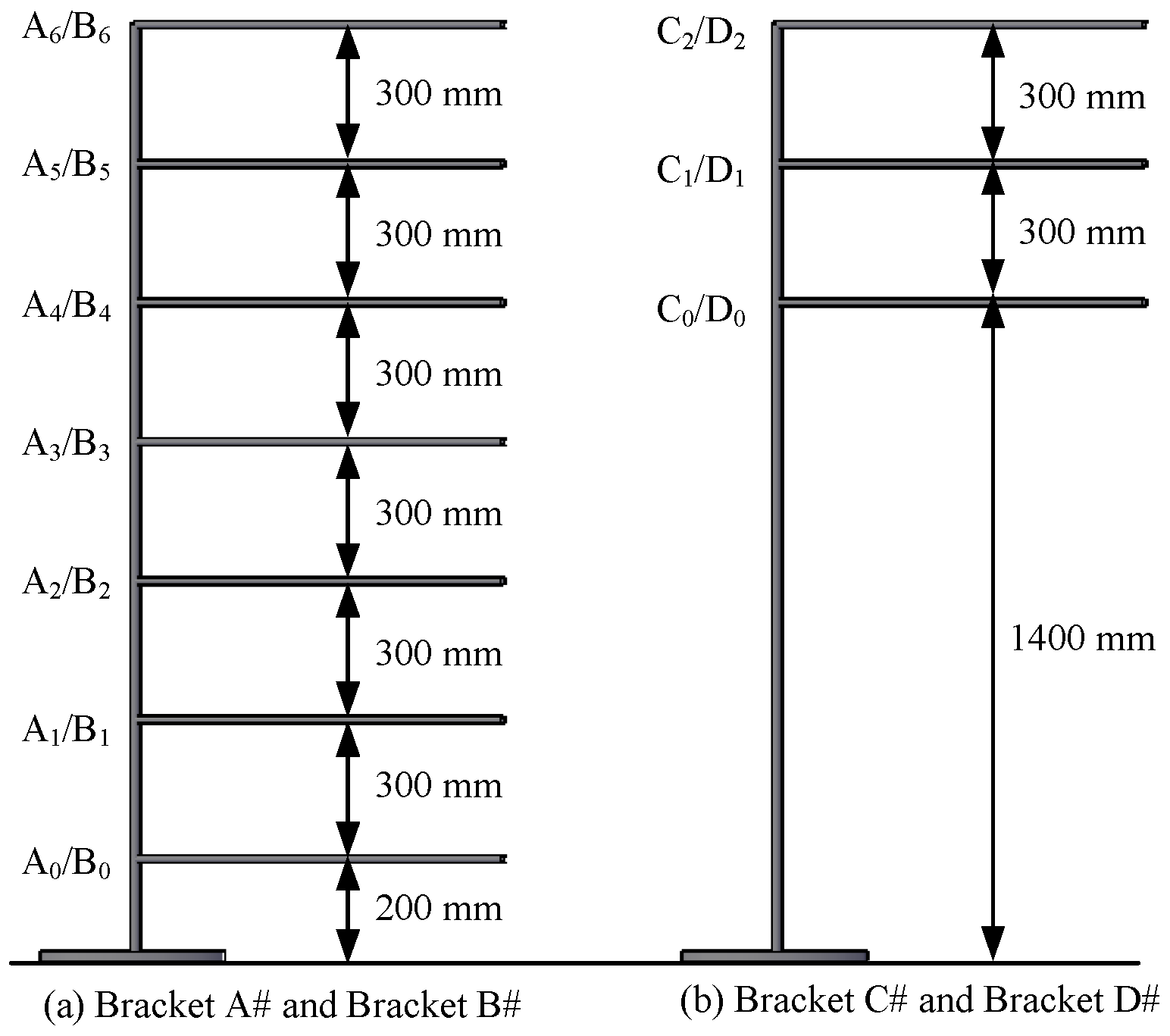
Figure 8.
Part flame images during the firefighting process for test 5.
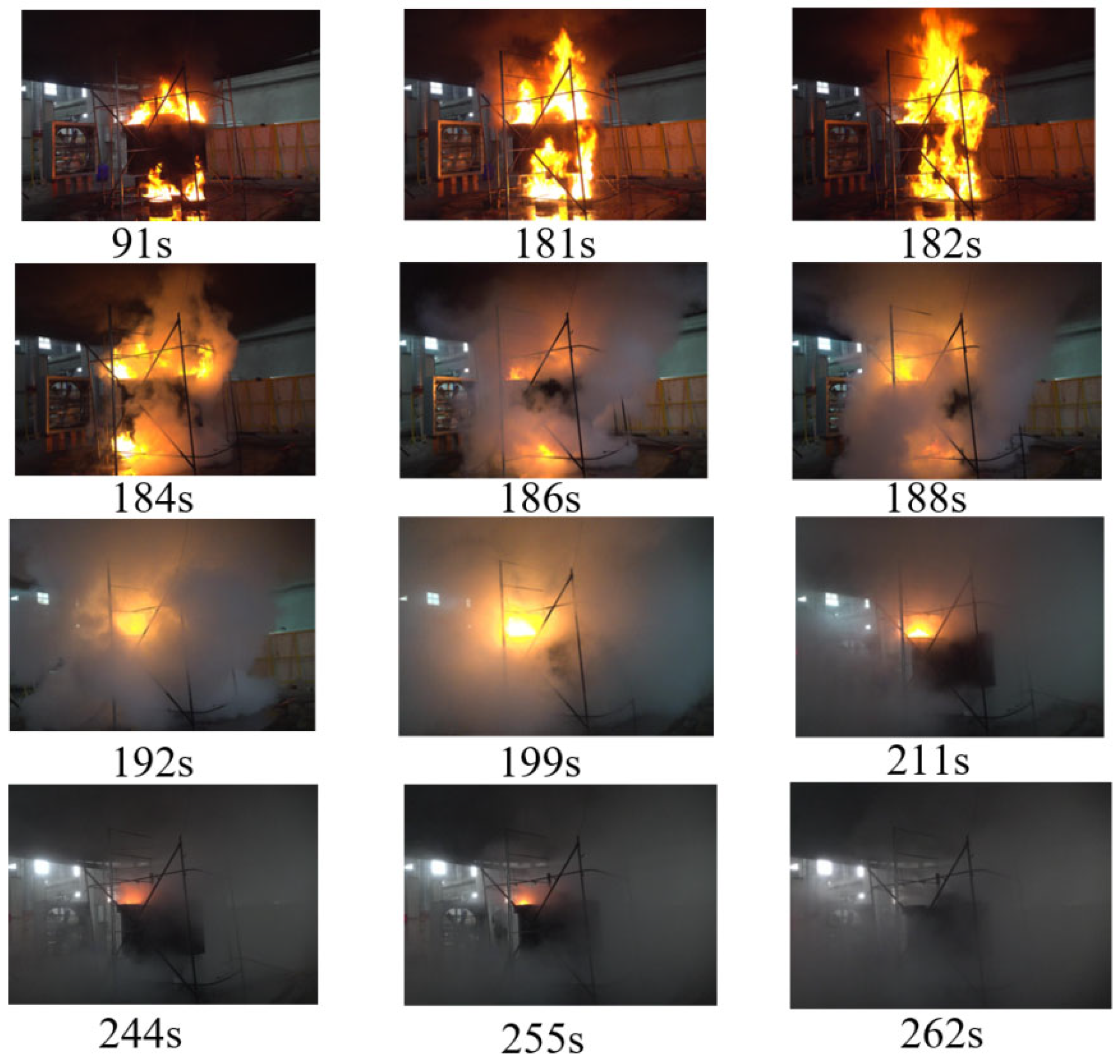
Figure 9.
Temporal evolution of temperature surrounding the transformer for test 5. (a) Bracket A#; (b) Bracket B#; (c) Bracket C#; (d) Bracket D#.
Figure 9.
Temporal evolution of temperature surrounding the transformer for test 5. (a) Bracket A#; (b) Bracket B#; (c) Bracket C#; (d) Bracket D#.

Figure 10.
Experiment results for tests 1#, 2#, 3#, 5#, 9#, 10# and 11#. (a) Temperature curves (measured point D0); (b) extinguishing times.
Figure 10.
Experiment results for tests 1#, 2#, 3#, 5#, 9#, 10# and 11#. (a) Temperature curves (measured point D0); (b) extinguishing times.

Figure 11.
Experiment results for tests 2#, 4# and 5#. (a) Temperature curves (measured point D0); (b) extinguishing times.
Figure 11.
Experiment results for tests 2#, 4# and 5#. (a) Temperature curves (measured point D0); (b) extinguishing times.
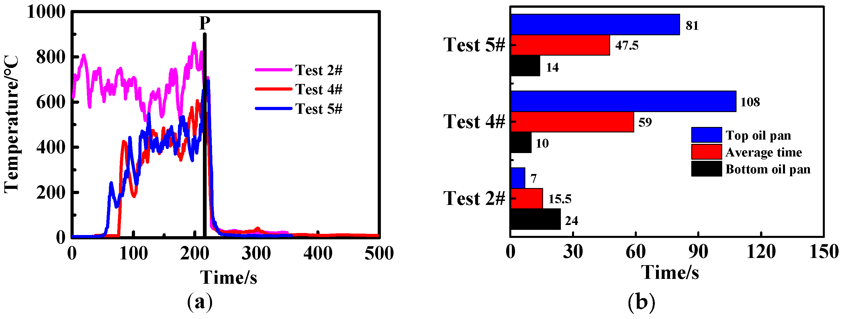
Figure 12.
Experiment results for tests 5#, 6#, 7# and 8#. (a) Temperature curves (measured point D0); (b) extinguishing times.
Figure 12.
Experiment results for tests 5#, 6#, 7# and 8#. (a) Temperature curves (measured point D0); (b) extinguishing times.


Table 1.
Similarity relationship between the prototype and the model.
| Items | Similar Relation | Proportional Coefficient | Prototype | Model |
|---|---|---|---|---|
| Boundary geometry of the transformer (mm) | lm/lf = C | 4 | 4000 | 1000 |
| Water flow rate of a single nozzle (L/min) | Qm/Qf = C5/2 | 32 | 10 | 0.3125 |
| Horizontal spacing between nozzles (mm) | dm/df = C | 4 | 2500 | 625 |
| Vertical interval between layers (mm) | hm/hf = C | 4 | 4000 | 1000 |
| Distance from the nozzle to the transformer (mm) | Lm/Lf = C1/2 | 2 | 1500 | 750 |
| Height from the top nozzle to the ground (mm) | Hm/Hf = C | 4 | 6800 | 1700 |
Note: the subscript m represents the prototype; the subscript f represents the model; C is the geometric proportionality coefficient. The physical meaning of the other letters is shown in Figure 3.
Table 2.
The results of the system design.
| System Pressure (MPa) | K Factor (L/min/MPa0.5) | Flow Rate of a Nozzle (L/min) | Number of Nozzles | Water Spray Intensity (L/min·m2) |
|---|---|---|---|---|
| 15 | 0.03 | 0.367 | 24 | 1.746 |
| 15 | 0.06 | 0.735 | 24 | 3.492 |
| 15 | 0.03 | 0.367 | 16 | 1.164 |
| 15 | 0.06 | 0.735 | 16 | 2.328 |
Table 3.
Basic parameters of the test.
| Density (kg/m3) | Kinematic Viscosity (mm2/s) | Point of Flammability (°C) | Gasoline (mL) | Transformer oil (mL) | Water (mL) |
|---|---|---|---|---|---|
| 882.8 | 9.4 | 155.5 | 5 | 500 | 4000 |
Table 4.
Test scheme.
| No. | Upper Nozzle Height (mm) | Air Speed (m/s) | K Factor (L/min/MPa0.5) | Total Nozzles Number | Oil Pans 5#–8# (s) | Oil Pans 1#–4# (s) | Average Extinguishing Time (s) |
|---|---|---|---|---|---|---|---|
| 1 | 1800 | 0 | 0.03 | 24 | 152 | 204 | 178 |
| 2 | 1800 | 0 | 0.06 | 24 | 24 | 7 | 15.5 |
| 3 | 1800 | 0 | 0.06 | 16 | 72 | 104 | 88 |
| 4 | 1600 | 0 | 0.06 | 24 | 10 | 108 | 59 |
| 5 | 1400 | 0 | 0.06 | 24 | 14 | 81 | 47.5 |
| 6 | 1400 | 0.5 | 0.06 | 24 | 55 | 79 | 67 |
| 7 | 1400 | 1 | 0.06 | 24 | 50 | 106 | 78 |
| 8 | 1400 | 2 | 0.06 | 24 | 89 | 76 | 82.5 |
| 9 | 1400 | 0 | 0.06 | 16 | 33 | 165 | 99 |
| 10 | 1400 | 0 | 0.03 | 16 | 62 | 249 | 155.5 |
| 11 | 1400 | 0 | 0.03 | 24 | 38 | 68 | 53 |
Disclaimer/Publisher’s Note: The statements, opinions and data contained in all publications are solely those of the individual author(s) and contributor(s) and not of MDPI and/or the editor(s). MDPI and/or the editor(s) disclaim responsibility for any injury to people or property resulting from any ideas, methods, instructions or products referred to in the content. |
© 2023 by the authors. Licensee MDPI, Basel, Switzerland. This article is an open access article distributed under the terms and conditions of the Creative Commons Attribution (CC BY) license (https://creativecommons.org/licenses/by/4.0/).
Share and Cite
MDPI and ACS Style
Song, H.; Yao, H.; Wei, X.; Qin, H.; Li, Y.; Lv, K.; Chen, Q. Experimental Study on Fire Suppression of the Outdoor Oil-Immersed Transformer by High-Pressure Water Mist System. Fire 2023, 6, 238. https://doi.org/10.3390/fire6060238
AMA Style
Song H, Yao H, Wei X, Qin H, Li Y, Lv K, Chen Q. Experimental Study on Fire Suppression of the Outdoor Oil-Immersed Transformer by High-Pressure Water Mist System. Fire. 2023; 6(6):238. https://doi.org/10.3390/fire6060238
Chicago/Turabian StyleSong, Huaitao, Haowei Yao, Xiaoge Wei, Hengjie Qin, Youxin Li, Kefeng Lv, and Qianlong Chen. 2023. "Experimental Study on Fire Suppression of the Outdoor Oil-Immersed Transformer by High-Pressure Water Mist System" Fire 6, no. 6: 238. https://doi.org/10.3390/fire6060238