Abstract
For adjacent coal seams, the downward invasion of harmful gases from an overlying coal mine goaf to the lower mining face could occur, and a high-level drainage tunnel is usually adopted for disaster prevention. Due to the high cost, instead of a high-level drainage tunnel, the high-level directional boreholes are widely adopted. In this study, the effect of a high-level drainage tunnel to prevent the downward invasion of carbon dioxide from the overlying coal mine goaf is analysed by applying a flow model in the numerical simulation. Then, the high-level directional boreholes are analysed to investigate the possibility of taking the place of the high-level drainage tunnel. The research results show that (1) for close adjacent coal seams, the downward invasion range of harmful carbon dioxide from the overlying coal mine goaf reaches one-third of the mining face, around 60 m wide; (2) a high-level drainage tunnel can effectively prevent the downward invasion of carbon dioxide from the overlying coal mine goaf by reducing carbon dioxide concentration within 0.3%; (3) the nine high-level directional boreholes with a careful layout can reduce the downward invasion of carbon dioxide from the overlying coal mine goaf to keep carbon dioxide concentration below 0.8% at the mining area, ensuring the coal mining safety.
1. Introduction
Coal is a major fuel for societal development in China, and underground coal mining contributes a large proportion of coal production. To ensure the high demand for coal consumption in China, it is necessary to ensure the safety of underground coal mining. The large emission of harmful gases is one of the main disaster types for underground coal mining, which is especially true for the adjacent coal seam group [1,2]. The harmful gases in the old coal mine goaves of an overlying coal seam can migrate into the lower mining face because of the developed fractures distributed in the rocks between these two coal seams [3,4].
Coal mine goaf is a porous space that is filled by the collapsed overlying rock mass and some residual coal. In the coal mine goaf, the residual coal may cause disaster under the fractures formed by the collapsed rock mass [5,6,7,8]. Due to the fractures formed by the collapsed rock mass in a coal mine goaf, air leakage in the mining face is inevitable under the negative-pressure ventilation system. In the air leakage phenomenon, some air flows from the mining face into a coal mine goaf and flows through the residual coal. The spontaneous heating process may take place among this residual coal, and this could develop into a spontaneous coal combustion disaster in a coal mine goaf [9,10,11,12]. Meantime, due to the stress–relief effect, the methane stored in the residual coal and coal pillars will desorb quickly and continually. As a result, the methane accumulates to increase its concentration in a coal mine goaf [13,14,15]. The increasing methane concentration poses a threat of the potential methane explosion as the friction between the collapsed rock mass can ignite this methane [16,17]. Besides, owing to the negative-pressure ventilation system, the desorbed methane in a coal mine goaf can flow back to the air-return roadway via from the upper corner of a mining face. However, the airflow at the upper corner of a mining face usually slows down, which causes increasing methane concentration that may exceed the limits [18,19]. Sometimes, in the air-return roadway, the ventilation volume is not enough to dilute the desorbed methane, resulting in the potential risk because of the increasing methane concentration [20,21].
For the adjacent coal seams, the downward invasion of the harmful gases from the old overlying coal mine goaf to the lower mining face occurs frequently [22,23,24]. When a coal mine goaf is formed, the overlying strata can be divided into three zones: the caved zone, fracture zone and bending zone [25,26,27]. In the caved zone, the porosity is high because of the developed fractures caused by the collapsed and crushed rock mass [28]. The volume of the crushed rock mass is bigger than the integrated rock mass because of the void space among the crushed rock mass. Under the support of the collapsed and crushed rock mass in the caved zone, the rock mass above the caved zone deformed with a few fractures. This formed the fracture zone with the broken rock mass [29]. The rock stratum above the fracture zone usually bends with little fractures, forming the bending zone [30]. If the overlying coal seam is in either the caved zone or the fracture zone, the harmful gases will flow downward to the mining face and air-return roadway in the lower coal seam, threatening coal mining of the lower mining face [31,32]. To ensure the safety of coal mining in the lower coal seam, a high-level drainage tunnel is usually adopted to prevent the downward invasion of harmful gases, such as methane, from the overlying coal seams and coal mine goaves [33,34,35,36]. Generally, the high-level drainage tunnel is excavated at the bottom of the fracture zone to drain methane with a higher concentration before it reaches the lower mining face [37,38]. At the bottom of the fracture zone, the broken rock mass and developed fracture provide enough channels for methane migration. Meantime, it avoids the developed airflow at the top of the caved zone where methane concentration is low due to the dilution of air leakage in coal mine goaf. Under this condition, the high-level drainage tunnel can drain the methane of higher concentration without the influence of the airflow in the caved zone. However, a high-level drainage tunnel is time-consuming and uneconomic. In recent years, high-level directional boreholes have been applied to try to take the place of the high-level drainage tunnel [39,40].
Due to the small borehole diameter, the drainage volume of the high-level directional boreholes is smaller than the high-level drainage tunnel [41,42]. However, the high-level directional boreholes usually could cover a larger area as they consist of a set of boreholes that are distributed separably [43]. The prevention effect of the high-level directional boreholes on the downward invasion of harmful gas from the overlying coal seams needs to be studied for successful and better application. However, most research focuses on the disaster prevention effect of either the high-level drainage tunnel or the high-level directional boreholes. The comparison of the prevention effect between these two drainage measures is seldom studied.
In this study, based on the engineering condition of the close adjacent two coal seams in the Jinhuagong coal mine, a gas flow model is used to simulate and verify the prevention effect of a high-level drainage tunnel and a set of high-level directional boreholes on the downward invasion of carbon dioxide from the close overlying old coal mine goaf. After the verification, a different layout of high-level directional boreholes is used in the numerical simulation for a better application solution.
2. Case Study Area
Jinhuagong coal mine is located in the northern part of Datong coal field, Datong, Shanxi, China. The longwall mining method is adopted in the Jinhuagong coal mine. The current mining face 8714 is the first mining face at coal seam #12-2, which is located in the eastern area of panel 307. The length of this mining face in the dip direction is 196 m, and the mining length in the strip direction is 1560 m. There are 116 hydraulic supports in the mining face, and these hydraulic supports are numbered from the air-inlet side to the air-return side. Above coal seam #12-2, there is an adjacent coal seam #11, which was mined out. The average distance between coal seam #12-2 and coal seam #11 is 20 m, as shown in Figure 1.
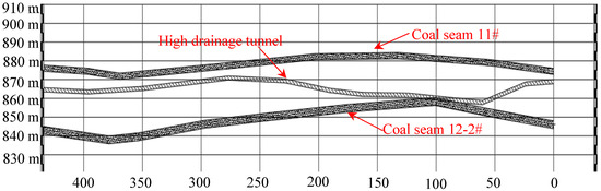
Figure 1.
Cross-section drawn of coal seam #12-2 and coal seam #11.
For mining face 8714 of coal seam #12-2, the average mining height is 4.5 m. The air-return roadway is entry 5714, while the air-inlet roadway is entry 2714. The layout of mining face 8714 is shown in Figure 2. The ventilation volume at mining face 8714 is 1879 m3/min. Based on the on-site measurement of the ventilation velocity, the ventilation volume in the air-inlet roadway of mining face 8714 is 2300 m3/min, while the ventilation volume in the air-return roadway of mining face 8714 is 2030 m3/min. During the mining period of mining face 8714, the gas monitoring results show that the lowest oxygen concentration at the mining face is around 18%. Under this working environment, the mining workers often felt exhausted, with tachycardia and perspiration.
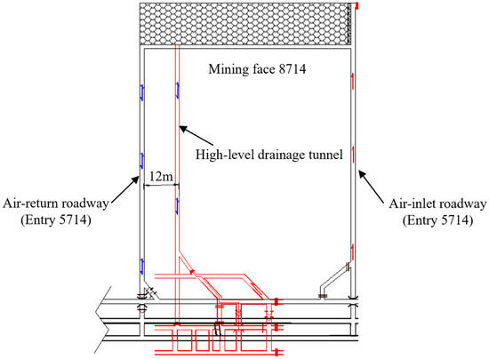
Figure 2.
Layout of mining face 8714.
To capture the distribution of oxygen concentration along the mining face 8714, 10 locations along the mining face 8714 are selected to collect air samples for test. The test results show that the oxygen concentration begins to decrease sharply at the middle location of the mining face. The minimum oxygen concentration is 18.05% at the 90th hydraulic support. Another low oxygen concentration is 18.38% at the air-return corner. Meantime, the carbon dioxide concentration along the mining face shows the opposite change. The carbon dioxide concentrations at the ninetieth hydraulic support and air-return corner are 1.92% and 1.68%, respectively. According to the test results for the gas collected from the overlying coal mine goaf, the carbon dioxide concentration is around 10%, while the ethane concentration varies between 0.001% and 0.1%. Ethane is a signal gas for spontaneous coal combustion. It is considered that there is residual coal oxidation in the large area in the overlying coal mine goaf. The test results for the collected air samples from mining face 8714 are shown in Table 1. In winter and early spring, the downward invasion of the carbon dioxide from the overlying coal mine goaf disappears. According to the Coal Mine Safety Regulations, carbon dioxide in the mining area, such as air-return roadway, should be below 1.5% to ensure coal mining safety. The downward invasion range of carbon dioxide from the overlying coal mine goaf is around 60 m wide.

Table 1.
Gas concentration along mining face 8714.
Although the test results for coal seam #12-2 show that it is easy to occur spontaneous combustion, the signature gases of spontaneous combustion for coal seam #12-2 are not detected. Since the distance between coal seam #11 and coal seam #12-2 is short, this could provide many fractures for carbon dioxide to invade mining face 8714 from the overlying coal mine goaf. Therefore, coal seam #11 is doubted to occur spontaneous coal combustion to produce carbon dioxide. Above the mining face 8714 of coal seam #12-2, the air samples in the coal mine goaf of coal seam #11 are collected. The test results show that in the coal mine goaf above mining face 8714 of coal seam #12-2, the average carbon dioxide concentration is around 10%. The test results for the collected air samples from coal seam #11 are shown in Table 2.
Table 2.
Gas concentration in coal mine goaf of coal seam #11.
To keep the air quality in the mining face 8714 of coal seam #12-2, a high-level drainage tunnel is excavated at the average height of 12 m above the mining face 8714. For this high-level drainage tunnel, its width is 3.2 m and its height is 2.2 m. The horizontal distance to the air-return roadway 5714 is 12 m. The drainage volume of this high-level drainage tunnel is around 400 m3/min, and the carbon dioxide concentration in the drainage airflow is between 1.5% and 2%. Under the effect of this high-level drainage tunnel, the carbon dioxide concentration at the corner of the air-return roadway is between 0.24% and 0.33%, while the carbon dioxide concentration in the air-return roadway is between 0.18% and 0.23%.
To reduce the cost of a high-level drainage tunnel, a set of high-level directional boreholes are tried and tested at the mining face 8714 of the Jinhuagong coal mine. In this set of high-level directional boreholes, there are six holes that are 7 m, 8 m, 9 m, 10 m, 15 m and 20 m away from the roof of mining face 8714, respectively. In the horizontal direction, these six holes are 3.5 m, 8.5 m, 18.6 m, 23.6 m, 28.6 m and 33.6 m away from the air-return roadway. The layout of these six high-level directional boreholes and the high-level drainage tunnel is shown in Figure 3. However, under the effect of these six high-level directional boreholes, the field measurement results show that the carbon dioxide concentration is around 2% at the upper corner of the mining face 8714 while it is around 1.5% in the air-return airflow, which threatens the safety of mining face 8714.
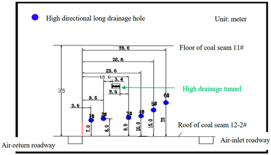
Figure 3.
Layout of high-level directional boreholes and the high-level drainage tunnel.
3. Numerical Simulation Methods
To study the reasonable layout of the high-level directional boreholes, the migration of carbon dioxide in coal mine goaf of mining face 8714 is studied. A gas flow model, shown in Figure 4, consisting of the controlling equations and coupling equations, is constructed to simulate the effect of gas drainage for the coal mine goaf of mining face 8714. In the controlling equations, the mass conversation equation and momentum conservation equation are used to describe the movement of mixture air in the coal mine goaf. The COMSOL (version 5.2a) software was used to realise the numerical simulation. As there are no temperature changes in this study, energy conservation is not included in this gas flow model. The gas is treated as the ideal gas, and the volume force is considered. As the effect of negative ventilation and high-level drainage tunnel on the airflow movement in the coal mine goaf, the flow state of the airflow changes among the laminar flow, turbulent flow and the transition flow. Therefore, the Forchheimer coefficient is considered in this gas flow because it can reflect the influence of inertial force which is vital for the airflow in the coal mine goaf. In the coupling equations, the species transport equation, porosity distribution equation and permeability distribution equations are used to describe the specific engineering environment in the coal mine goaf [44,45]. As the negative ventilation and negative drainage force the gas to flow in the porous goaf, the mechanical dispersion in the porous medium is considered with the molecular diffusion in the species transport equation. As it is difficult to determine the porosity distribution in a coal mine goaf, it is considered that the porosity change is continuous and slow, which is described in the coupling equations.
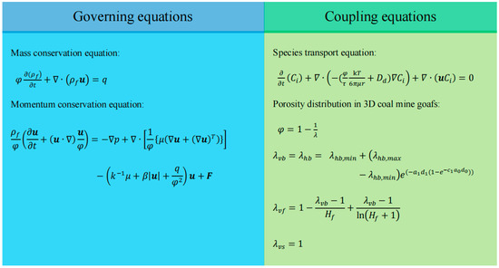
Figure 4.
Gas flow model coupling thermal buoyancy effect.
In this study, a geometry model was built based on the engineering condition of mining face 8714 of coal seam #12-2. This model consists of the air-inlet roadway, mining face 8714, air-return roadway, coal mine goaf of mining face 8714, and overlying coal mine goaf in coal seam #11. Besides, on the air-return side, the high-level drainage tunnel is constructed above the air-return roadway to obtain the migration of carbon dioxide in the coal mine goaf of mining face 8714. The initial conditions and boundary conditions are shown in Table 3 and Table 4. The high-level directional boreholes are constructed in this model to investigate its reasonable layout. The geometry models that are used in the numerical simulation are shown in Figure 5.
Table 3.
Setups of the numerical simulation.
Table 4.
Constant parameters in numerical gas flow model.
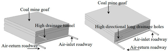
Figure 5.
Geometry model in numerical simulation for coal mine goaf.
4. Results and Discussion
4.1. Validation of Carbon Dioxide Migration in Coal Mine Goaf
The distribution of carbon dioxide concentration in the coal mine goaf under the drainage effect of a high-level drainage tunnel is shown in Figure 6. The red arrow shows the airflow direction and it is clear that carbon dioxide in the overlying old coal mine goaf flows into the high-level drainage tunnel and the lower mining face. The concentration of carbon dioxide in the overlying coal mine goaf is around 10%. Under the effect of the negative-pressure ventilation in the lower mining face and the developed fractures among the caved rock mass in coal mine goaves, carbon dioxide shows an obvious downward movement. The concentration of carbon dioxide gradually decreases from around 10% in the overlying coal mine goaf to around 1% in the lower coal mine goaf. During the downward movement of carbon dioxide, the high-level drainage tunnel sucks much carbon dioxide for its negative drainage effect. This prevents much carbon dioxide from flowing downward, though some escapes into the lower coal mine goaf. When carbon dioxide flows into the mining face and upper corner of the mining face from the coal mine goaf, the fresh airflow further decreases its concentration by dilution effect. The carbon dioxide concentration is around 0.2% at the upper corner of the lower mining face. Under the drainage effect of the high-level drainage tunnel, some carbon dioxide is sucked into this tunnel and cannot migrate to the lower mining face. When the airflow is stable in this high-level drainage tunnel, the carbon dioxide concentration is around 1.8%.
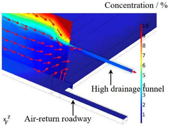
Figure 6.
Distribution of carbon dioxide in the coal mine goaf under the effect of a high-level drainage tunnel.
The concentration distribution of carbon dioxide at the representative location is shown in Figure 7. According to Figure 7, the concentration of carbon dioxide in the high-level drainage tunnel is around 7.5% when the high-level drainage tunnel starts to work. The final stable concentration of carbon dioxide in the high-level drainage tunnel is around 1.8% after eight hours, which is consistent with the on-site measurement. The concentration of carbon dioxide along the mining face is shown in Figure 8. It can be seen that, in the mining face, the carbon dioxide concentration is between 0.02–0.03% at the location that is around 40 m away from the air-inlet roadway side. When the location moves to around 70 m away from the air-inlet roadway side, the carbon dioxide concentration is between 0.04–0.09%. It can be obtained that, from the air-inlet side to the air-return side, the carbon dioxide concentration remains at a low level before it approaches the middle of the mining face. Thereafter, the carbon dioxide concentration increases quickly to 0.2% at the upper corner of the mining face. After comparison, it can be seen that the numerical simulation result is basically consistent with the on-site measured result of the lower mining face 8714.
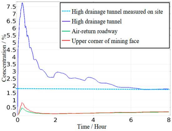
Figure 7.
Change of carbon dioxide at the representative locations of mining face 8714.
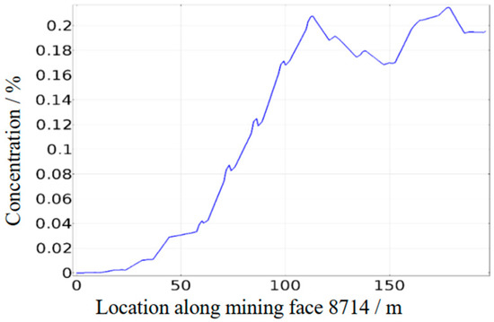
Figure 8.
Change of carbon dioxide along mining face 8714.
The record for the concentration of carbon dioxide at the upper corner of the mining face and on the air-return side is shown in Table 5. According to the on situ data, under the conditions of a high-level drainage tunnel, the carbon dioxide concentration in the mining face increases from around 0.02% on the air-inlet side to around 0.19% on the air-return side.
Table 5.
Carbon dioxide concentration was measured at the representative locations.
For the effect of the high-level directional boreholes on the migration of carbon dioxide in coal mine goaves, the numerical simulation results of carbon dioxide concentration distribution in the coal mine goaf are shown in Figure 9. In the dip direction, carbon dioxide mainly accumulates on the air-return side in a coal mine goaf. On the plane that is one meter above the coal seam roof, under the drainage effect of the high-level directional boreholes, the maximum concentration of carbon dioxide is around 3.5% at the air-return corner in the coal mine goaf, while it is around 9% on the plane that is 24 m above the coal seam roof. In the strike direction, carbon dioxide concentration decreases quickly when it departs the area close to the mining face. After the comparison of these two figures in Figure 9, it is obvious that the carbon dioxide mainly flows to the air-return side of the coal mine goaf. Under the drainage effect of the high-level directional boreholes, some carbon dioxide is drained away from the coal mine goaf. The higher concentration area of carbon dioxide gradually decreases when it is close to the lower mining face from the overlying coal mine goaf. Meantime, the maximum concentration of carbon dioxide decreases from around 9% to 3.5%.
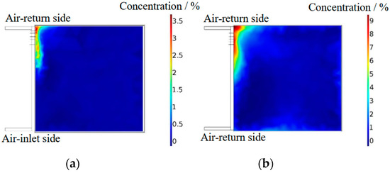
Figure 9.
Distribution of carbon dioxide concentration in a coal mine goaf under the effect of high-level directional boreholes. (a) Section one meter above the coal seam roof; (b) section 24 meters above the coal seam roof.
The changes in carbon dioxide concentration in the high-level directional boreholes, air-return roadway and the upper corner of mining face 8714 are shown in Figure 10. Under the effect of the high-level directional boreholes, the concentration of carbon dioxide in the air-return roadway and upper corner of the mining face gradually increases to a stable level. The concentration of carbon dioxide in the air-return roadway approximates 1.4% with a small increase rate, while it is around 2% with a small increase rate at the upper corner of mining face 8714. The concentration of carbon dioxide in the drainage holes varies between 2.2% to 2.6%, and the average concentration of carbon dioxide is around 2.4%. The concentration of carbon dioxide measured on-site is listed in Table 6. The concentration of carbon dioxide at the upper corner of the mining face is between 1.5% to 2.3%, and it is between 1.2% to 1.8% in the air-return roadway, while it is between 1.4% and 2.6% in the outflow of the extraction pumps. After the comparison between the numerical simulation results and on-site measured results in Table 6, it can be obtained that, at the stable stage, the numerical simulation result is basically consistent with the on-site measured results.
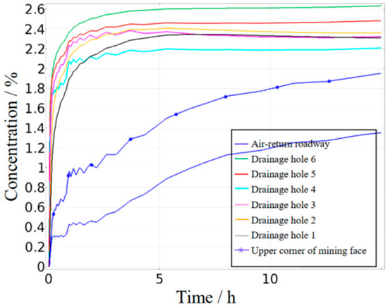
Figure 10.
Change of carbon dioxide at the monitoring points under the effect of high-level directional boreholes.
Table 6.
Carbon dioxide concentration was measured at the representative monitoring points.
Under the effect of the high-level directional boreholes, the concentration change of carbon dioxide along the mining face is shown in Figure 11. From the air-inlet side to the air-return side of mining face 8714, carbon dioxide concentration is below 0.5% before the middle of the mining face. Then, it increases quickly to around 2% at the air-return side, causing oxygen-poor air quality in the second half of the mining face. According to Figure 11, the numerical simulation is consistent with the on-site measurement results.
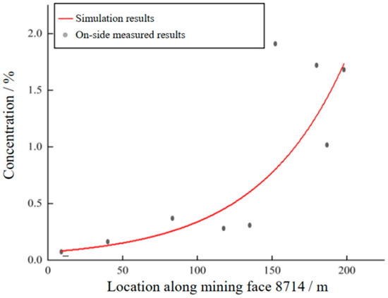
Figure 11.
Change of carbon dioxide along the mining face under the effect of high-level directional boreholes.
According to the above prevention effect of high-level drainage tunnel and high-level directional boreholes, the wide range of downward invasion of carbon dioxide was formed because of the short distance between coal seam #12-2 and its overlying coal seam. The current layout of the high-level directional boreholes is not appropriate to prevent carbon dioxide from flowing into the upper corner of the mining face. The number and the layout of the high-level directional boreholes are considered to be the main reasons for this situation. Therefore, it is necessary to study the effect of the layout and number of high-level directional boreholes on the prevention of the downward invasion of carbon dioxide from the old coal mine goaf of the overlying coal seam.
4.2. Optimisation of Prevention Effect of High-Level Directional Boreholes on Downward Invasion of Carbon Dioxide
After the numerical simulations on the disaster prevention effect of different layouts of the six high-level directional boreholes, it is concluded that six high-level directional boreholes are enough to prevent the downward invasion of harmful carbon dioxide for the adjacent coal seams. The numerical simulation results show that nine high-level directional boreholes with a special layout can ensure that the carbon dioxide concentration is below the limits in the air-return roadway and the upper corner of the mining face. For these nine high-level directional boreholes, five drainage holes are set to be 19 m high above the coal seam roof, while the other four drainage holes are set to be 10 m high above the coal seam roof. The geometry model in the numerical simulation is shown in Figure 12. The change of carbon dioxide concentration in the nine high-level directional boreholes, air-return roadway and upper corner of the 8714 mining face is shown in Figure 13.
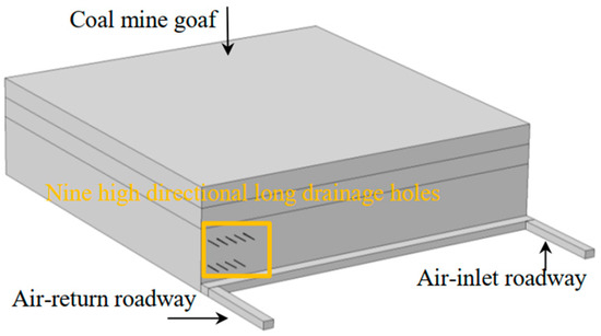
Figure 12.
Geometry model for the numerical simulation of nine high-level directional boreholes.
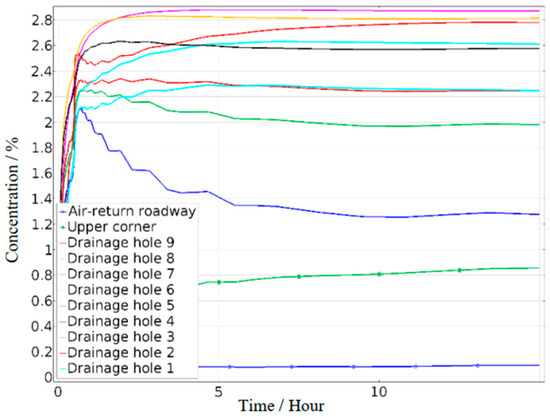
Figure 13.
Change of carbon dioxide at the monitoring points under the effect of nine high-level directional boreholes.
According to the numerical simulation results, it can be seen that the drainage effect of the nine high-level directional boreholes is not significant when these high-level directional boreholes start. At the initial drainage stage, the carbon dioxide concentration in the upper corner of the mining face and the air-return roadway rapidly increases. The carbon dioxide concentration is around 0.4% at the upper corner of mining face 8714, and the carbon dioxide concentration is around 1.3% in the air-return roadway. As the gas drainage progresses for five hours, the gas drainage effect of high-level directional boreholes gradually stabilises with the stable carbon dioxide concentration in the high-level directional boreholes. At this stable stage, the carbon dioxide concentration in the upper corner of the mining face and the air-return roadway decreases to a steady level. At the upper corner of mining face 8714, the carbon dioxide concentration is around 0.8%. In the air-return roadway, the carbon dioxide concentration stays around 0.1%. In the mining face, the carbon dioxide concentration is close to 0% in the first 120 m area from the air-inlet roadway side. Outside this low-concentration region, the carbon dioxide concentration in the mining face begins to increase as the location approaches the air-return roadway side. At the upper corner of mining face 8714, the carbon dioxide concentration is stable at 0.8%.
Compared with the drainage effect of the six high-level directional boreholes, under this condition of nine high-level directional boreholes, the carbon dioxide concentration in the mining face, the upper corner of the mining face, and the air-return roadway significantly decreases and meets the safety production requirements. The carbon dioxide concentration at the upper corner decreased from the range of 1.4–2.5% to 0.8%. The carbon dioxide concentration in the air-return roadway decreased from the range of 0.1–0.6% to 0.1%. Nine high-level directional boreholes with this two-row layout can effectively improve the gas drainage effect to ensure the safety of the mining face.
5. Conclusions
- (1)
- For close adjacent coal seams, the downward invasion region of the harmful carbon dioxide from the overlying coal mine goaf is wide. In the Jinhuagong coal mine, the average distance between the lower coal seam #12-2 and the overlying coal seam #11 is 20 m. Due to the small distance between these two coal seams and the negative ventilation system, the downward invasion of carbon dioxide from the overlying coal mine goaf could lead to the quick decrease of oxygen concentration in the last 60 m of the mining face. The maximum concentration of carbon dioxide reaches 1.68% at the air-return corner of the mining face of the lower coal seam.
- (2)
- The high-level drainage tunnel can effectively prevent the downward invasion of carbon dioxide from the overlying coal mine goaf to the lower mining face. For mining face 8714 in Jinhuagong coal mine, a high-level drainage tunnel, 12 m above the mining face and 12 m away from the air-return roadway can effectively prevent the downward invasion of carbon dioxide from the overlying coal mine goaf with the steady drainage concentration of 1.8% to ensure the mining safety by reducing the carbon dioxide concentration within 1.5%. In contrast, the six high-level directional boreholes cannot reduce carbon dioxide concentration below the limits in the mining face and air-return roadways.
- (3)
- With an optimised layout, the nine high-level directional boreholes can take the place of a high-level drainage tunnel to prevent the downward invasion of carbon dioxide from the overlying coal mine goaf. For the six high-level directional boreholes applied in mining face 8714, carbon dioxide in the air-return airflow and at the upper corner of the mining face can exceed 1.5% to endanger coal mining. With the two-row layout of nine high-level directional boreholes, carbon dioxide at the upper corner of the mining face is around 0.8%, and it is around 0.1% in the air-return airflow, satisfying the requirement of coal mining safety.
Author Contributions
Conceptualization, L.L. and X.C. (Xiangjun Chen); methodology, L.L., X.C. (Xiangjun Chen) and L.W.; software, L.L. and X.C. (Xinyi Chen); validation, L.L., X.C. (Xinyi Chen) and L.W.; formal analysis, L.L. and X.C. (Xinyi Chen); investigation, L.L. and X.C. (Xinyi Chen); resources, L.L. and X.C. (Xiangjun Chen); data curation, L.L., X.C. (Xinyi Chen) and L.W.; writing—original draft preparation, L.L. and X.C. (Xinyi Chen); writing—review and editing, L.L., X.C. (Xinyi Chen) and X.C. (Xiangjun Chen); visualization, L.L. and X.C. (Xinyi Chen); supervision, L.L. and X.C. (Xiangjun Chen); project administration, L.L. and X.C. (Xiangjun Chen); funding acquisition, L.L. and X.C. (Xiangjun Chen). All authors have read and agreed to the published version of the manuscript.
Funding
This study was supported by the Doctoral Foundation of Henan Polytechnic University (B2021-7), the State Key Laboratory Cultivation Base for Gas Geology and Gas Control (Henan Polytechnic University) (No. WS2021A06), the Postdoctoral Research Grant in Henan Province (No. 202102057), the National Natural Science Foundation of China (No. 52304213, No. 52074105, No. 52074108), the Program for Innovative Research Team of Henan Polytechnic University (No. T2019-4).
Institutional Review Board Statement
Not applicable.
Informed Consent Statement
Not applicable.
Data Availability Statement
Data are contained within the article.
Conflicts of Interest
The authors declare no conflict of interest.
Nomenclature
| Porosity | |
| Velocity vector (m/s) | |
| Fluid source/sink term (kg/(m3·s)) | |
| Pressure (Pa) | |
| Fluid viscosity (kg/(m·s)) | |
| Permeability (m2) | |
| Forchheimer coefficient | |
| Gas density (kg/m3) | |
| Volume force (N/m3) | |
| Adjustment coefficient | |
| Mechanical dispersion (cm2/s) | |
| Relative molecular mass of gas (g/mol) | |
| Concentration of species (mol/m3) | |
| Boltzman constant (J/K) | |
| Coal diameter (m) | |
| Bulking factor | |
| Height of fracture zone (m) | |
| / | Vertical/horizontal bulking factor in broken zone |
| / | Vertical bulking factor in fracture/sinking zone |
| Minimum/maximum of the horizontal bulking factor in broken zone | |
| Attenuation rate of the distance to the boundary/mining face | |
| Distance to the boundary/mining face (m) | |
| Fluid density (kg/m3) |
References
- Ma, L.; Guo, R.; Wu, W.; Wang, R.; Wei, G. Determination on the hazard zone of spontaneous coal combustion in the adjacent gob of different mining stages. Process Saf. Environ. Prot. 2020, 142, 370–379. [Google Scholar] [CrossRef]
- Xue, Y.; Gao, F.; Gao, Y.; Cheng, H.; Liu, Y.; Hou, P.; Teng, T. Quantitative evaluation of stress-relief and permeability-increasing effects of overlying coal seams for coal mine methane drainage in Wulan coal mine. Nat. Gas Sci. Eng. 2016, 32, 122–137. [Google Scholar] [CrossRef]
- Wu, X.; Lu, Y.; Gu, W.; Xing, S.; Li, J.; Guo, X.; Peng, J. Determination of coal spontaneous combustion zone in overlaying multilayer goaf and its control technology of thickened slurry. Combust. Sci. Technol. 2024, 1–23. [Google Scholar] [CrossRef]
- Qin, W.; Xu, J.; Hu, G. A method for estimating abandoned gob methane reserves based on the “Three-zone” theory of relieved gas delivery in coal seams. Energy Source Part A 2013, 35, 585–593. [Google Scholar] [CrossRef]
- Zheng, Y.; Li, Q.; Zhu, P.; Li, X.; Zhang, G.; Ma, X.; Zhao, Y. Study on multi-field evolution and influencing factors of coal spontaneous combustion in goaf. Combust. Sci. Technol. 2021, 195, 247–264. [Google Scholar] [CrossRef]
- Liu, Q.; Lin, B.; Zhou, Y.; Li, Y. Porosity model of the goaf based on overlying strata movement and deformation. Environ. Earth Sci. 2022, 81, 214. [Google Scholar] [CrossRef]
- Li, L.; Qin, B.T.; Liu, J.S.; Leong, Y.K. Integrated experimentation and modeling of the formation processes underlying coal combustion-triggered methane explosions in a mined-out area. Energy 2020, 203, 117855. [Google Scholar] [CrossRef]
- Li, L.; Qin, B.T.; Ma, D.; Zhuo, H.; Liang, H.; Gao, A. Unique spatial methane distribution caused by spontaneous coal combustion in coal mine goafs: An experimental study. Process Saf. Environ. 2018, 116, 199–207. [Google Scholar] [CrossRef]
- Li, L.; Qin, B.T.; Liu, J.; Leong, Y.; Li, W.; Zeng, J.; Ma, D.; Zhuo, H. Influence of airflow movement on methane migration in coal mine goafs with spontaneous coal combustion. Process Saf. Environ. 2021, 156, 405–416. [Google Scholar] [CrossRef]
- Hui, Z.; Qin, B.; Qin, Q. The impact of surface air leakage on coal spontaneous combustion hazardous zone in gob of shallow coal seams: A case study of Bulianta Mine, China. Fuel 2021, 295, 120636. [Google Scholar]
- Chan, Z.; Zhou, B.; Wang, J.; Lu, Z.; Yang, Q.; Dong, Z.; Dong, K. Long-distance migration law of radon in overburden of abandoned goaf during coal spontaneous combustion. J. Environ. Radioact. 2023, 270, 107284. [Google Scholar] [CrossRef]
- Lu, W.; Cao, Y.J.Z.; Tien, J.C. Method for prevention and control of spontaneous combustion of coal seam and its application in mining field. Int. J. Min. Sci. Technol. 2017, 27, 839–846. [Google Scholar] [CrossRef]
- Duda, A. The impact of atmospheric pressure changes on methane emission from goafs to coal mine workings. Energies 2023, 17, 173. [Google Scholar] [CrossRef]
- Wang, Y.; Fan, X.X.; Niu, K.; Shi, G. Estimation of hydrogen release and conversion in coal-bed methane from roof extraction in mine goaf. Int. J. Hydrogen Energy 2019, 44, 15997–16003. [Google Scholar] [CrossRef]
- Liu, S.; Shi, G.; Ren, H.; Wang, D. Effect of diurnal fluctuation of atmospheric pressure on gas migration in goaf of coal mine. Process Saf. Environ. 2023, 174, 310–319. [Google Scholar] [CrossRef]
- Ma, D.; Qin, B.T.; Li, L.; Gao, A.; Gao, Y. Study on the methane explosion regions induced by spontaneous combustion of coal in longwall gobs using a scaled-down experiment set-up. Fuel 2019, 254, 115547. [Google Scholar] [CrossRef]
- Qin, B.; Li, L.; Ma, D.; Lu, Y.; Zhong, X.; Jia, Y. Control technology for the avoidance of the simultaneous occurrence of a methane explosion and spontaneous coal combustion in a coal mine: A case study. Process Saf. Environ. 2016, 103, 203–211. [Google Scholar] [CrossRef]
- Jia, H.; Wang, Z.; Zhao, X.; Ma, S.; Song, Z.; Chen, J. Characterization of spatiotemporal distribution of gas in the goaf of W-type ventilated working face. Process Saf. Environ. 2024, 184, 1379–1388. [Google Scholar] [CrossRef]
- Wang, Z.; Ren, T.; Cheng, Y. Numerical investigations of methane flow characteristics on a longwall face Part II: Parametric studies. J. Nat. Gas Sci. Eng. 2017, 43, 254–267. [Google Scholar] [CrossRef]
- Wang, K.; Zhou, W.; Zhou, A.; Jiang, Y.F.; Feng, S. Experimental study of high concentrations of coal mine methane behavior in downward ventilated tilted roadways. J. Wind Eng. Ind. Aerodyn. 2016, 158, 69–80. [Google Scholar] [CrossRef]
- Toraño, J.; Torno, S.; Menéndez, M.; Gent, M.; Velasco, J. Models of methane behavior in auxiliary ventilation of underground coal mining. Int. J. Coal Geol. 2009, 80, 35–43. [Google Scholar] [CrossRef]
- Szlqzak, N.; Obracaj, D.; Swolkień, J. Methane drainage from roof strata using an overlying drainage gallery. Int. J. Coal Geol. 2014, 136, 99–115. [Google Scholar]
- Zhang, R.; Cheng, Y.; Zhou, H.; Yuan, L.; Li, W.; Liu, Q.; Jin, K.; Tu, Q. New insights into the permeability-increasing area of overlying coal seams disturbed by the mining of coal. J. Nat. Gas Sci. Eng. 2018, 49, 352–364. [Google Scholar] [CrossRef]
- Zhou, X.; Yang, Y.; Zheng, K.; Miao, G.; Wang, M.; Li, P. Study on the spontaneous combustion characteristics and prevention technology of coal seam in overlying close goaf. Combust. Sci. Technol. 2020, 194, 2233–2254. [Google Scholar] [CrossRef]
- Yuan, Y.; Yuan, H. Detecting the Gob Area of Coal Mines Based on 4D Seismic Interpretation; NASA: Washington, DC, USA, 2019. [Google Scholar]
- Qun, Z. Theoretical study on calculation limits of CBM resource of abandoned coal mine. Coal Geol. Explor. 2004, 32, 29–31. [Google Scholar]
- Guo, P.Y.; Zheng, L.G.; Sun, X.M.; He, M.; Wang, Y.; Shang, J. Sustainability evaluation model of geothermal resources in abandoned coal mine. Appl. Therm. Eng. 2018, 144, 804–811. [Google Scholar] [CrossRef]
- Li, Y.; Ren, Y.Q.; Peng, S.S.; Cheng, H.Z.; Wang, N.; Luo, J.B. Measurement of overburden failure zones in close-multiple coal seams mining. Int. J. Min. Sci. Technol. 2021, 31, 43–50. [Google Scholar] [CrossRef]
- Palchik, V. Formation of fractured zones in overburden due to longwall mining. Environ. Geol. 2003, 44, 28–38. [Google Scholar] [CrossRef]
- Zhang, C.; Yu, L.; Feng, R.; Zhang, Y.; Zhang, G. A Numerical study of stress distribution and fracture development above a protective coal seam in longwall mining. Processes 2018, 6, 146. [Google Scholar] [CrossRef]
- Wang, G.; Wu, M.; Wang, R.; Xu, H.; Song, X.J. Height of the mining-induced fractured zone above a coal face. Eng. Geol. 2017, 216, 140–152. [Google Scholar] [CrossRef]
- Zhao, Y.; Lin, B.; Liu, T.; Yang, W. Influence of hard-roof on gas accumulation in overlying strata: A case study. J. Nat. Gas Sci. Eng. 2021, 90, 103948. [Google Scholar] [CrossRef]
- Xu, C.; Wang, K.; Li, X.; Yuan, L.; Zhao, C.; Guo, H. Collaborative gas drainage technology of high and low level roadways in Highly-Gassy Coal Seam Mining. Fuel 2022, 323, 124325. [Google Scholar] [CrossRef]
- Xu, C.; Sun, H.; Wang, K.; Qin, L.; Guo, C.; Wen, Z. Effect of low-level roadway tunneling on gas drainage for underlying coal seam mining: Numerical analysis and field application. Greenh. Gases 2021, 11, 780–794. [Google Scholar] [CrossRef]
- Wang, Y.; Zhang, Y. Study on optimization of layout parameters of high-level boreholes in Pingdingshan coal mine. Sci. Rep. 2023, 13, 19759. [Google Scholar] [CrossRef]
- Li, H.; Liu, Y.; Wang, W.; Liu, M.; Ma, J.; Guo, X.; Guo, H. The integrated drainage technique of directional high-level borehole of super large diameter on roof replacing roof extraction roadway: A case study of the underground Zhaozhuang Coal Mine. Energy Rep. 2020, 6, 2651–2666. [Google Scholar] [CrossRef]
- Liu, J.; Wang, Z.; Wang, Q.; Zou, S.; Yang, X. Study on the application of comprehensive gas control technology for Source-Separated Three-Dimensional gas extraction in large mining faces. ACS Omega 2024, 9, 32777–32788. [Google Scholar] [CrossRef]
- Hu, G.; Xu, J.; Zhang, F.; Zhao, C.; Qin, W.; Yiran, Z. Coal and coalbed methane Co-Extraction technology based on the ground movement in the Yangquan coalfield; China. Energies 2015, 8, 6881–6897. [Google Scholar] [CrossRef]
- Li, T.; Wu, B.; Lei, B. Study on the optimization of a gas drainage borehole drainage horizon based on the evolution characteristics of mining fracture. Energies 2019, 12, 4499. [Google Scholar] [CrossRef]
- Gao, H.; Lei, Y. Research on gas control technology of “U+ Omni-Directional roof to Large-Diameter High-Level drilling hole” at the end mining face of multi-source goaf. Processes 2023, 11, 320. [Google Scholar] [CrossRef]
- Li, S.; Li, J.W.; Zheng, G.Y.; Ma, N.N. Numerical Simulation of Gas Transportation in Mechanized Top-Coal Caving with Gob-Side Entry Retaining. Appl. Mech. Mater. 2014, 577, 1170–1173. [Google Scholar] [CrossRef]
- Zhang, X.; Yang, M. Determination of Optimal Extrication Location of High Extraction Roadway of Large-Mining-Height Fully Mechanized Face. Adv. Civ. Eng. 2018, 2018, 5145746. [Google Scholar] [CrossRef]
- Yang, F.; Ge, Z.; Chen, J.; Cheng, L.; Lei, H.; Zou, L. A comprehensive gas extraction system coupling high-level suction roadway and boreholes for gas disaster prevention in closely-spaced multiple coal seams. Energy Sources Part A-Recovery Util. Environ. Eff. 2020, 1–14. [Google Scholar] [CrossRef]
- Yuan, L.M.; Smith, A.C. Numerical study on effects of coal properties on spontaneous heating in longwall gob areas. Fuel 2008, 87, 3409–3419. [Google Scholar] [CrossRef]
- Greuer, R. Study of Mine Fire Fighting Using Inert Gases; Final Contract Report; Michigan Technological University: Houghton, MI, USA, 1974. [Google Scholar]
Disclaimer/Publisher’s Note: The statements, opinions and data contained in all publications are solely those of the individual author(s) and contributor(s) and not of MDPI and/or the editor(s). MDPI and/or the editor(s) disclaim responsibility for any injury to people or property resulting from any ideas, methods, instructions or products referred to in the content. |
© 2024 by the authors. Licensee MDPI, Basel, Switzerland. This article is an open access article distributed under the terms and conditions of the Creative Commons Attribution (CC BY) license (https://creativecommons.org/licenses/by/4.0/).