Article

Advanced Numerical Analysis of In-Cylinder Combustion and NOx Formation Using Different Chamber Geometries

by
Arun Teja Doppalapudi
and
Abul Kalam Azad
*
School of Engineering and Technology, Central Queensland University, 120 Spencer Street, Melbourne, VIC 3000, Australia
*
Author to whom correspondence should be addressed.
Submission received: 14 December 2023 / Revised: 17 January 2024 / Accepted: 22 January 2024 / Published: 24 January 2024
(This article belongs to the Special Issue State-of-the-Art on Combustion and Flames)

Abstract

:
In diesel engines, emission formation inside the combustion chamber is a complex phenomenon. The combustion events inside the chamber occur in microseconds, affecting the overall engine performance and emissions characteristics. This study opted for using computational fluid dynamics (CFD) to investigate the combustion patterns and how these events affect nitrogen oxide (NOx) emissions. In this study, a diesel engine model with a flat combustion chamber (FCC) was developed for the simulation. The simulation result of the heat release rate (HRR) and cylinder pressure was validated with the experimental test data (the engine test was conducted at 1500 rpm at full load conditions). The validated model and its respective boundary conditions were used to investigate the effect of modified combustion chamber profiles on NOx emissions. Modified chambers, such as a bathtub combustion chamber (BTCC) and a shallow depth chamber (SCC), were developed, and their combustion events were analysed with respect to the FCC. This study revealed that combustion events such as fuel distribution, unburnt mass fractions, temperature and turbulent zones directly impact NOx emissions. The modified chambers controlled the spread of combustion and provided better fuel distribution, improving engine performance and combustion rates. The SCC (63.2 bar) showed peak pressure rates compared to the FCC (63.02 bar) and BTCC (62.72 bar). This study concluded that the SCC showed better results than other chambers. This study further recommends conducting lean fuel mixture combustion with chamber modifications and optimising fuel spray, such as by adjusting the fuel injection profile, spray angle and injection timing, which has a better tendency to create complete combustion.

1. Introduction

Nitrogen oxide (NOx) emissions are still a significant concern in diesel engines, which are directly influenced by many operational parameters [1,2]. In addition, these emissions create more alarming situations with renewable biodiesel fuel [3]. In general, NOx emissions form at higher temperatures where the atmospheric nitrogen reacts with the oxygen and causes higher NOx emissions [4]. NOx emissions form in different mechanisms, mainly thermal (as per the Zeldovich mechanism), prompt (Fenimore), the N2O pathway, fuel-bound nitrogen and the NNH mechanism [5]. NOx emissions mostly contain NO, nitrogen dioxide (NO2) and nitrous oxide (N2O). Thermal NO accounts for >90% of total NOx from diesel engines. NO is one of many harmful emissions released from burning fossil fuels. This pollutant causes many human health hazards and environmental problems similar to NO2 gas [6]. However, NO2, the other most common form of nitrogen oxides, contributes to acid rain, photochemical smog and particulate matter, causing adverse effects on humans and the environment, such as respiratory problems, tropospheric ozone and eutrophication [7,8,9].
Recent studies have proposed several advanced techniques to reduce NOx emissions, such as low-temperature combustion (LTC) strategies, fuel emulsion techniques, chamber modifications and exhaust gas after-treatment systems [10,11]. Though LTC can achieve near-zero NOx emissions, the major disadvantage of LTC strategies is combustion control [10]. In addition, water emulsion and fumigation techniques provide better control over combustion by controlling the blends and injection rates; however, the trade-offs are reduced performance and higher carbon monoxide (CO) and hydrocarbon (HC) emissions [12,13]. Exhaust gas after-treatment systems are practically viable equipment, but they require catalyst regeneration and continuous maintenance [14]. Above all, several other aspects, such as load, compression ratio, cold start conditions and equivalence ratio, also affect NOx emissions [15]. As mentioned earlier, NOx emissions are higher at high temperatures, caused by rapid combustion inside the cylinder. Improper fuel mixtures cause rapid combustion due to the formation of fuel pockets inside the chamber. Higher chances of the formation of fuel pockets can be seen in biodiesels due to the variation in their physical properties [16,17,18]. Combustion chamber modifications tend to improve the air/fuel mixing rates and enhance the combustion process [19].
This study thoroughly investigates the formation rates of NOx emissions inside the modified combustion chambers at different stages. Previous studies on chamber modifications showed improved brake thermal efficiency (BTE) and reduced HC and CO emissions with increased NOx [20,21,22]. However, a significant gap in the combustion aspects affects the formation of emissions inside the engine. The present study enables the synchronous collection of data on combustion parameters for different chambers (FCC, BTCC and SCC) to analyse NOx formation and distribution. To accomplish this, an engine chamber model with a flat piston head (FCC) was developed and validated against the experimental data. The validated setup was then used to carry out in-cylinder combustion analysis for different modified chambers and their effect on NOx emissions. This research critically analyses engine combustion characteristics and helps researchers look at NOx formation aspects from a different perspective.

2. Methodology

A Kubota V3300 engine was used to investigate the engine performance and emission characteristics of diesel fuel. The test engine specifications are presented in Table 1. At full load conditions and at 1500 rpm, the performance and emission results were recorded. The combustion phenomenon was investigated at a constant injection pressure of 13.73 MPa and a compression ratio of 22.6:1. Figure 1 shows the schematic diagram of the engine setup controlled by the data acquisition system. An electromagnetic dynamometer was equipped to study engine performance data such as brake power, torque and speed. The necessary flow meters were installed during the test to monitor intake air flow and fuel consumption. A MAHA 5 gas analyser recorded emissions such as CO, HC, CO2, O2 and NOx. A sophisticated pressure transducer was used to record the cylinder pressure data and thereby calculate the heat release rate (HRR) and cumulative heat release rate (CHRR) using Equation (1) [23] and Equation (2) [24] as shown below:
d Q d θ = 1 γ 1 V d p d θ + γ γ 1 P d v d θ
and
d Q c u m m u l a t i v e = d Q d θ
where d Q d θ is the heat release rate in J/°CA, V (m3) and P (Pa) are the volume and pressure of the cylinder at that °CA and γ (Cp/Cv) is the specific heat constant of the air, which is 1.40 as per [25].
The combustion chamber geometry was developed using Ansys SpaceClaim with the specifications provided in Table 1 [26]. Ansys fluent was used to create the sector combustion model, where the 1/6th part of the chamber was examined for the simulation studies. The Diesel Unsteady Flamelet, a nonpremixed combustion model, was used to simulate the turbulent combustion process. This model helps to simulate multiple cycles of internal combustion engines. A direct injection simulation was carried out on the sector model to study the combustion patterns inside the chamber with a nonadiabatic system. The boundary conditions, such as the cylinder walls, were kept rigid, and the piston head surfaces were kept free for the movement of the stroke length.
Ansys provides a sophisticated adaptive mesh tool that automatically generates fine and coarse mesh according to the requirements. Firstly, a fine mesh was applied on the sector model, in which the adaptive mesh refinement tool generated a fine mesh on the chamber model with 1,948,328 nodes and 1,878,444 elements. Later, a coarse mesh was applied to the chamber model, and 597,824 nodes and 566,470 elements were generated. Finally, the HRR values from the respective simulation outcomes were recorded to verify grid independence from the coarse and fine mesh. The error percentage of these HRR values was calculated as 0.001%, proving that the changes in mesh types have less impact on the current simulation. Hence, this study opted to use coarse mesh with the other chambers.
The turbulent k-ε model was used in this study to solve the Navier–Stokes equations. The main reason for selecting the k-ε model was because it statistically averages the multiscale eddies formed during combustion and can capture the horizontal velocity profiles along the free-flow streams. The turbulent kinetic energies (k) and the dissipation rates (ε) of these eddies are calculated using Equations (3) and (4) [27,28].
To observe turbulent kinetic energy (k)
( ρ k ) t + ( ρ k μ i ) x i = x j μ i σ k k t + 2 μ t E i j E i j ρ ε
To observe the dissipation rate (ε)
( ρ ε ) t + ( ρ ε μ i ) x i = x j μ t σ e ε x j + C 1 ε ε k 2 μ t E i j E i j C 2 ε ρ ε 2 k
The spray angle was kept at 70° for the injected fuel, and the fuel was injected at a crank angle of 356 °CA to validate it with respect to the experimental heat release rate. The Kelvin–Helmholtz (KH) instability model was considered to predict the injection profiles, and the model helped assess the spray breakdown. Once the model profile setup was validated, the initial setup and boundary conditions were used to simulate the BSCC and SCC profiles.
The main reason to present these chambers for evaluation was to investigate the effect of the length of the bowl chambers. The review conducted by Doppalapudi et al. [19] revealed that the squish chamber directly influences the in-cylinder combustion rates and NOx emissions. So, the length of the piston bowl stipulates combustion in the squish region. Hence, this study chose the SCC (inspired by [29,30]) and the BTCC (inspired by [20,31]) for further investigation. The engine tests conducted with these chambers resulted in high thermal efficiency and lower emissions. This was due to the reduced squish length and high turbulence inside the chambers [29,31]. Hence, this study chose these chambers to numerically investigate the in-cylinder emission formation rates for these chambers. The piston bowl geometries of the FCC, BTCC and SCC are presented in Figure 2.

3. Results and Discussion

3.1. Performance and Emissions Parameters

Figure 3 illustrates the experimental results of engine performance and emissions at 1500 rpm and at full load conditions. The performance parameters such as brake power (BP), brake specific fuel consumption (BSFC), brake mean effective pressure (BMEP), brake thermal efficiency (BTE) and fuel conversion efficiency (FCE) were noted as 35 kW, 0.254 kg/kWh, 8.61 bar, 33.16% and 33.2%, respectively. The emission parameters, such as CO, CO2, HC, O2 and NOx emissions, were recorded as 1148 ppm, 11.07 (vol.%), 28 ppm, 234 ppm and 39.01 (vol.%), respectively. The main reason for presenting the combustion and performance events at 1500 rpm was because this operating condition is the mid-range of speeds and provides typical operating scenarios.

3.2. Combustion Parameters for Model Validation

Considering the experimental combustion parameters at 1500 rpm, this study set the initial and boundary conditions to the simulated model as a reference. The standard combustion chamber (FCC) model was validated with the experimental heat release rate and cylinder pressure; the validated plots are presented in Figure 4 and Figure 5. The HRRs for both the experimental and simulation results followed the same trend. However, the formation of peak HRR for both was in the range of ±5 °CA. As expected, the simulated results showed a peak HRR near 380 °CA, whereas the experimental peak HRR was observed near 375 °CA. The error percentage between the total HRR values of both simulated and experimental results was about 3.8%, less than the 5% acceptable tolerance limit. It can be noted that the simulated HRR curve followed a similar trend from 358 °CA to 375 °CA. The variation of 3.8% mainly happened during the late combustion phase due to flame propagation, high turbulence and complex flow inside the cylinder. A similar scenario can be found for cylinder pressure for both experimental and simulation results in Figure 5. In addition, the pressure plots also add more strength to validate the current model. The pressure values for the simulation and the experiments followed the same trend until the middle of the combustion stroke. Moreover, the peak pressures were higher for the simulation results than for the experimental results. However, the pressure trend deviated quite a bit during the postcombustion phase (before the exhaust valve opening period). Higher pressure ranges were observed for the experimental results than the simulated results. Overall, both the cylinder pressures and the HRR trend followed a similar pattern, and subsequently, additional changes to the chamber were applied to the validated setup.

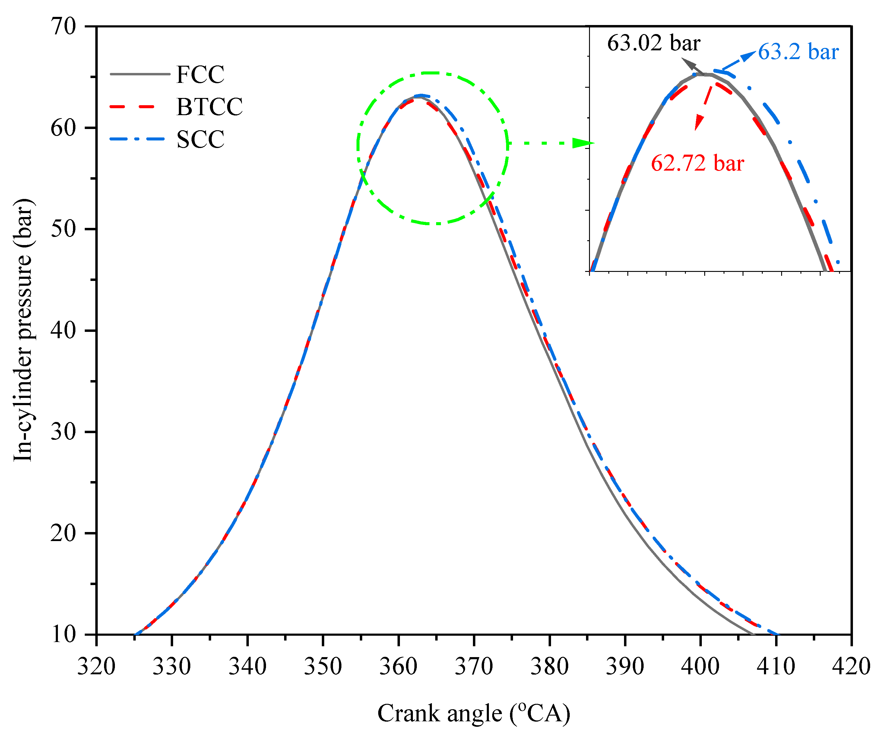
3.3. In-Cylinder Pressure Formation in Modified Combustion Chambers

The preprocessed cylinder pressure data from the simulations for the FCC, BTCC and SCC are presented in Figure 6. Maximum peak pressures for the FCC, BTCC and SCC were recorded as 63.02 bar, 62.72 bar and 63.2 bar at 362 °CA for the FCC and BTCC and at 363 °CA for the SCC, respectively. Higher peak pressures were formed in the SCC compared to the FCC and BTCC. Also, higher combustion pressures were noticed for the modified chambers during the combustion stroke [32]. This is due to the high turbulence created by the modified chambers, which increased the combustion rates [33]. As the pressure is directly proportional to the temperature, high compression temperatures will also develop, thereby reducing the ignition delay [34]. A study conducted by Li et al. [18] also revealed a similar pressure distribution, where increased pressure is noticed for the modified omega combustion chamber (OCC) and SCC compared to the standard FCC. As useful engine work is generated during the combustion stroke, higher temperatures and pressures formed with the modified chambers will improve the engine’s efficiency.

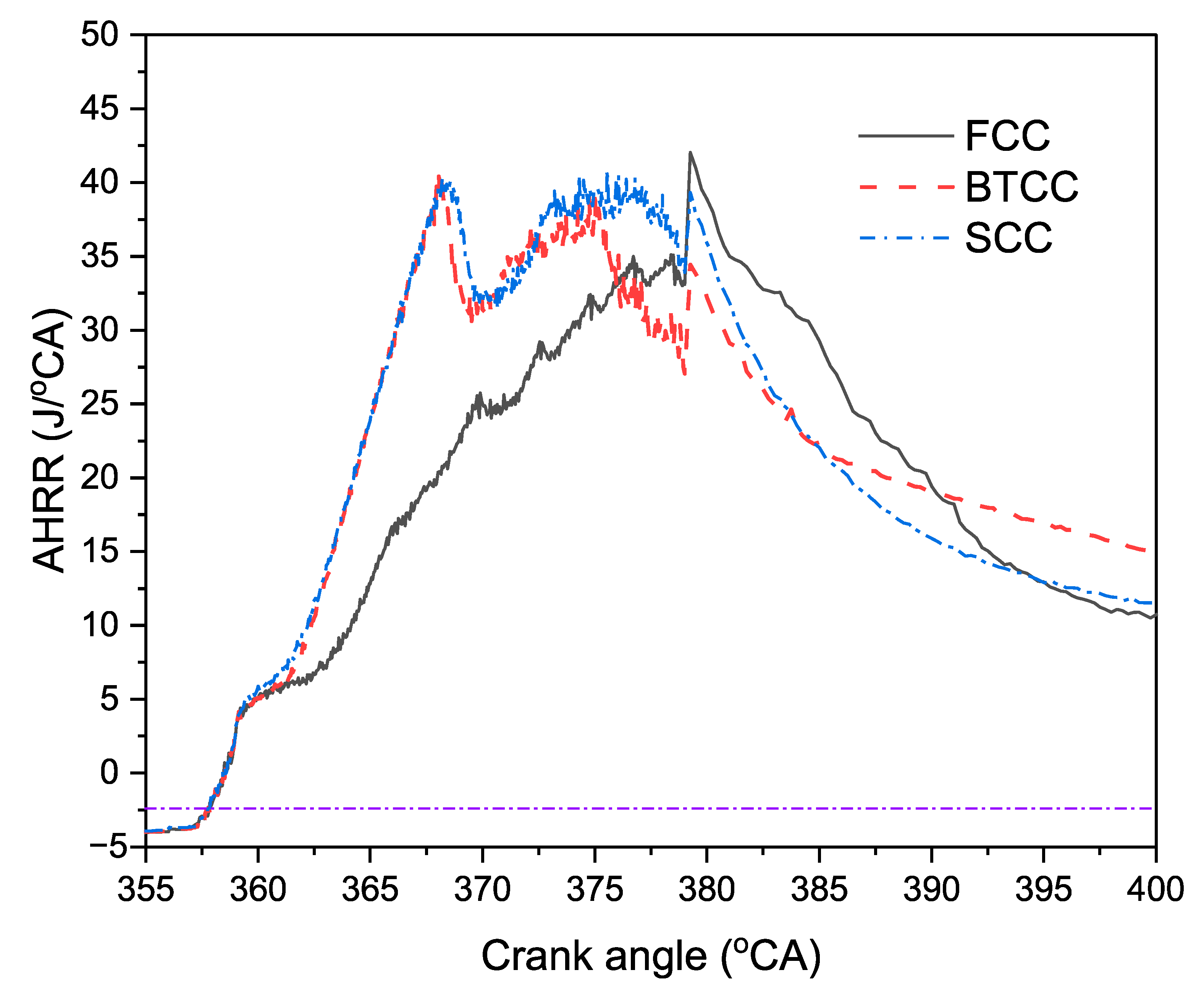
3.4. Analysis of Heat Release Rate for Modified Combustion Chambers

The apparent heat release rates (AHRRs) of the FCC, BTCC and SCC combustion chambers are presented in Figure 7. Figure 7 shows that early combustion happened in the modified chambers because of the increased turbulence that the piston bowl geometry created [35,36]. The formation of elevated temperatures near the compression stroke approached the fuel’s auto-ignition temperature, which caused the early heat release rate (HRR). The injected fuel hit the corners of the piston bowl lips, dispersed inside the chamber and caused better fuel evaporation and distribution. This phenomenon increased the HRR for the modified chambers. The FCC prolonged the HRR because of the fuel accumulation on the cylinder walls, as discussed in the below sections. Though the BTCC and SCC started with an early heat release, the BTCC utilised the higher amounts of available energy, leading to a higher HRR. This was due to the better air–fuel mixing inside the chambers. The modified chambers trapped the fuel near the cylinder axis, leading to early combustion [37].
The cumulative heat release rate (CHHR) plays a vital role in expressing combustion efficiency. Figure 8 represents the CHHR values for different modified chambers across the combustion stroke. The CHHR trend is slightly higher for the modified chambers than for the FCC. The total CHRR values for the BTCC and SCC are 22.6% and 20.9% greater than for the flat chamber. As seen in the HRR graph (Figure 7), early ignition in the modified chambers and higher in-cylinder pressures increased the combustion speeds, leading to a higher CHRR range. Cihan et al. [38] observed a higher CHRR for the Wankel engine due to the larger stroke volume and the lower volume efficiency. The modification of the chambers affects the volumetric flow of fluids and the combustion parameters.
Figure 9, Figure 10 and Figure 11 illustrate the correlation between the in-cylinder pressure and the HRR with respect to the crank angle. The figures show that higher heat release ranges were observed along the compression stroke for the modified chambers compared to the FCC. Peak HRR values and zones were higher for the modified chamber compared to the FCC. The peak turbulence formed inside the chambers will cause combustion distribution along the cylinder chamber and increase the HRR. During the power stroke, the pressure was reduced and higher magnitudes of heat release rates were noticed for the SCC and BTCC. The increase in heat release rates can cause higher NOx. To avoid the high-temperature regions, a lean fuel operating condition with the chamber modifications can reduce the intensity inside the chamber. There is scope to work on the chamber modifications with the reduced NOx, along with fuel consumption control.

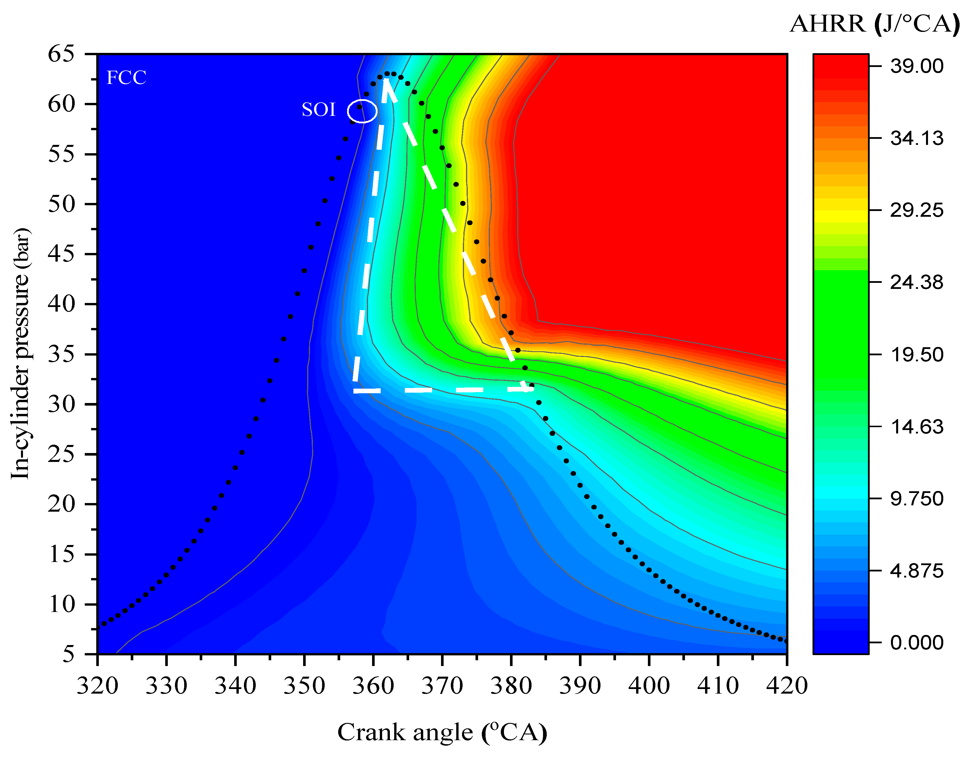
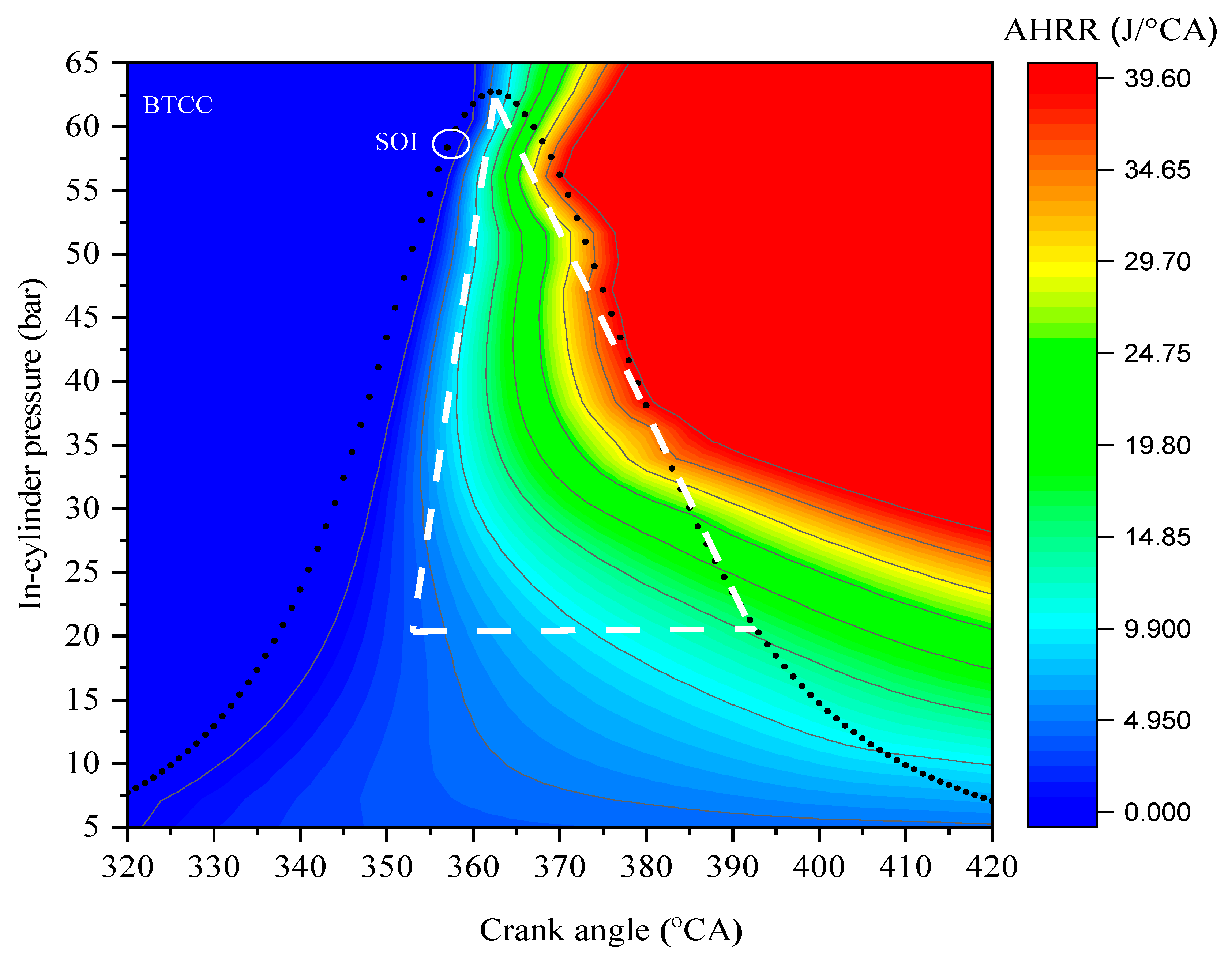
3.5. Analysis of Combustion Parameters on NOx Emissions at 368 °CA

As shown in Figure 12, the temperature at the end of the compression stroke was higher for the modified BTCC and SCC than for the FCC. The recorded peak temperatures for the BTCC, SCC and FCC were 1970 K, 1970 K and 1950 K, respectively. Moreover, the peak turbulent kinetic energy (TKE) for the modified chambers, SCC (797 m2/s2) and BTCC (459 m2/s2), was more than for the FCC (450 m2/s2) at the end of the injection period. This study chose to present the state of combustion events at 368 °CA to analyse the fuel injection rates and their interaction behaviour with the chambers. As shown in the figure, the injected fuel comes into contact with the flat chambers, which disrupts the rate of fuel atomisation and can lead to fuel accumulation. In the case of the modified chambers, the bowl chambers provided quite a space for the fuel to become atomised, avoiding fuel accumulation near the wall chambers [15,39,40]. This is the main reason for the early and high HRRs (Figure 7 and Figure 8) for the modified chambers compared to the FCC. The injection analysis for the different biodiesel fuels and at different injection rates helps investigate the combustion behaviour and emission formation. The source of NO emissions is clearly depicted in Figure 12, where temperature contours are similar to the NO emission contours for all the chambers. The peak NO for the chambers was recorded as 2.8 × 10⁻⁵, 2.18 × 10⁻⁵ and 2.07 × 10⁻⁵ for the FCC, BTCC and SCC, respectively.

3.6. Analysis of Combustion Parameters on NOx Emissions at 428 °CA

Figure 13 illustrates the effect of the combustion parameters on NOx emissions for different piston bowl geometries at 428 °CA. High combustion temperature regions are formed for the SCC (1430 K) compared to the BTCC (1410 K) and FCC (1400 K). As shown in Figure 13, thermal NO has a direct interactive path with temperature. The NO contour is similar to the temperature contour, indicating that the temperature directly influences the NO (thermal NO) emissions. The analysis conducted by Kilic et al. [41] revealed that a decrease in peak combustion temperatures significantly decreased NOx emissions. Moreover, high NO concentrations were noted near the fuel mass regions. This is due to the physical and kinetic energies of the fuel particles inside the chamber. The cold and hot mass fractions increase the particle kinetic velocities, increasing the temperature inside the cylinder [42]. In the expansion stroke, the intensity of the TKE is reduced significantly compared to the starting of the combustion stroke (Figure 12). At 428 °CA, higher NO2 emissions were observed than N2O, and the percentage difference between the chambers was noted as 79%, 100.86% and 90.3%, respectively. As shown before, at 368 °CA, the NO2 emissions were significantly lower than the N2O emissions, which is quite inconsistent. N2O emissions were observed near the outer surfaces of the NO emissions, where the exterior areas are easily oxidised and form N2O emissions. Similarly, in the outer regions of N2O, higher NO2 was observed due to the oxidation and nitration processes, as presented in Figure 13 [43].

3.7. Analysis of Combustion Parameters on NOx Emissions at 480 °CA

Figure 14 presents the effect of combustion parameters on NOx emissions for different piston bowl geometries at 480 °CA. Due to the flat chamber surface of the FCC, the fumes are directed toward the cylinder wall, and combustion happens near the chamber walls. Meanwhile, with the modified chambers, the bowl surfaces obstruct the injected fuel, and combustion occurs inside the cylinder [44]. The combustion process can be clearly analysed through the temperature and TKE profiles. Due to the chamfered edges of the BTCC, the fuel slipped toward the cylinder wall, and the wall-wetting nature of the fuel can be observed near the crevice regions [45]. It can be seen from Figure 12 and Figure 14 that a decrease in peak temperatures was noted for all the chambers during the compression stroke to the end of the combustion stroke. From 368 °CA to 480 °CA, temperatures decreased from 1950 K to 1290 K for the FCC, from 1970 K to 1200 K for the BTCC and from 1970 K to 1240 K for the SCC, respectively. This was mainly due to a change in pressure variation as the piston moved towards the combustion stroke [46]. Moreover, a higher amount of TKE was also noticed at 368 °CA than 480 °CA, which caused rapid combustion and increased the peak temperatures inside the chamber. The formation of less turbulence at 480 °CA impacted the fuel accumulation for all the chambers. The wall-wetting nature can be clearly observed in the FCC on the cylinder head surface, directly correlating with the NO formation [33]. The BTCC showed better combustion rates as it used more fuel during the combustion process than others.
The FCC showed a peak mass fuel fraction of 2.47 × 10⁻² kgfuel/kgmix, whereas the BTCC and SCC showed 1.16 × 10⁻² kgfuel/kgmix and 1.77 × 10⁻² kgfuel/kgmix, respectively. Though the SCC showed higher mass fractions inside the chamber than the BTCC, the mass fractions were situated in the bowl chamber for the SCC. Meanwhile, for the BTCC, the mass fractions were noticed in the squish regions. Adjusting the spray behaviour in the bowl chamber can avoid the fuel accumulation in the bowl chamber of the SCC and can create better combustion [47]. The SCC showed peak NO emissions of 1.01 × 10⁻⁵ kgNO/kgmix compared to the BTCC (9.80 × 10⁻⁶ kgfuel/kgmix) and FCC (8.40 × 10⁻⁶ kgfuel/kgmix). This was due to high TKE and high-temperature zones in the modified chambers. Though the FCC revealed lower peak NO emissions, the peak NO2 emissions were significantly higher than the SCC.

4. Conclusions and Recommendations

This study used the CFD simulation tool to analyse the combustion and emission formation mechanism for the FCC, BTCC and SCC. Reaction models, combustion results and emission quantities were assessed on the validated combustion chamber to investigate the effect of chamber geometries on combustion aspects and emission parameters. The main conclusions are as follows:
(a)
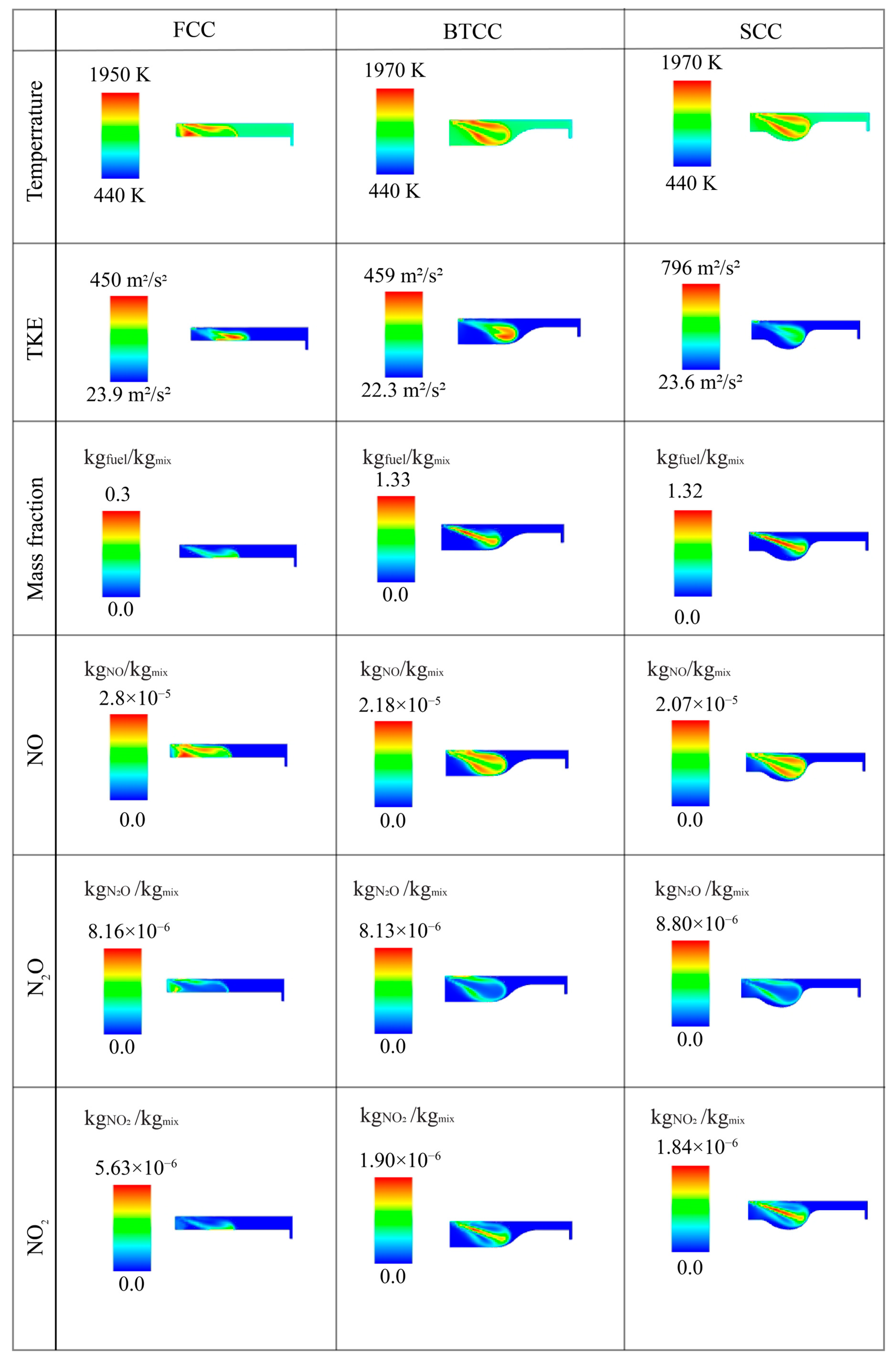
The chamber modifications improved air–fuel mixtures, avoiding fuel pockets. High TKE motions indicate that the BTCC and SCC showed better in-cylinder fluid motions and performance than the FCC.
(b)
The temperature and TKE contours demonstrate combustion at crank angles of 368 °CA, 428 °CA and 480 °CA, and these contours are used to describe the NOx emission pathways.
(c)
NO emissions were high in the regions where high TKE, temperature and unburnt mass fractions were observed. Compared to the FCC, higher NOx emissions were observed in the modified BTCC and SCC due to the generation of higher temperatures.
(d)
From the investigation, the SCC showed better combustion results compared to the FCC and BTCC. The SCC exhibited better combustion through higher in-cylinder pressure, HRR and cumulative HRR than the other chambers. However, higher unburnt mass fractions were observed in this chamber bowl than in the BTCC, which can be controlled by adjusting injection rates and spray angles.
This study recommends investigating lean fuel mixture proportions to reduce the fuel intake inside the chamber, which can help reduce the cylinder temperatures, eventually reducing NOx emissions. This study further recommends investigating bowl geometries with the optimisation of fuel spray, such as by adjusting the fuel injection profile, spray angle and injection timing, which has a better tendency to create complete combustion.

Author Contributions

Conceptualisation, A.T.D. and A.K.A.; methodology, A.T.D. and A.K.A.; software, A.T.D.; validation, A.T.D. and A.K.A.; writing—original draft preparation, A.T.D.; writing—review and editing, A.T.D. and A.K.A.; visualisation, A.T.D. and A.K.A.; supervision, A.K.A. All authors have read and agreed to the published version of the manuscript.

Funding

This research received no external funding.

Institutional Review Board Statement

Not applicable.

Informed Consent Statement

Not applicable.

Data Availability Statement

Data are contained within the article.

Conflicts of Interest

The authors declare no conflicts of interest.

References

  1. Anenberg, S.C.; Miller, J.; Minjares, R.; Du, L.; Henze, D.K.; Lacey, F.; Malley, C.S.; Emberson, L.; Franco, V.; Klimont, Z.; et al. Impacts and mitigation of excess diesel-related NOx emissions in 11 major vehicle markets. Nature 2017, 545, 467–471. [Google Scholar] [CrossRef] [PubMed]
  2. Miao, Z.; Baležentis, T.; Shao, S.; Chang, D. Energy use, industrial soot and vehicle exhaust pollution—China’s regional air pollution recognition, performance decomposition and governance. Energy Econ. 2019, 83, 501–514. [Google Scholar] [CrossRef]
  3. Azad, A.K.; Rasul, M.G.; Khan, M.M.K.; Sharma, S.C.; Hazrat, M.A. Prospect of biofuels as an alternative transport fuel in Australia. Renew. Sustain. Energy Rev. 2015, 43, 331–351. [Google Scholar] [CrossRef]
  4. Hill, S.C.; Douglas Smoot, L. Modeling of nitrogen oxides formation and destruction in combustion systems. Prog. Energy Combust. Sci. 2000, 26, 417–458. [Google Scholar] [CrossRef]
  5. Sungur, B.; Topaloglu, B.; Namli, L.; Ozcan, H.; Ozbey, M. Combustion performance and emissions of diesel/biodiesel blended fuels in a residential reverse flame boiler. Int. J. Glob. Warm. 2017, 13, 183–196. [Google Scholar] [CrossRef]
  6. Panigrahi, T.H.; Sahoo, S.R.; Murmu, G.; Maity, D.; Saha, S. Current challenges and developments of inorganic/organic materials for the abatement of toxic nitrogen oxides (NOx)—A critical review. Prog. Solid State Chem. 2022, 68, 100380. [Google Scholar] [CrossRef]
  7. Li, J.; Han, X.; Zhang, X.; Sheveleva, A.M.; Cheng, Y.; Tuna, F.; McInnes, E.J.L.; McCormick McPherson, L.J.; Teat, S.J.; Daemen, L.L.; et al. Capture of nitrogen dioxide and conversion to nitric acid in a porous metal–organic framework. Nat. Chem. 2019, 11, 1085–1090. [Google Scholar] [CrossRef]
  8. Liu, K.; Yu, Q.; Wang, B.; Qin, Q.; Wei, M.; Fu, Q. Low temperature selective catalytic reduction of nitric oxide with urea over activated carbon supported metal oxide catalysts. Environ. Technol. 2020, 41, 808–821. [Google Scholar] [CrossRef]
  9. Ogden, J.E.; Moore, P.K. Inhibition of nitric oxide synthase—Potential for a novel class of therapeutic agent? Trends Biotechnol. 1995, 13, 70–78. [Google Scholar] [CrossRef]
  10. Azad, A.K.; Rasul, M.G.; Khan, M.M.K.; Sharma, S.C.; Bhuiya, M.M.K. Recent development of biodiesel combustion strategies and modelling for compression ignition engines. Renew. Sustain. Energy Rev. 2016, 56, 1068–1086. [Google Scholar] [CrossRef]
  11. Castoldi, L. An Overview on the Catalytic Materials Proposed for the Simultaneous Removal of NOx and Soot. Materials 2020, 13, 3551. [Google Scholar] [CrossRef] [PubMed]
  12. Attia, A.M.A.; Kulchitskiy, A.R. Influence of the structure of water-in-fuel emulsion on diesel engine performance. Fuel 2014, 116, 703–708. [Google Scholar] [CrossRef]
  13. Ithnin, A.M.; Noge, H.; Kadir, H.A.; Jazair, W. An overview of utilizing water-in-diesel emulsion fuel in diesel engine and its potential research study. J. Energy Inst. 2014, 87, 273–288. [Google Scholar] [CrossRef]
  14. Azad, A.K.; Doppalapudi, A.T.; Khan, M.M.K.; Hassan, N.M.S.; Gudimetla, P. A landscape review on biodiesel combustion strategies to reduce emission. Energy Rep. 2023, 9, 4413–4436. [Google Scholar] [CrossRef]
  15. Doppalapudi, A.T.; Azad, A.K.; Khan, M.M.K. Advanced strategies to reduce harmful nitrogen-oxide emissions from biodiesel fueled engine. Renew. Sustain. Energy Rev. 2023, 174, 113123. [Google Scholar] [CrossRef]
  16. Agarwal, A.K.; Singh, A.P.; García, A.; Monsalve-Serrano, J. Challenges and opportunities for application of reactivity-controlled compression ignition combustion in commercially viable transport engines. Prog. Energy Combust. Sci. 2022, 93, 101028. [Google Scholar] [CrossRef]
  17. Han, S.; Kim, J.; Bae, C. Effect of air–fuel mixing quality on characteristics of conventional and low temperature diesel combustion. Appl. Energy 2014, 119, 454–466. [Google Scholar] [CrossRef]
  18. Vávra, J.; Bortel, I.; Takats, M.; Diviš, M. Emissions and performance of diesel–natural gas dual-fuel engine operated with stoichiometric mixture. Fuel 2017, 208, 722–733. [Google Scholar] [CrossRef]
  19. Doppalapudi, A.; Azad, A.; Khan, M. Combustion chamber modifications to improve diesel engine performance and reduce emissions: A review. Renew. Sustain. Energy Rev. 2021, 152, 111683. [Google Scholar] [CrossRef]
  20. Benajes, J.; Pastor, J.V.; García, A.; Monsalve-Serrano, J. An experimental investigation on the influence of piston bowl geometry on RCCI performance and emissions in a heavy-duty engine. Energy Convers. Manag. 2015, 103, 1019–1030. [Google Scholar] [CrossRef]
  21. Li, J.; Yang, W.; An, H.; Maghbouli, A.; Chou, S. Effects of piston bowl geometry on combustion and emission characteristics of biodiesel fueled diesel engines. Fuel 2014, 120, 66–73. [Google Scholar] [CrossRef]
  22. Rakopoulos, C.; Kosmadakis, G.; Pariotis, E. Investigation of piston bowl geometry and speed effects in a motored HSDI diesel engine using a CFD against a quasi-dimensional model. Energy Convers. Manag. 2010, 51, 470–484. [Google Scholar] [CrossRef]
  23. Azad, A.K.; Halder, P.; Wu, Q.; Rasul, M.G.; Hassan, N.M.S.; Karthickeyan, V. Experimental investigation of ternary biodiesel blends combustion in a diesel engine to reduce emissions. Energy Convers. Manag. X 2023, 20, 100499. [Google Scholar] [CrossRef]
  24. Kale, P. Combustion of biodiesel in CI engine. Int. J. Appl. Res. 2017, 3, 145–149. [Google Scholar]
  25. Nabi, M.N.; Rasul, M.G.; Anwar, M.; Mullins, B.J. Energy, exergy, performance, emission and combustion characteristics of diesel engine using new series of non-edible biodiesels. Renew. Energy 2019, 140, 647–657. [Google Scholar] [CrossRef]
  26. Doppalapudi, A.T.; Azad, A.K.; Kamal Khan, M.M. Analysis of Improved In-Cylinder Combustion Characteristics with Chamber Modifications of the Diesel Engine. Energies 2023, 16, 2586. [Google Scholar] [CrossRef]
  27. Han, Z.; Reitz, R.D. Turbulence modeling of internal combustion engines using RNG κ-ε models. Combust. Sci. Technol. 1995, 106, 267–295. [Google Scholar] [CrossRef]
  28. Varol, Y.; Oztop, H.F.; Firat, M.; Koca, A. CFD modeling of heat transfer and fluid flow inside a pent-roof type combustion chamber using dynamic model. Int. Commun. Heat Mass Transf. 2010, 37, 1366–1375. [Google Scholar] [CrossRef]
  29. Jaichandar, S.; Annamalai, K. Effects of open combustion chamber geometries on the performance of pongamia biodiesel in a DI diesel engine. Fuel 2012, 98, 272–279. [Google Scholar] [CrossRef]
  30. Jaichandar, S.; Annamalai, K. Influences of re-entrant combustion chamber geometry on the performance of Pongamia biodiesel in a DI diesel engine. Energy 2012, 44, 633–640. [Google Scholar] [CrossRef]
  31. Splitter, D.; Wissink, M.; Kokjohn, S.; Reitz, R.D. Effect of Compression Ratio and Piston Geometry on RCCI Load Limits and Efficiency, 2012. SAE Technical Paper 2012-01-0383. 2012. Available online: https://saemobilus.sae.org/content/2012-01-0383/ (accessed on 21 January 2024).
  32. Channappagoudra, M.; Ramesh, K.; Manavendra, G. Comparative study of standard engine and modified engine with different piston bowl geometries operated with B20 fuel blend. Renew. Energy 2019, 133, 216–232. [Google Scholar] [CrossRef]
  33. Gafoor, C.A.; Gupta, R. Numerical investigation of piston bowl geometry and swirl ratio on emission from diesel engines. Energy Convers. Manag. 2015, 101, 541–551. [Google Scholar] [CrossRef]
  34. Tay, K.L.; Yang, W.; Zhao, F.; Yu, W.; Mohan, B. Numerical investigation on the combined effects of varying piston bowl geometries and ramp injection rate-shapes on the combustion characteristics of a kerosene-diesel fueled direct injection compression ignition engine. Energy Convers. Manag. 2017, 136, 1–10. [Google Scholar] [CrossRef]
  35. Karthickeyan, V. Effect of combustion chamber bowl geometry modification on engine performance, combustion and emission characteristics of biodiesel fuelled diesel engine with its energy and exergy analysis. Energy 2019, 176, 830–852. [Google Scholar] [CrossRef]
  36. Karthickeyan, V.; Thiyagarajan, S.; Ashok, B.; Geo, V.E.; Azad, A. Experimental investigation of pomegranate oil methyl ester in ceramic coated engine at different operating condition in direct injection diesel engine with energy and exergy analysis. Energy Convers. Manag. 2020, 205, 112334. [Google Scholar] [CrossRef]
  37. Prabhakaran, P.; Saravanan, C.G.; Vallinayagam, R.; Vikneswaran, M.; Muthukumaran, N.; Ashok, K. Investigation of swirl induced piston on the engine characteristics of a biodiesel fueled diesel engine. Fuel 2020, 279, 118503. [Google Scholar] [CrossRef]
  38. Cihan, Ö.; Doğan, H.E.; Kutlar, O.A.; Demirci, A.; Javadzadehkalkhoran, M. Evaluation of heat release and combustion analysis in spark ignition Wankel and reciprocating engine. Fuel 2020, 261, 116479. [Google Scholar] [CrossRef]
  39. Taghavifar, H.; Khalilarya, S.; Jafarmadar, S. Engine structure modifications effect on the flow behavior, combustion, and performance characteristics of DI diesel engine. Energy Convers. Manag. 2014, 85, 20–32. [Google Scholar] [CrossRef]
  40. Varun; Singh, P.; Tiwari, S.K.; Singh, R.; Kumar, N. Modification in combustion chamber geometry of CI engines for suitability of biodiesel: A review. Renew. Sustain. Energy Rev. 2017, 79, 1016–1033. [Google Scholar] [CrossRef]
  41. Kilic, G.; Sungur, B.; Topaloglu, B.; Ozcan, H. Experimental analysis on the performance and emissions of diesel/butanol/biodiesel blended fuels in a flame tube boiler. Appl. Therm. Eng. 2018, 130, 195–202. [Google Scholar] [CrossRef]
  42. Ambedkar, P.; Dutta, T. CFD simulation and thermodynamic analysis of energy separation in vortex tube using different inert gases at different inlet pressures and cold mass fractions. Energy 2023, 263, 125797. [Google Scholar] [CrossRef]
  43. Rayaroth, M.P.; Aravindakumar, C.T.; Shah, N.S.; Boczkaj, G. Advanced oxidation processes (AOPs) based wastewater treatment—Unexpected nitration side reactions—A serious environmental issue: A review. Chem. Eng. J. 2022, 430, 133002. [Google Scholar] [CrossRef]
  44. Cao, L.; Bhave, A.; Su, H.; Mosbach, S.; Kraft, M.; Dris, A.; McDavid, R.M. Influence of Injection Timing and Piston Bowl Geometry on PCCI Combustion and Emissions. SAE Int. J. Engines 2009, 2, 1019–1033. [Google Scholar] [CrossRef]
  45. He, X.; Li, Y.; Sjöberg, M.; Vuilleumier, D.; Ding, C.-P.; Liu, F.; Li, X. Impact of coolant temperature on piston wall-wetting and smoke generation in a stratified-charge DISI engine operated on E30 fuel. Proc. Combust. Inst. 2019, 37, 4955–4963. [Google Scholar] [CrossRef]
  46. Lee, D.D.; Bendana, F.A.; Nair, A.P.; Danczyk, S.A.; Hargus, W.A.; Spearrin, R.M. Exploiting line-mixing effects for laser absorption spectroscopy at extreme combustion pressures. Proc. Combust. Inst. 2021, 38, 1685–1693. [Google Scholar] [CrossRef]
  47. Jaichandar, S.; Thamaraikannan, M.; Yogaraj, D.; Samuelraj, D. A comprehensive study on the effects of internal air jet piston on the performance of a JOME fueled DI diesel engine. Energy 2019, 185, 1174–1182. [Google Scholar] [CrossRef]
Figure 1. Schematic diagram of the experimental setup and numerical study.
Fire 07 00035 g001
Figure 2. Piston bowl chambers: (a) FCC; (b) SCC; (c) BTCC.
Fire 07 00035 g002
Figure 3. Engine characteristics of diesel engine at 1500 rpm: (a) performance parameters; (b) emissions parameters.
Fire 07 00035 g003
Figure 4. Comparison of experimental HRR with simulated AHRR at 1500 rpm for FCC chamber.
Fire 07 00035 g004
Figure 5. Analysis of variation in in-cylinder pressure for experimental and simulation results at 1500 rpm.
Fire 07 00035 g005
Figure 6. In-cylinder pressure formation for the modified chambers.
Fire 07 00035 g006
Figure 7. Comparison of AHRR for FCC, BTCC and SCC at 1500 rpm.
Fire 07 00035 g007
Figure 8. Variation in cumulative HRR for FCC, BTCC and SCC.
Fire 07 00035 g008
Figure 9. In-cylinder pressure vs. AHRR for FCC.
Fire 07 00035 g009
Figure 10. In-cylinder pressure vs. AHRR for BTCC.
Fire 07 00035 g010
Figure 11. In-cylinder pressure vs. AHRR for SCC.
Fire 07 00035 g011
Figure 12. Effect of combustion parameters on NOx emissions at 368 °CA.
Fire 07 00035 g012
Figure 13. Effect of combustion parameters on NOx emissions at 428 °CA.
Fire 07 00035 g013
Figure 14. Effect of combustion parameters on NOx emissions at 480 °CA.
Fire 07 00035 g014
Table 1. Engine specifications.
Engine Specifications
TypeKubota V3300
Bore and stroke98 mm × 110 mm
Compression ratio22.6:1
FuelDiesel
Cooling systemWater cooled
Speed1500 rpm
Disclaimer/Publisher’s Note: The statements, opinions and data contained in all publications are solely those of the individual author(s) and contributor(s) and not of MDPI and/or the editor(s). MDPI and/or the editor(s) disclaim responsibility for any injury to people or property resulting from any ideas, methods, instructions or products referred to in the content.

