Article

Effect of Surface Reaction on the Distribution Characteristics of Temperature and OH Radicals in Microchannel Combustion

1
Key Laboratory of Electromechanical Equipment Safety in Western Complex Environment for State Market Regulation, Chongqing Special Equipment Inspection and Research Institute, Chongqing 401121, China
2
College of Mechanical and Vehicle Engineering, Chongqing University, Chongqing 400044, China
3
School of Petroleum and Natural Gas Engineering, School of Energy, Changzhou University, Changzhou 213164, China
*
Authors to whom correspondence should be addressed.
Submission received: 3 December 2023 / Revised: 13 January 2024 / Accepted: 21 January 2024 / Published: 27 February 2024
(This article belongs to the Special Issue Advanced Technology in Clean Combustion)

Abstract

:
Microchannel burners suffer from low combustion efficiency and poor stability in applications. In order to explore the effect of wall reaction on methane/air premixed combustion performances in the microchannel, the effects of wall activity, inlet velocity, pressure, and equivalence ratio on the temperature and radical distribution characteristics were studied by CFD computational simulations. It is found that as the reaction pressure increases, there are more free-radical collisions, causing the reaction temperature to rise. The OH radicals participate in the reaction at the active near wall so that the mass fraction of the OH radical on the active wall is lower than that on the inert wall. As the equivalence ratio increases from 0.6 to 1.2, the high-temperature regions increase but the maximum temperature decreases. The mass fraction of OH radical increases with the increase of the equivalence ratio, and the increase of OH radical near the inert wall is larger than that of the active wall. As the flow rate increases, the disturbance increases, and the combustion reaction becomes more intense, resulting in an increase in the temperature and the mass fraction of OH radicals. The mass fraction of H, O, OH, and CH3 radicals in the inert wall was slightly higher than that in the active wall, in which the peak mass fraction of CH3 radical appeared at the axial position closest to the entrance, while the other three radicals reached the peak at about the same axial position. This study provides a reference for combustion stability in microcombustors.

1. Introduction

The Microelectro-Mechanical System (MEMS) was first developed from microsensors in the 1970s and has gradually become a cutting-edge technology in the 21st century due to its multiple advantages such as small space occupation, low power consumption, and lightweight [1]. MEMS has been widely used in optics, biology, automobiles, computers, aerospace, and the military, among other fields [2,3,4]. At present, important results have been achieved, such as chemical and biological microanalytical instruments, micro-optical scanners, microgas turbines, microrobots, etc., which have become an important research topic of global concern [5,6,7]. With the development of MEMS technology, the development of an efficient, durable, and miniaturized energy supply system has become an important goal in this field [8,9].
The micro power source provides energy and power to MEMS and is one of the core components. For the characteristics of small size and continuous use of MEMS, portable micropower sources must meet the following basic requirements [10]: ① high energy density; ② higher output power and flexible adjustment; ③ simple structure; ④ long service life and recycling. At present, many micropower sources still use chemical batteries such as alkaline batteries. However, the energy density of the most advanced lithium-ion batteries is lower than that of hydrocarbon fuels such as methane and diesel [11,12]. Therefore, hydrocarbon fuel has a significant advantage in energy density [13].
As a power device, the main function of microcombustors is to convert the chemical energy of the fuel into thermal energy through combustion. The development and application of efficient and stable microcombustors has become a current hot issue [14,15]. In order to obtain high energy output power and energy conversion efficiency, Zuo et al. designed a microplanar combustor with cavity microplanes and studied the effects of the combustion chamber structure, tube outlet structure, and cathode channel structure on combustion performance [16,17,18,19]. It is found that optimizing the structure of the microcombustor to improve the thermal performance of the microcombustor is an effective method.
Compared with chemical batteries, hydrocarbon fuelshave the characteristics of high energy density and environmental protection [20,21]. However, there are still some problems in the application process of hydrocarbon fuel-based microchannel burners [22]: the residence time of fuel in the microchannel burner is short and the combustion efficiency is low; the surface area of microchannels is large but the volume is small, the surface heat dissipation is large, and the combustion stability is poor; the size of the microchannel is close to the flameout diameter of fuel, which leads to the instability of combustion; the loss of free radicals in the microchannel is large. When the size of the burner is reduced to a small scale, the surface-to-volume ratio (S/V) of the burner increases sharply, and the effect of the wall action on the combustion increases significantly [23,24]. The effect of wall action on gas combustion is mainly focused on the ignition, flame propagation, and free-radical distribution in the flat wall or microchannel, and it even causes flameout.
The main causes of free-radical quenching on the wall of premixed methane combustion flames in microscale combustion are thermodynamic quenching and kinetic quenching (chemical quenching) [22]; that is, the heat loss of the wall and the occurrence of wall adsorption of radicals [25,26]. Both thermal quenching and free-radical quenching need to be avoided, so the research on the two flameout methods has become the top priority in the field of microscale combustion. In cold-wall conditions (<500 K), the heat dissipation of the microchannel wall to the outside is stronger, so the thermal quenching effect of radicals is dominant [27,28]. The study of thermal quenching is essentially a heat-transfer problem, which can be solved from the heat-transfer properties of the reactor wall materials or by applying various flame-stabilization measures in conventional burners to microscale combustion, such as preheating the gas [29,30], constructing the reflux zone, adopting bluff bodies to stabilize the combustion [31,32], etc. The research on free-radical quenching is more biased towards chemical kinetics. Free-radical quenching is essentially the result of the coupling effect between wall-reaction and gas-phase (or liquid-phase) combustion reactions, so the research focuses on promoting combustion reactions by changing this coupling effect. Therefore, the study of the wall-reaction mechanism is necessary.
A large number of intermediate components are produced during the combustion process, and some components are of great significance for the study of the flame formation and development process [33,34,35]. It is generally believed that the distribution of OH radicals and CH radicals can show flame-peak surfaces [36,37,38]. Therefore, the free radicals generated during the combustion process and their concentration distribution can reflect information such as the fine structure of the combustion flame, partial combustion-reaction mechanism, and combustion speed [39,40].
Kim [41] discovered the reasons for the quenching of the premixed methane/air flame near the wall through experimental studies, which are heat loss and free-radical inactivation at the wall. It is found that there are three different mechanisms for flameout. At wall temperatures of 100–350 °C, the main cause of flameout is heat loss. When the wall temperature reaches above 400 °C, the chemical reaction of free radicals on the wall is the main reason for flameout. When the wall temperature exceeds 600 °C, the homogeneous chemical reaction eliminates the influence of free-radical movement, thus becoming less prone to flameout, and the higher the temperature, the smaller the flameout distance. Fan [42] used the planar laser-induced fluorescence technique to investigate active groups OH and CH of combustion flames in the microburner during repeated ignition and flameout propagation and made the wall of the microburner form a high-temperature wall with a uniform temperature by infrared heating. In addition, Fan [43,44] also used the OH-PLIF multi-line method to obtain the temperature distribution in the microburner during repeated ignition and flameout. Suzuki [45] used the OH-PLIF measurement technique to investigate the effect of different wall conditions, such as different temperatures and different materials, on the OH radical distribution near the wall of the premixed methane/air combustion flames between parallel plates. The results show that the unstable propagation of combustion flame appears in the narrow gap as the decrease of the wall distance between two parallel plates, and the unstable propagation phenomenon is different at different wall temperatures [46]. In addition, it was found that the higher the OH concentration near the wall, the smaller the quenching distance.
The OH radical concentration near the wall is the main factor determining the quenching distance, and the peak OH radical concentration of the flame represents the strength of the central flame. A higher concentration of OH radicals can be maintained near the smooth wall as opposed to the rough-surface wall, so the quenching distance is also smaller. Prakash [47] raised the wall temperature (700–1100 K) to analyze the concentration of OH radicals in a low-pressure flame on the wall of different materials such as alumina, quartz, and platinum at a distance of several millimeters. The results prove the importance of surface chemical reactions. The use of inert materials such as quartz and alumina as a burner wall maintains a higher concentration of OH radicals in the combustion flame as compared to the use of reactive materials such as platinum. The same effect can be achieved by increasing the wall temperature of the microburner. Daivs [48] measured the concentration of the OH radical near the wall and found that the concentration of OH radicals decreased with the increase of catalytic activity of the wall.
In summary, although the chemical quenching caused by radical deactivation has gradually attracted attention, there is a lack of work on the analysis of the behavior of radicals near the wall and the mechanism of their influence on flame propagation and flameout. The existing research focuses on the description of the combustion phenomenon, while reports on the causes of radical quenching for each operating condition are relatively scarce, and there is a lack of exploring the causes of radical quenching by combining the temperature distribution in the microchannel with OH radical distribution. Few studies have investigated the effects of pressure, equivalence ratio, and inlet velocity on the temperature distribution and OH radicals in the microchannel, which will affect the thermal efficiency of the microburner, so it is necessary to study.
In this paper, the effect of the wall reaction on the free-radical distribution of premixed methane/air flames was studied by numerical simulation under the effect of eliminating thermal quenching. The effects of pressure, equivalent ratio, and inlet velocity on the temperature and OH radical distribution in the microchannel were investigated. Premixed methane/air combustion is a very complex process at a microscale. The purpose of studying it is to better provide technical support for the optimization and practical application of microcombustion technology.

2. Materials and Methods

2.1. Physical Model

The physical model used in this study is composed of two parallel, infinitely thick plates, as shown in Figure 1, forming a rectangular microchannel with a length (“L”) and height (“H”) perpendicular to the direction of the straight plane and infinite thickness. It is assumed that all quantities are equal along the thickness direction, so the model can be simplified to a two-dimensional structure. This work focuses on the influence of wall reactions on OH radicals in premixed methane/air flames, so the thickness of two parallel plates is set to 0 to eliminate the heat-transfer effect of wall. In order to highlight the influence of chemical reaction, the distance between the two walls is reduced to 1 mm. Furthermore, the plate is set to be isothermal with infinite thermal conductivity, so thermal cycle is not considered in this model. The premixed and preheated methane/air mixture enters the gap between two parallel plates, which is symmetrical relative to the central axis; that is, the height direction is the same up and down. Therefore, in order to reduce the calculation, only half of the region needs to be considered in the calculation process, and the selected region is analyzed by two-dimensional Cartesian coordinates as shown in Figure 1. During the calculation process, the premixed methane/air gas flows uniformly from the left side of the microchannel into the interplate for combustion at a certain speed.

2.2. Mathematical Model

In this study, it is assumed that methane/air has been fully mixed before it enters the microchannel, ignoring the dissipative effect caused by gas viscosity, as well as the body force and radiation effect of gas. The Dufour effect is ignored in the energy equation, and the Soret effect and pressure diffusion are ignored in the component equation. Based on the above descriptions and assumptions, the conservation equations of mass, momentum, and components, and the ideal gas state equation, are as follows.
The continuity equation is shown in Equation (1).
ρ t + ρ v U = 0
where ρ is the fluid density (kg·m−3), t is the time (s), is the spatial gradient operator, is the vector dot product, and U is the absolute velocity (m·s−1).
The momentum equation is shown in Equations (2) and (3).
The momentum conservation equation in x direction is:
ρ D u D t = P x + x 2 μ u x 2 3 μ v + y μ u y + v x
The momentum conservation equation in y direction is:
ρ D v D t = P y + y 2 μ u y 2 3 μ v + x μ u y + v x
where P is the absolute pressure (Pa), μ is the dynamic viscosity (N·s·m−2), x and y are the axial and transverse positions, and u and v are the axial and transverse velocities (m·s−1), respectively.
The composition conservation equation is shown in Equation (4).
ρ Y i t + ρ u Y i x + ρ v Y i y = x ρ D i , m Y i x + y ρ D i , m Y i y R i
where Y i , D i , m (m2·s−1), and R i (kg·m−3·s−1) are the mass fraction, diffusivity, and generation rate of the i component, respectively.
The energy-conservation equation is shown in Equation (5).
c P ρ T t + ρ u T x + ρ v T y = x λ T x + y λ T y i = 1 N h i R i
where c P is the heat capacity at constant pressure (J·K−1·mol−1), T is the temperature (K), λ is the thermal conductivity (W·m−1·K−1), h i is the enthalpy of the i component (J·kg−1), and N is the gas type.
The ideal gas-state equation is shown in Equation (6).
P = ρ R T i = 1 N Y i M i
where R is the universal gas constant (J·mol−1·K−1) and M i is the molar mass of the i component (kg·mol−1).
The equation used for surface-reaction-rate calculation is shown in Equation (7).
R s , i = k = 1 K s v i k k f k j = 1 N g + N s X j v j k , i = 1 , , N g + N s
where v i k is the stoichiometric coefficient of the i component at the k step reaction, k f k is the forward-rate constant of the k reaction (kg·mol−1·s), [Xj] is the mole concentration of the j component (mol·m−2), and N g and N s are the amounts of components in the gas phase and wall surface, respectively.
k f k , a = S 0 , i 1 S 0 , i / 2 1 Γ τ R T 2 π M i
where S 0 , i is the adhesion coefficient of the i component and Γ is the surface-site density of chromium (3.170 × 10⁻⁹ mol·cm−2). γ-Al2O3 (1.360 × 10⁻⁹ mol·cm−2) is the distance between the atoms that are estimated to pass through the lattice.
k f k , s = A k T β k exp E k R T s
Here, the superscript τ is the number of positions occupied by the reacting component. The subscripts a and s represent adsorption and surface reaction, respectively.
X j = Γ θ j , j = 1 , , N s
where θ is the surface coverage.

2.3. Reaction Mechanism

The gas-phase reaction mechanism is based on the GRI-mech 3.0 methane combustion mechanism, which includes 50 components and 309 elementary reactions (Ar, C3H8, and C3H7 components and related reactions have been eliminated). The surface-reaction mechanism is shown in Table 1, including four surface components and 10 elementary reactions. Vlachos [49] performed a sensitivity analysis of ignition and quenching processes near the active and inert surface. The results show that CH3/H and H/OH/O radicals are important for ignition and quenching, respectively. Therefore, CH3, H, OH, and O are used to construct the surface reaction mechanism. Based on the estimation of transition state theory, the pre-exponential factor of each radical recombination elementary reaction is about 1013 s−1.
For the wall-reaction mechanism, CHEMKIN thermodynamic and transport data were used [50]. There are no thermodynamic data on the surface species for the experimental materials (chromium, γ-Al2O3, quartz, etc.) except for common catalysts (Pt, Pd, etc.). However, the use of isothermal boundary conditions for the wall in this work makes it unnecessary to obtain thermodynamic data for the adsorbed substances on the surface or to calculate the heat released by the surface reaction. The adhesion coefficient S0 of each radical depends on the binding energy of the adsorbate to the metal, since higher binding energy results in easier adsorption on the surface. From the d-band theory, the binding strength of the adsorbate depends on the position of the metal d-band center relative to the Fermi level [51]. The closer the metal to the left in the periodic table, the higher the center of the d-band moves upward relative to the Fermi level. Therefore, it has stronger adhesiveness, and it is reasonable to set S0 = 1 in samples of noble metals Pt and Pd for alloys of chromium, which are filled with more antibonding states than chromium. The adhesion coefficient is related to γ-Al2O3 as an inert surface. For the active wall (S0 = 1), its reaction with OH radicals is the strongest, while for the inert wall (S0 = 0), its reaction with OH radicals is the weakest. Thus, OH radicals do not adsorb but rebound when they touch the wall.
Table 1. Heterogeneous mechanism and kinetic parameters [51].
NOReactionsS0 or A (s−1)βE (kJ·mol−1)
1CH3 + * ⇒ CH3*1
2H + * ⇒ H*1
3O + * ⇒ O*1
4OH + * ⇒ OH*1
52CH3* ⇒ C2H6 + 2*101300
6CH3* + H* ⇒ CH4 + 2*101300
72H* ⇒ H2 + 2*101300
82OH* ⇒ H2O + O* + *101300
92O* ⇒ O2 + 2*101300
10OH* + H* ⇒ H2O + 2*101300
S0 is the adhesion coefficient; A is the pre-exponential factor (s−1); β is the temperature index; E is the activation energy (kJ·mol−1).

2.4. Calculation Method

ANSYS Fluent 17.0 software is used as the CFD numerical calculation platform. The software runs on the computing workstation (main frequency 2.6 GHZ, 22 cores, 44 threads), and 40 threads are called in each calculation. The microburner studied in this simulation has a microchannel length (L) of 5 mm and a height (H) of 1 mm, as shown in Figure 1. The calculation area is the entire microburner, where a non-uniform grid is used in the X direction and a uniform grid is used in the Y direction. The number of grids in the X and Y directions are 200 and 25, respectively, and the total number of grids is 5000, as shown in Figure 2. In order to ensure the accuracy of the calculation, a fine grid quality (Skewness = 0.6; Aspect Ratio = 5:4; Growth Rate = 1.1) is selected. The time step used in the iterative calculation is 1.0 × 10⁻⁵ s, and the relaxation factors are selected as 0.3 for pressure, 1 for density, 0.6 for momentum, and 0.8 for the rest. In order to investigate the effect of wall activity on OH radicals in the methane/air combustion reaction, active walls and inert walls were established in this study.
Ronny and Kuo [52] found that the Reynolds number of the fluid in microburners is greater than 500 can be regarded as turbulent flow. The Reynolds number in this work is Re < 100, and the mean free path of the premixed gas molecules is much smaller than the feature size of the microchannel, so the premixed gas is treated as an incompressible laminar flow.
The solution is solved by component transport. In the boundary conditions, the inlet adopts the velocity inlet, the outlet is set as the pressure outlet, and the wall is set to constant temperature. The density of the fluid is calculated according to the ideal gas-state equation, and the weighted average method is used to calculate the other parameters of the premixed gas.
The specific equation at the entrance is Equation (11):
Y i = Y i ϕ , ϕ = 1.0 , u = 6 u 0 d 2 d y y , v = 0 , T = T s
where Y i , ϕ , u , u 0 , v , d , T , T s are the mass fraction of inlet premixed gas, the premixed gas-equivalence ratio, flow velocity in x direction at the entrance, average flow velocity in the x direction of the entrance, flow velocity in the y direction at the entrance, the height of the microchannel H, the set of the inlet premixed gas temperature (1273 K), and the set of wall temperature (1273 K), respectively.
The specific equation at the outlet is Equation (12):
F x i = 1 = 0 ,     F = u , v , Y , T
The specific equation at the wall is Equation (13):
u = v = 0 ,     T = T s ,     - ρ D j Y i y s u r f a c e = W j M j A N A , Y N 2 y s u r f a c e = 0
The specific equation at the central axis is Equation (14):
F x y = d / 2 = 0 ,   F = u , Y , T , ν = 0
i are variety of components, such as H2, O2, H2O, H, O, OH, HO2, H2O2, etc.

2.5. Method Validation

In order to ensure the reliability of the simulation calculation, the selected methods are verified, mainly including grid independence verification and numerical method feasibility verification.

2.5.1. Grid Independence Verification

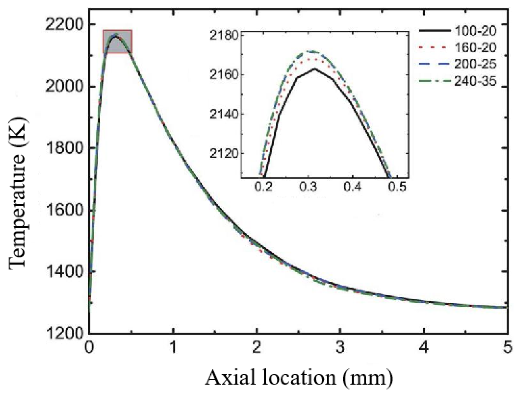
For simulations, no more grids should be used, as they increase the truncation error, as well as the computational effort. A grid size that is too large is bound to increase the calculation error, so in order to take into account both small errors and small calculation efforts, it is necessary to choose a reasonable number of grids, as well as a reasonable grid size. However, an excessively large grid size will inevitably increase the calculation error. Therefore, in order to take into account both small errors and small calculation amount, it is necessary to select a reasonable number of grids and a reasonable grid size. The grid number used in this study is 200 × 25. In order to verify the grid independence, the other three groups of grid numbers, 100 × 20, 160 × 20, and 240 × 35, are selected for iterative calculations to investigate the effect of different grid sizes on the temperature in the microchannel axis.
It can be seen from Figure 3 that the temperature is the lowest when the grid number is 2000 and the curve is not smooth enough to reflect the real temperature. However, as the number of grids increases to 5000, the temperature is higher and convergence is achieved, which can provide the required accuracy. Finally, after increasing the number of grids to 8400, it is found that the temperature and the smoothness of the curve did not change much compared to the number of 5000 grids. Considering the calculation accuracy and calculation effort, the number of 5000 grids was finally adopted in this study.

2.5.2. Feasibility Analysis of Calculation Method

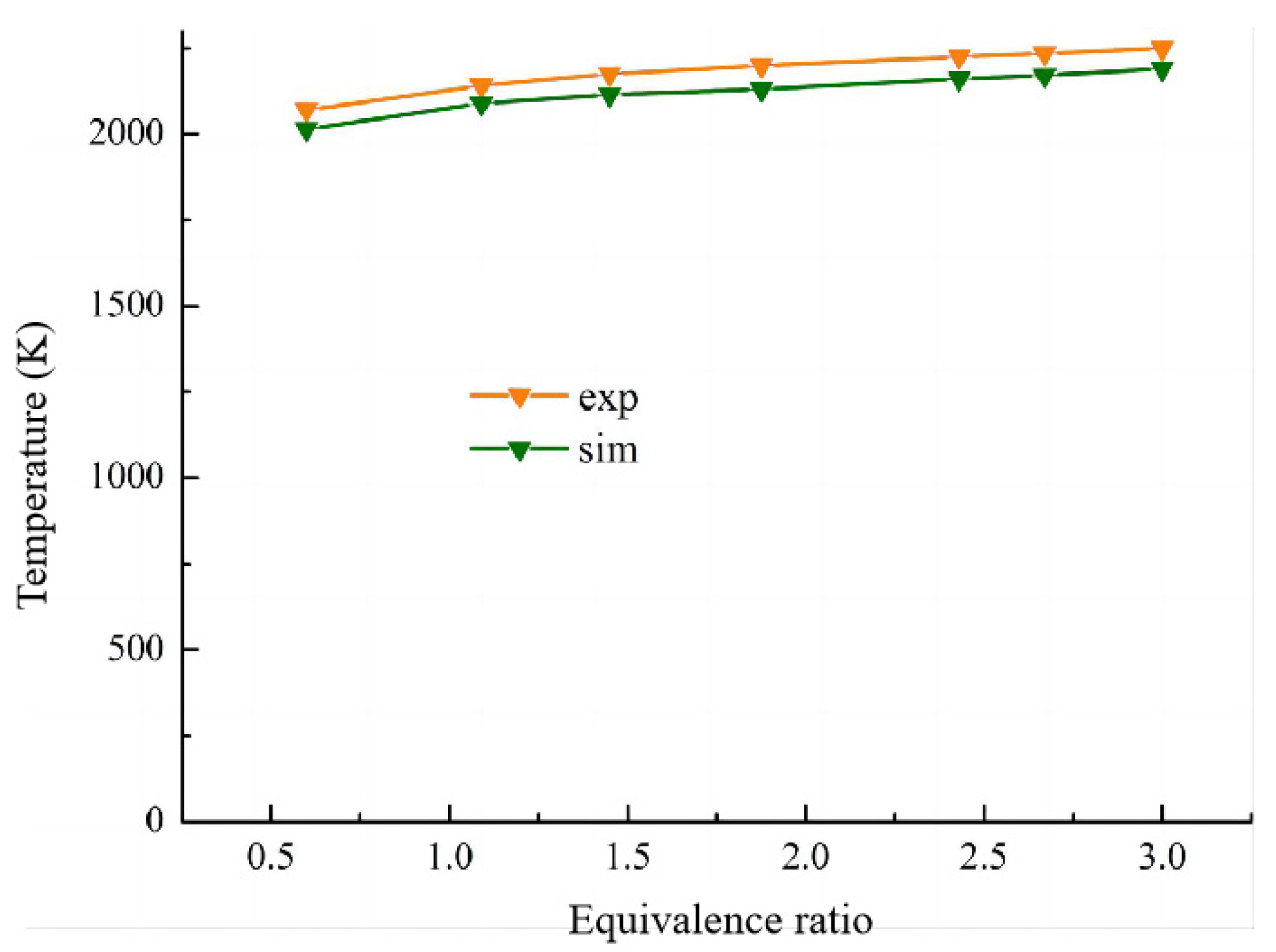
This study is the next step of research based on a large number of current references. It is very important to choose a reasonable reaction mechanism, correct kinetic model, and feasible experimental scheme. Therefore, the calculation method used in this work is compared with the experimental results to identify the rationality and correctness of the simulation method.
The experimental results of Chen [53] are compared with the simulation results of this work. The burner used in the experiment is a horizontal rectangular pipe made of quartz glass with dimensions of 500 mm × 110 mm × 80 mm, which is located on the metal frame. The mathematical models and reaction mechanisms used in the simulations are those mentioned above.
As shown in Figure 4, the simulated and experimental growth trends are the same, and the temperature changes at different inlet velocities are consistent, with only a 3.18% difference in the maximum temperature. Therefore, it can be determined that the reaction mechanism and calculation method used in this work are feasible and applicable.

3. Result and Discussion

3.1. Effect of Different Reaction Pressures

The effect of reaction pressure on the combustion process in a microspace presents complex nonlinear characteristics. A higher reaction pressure is beneficial to improve the oxyhydrogen combustion efficiency of the microcombustor and weaken the adverse effect of surface heat-transfer loss on the combustion stability and adequacy. However, the dominant role of the chain termination elementary reaction under high pressure leads to an increase in the ignition lag time [54,55].
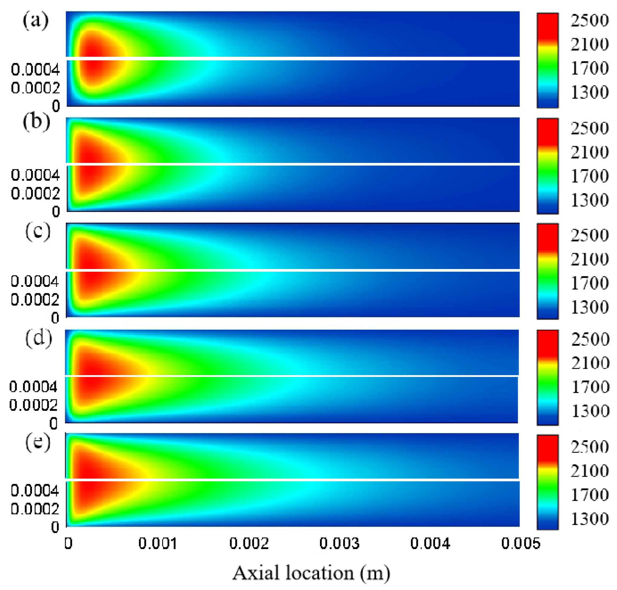
The effect of pressure on the temperature distribution in the microchannel is shown in Figure 5, where the inlet velocity is 1 m/s, and the equivalence ratio is 1.0. It can be seen that the high temperature region is minimized at a pressure of 1 atm, and as the pressure increases, the temperature inside the microchannel becomes higher. At lower pressures, the temperature at the outlet is close to the inlet temperature of 1273 K, while at higher pressures, the temperature exceeds 1300 K. This is due to the fact that as the pressure rises, there are more free-radical collisions per unit time, and the reaction is accelerated, resulting in a higher temperature of the combustion products.
Consistent with the results of Raimondeau [29], two different zones can be distinguished based on the temperature and the free-radical distribution after combustion, where the combustion zone is approximately the axial distance from 0–0.7 mm, and the rest is the burnout zone. Comparing the upper and lower figures of Figure 5a–e reveals that the active and inert wall surfaces have little effect on the overall temperature distribution in the microchannel at each pressure. The temperature of the microchannel combustion zone on the inert surface is slightly lower than that on the active surface at a pressure of 2 atm, whereas at 2.5 atm and 3 atm, the situation is just the opposite, with the temperature under the inert surface being slightly higher than that of the active surface.
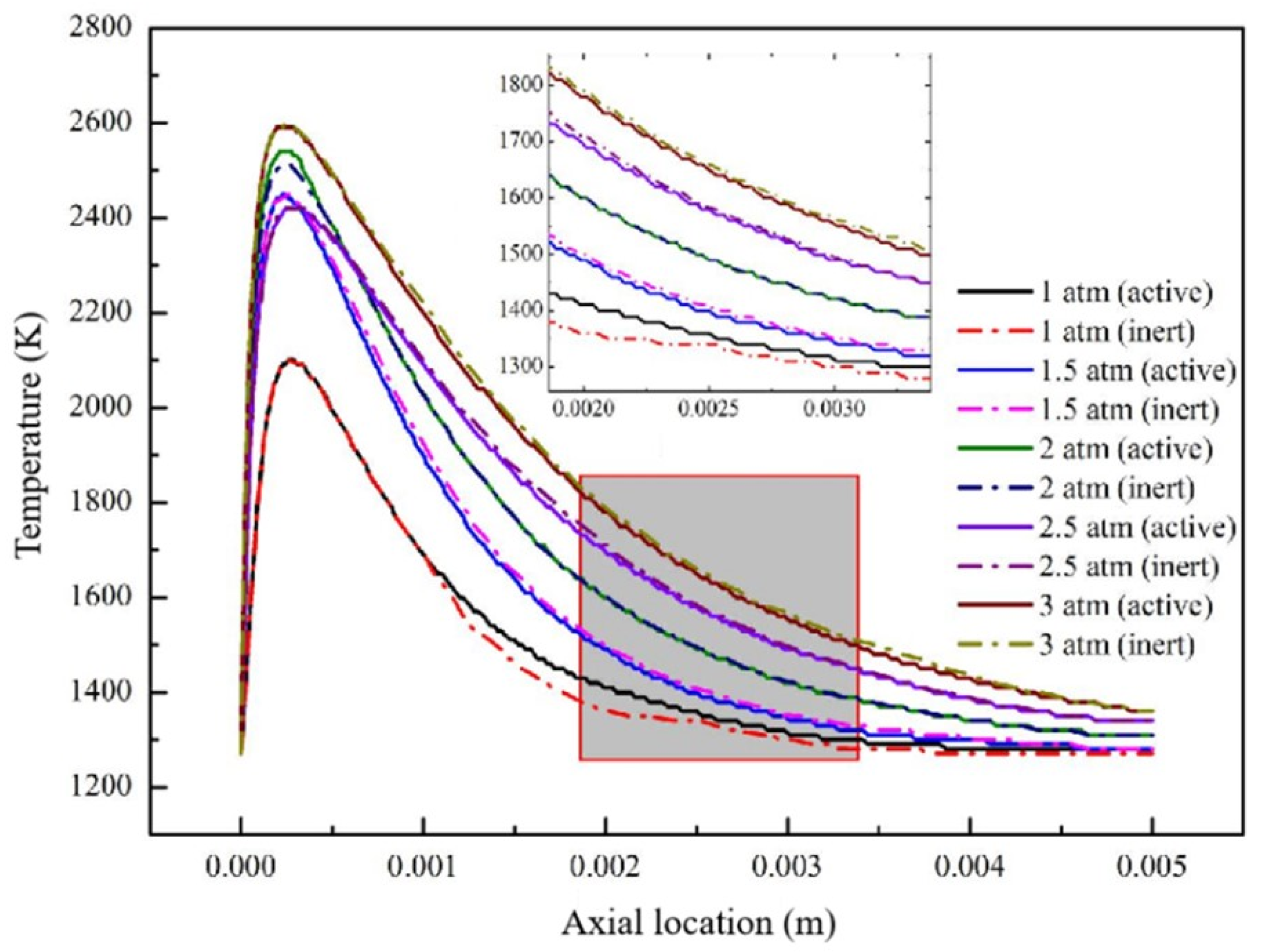
The temperature-gradient distribution on the axis of the inert and active wall surface at different pressures is very significant, as shown in Figure 6. The average and maximum temperatures on the axis at a pressure of 1 atm are the lowest, with the highest temperature occurring near an axial distance of 0.0003 m at about 2100 K. The maximum temperature under each pressure is near the axial distance of 0.0003 m, and both the average and the maximum temperatures on the axis tended to increase with increasing pressure, but the change is slow. The temperature at the outlet under each pressure is not much different and also increases with the increase of pressure.
Comparing the results of the inert and the active wall surface, it is also found that there is not much difference in the combustion zone, but the difference gradually becomes obvious in the burnout zone [56]. This is mainly due to the fact that as the reaction consumption of the reactants in the combustion zone, the concentration of the reactants left in the burnout zone decreases obviously, and the higher the pressure, the higher the molecular collision probability, which leads to the increase of the reaction rate and the higher temperature on the axis. It is also found that in the post-combustion region, the temperature is higher on the axis of the active wall at a pressure of 1 atm, while this phenomenon is reversed when the pressure is increased.
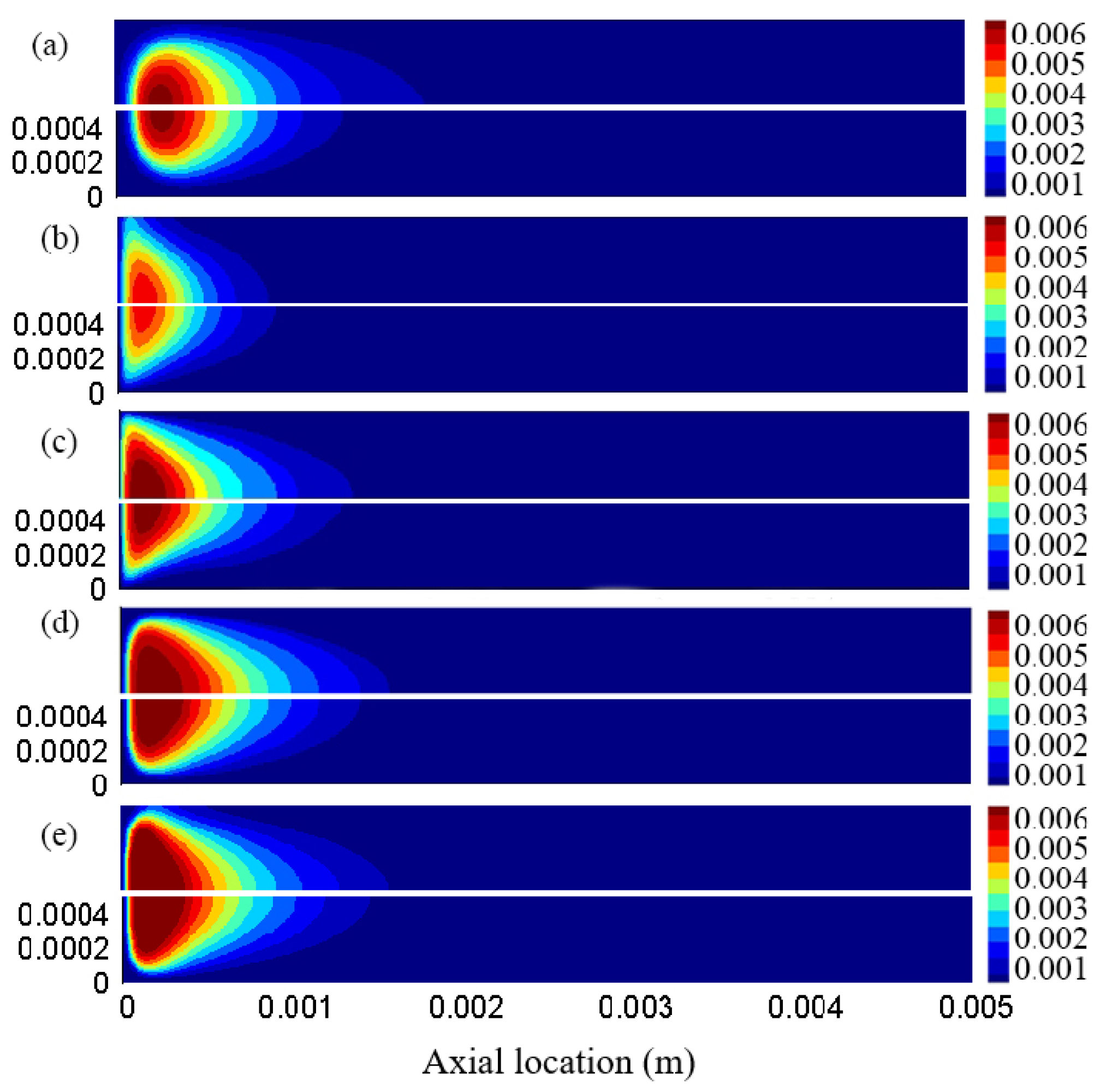
In order to explore the effects of inert and active wall surface on the distribution of OH radicals in microchannels at different pressures, an equivalence ratio of 1.0 and an inlet velocity of 1.0 m/s were chosen for the study. The combustion zone has significant axial and transverse mass fraction gradients, as shown in Figure 7. There is no significant mass fraction gradient in the burnout region due to the severe gas-phase reaction that occurs and releases heat, resulting in a sharp increase in temperature. The mass fraction of OH radicals was lowest at a pressure of 1.5 atm. It is also found that at a pressure of 1 atm, the combustion reaction occurs later than at higher pressures.
Comparison of the upper and lower pictures shows that the OH radical mass fraction in the microchannel of the inert surface is slightly larger than that of the active surface. This is mainly due to the increase in the number of OH radicals colliding with the wall as the pressure increases [28]. OH radicals are absorbed upon collision with the active wall while they bounce back into the microchannel upon collision with the inert wall for continued survival or proceed to the next reaction. Combined with Figure 5, it can be seen that the temperature distribution is consistent with the OH radical distribution. When the pressure is increased, the temperature increases along with the OH radical mass fraction. In other words, the OH radical distribution can also reflect the temperature distribution.

3.2. Effect of Different Equivalence Ratios

Equivalence ratio is an important factor affecting combustion stability and efficiency [57]. Whether oxygen is sufficient under different equivalence ratios will affect the combustion level of premixed methane combustion. The combustion state was studied and analyzed at different methane/air equivalent ratios (0.6, 0.8, 1.0, 1.2) under the microchannel pressure of 1 atm and inlet velocity of 1.0 m/s. The temperature contours of the microflame in the microchannel inert and active wall surface under different equivalence ratios are shown in Figure 8. It can be seen that the region above the inlet temperature increases with an increasing equivalence ratio, which is due to the fact that the higher the equivalence ratio, the higher the relative methane content and the more intense the combustion. However, the high temperature region above 2100 K and the maximum temperature decreases as the equivalence ratio increases. Comparison of the results for the inert and active surface reveals little difference, and the temperature distributions are basically the same.
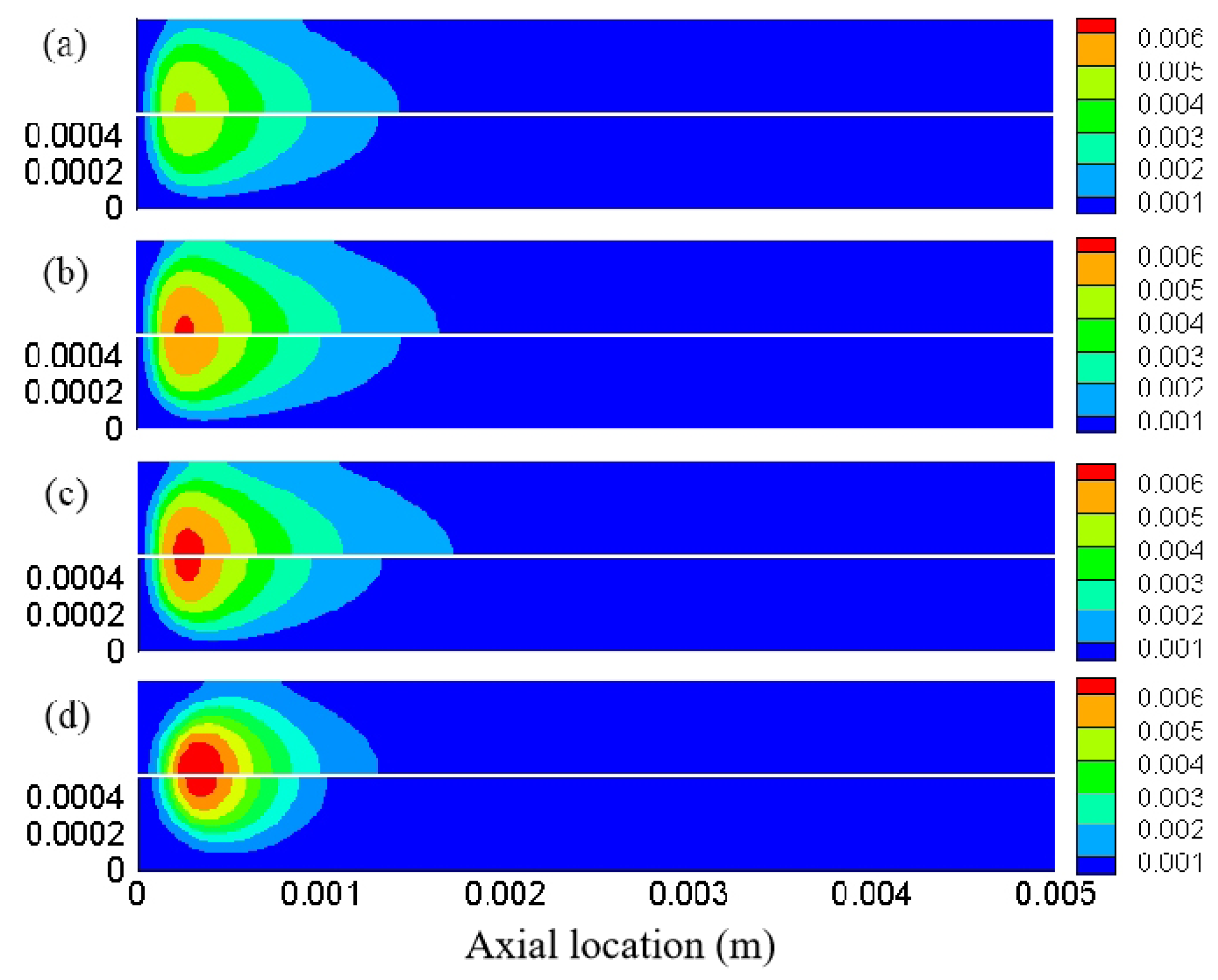
The effect of equivalence ratios on the mass fraction of OH radicals at the inert and active wall surfaces in the microchannel was investigated at an inlet velocity of 1 m/s and a pressure of 1 atm, and the results are shown in Figure 9. As the equivalence ratio increases, the OH radical mass fraction in the microchannel also increases and is always greater at the inert than at the active surface. It is also found that the content of OH radicals near the active wall in the microchannel is less, while the OH radicals on the inert surface are much less affected by the wall, so its content is higher. This is because OH radicals are absorbed on the active wall, or they reacted with the active sites on the wall, resulting in the consumption of OH free radicals, while the inert wall will not consume OH radicals. Combined with Figure 8, it can be seen that the temperature distribution is basically consistent with the OH radical distribution. After the increase of the equivalence ratio, the temperature increases along with the OH radical mass fraction.

3.3. The Effect of Different Inlet Velocity

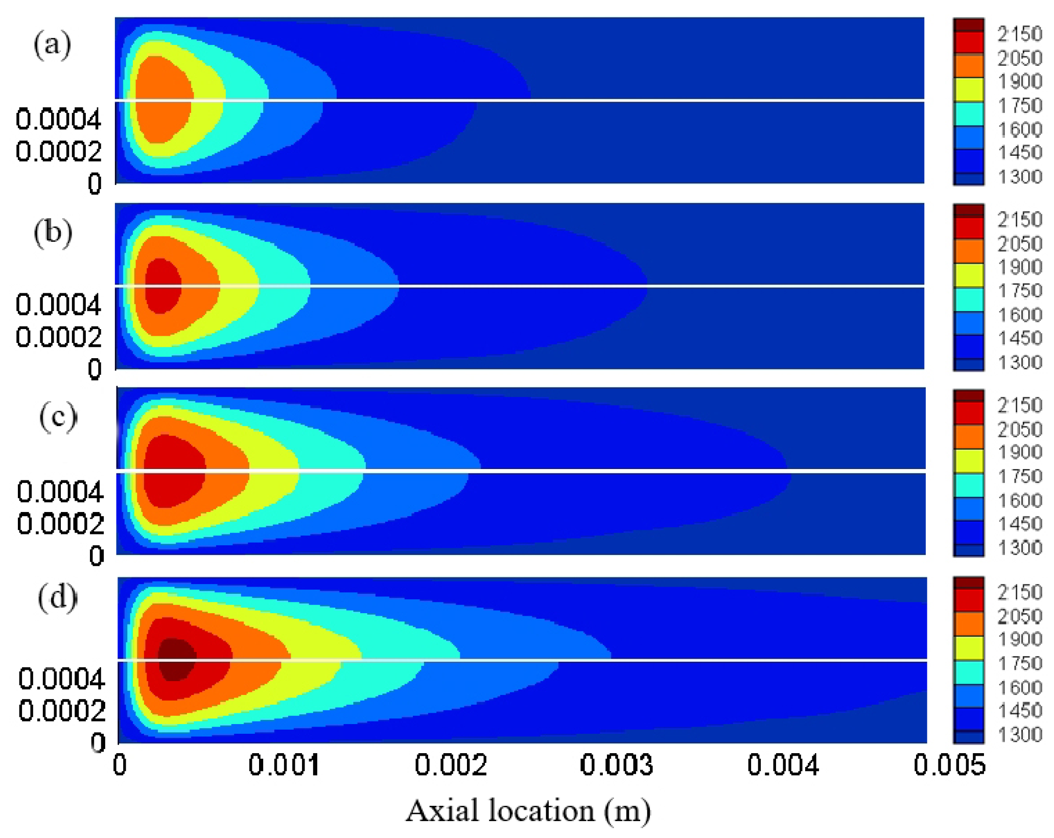
In the premixed combustion of the microchannel, the inlet velocity of the fuel determines the residence time of the fluid [58]. In order to unify the working conditions, a pressure of 1 atm and an equivalence ratio of 1.0 were taken to study the temperature distribution in inert and active wall-surface microchannels at different inlet velocities (0.5 m/s, 1.0 m/s, 1.5 m/s, 2.0 m/s). The temperature distribution contours of the microflame under different inlet velocities are shown in Figure 10. The temperature in the microchannel is lowest at an inlet velocity of 0.5 m/s, and the high temperature region above 2000 K increased with increasing inlet velocity. At a constant equivalence ratio, increasing the flow velocity results in enhanced flow disturbance and more intense combustion reactions, leading to higher temperatures in the microchannel. Comparison of the results for the inert and active surface also revealed that the temperature at the inert wall is consistently higher than in the active wall, but the temperature difference between them is not significant due to the fact that the transverse heat-transfer rate within the fluid is comparable to the heat-transfer rate at the small microchannel.
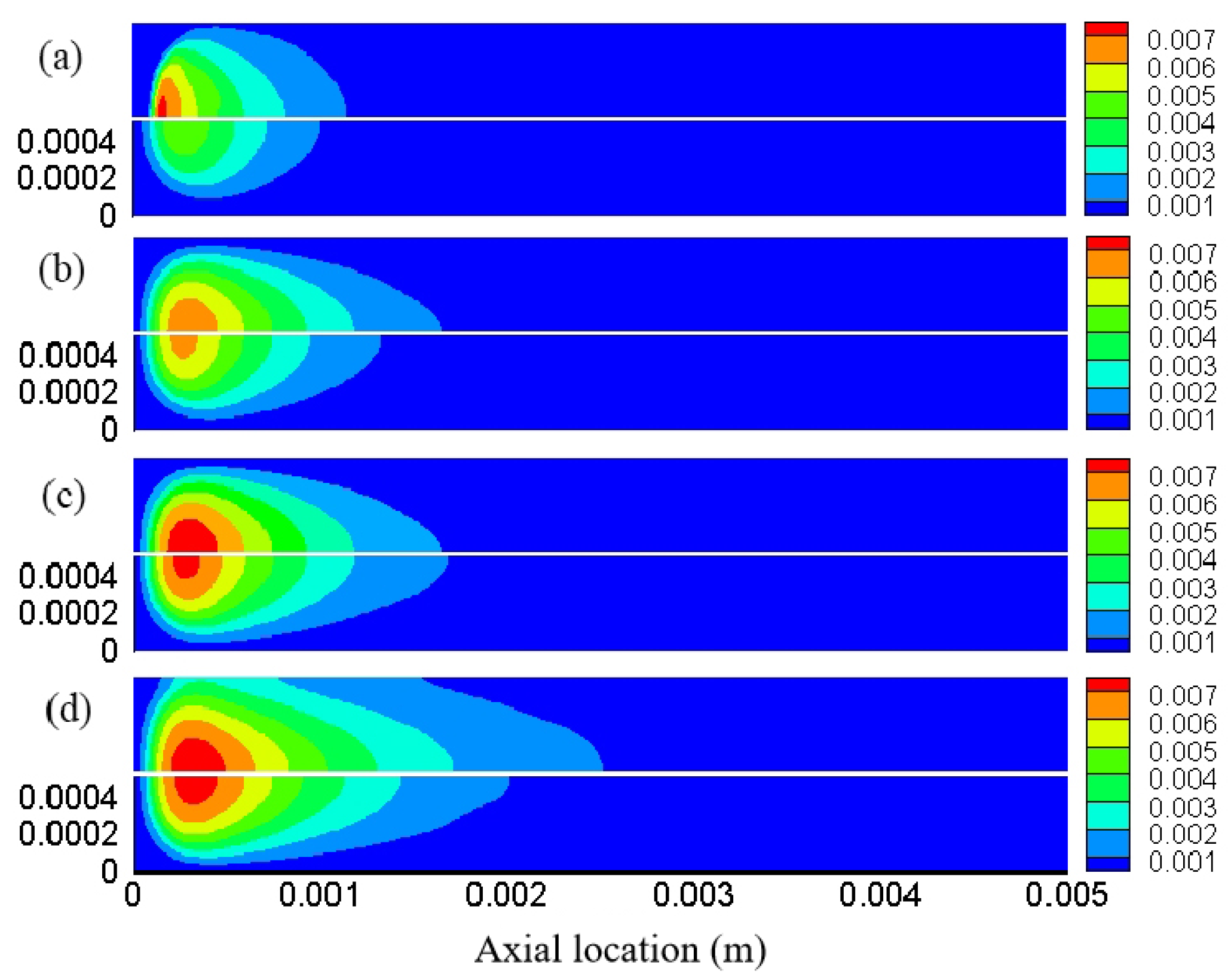
The effect of gas inlet velocity on the mass fraction of OH radicals on the inert and active wall surface of the microchannel was studied at an equivalence ratio of 1.0 and a pressure of 1 atm, as shown in Figure 11. The OH radical mass fraction increased as the inlet velocity increased simultaneously. At an inlet velocity of 0.5 m/s, a region of high OH radical mass fractions appeared at the entrance of the microchannel on the inert wall, which disappeared after continuing to increase the inlet velocity. Comparing the results of the inert and the active surface, it is also found that the mass fraction of OH radicals in the inert surface is always higher than that of the active surface, and the high-mass fraction region is becoming longer. This is mainly due to the fact that OH radicals are absorbed or involved in the reaction and thus consumed at the active surface, while OH radicals are not consumed at the inert surface but are bounced back and flow until they participate in the next reaction.

3.4. Distribution Characteristics of Other Free Radicals

The difference-temperature distribution is mainly affected by the surface reactions on the distribution of different radicals, so further discussion is necessary [59]. At an equivalence ratio of 0.8, a pressure of 1 atm, and a flow velocity of 1 m/s, the mass fraction contours of the simulation results of H, O, OH, and CH3 radicals, which are important for flame propagation and flame stability, are shown in Figure 12. For inert surfaces, the mass fractions of all radicals, especially the H, show a slight lateral gradient. Each radical exhibits a slightly higher mass fraction on the inert surface than on the active surface. This is because during the combustion reaction, free radicals will participate in the reaction at the active near-wall surface and be consumed, resulting in a reduction in mass fraction. It is also found that the distribution of OH radicals is not consistent with other radicals. The high concentration region of CH3 radicals is more advanced than other radicals; that is, the mass fraction peak comes earlier, which needs further discussion.
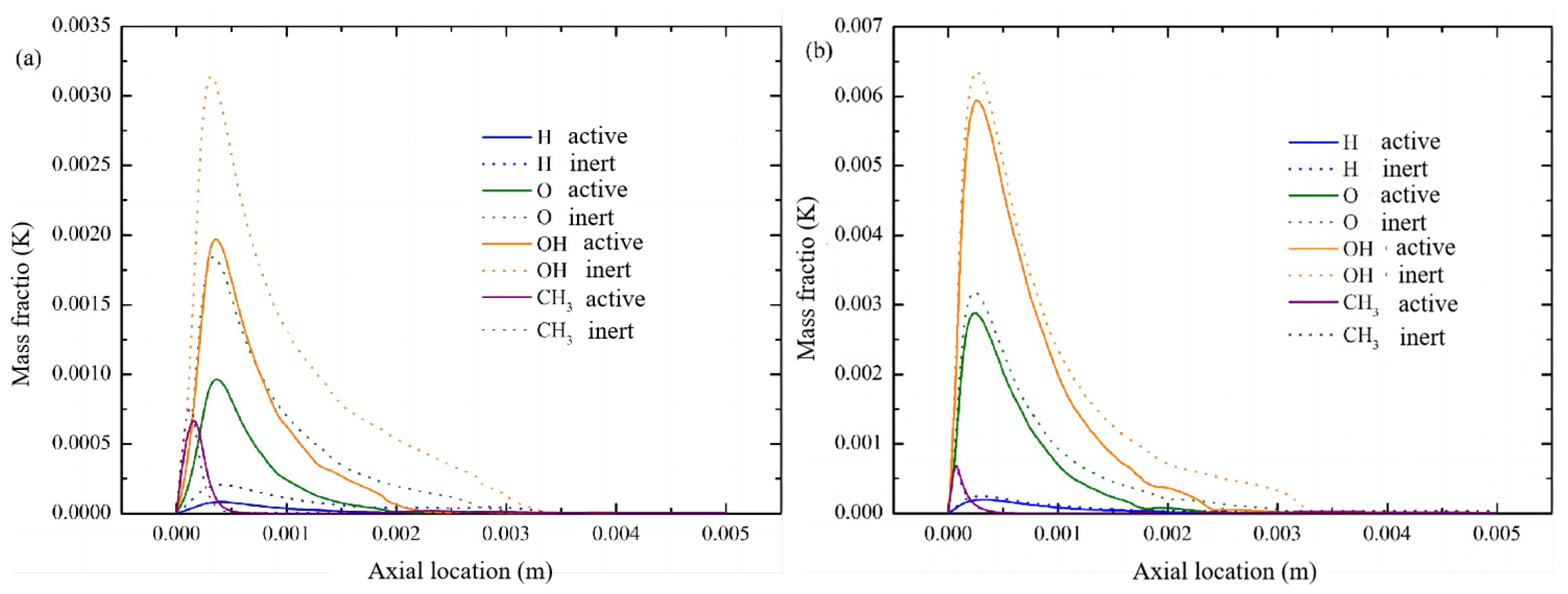
In order to understand the impact of surface reactions on free radicals, the mass fraction distribution of different radicals at the position of y = 0.1 mm near the wall and the central axis was explored under the inlet velocity of 1 m/s, an equivalence ratio of 0.8, and a pressure of 1 atm, as shown in Figure 13. In the combustion zone, the OH radical mass fraction accounts for the largest of all radicals, followed by O, and the least is H and CH3. Except for the CH3 radical, the mass fraction of the other radicals reached the peak at the same axial position. According to the premixed methane–air combustion mechanism, the dehydrogenation of methane is one of the key rate-determining steps in the entire chain-reaction process, so the mass fraction of the CH3 radical reaches the peak earliest in the axial direction. In the axial region near the wall at y = 0.1 mm, exactly opposite to the situation on the inert wall, the radical mass fraction on the active wall is significantly reduced (even higher than 60%) by surface reactions (even in the combustion region). On the contrary, at the central axis, although the mass fraction of different radicals on the active wall is slightly smaller than that on the inert surface, there is no significant difference.

4. Conclusions

Chemical quenching caused by radical deactivation has gradually attracted widespread attention, but current research on the mechanism of the influence of radical behavior near the wall on flame propagation and flame quenching is insufficient. In this paper, the influence of inlet velocity, pressure, and equivalent ratio on the combustion characteristics of methane/air premixed combustion in microchannels were studied by numerical simulation, with an emphasis on the OH radical and temperature distribution characteristics of active and inert wall surfaces. The main conclusions are as follows:
(1) The temperatures of the inlet and outlet increase as the pressure increases. At a pressure of 2 atm, the temperature of the microchannel under the inert surface is slightly higher than that of the active surface, while the opposite trend is shown at 2.5 atm and 3 atm. The temperature in the microchannel is the lowest when the inlet velocity is 0.5 m/s. As the flow rate increases, the flow disturbance increases and the combustion reaction becomes more intense, causing the temperature to increase.
(2) When the equivalence ratio increases from 0.6 to 1.2, the relative content of methane increases and the combustion becomes more intense, resulting in an increase in the region above the inlet temperature. As the equivalence ratio increases, the maximum temperature and the high-temperature region above 2100 K continue to decrease. The mass fraction of OH radicals in the microchannel also increases with the equivalence ratio, and the OH radicals on the inert surface are always larger than that of the active surface.
(3) The mass fraction peak of CH3 radicals compared to H, O, and OH radicals appears at the axial position closest to the entrance. Dehydrogenation is the starting point of methane combustion chain reaction process, so the mass fraction of the CH3 radical reaches the peak in the axial direction first, while the mass fraction of other radicals reaches the peak at about the same axial position. The temperature distribution is consistent with the OH radical distribution.

Author Contributions

Conceptualization, X.L. and Z.H.; methodology, X.L. and Q.Z.; software, X.L. and Q.Z.; validation, D.K. and S.H.; formal analysis, X.L. and S.H.; investigation, X.L. and Z.H.; resources, D.K., L.Z. and J.C.; writing—original draft preparation, X.L. and Q.Z.; writing—review and editing, X.L. and Z.H.; visualization, S.H. and L.Z.; supervision, D.K., L.Z. and J.C.; project administration, X.L., D.K. and J.C. All authors have read and agreed to the published version of the manuscript.

Funding

This research was funded by Chongqing Science and Technology Bureau (cstc2022jxjl90003), State Administration for Market Regulation (2021MK090), Science and Technology Project of Chongqing Administration for Market Regulation (CQSJKJDW2023032), and Natural Science Foundation of Chongqing (CSTB2023NSCQ-BHX0209; CSTB2022NSCQ- MSX1244).

Institutional Review Board Statement

Not applicable.

Informed Consent Statement

Not applicable.

Data Availability Statement

Data are contained within the article.

Conflicts of Interest

The authors declare no conflict of interest. The funders had no role in the design of the study; in the collection, analyses, or interpretation of data; in the writing of the manuscript; or in the decision to publish the results.

References

  1. Li, M.; Hu, T. Research status and development trend of MEMS S&A devices: A review. Def. Technol. 2021, 17, 450–456. [Google Scholar]
  2. Faudzi AA, M.; Sabzehmeidani, Y.; Suzumori, K. Application of micro-electro-mechanical systems (MEMS) as sensors: A review. J. Robot. Mechatron. 2020, 32, 281–288. [Google Scholar] [CrossRef]
  3. Bogue, R. Recent developments in MEMS sensors: A review of applications, markets and technologies. Sens. Rev. 2013, 33, 300–304. [Google Scholar] [CrossRef]
  4. Mahalik, N.P. Principle and applications of MEMS: A review. Int. J. Manuf. Technol. Manag. 2008, 13, 324–343. [Google Scholar] [CrossRef]
  5. Roos, M.M.; Winkler, A.; Nilsen, M.; Menzel, S.B.; Strehle, S. Towards green 3D-microfabrication of Bio-MEMS devices using ADEX dry film photoresists. Int. J. Precis. Eng. Manuf. Green Technol. 2022, 9, 43–57. [Google Scholar] [CrossRef]
  6. Baranski, M.; Bargiel, S.; Passilly, N.; Gorecki, C.; Jia, C.; Frömel, J.; Wiemer, M. Micro-optical design of a three-dimensional microlens scanner for vertically integrated micro-opto-electro-mechanical systems. Appl. Opt. 2015, 54, 6924–6934. [Google Scholar] [CrossRef]
  7. Wang, D.; Xie, H.; Thomas, L.; Koppal, S.J. A miniature LiDAR with a detached MEMS scanner for micro-robotics. IEEE Sens. J. 2021, 21, 21941–21946. [Google Scholar] [CrossRef]
  8. Zhang, C.; Yan, Y.; Shen, K.; Xue, Z.; You, J.; Wu, Y.; He, Z. Study on synergistic heat transfer enhancement and adaptive control behavior of baffle under sudden change of inlet velocity in a micro combustor. J. Clean. Prod. 2023, 434, 139856. [Google Scholar] [CrossRef]
  9. He, Z.; Zhang, L.; Li, X.; You, J.; Xue, Z.; Yan, Y. Heat transfer enhancement and pressure loss analysis of hydrogen-fueled microcombustor with slinky projection shape channel for micro-thermophotovoltaic system. Energy 2023, 283, 129119. [Google Scholar] [CrossRef]
  10. Nakamura, Y.; Gao, J.; Matsuoka, T. Progress in small-scale combustion. J. Therm. Sci. Technol. 2017, 12, 243–256. [Google Scholar] [CrossRef]
  11. Yu, X.; Sandhu, N.S.; Yang, Z.; Zheng, M. Suitability of energy sources for automotive application-A review. Appl. Energy 2020, 271, 115169. [Google Scholar] [CrossRef]
  12. Forsberg, C. What is the long-term demand for liquid hydrocarbon fuels and feedstocks? Appl. Energy 2023, 341, 121104. [Google Scholar] [CrossRef]
  13. Zengin, F.; Okumuş, E.; Ateş, M.N.; Tunaboylu, B. Applications and Expectations of Fuel Cells and Lithium Ion Batteries. In Digitizing Production Systems: Selected Papers from ISPR2021, Online, Turkey, 7–9 October 2021; Springer International Publishing: Berlin/Heidelberg, Germany, 2022; pp. 91–106. [Google Scholar]
  14. Aichlmayr, H.T.; Kittelson, D.B.; Zachariah, M.R. Miniature free-piston homogeneous charge compression ignition engine-compressor concept–Part I: Performance estimation and design considerations unique to small dimensions. Chem. Eng. Sci. 2015, 57, 4161–4171. [Google Scholar] [CrossRef]
  15. Kim, N.I.; Aizumi, S.; Yokomori, T.; Kato, S.; Fujimori, T.; Maruta, K. Development and scale effects of small Swiss-roll combustors. Proc. Combust. Inst. 2007, 31, 3243–3250. [Google Scholar] [CrossRef]
  16. Zuo, W.; Wang, Z.; Jiaqiang, E.; Li, Q.; Cheng, Q.; Wu, Y.; Zhou, K. Numerical investigations on the performance of a hydrogen-fueled micro planar combustor with tube outlet for thermophotovoltaic applications. Energy 2023, 263, 125957. [Google Scholar] [CrossRef]
  17. Zuo, W.; Li, D.; Jiaqiang, E.; Xia, Y.; Li, Q.; Quan, Y.; Zhang, G. Parametric study of cavity on the performance of a hydrogen-fueled micro planar combustor for thermophotovoltaic applications. Energy 2023, 263, 126028. [Google Scholar] [CrossRef]
  18. Zuo, W.; Chen, Z.; Jiaqiang, E.; Li, Q.; Zhang, G.; Huang, Y. Effects of structure parameters of tube outlet on the performance of a hydrogen-fueled micro planar combustor for thermophotovoltaic applications. Energy 2023, 266, 126434. [Google Scholar] [CrossRef]
  19. Chen, Z.; Zuo, W.; Zhou, K.; Li, Q.; Yi, Z.; Huang, Y. Numerical investigation on the performance enhancement of PEMFC with gradient sinusoidal-wave fins in cathode channel. Energy 2023, 288, 129894. [Google Scholar] [CrossRef]
  20. Yue, L.; Li, G.; He, G.; Guo, Y.; Xu, L.; Fang, W. Impacts of hydrogen to carbon ratio (H/C) on fundamental properties and supercritical cracking performance of hydrocarbon fuels. Chem. Eng. J. 2016, 283, 1216–1223. [Google Scholar] [CrossRef]
  21. Feng, Y.; Qin, J.; Zhang, S.; Bao, W.; Cao, Y.; Huang, H. Modeling and analysis of heat and mass transfers of supercritical hydrocarbon fuel with pyrolysis in mini-channel. Int. J. Heat Mass Transf. 2015, 91, 520–531. [Google Scholar] [CrossRef]
  22. Ju, Y.; Maruta, K. Microscale combustion: Technology development and fundamental research. Prog. Energy Combust. Sci. 2011, 37, 669–715. [Google Scholar] [CrossRef]
  23. You, J.; Xue, Z.; He, Z.; Yan, Y.; Zhang, Z. Hydrogel use in burn therapy, thermal management, wastewater treatment and fire fighting: A review. Environ. Chem. Lett. 2023, 21, 3273–3328. [Google Scholar] [CrossRef]
  24. Yang, X.; Li, S.; Yu, B.; Lyu, F.; Ma, X. Improving the thermophotovoltaic performance of a hydrogen-fueled planar combustor with four-corner inlets via partially inserting porous medium. Fuel 2023, 339, 126926. [Google Scholar] [CrossRef]
  25. Thapa, S.; Borquist, E.; Baniya, A.; Weiss, L. Experimental and computational investigation of a MEMS-based boiler for waste heat recovery. Energy Convers. Manag. 2015, 100, 403–413. [Google Scholar] [CrossRef]
  26. Mathew, B.; Jakub-Wood, B.; Ogbonnaya, E.; Weiss, L. Investigation of a MEMS-based capillary heat exchanger for thermal harvesting. Int. J. Heat Mass Transf. 2013, 58, 492–502. [Google Scholar] [CrossRef]
  27. Yang, M.; Li, C.; Tang, Y.; Wu, W.; Zhang, X. A collaborative resequencing approach enabled by multi-core PREA for a multi-stage automotive flow shop. Expert Syst. Appl. 2024, 237, 121825. [Google Scholar] [CrossRef]
  28. Zhang, Y.; Pan, J.; Lu, Q.; Wang, Y.; Li, J.; Quaye, E.K.; Weng, J. Numerical investigation on the self-ignition and combustion characteristics of H2/air in catalytic micro channel. Int. J. Hydrogen Energy 2022, 47, 1965–1978. [Google Scholar] [CrossRef]
  29. Raimondeau, S.; Norton, D.; Vlachos, D.G.; Masel, R.I. Modeling of high-temperature microburners. Proc. Combust. Inst. 2002, 29, 901–907. [Google Scholar] [CrossRef]
  30. Peng, Q.; Yang, W.; Jiaqiang, E.; Li, S.; Li, Z.; Xu, H.; Fu, G. Effects of propane addition and burner scale on the combustion characteristics and working performance. Appl. Energy 2021, 285, 116484. [Google Scholar] [CrossRef]
  31. Maruta, K.; Kataoka, T.; Kim, N.I.; Minaev, S.; Fursenko, R. Characteristics of combustion in a narrow channel with a temperature gradient. Proc. Combust. Inst. 2005, 30, 2429–2436. [Google Scholar] [CrossRef]
  32. Zhang, Y.; Lu, Q.; Fan, B.; Long, L.; Quaye, E.K.; Pan, J. Effect of multiple bluff bodies on hydrogen/air combustion characteristics and thermal properties in micro combustor. Int. J. Hydrogen Energy 2023, 48, 4064–4072. [Google Scholar] [CrossRef]
  33. Kamada, T.; Nakamura, H.; Tezuka, T.; Hasegawa, S.; Maruta, K. Study on combustion and ignition characteristics of natural gas components in a micro flow reactor with a controlled temperature profile. Combust. Flame 2014, 161, 37–48. [Google Scholar] [CrossRef]
  34. Jiaqiang, E.; Luo, B.; Han, D.; Chen, J.; Liao, G.; Zhang, F.; Ding, J. A comprehensive review on performance improvement of micro energy mechanical system: Heat transfer, micro combustion and energy conversion. Energy 2022, 239, 122509. [Google Scholar]
  35. Pan, J.; Zhang, C.; Pan, Z.; Wu, D.; Zhu, Y.; Lu, Q.; Zhang, Y. Investigation on the effect of bluff body ball on the combustion characteristics for methane/oxygen in micro combustor. Energy 2020, 190, 116465. [Google Scholar] [CrossRef]
  36. Okuno, T.; Nakamura, H.; Tezuka, T.; Hasegawa, S.; Maruta, K. Ultra-lean combustion characteristics of premixed methane flames in a micro flow reactor with a controlled temperature profile. Proc. Combust. Inst. 2017, 36, 4227–4233. [Google Scholar] [CrossRef]
  37. Guo, L.; Zhai, M.; Xu, S.; Shen, Q.; Dong, P.; Bai, X.S. Flame characteristics of methane/air with hydrogen addition in the micro confined combustion space. Int. J. Hydrogen Energy 2022, 47, 19319–19337. [Google Scholar] [CrossRef]
  38. Wang, Y.; Pan, J.; Wang, J.; Lu, Q.; Zhang, Y.; Quaye, E.K. Study on repetitive extinction-ignition characteristics of methane/oxygen combustion in micro tube combustor. Fuel 2023, 334, 126597. [Google Scholar] [CrossRef]
  39. Baigmohammadi, M.; Sadeghi, S.S.; Tabejamaat, S.; Zarvandi, J. Numerical study of the effects of wire insertion on CH4 (methane)/AIR pre-mixed flame in a micro combustor. Energy 2013, 54, 271–284. [Google Scholar] [CrossRef]
  40. Wang, Q.; Zhao, Y.; Wu, F.; Bai, J. Study on the combustion characteristics and ignition limits of the methane homogeneous charge compression ignition with hydrogen addition in micro-power devices. Fuel 2019, 236, 354–364. [Google Scholar] [CrossRef]
  41. Kim, K.T.; Lee, D.H.; Kwon, S. Effects of thermal and chemical surface-flame interaction on flame quenching. Combust. Flame 2006, 146, 19–28. [Google Scholar] [CrossRef]
  42. Fan, Y.; Suzuki, Y.; Kasagi, N. Experimental study of micro-scale premixed flame in quartz channels. Proc. Combust. Inst. 2009, 32, 3083–3090. [Google Scholar] [CrossRef]
  43. Fan, Y.; Suzuki, Y.; Kasagi, N. Quenching mechanism study of oscillating flame in micro channels using phase-locked OH-PLIF. Proc. Combust. Inst. 2011, 33, 3267–3273. [Google Scholar] [CrossRef]
  44. Fan, Y.; Suzuki, Y.; Kasagi, N. Flame Propagation and Quenching in Ultra-Thin Quartz Combustors. In Proceedings of the 7th International Workshop on Micro and Nanotechnology for Power Generation and Energy Conversion Applications (PowerMEMS 2007), Freiburg, Germany, 28–29 November 2007. [Google Scholar]
  45. Fan, Y.; Lin, W.; Wan, S.; Suzuki, Y. Investigation of wall chemical effect using PLIF measurement of OH radical generated by pulsed electric discharge. Combust. Flame 2018, 196, 255–264. [Google Scholar] [CrossRef]
  46. Johe, P.; Zentgraf, F.; Greifenstein, M.; Steinhausen, M.; Hasse, C.; Dreizler, A. Characterization of flow field and combustion dynamics in a novel pressurized side-wall quenching burner using high-speed PIV/OH-PLIF measurements. Int. J. Heat Fluid Flow 2022, 94, 108921. [Google Scholar] [CrossRef]
  47. Prakash, S.; Glumac, N.G.; Shankar, N.; Shannon, M.A. OH concentration profiles over alumina, quartz, and platinum surfaces using laser-induced fluorescence spectroscopy in low-pressure hydrogen/oxygen flames. Combust. Sci. Technol. 2005, 177, 793–817. [Google Scholar] [CrossRef]
  48. Davis, M.B.; Pawson, M.D.; Veser, G.; Schmidt, L.D. Methane oxidation over noble metal gauzes: An LIF study. Combust. Flame 2000, 123, 159–174. [Google Scholar] [CrossRef]
  49. Vlachos, D.G.; Schmidt, L.D.; Aris, R. Ignition and extinction of flames near surfaces: Combustion of CH4 in air. AIChE J. 1994, 40, 1005–1017. [Google Scholar] [CrossRef]
  50. Saiki, Y.; Suzuki, Y. Effect of wall surface reaction on a methane-air premixed flame in narrow channels with different wall materials. Proc. Combust. Inst. 2013, 34, 3395–3402. [Google Scholar] [CrossRef]
  51. Jens, K.N.; Studt, F.; Abild-Pedersen, F.; Bligaard, T. Fundamental Concepts in Heterogeneous Catalysis; John Wiley & Sons: Hoboken, NJ, USA, 2014. [Google Scholar]
  52. Kuo, C.H.; Ronney, P.D. Numerical modeling of non-adiabatic heat-recirculating combustors. Proc. Combust. Inst. 2007, 31, 3277–3284. [Google Scholar] [CrossRef]
  53. Chen, P.; Sun, Y.; Li, Y.; Luo, G. Experimental and LES investigation of premixed methane/air flame propagating in an obstructed chamber with two slits. J. Loss Prev. Process Ind. 2017, 49, 711–721. [Google Scholar] [CrossRef]
  54. Tingas, E.A.; Wang, Z.; Sarathy, S.M.; Im, H.G.; Goussis, D.A. Chemical kinetic insights into the ignition dynamics of n-hexane. Combust. Flame 2018, 188, 28–40. [Google Scholar] [CrossRef]
  55. Guan, L.; Tang, C.; Yang, K.; Mo, J.; Huang, Z. Experimental and kinetic study on ignition delay times of di-n-butyl ether at high temperatures. Energy Fuels 2014, 28, 5489–5496. [Google Scholar] [CrossRef]
  56. Wu, R.; Beutler, J.; Price, C.; Baxter, L.L. Biomass char particle surface area and porosity dynamics during gasification. Fuel 2020, 264, 116833. [Google Scholar] [CrossRef]
  57. Badawy, T.; Hamza, M.; Mansour, M.S.; Elbaz, A.M.; Turner, J.W.; Fayad, M.A.; Wang, C. Flame stability and equivalence ratio assessment of turbulent partially premixed flames. Fuel 2022, 326, 125107. [Google Scholar] [CrossRef]
  58. Zhang, Y.; Pan, J.; Tang, A.; Lu, Q.; Zha, Z.; Bani, S. Effects of inlet parameters on combustion characteristics of premixed CH4/Air in micro channels. J. Energy Inst. 2019, 92, 824–834. [Google Scholar] [CrossRef]
  59. Zhou, B.; Yang, S.; Jiang, X.; Cai, J.; Xu, Q.; Song, W.; Zhou, Q. The reaction of free radicals and functional groups during coal oxidation at low temperature under different oxygen concentrations. Process Saf. Environ. Prot. 2021, 150, 148–156. [Google Scholar] [CrossRef]
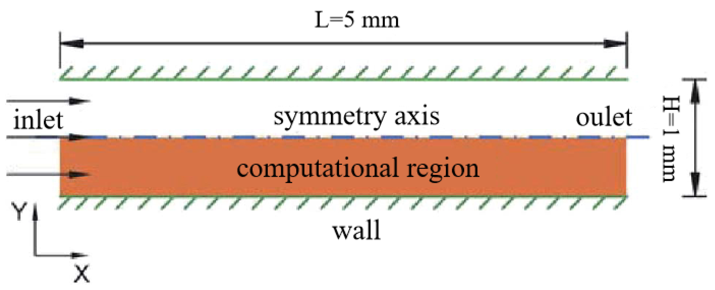
Figure 1. Physical model.
Fire 07 00071 g001
Figure 2. Grid division of microchannel section.
Fire 07 00071 g002
Figure 3. Grid independence verification.
Fire 07 00071 g003
Figure 4. Comparative analysis of simulation and experimental results.
Fire 07 00071 g004
Figure 5. The temperature contours of the micro flame with inert (upper) or active surfaces (lower) with distinct pressure, under the parameters u0 = 1 m/s, ϕ = 1.0, P = (a) 1.0, (b) 1.5, (c) 2.0, (d) 2.5, (e) 3.0 atm.
Fire 07 00071 g005
Figure 6. The centerline temperature profiles for cases with inert (upper) or active surfaces (lower) at distinct pressure, with the parameters u0 = 1 m/s, ϕ = 1.0, P = (a) 1.0, (b) 1.5, (c) 2.0, (d) 2.5, (e) 3.0 atm.
Fire 07 00071 g006
Figure 7. The mass fraction contours of OH radicals of the micro flame with inert (upper) or active surfaces (lower) at distinct pressure, with the parameters u0 = 1 m/s, ϕ = 1.0, P = (a) 1.0, (b) 1.5, (c) 2.0, (d) 2.5, (e) 3.0 atm.
Fire 07 00071 g007
Figure 8. The temperature contours of the microflame with inert (upper) or active surfaces (lower) with distinct equivalent ratio, with the parameters u0 =1 m/s, P = 1 atm, ϕ = (a) 0.6, (b) 0.8, (c) 1.0, (d) 1.2.
Fire 07 00071 g008
Figure 9. The mass fraction contours of OH radicals of the microflame with inert (upper) or active surfaces (lower) with distinct equivalent ratio, with the parameters u0 = 1 m/s, P = 1 atm; ϕ = (a) 0.6, (b) 0.8, (c) 1.0, (d) 1.2.
Fire 07 00071 g009
Figure 10. The temperature contours of the microflame with inert (upper) or active surfaces (lower) with distinct inlet velocity, with the parameters P = 1 atm, ϕ = 1.0, u0 = (a) 0.5 m/s, (b) 1.0 m/s, (c) 1.5 m/s, (d) 2.0 m/s.
Fire 07 00071 g010
Figure 11. The mass fraction contours of OH radicals of the flame with inert (upper) or active surfaces (lower) with distinct inlet velocity, with the parameters P = 1 atm, ϕ = 1.0, u0 = (a) 0.5 m/s, (b) 1.0 m/s, (c) 1.5 m/s, (d) 2.0 m/s.
Fire 07 00071 g011
Figure 12. Mass fraction contours of (a) H, (b) O, (c) OH and (d) CH3 radicals with inert (upper) or active surfaces (lower), with parameters u0 =1 m/s, P = 1 atm, ϕ = 0.8.
Fire 07 00071 g012
Figure 13. The mass fraction plots of H, O, OH, and CH3 radicals (a) near the wall and (b) at the centerline, with parameters u0 = 1 m/s, P = 1 atm, ϕ = 0.8.
Fire 07 00071 g013
Disclaimer/Publisher’s Note: The statements, opinions and data contained in all publications are solely those of the individual author(s) and contributor(s) and not of MDPI and/or the editor(s). MDPI and/or the editor(s) disclaim responsibility for any injury to people or property resulting from any ideas, methods, instructions or products referred to in the content.