
Impact of Jet Fires on Steel Structures: Application of Passive Fire Protection Materials

 ,
,  and
and
Abstract
:1. Introduction
2. Materials and Methods
2.1. Methods
2.2. Materials
2.2.1. Structural Fire Protection
2.2.2. Fire Protection Coatings (FPC)
2.2.3. Fireproof Plaster
3. Results
- -
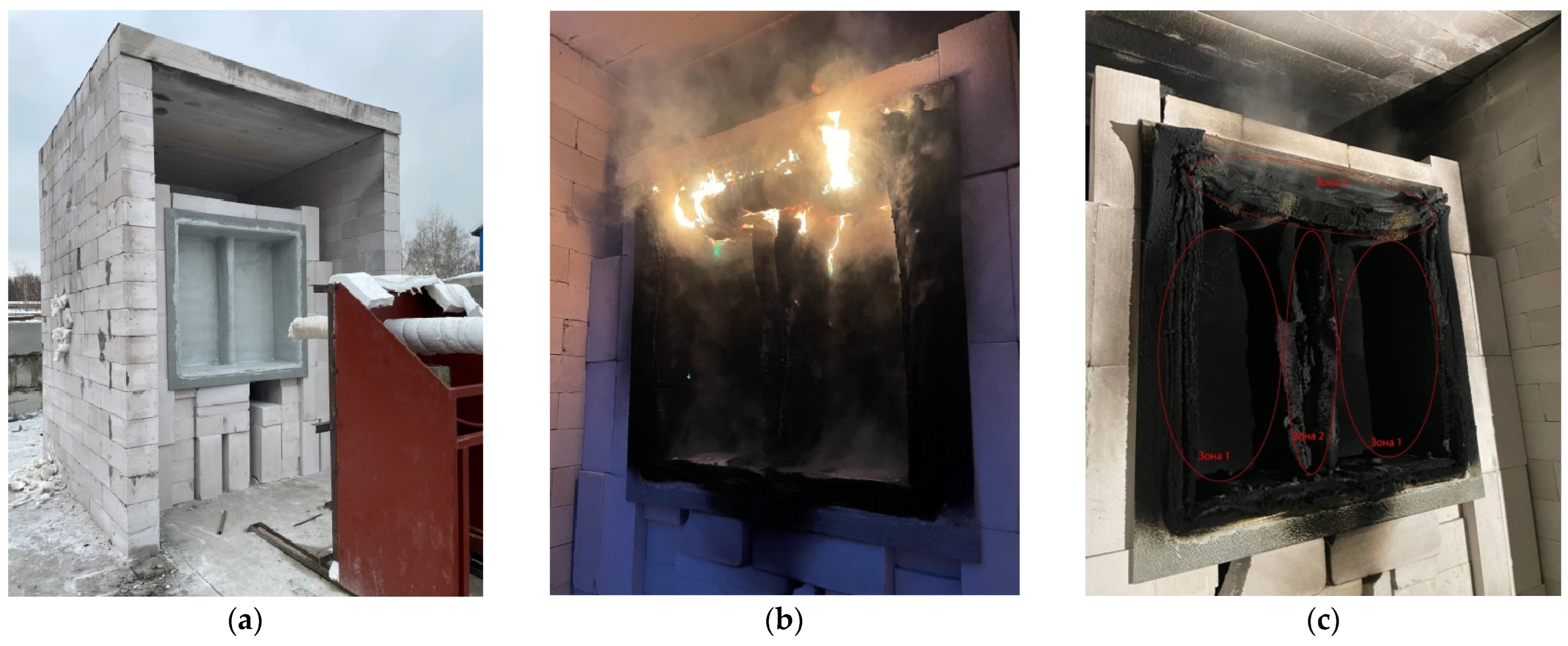
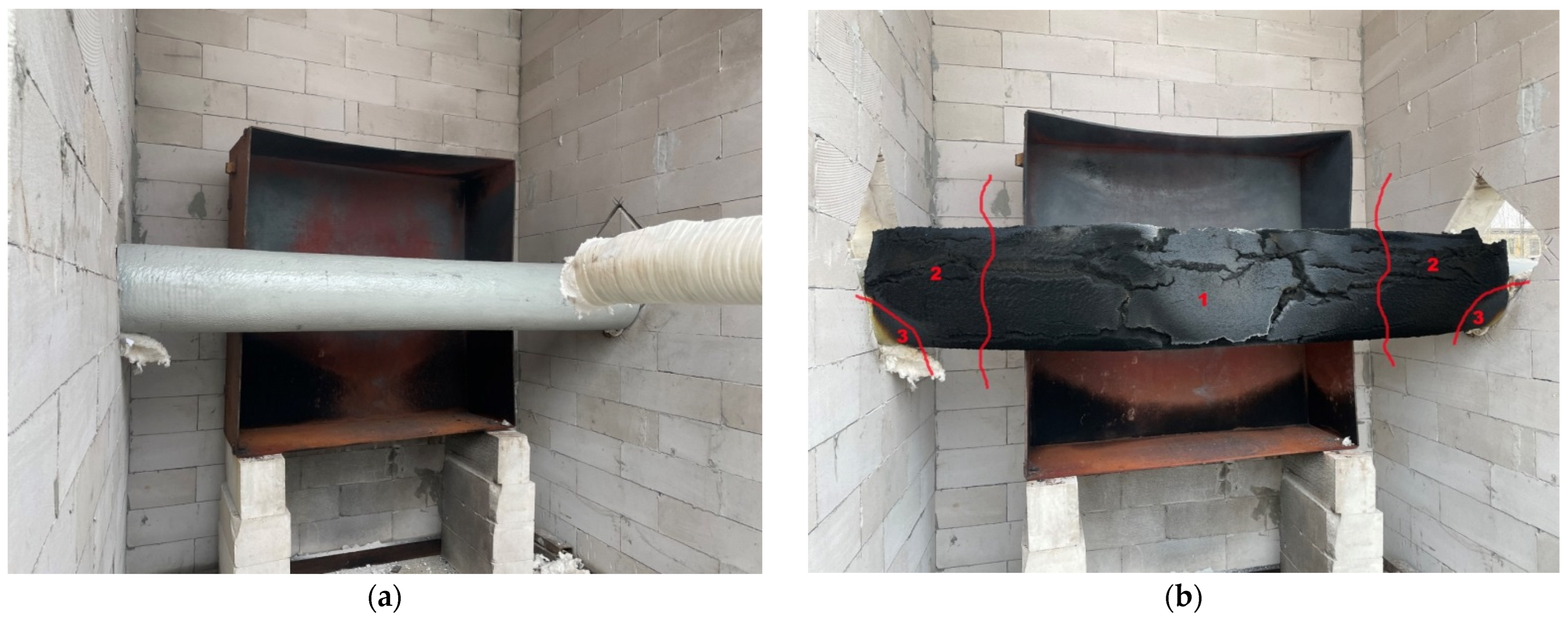
- Zone 1—reacted up to the second (outer) mesh, the flame-retardant coating is firmly in place, and the entire mesh is intact and attached;
- -
- Zone 2—has reacted up to the second (outer) mesh, the fireproofing is firmly in place, there is localized FPC failure, and the entire mesh is intact and anchored;
- -
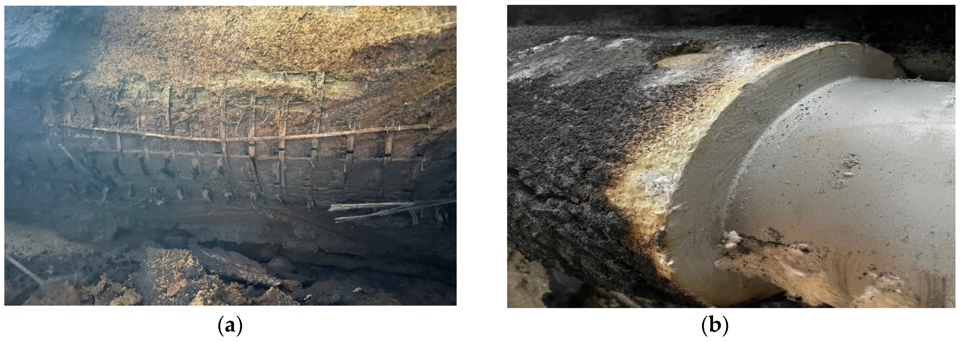
- Zone 3—bare metal insulation, poor condition of reinforcement, and the reacted FPC is easily separated.
- -
- Zone 1—the flame retardant that reacted on the second (outer) mesh is firmly retained, a localized FPC failure is observed, and the entire mesh is intact and anchored;
- -
- Zone 2—the flame retardant that reacted on the surface is firmly retained, and the entire mesh is intact and secured;
- -
- Zone 3—the unreacted/partially-reacted material is present, the unreacted-material and reinforcement are firmly retained.
4. Discussion
5. Conclusions
Author Contributions
Funding
Institutional Review Board Statement
Informed Consent Statement
Data Availability Statement
Acknowledgments
Conflicts of Interest
References
- Wang, Z.; Zhou, K.; Zhang, L.; Nie, X.; Wu, Y.; Jiang, J.; Dederichsc, A.S.; He, L. Flame extension area and temperature profile of horizontal jet fire impinging on a vertical plate. Process Saf. Environ. Protect. 2021, 147, 547–558. [Google Scholar] [CrossRef]
- Li, M.; Wang, Z.; Jiang, J.; Lin, W.; Ni, L.; Pan, Y.; Wang, G. Numerical Simulation and Consequence Analysis of Full-Scale Jet Fires for Pipelines Transporting Pure Hydrogen or Hydrogen Blended with Natural Gas. Fire 2024, 7, 180. [Google Scholar] [CrossRef]
- Karimi Dehkordi, M.; Behnam, B.; Ghasemi Pirbalouti, R. Probabilistic fire risk analysis of process pipelines. J. Loss Prev. Process Ind. 2022, 80, 104907. [Google Scholar] [CrossRef]
- Kashi, E.; Bahoosh, M. Jet fire assessment in complex environments using computational fluid dynamics. Braz. J. Chem. Eng. 2020, 37, 203–212. [Google Scholar] [CrossRef]
- Wu, Y.; Zhou, K.; Huang, M.; Zhou, M. Flame behavior of jet fire confined by the tank wall. Huagong Xuebao/CIESC J. 2021, 72, 2896–2904. [Google Scholar] [CrossRef]
- Xie, W.; Li, J.; Shi, J.; Zhang, X.; Usmani, A.S.; Chen, G. Probabilistic real-time natural gas jet fire consequence modeling of offshore platforms by hybrid deep learning approach. Mar. Pollut. Bull. 2023, 192, 115098. [Google Scholar] [CrossRef] [PubMed]
- Panaitescu, M.; Panaitescu, F.-V.; Voicu Iscupi, A.-A. FTA on ship firefighting plant. J. Mar. Technol. Environ. 2023, 42–49. [Google Scholar] [CrossRef]
- Zhou, N.; Wu, L.; Li, X.; Li, X.; Shi, J.; Cao, L. Experimental study on failure features of petrochemical pipelines under jet fire. China Saf. Sci. J. 2022, 32, 135–141. [Google Scholar] [CrossRef]
- NORSOK M-501:2022; Surface Protection and Protective Coating. NORSOK. 2022. Available online: https://www.scribd.com/document/664856568/Norsok-M-501-2022 (accessed on 7 August 2024).
- UL 1709–2022; Standard for Safety Rapid Rise Fire Tests of Protection Materials for Structural Steel. Underwriters Laboratories (UL): Northbook, IL, USA, 2022. Available online: https://www.normadoc.com/english/ul-1709-2022.html (accessed on 7 August 2024).
- API RP 2218; Fireproofing Practices in Petroleum and Petrochemical Processing Plants. API Publishing Services: Washington, DC, USA, 2013; p. 68. Available online: https://www.apiwebstore.org/standards/2218 (accessed on 7 May 2024).
- GS EP SAF 337; Total, S.A. «General Specification Safety. Passive Fire Protection: Basis of Design». TOTAL S.A. Available online: https://www.collegesidekick.com/study-docs/1530436 (accessed on 7 August 2024).
- EN 1991-1-2; Eurocode 1: Actions on Structures—Part 1–2: General Actions—Actions on Structures Exposed to Fire. CEN (European Committee for Standardization): Brussels, Belgium, 2002. Available online: https://www.phd.eng.br/wp-content/uploads/2015/12/en.1991.1.2.2002.pdf (accessed on 25 May 2024).
- Gravit, M.; Dmitriev, I.; Shcheglov, N.; Radaev, A. Oil and Gas Structures: Forecasting the Fire Resistance of Steel Structures with Fire Protection under Hydrocarbon Fire Conditions. Fire 2024, 7, 173. [Google Scholar] [CrossRef]
- Bjørge, J.S.; Metallinou, M.-M.; Kraaijeveld, A.; Log, T. Small Scale Hydrocarbon Fire Test Concept. Technologies 2017, 5, 72. [Google Scholar] [CrossRef]
- Put, F.; Lucherini, A.; Merci, B.; van Coile, R. Model uncertainty in a parametric fire curve approach: A stochastic correction factor for the compartment fire load density. Fire Saf. J. 2024, 144, 104113. [Google Scholar] [CrossRef]
- Bradley, I.; Willoughby, D.; Royle, M. A review of the applicability of the jet fire resistance test of passive fire protection materials to a range of release scenarios. Process Saf. Environ. Prot. 2019, 122, 185–191. [Google Scholar] [CrossRef]
- ASTM E 1529-14A; Standard Test Methods for Determining Effects of Large Hydrocarbon Pool Fires on Structural Members and Assemblies. ASTM International: West Conshohocken, PA, USA, 2014.
- Guidelines for Vapor Cloud Explosion, Pressure Vessel Burst, BLEVE, and Flash Fire Hazards, 2nd ed.; John Wiley & Sons, Inc.: Hoboken, NJ, USA, 2010.
- Mikalsen, R.F.; Glansberg, K.; Wormdahl, E.; Stølen, R. Jet fires and cryogenic spills: How to document extreme industrial incidents. In Proceedings of the Sixth Magdeburg Fire and Explosion Days Conference Proceedings, Magdeburg, Germany, 25–26 March 2019; pp. 1–6. [Google Scholar]
- Bogdanova, V.V.; Kobets, O.I.; Buraya, O.N.; Ustinov, A.A.; Zybina, O.A. Intumescent compounds for fireproofing of polymer pipelines. Mag. Civ. Eng. 2022, 116, 11607. [Google Scholar]
- Lucherini, A.; de Silva, D. Modelling intumescent coatings for the fire protection of structural systems: A review. J. Struct. Fire Eng. 2024; ahead-of-print. [Google Scholar] [CrossRef]
- Yew, M.C.; Yew, M.K.; Yuen, R.K.K. Experimental Analysis of Lightweight Fire-Rated Board on Fire Resistance, Mechanical, and Acoustic Properties. Fire 2023, 6, 221. [Google Scholar] [CrossRef]
- Garg, K.; Singh, S.; Rokade, M.; Singh, S. The Behavior of Passive Fire Protection Materials Used for Fire Protection of Steel Structures in Standard, Hydrocarbon, and Jet Fire Exposure. Fire Technol. 2023, 59, 2517–2541. [Google Scholar] [CrossRef]
- Tamás-Bényei, P.; Sántha, P. Potential applications of basalt fibre composites in thermal shielding. J. Therm. Anal. Calorim. 2023, 148, 271–279. [Google Scholar] [CrossRef]
- ISO 22899-1:2021; Determination of the Resistance to Jet Fires of Passive Fire Protection Materials Part 1: General Requirements. International Organization for Standardization: Geneva, Switzerland, 2021.
- ISO/TR 22899-2-2013; Determination of the Resistance to Jet Fires of Passive Fire Protection Part 2: Guidance on Classification and Implementation Methods. International Organization for Standardization: Geneva, Switzerland, 2013.
- ISO/DIS 22899-3; Determination of the Resistance to Jet Fires of Passive Fire Protection Materials—Part 3: Extended Test Requirements. Available online: https://www.iso.org/obp/ui/en/#iso:std:iso:22899:-3:dis:ed-1:v1:en (accessed on 7 August 2024).
- Rules for the Classification and Construction of Fixed Offshore Platforms nd no. 2-020201-027-e Rule Change. Notice Enters into force: 01.07.2024. © Russian Maritime Register of Shipping. 2024. Available online: https://lk.rs-class.org/regbook/getDocument2?type=rc_eng&d=24-80396 (accessed on 7 August 2024).
- GB 14907-2018; Fire resistive coating for steel structure. State Administration of Markets and China National Standardization Administration: Beijing, China, 2018.
- National Standard of Russian Federation GOST 53295-2009 Fire Retardant Compositions for Steel Constructions. General Requirement. Method for Determining Fire Retardant Efficiency. Available online: https://meganorm.ru/Data2/1/4293830/4293830765.htm (accessed on 7 May 2024).
- Charcoat. Jet Fire Coating. Available online: https://www.charcoat.com/jet-fire-coating (accessed on 14 March 2024).
- Pat. PCTEP2013065775 European. High Heat Resistant Composition DEOGON/ M.S. DEOGON, M. Singh. International Publication. Number WO 2014/019947 Al. Available online: https://patentscope.wipo.int/search/en/detail.jsf?docId=WO2014019947&_cid=P11-LZL4HZ-03296-1/ (accessed on 7 August 2024).
- Industrial Coatings Ltd. Jotun Jotachar JF750. Available online: https://industrialcoatingsltd.com/products/jotun-jotachar-jf750 (accessed on 14 March 2024).
- International Chartek 1709. Passive Fire Protection-Epoxy Intumescent. Available online: https://www.international-pc.com/en/products/chartek-1709?page=1#tds/ (accessed on 14 March 2024).
- GOST 8239-89; Hot-Rolled Steel Flange Beams; Rolling products. Publishing House of Standards: Moscow, Russia, 1989.
- Technical Specification of «Ignis-Mat». Available online: https://prozask.ru/f/ignis-mat_sv-opisanie.pdf (accessed on 7 August 2024).
- Technical Specification of Fire Barrier «Promizol-DSh Proplate». Available online: http://tdpromizol.com/ (accessed on 7 August 2024).
- Technical Specification of the «Faire-Panel». Available online: https://prozask.ru/prozask-fayerpanel (accessed on 7 August 2024).
- Gravit, M.; Shabunina, D.; Shcheglov, N. Thermal Characteristics of Epoxy Fire-Retardant Coatings under Different Fire Regimes. Fire 2023, 6, 420. [Google Scholar] [CrossRef]
- ASTM D 3359-22; Standard Test Methods for Rating Adhesion by Tape Test. American Society for Testing and Materials: West Conshohocken, PA, USA, 2022.
- GOST 19007-23; Paintwork materials; Method for determination of drying tine and degree. Institute of Standardization: Moscow, Russia, 2023.


| № | Name of Indicator | Value |
|---|---|---|
| 1 | Appearance of the plate: (a) front side; (b) back side | (a) smooth, colored; (b) polished |
| 2 | Thermal conductivity, W/m·K | 0.35 (±10%) |
| 3 | Resistance to vapor permeability, % | 60 |
| 4 | Tensile strength at bending, not less, MPa | 5.4 |
| 5 | Board density, kg/m3 | 1100–1200 |
| 6 | Fire resistance, REI (depends on the number of boards), min | 240 |
| № | Name of Indicator | Value |
|---|---|---|
| 1 | Apparent density, kg/m3 | 128 |
| 2 | Chemical composition, %: CAO, SiO2 and others, not more | 68 |
| 3 | Relative weight change during calcination, %, not more than | 1.0 |
| 4 | Tensile strength, MPa, not less than | 0.050 |
| 5 | Mass fraction of moisture, not more, % | 1.0 |
| 6 | Mass fraction of inclusions larger than 0.5 mm, %, not more than | 3.0 |
| № | Technical Specifications | Value |
|---|---|---|
| 1 | Color and appearance of the coating | Gray |
| 2 | Adhesion [41], rating, not less than | 4A |
| 3 | Composition density, kg/m3 | 1.22–1.27 |
| 4 | Stability after mixing at T = (20 ± 2) °C, h, at least | 1 |
| 5 | Theoretical consumption for one layer coating thickness of 1000 microns, kg/m2 | 1.2 |
| 6 | Drying time to degree 3 [42] (T = (20 ± 2) °C and relative humidity (65 ± 5)%, not more than | 12 ч |
| № | Types of Samples | Internal Configuration Tests | External Configuration Tests |
|---|---|---|---|
| 1 | Boards and mats system | - | Sample 1 |
| 2 | FPC-1 | Sample 2 | - |
| 3, 4 | FPC-2 | Sample 3 | Sample 4 |
| 5 | Plaster | Sample 5 | - |
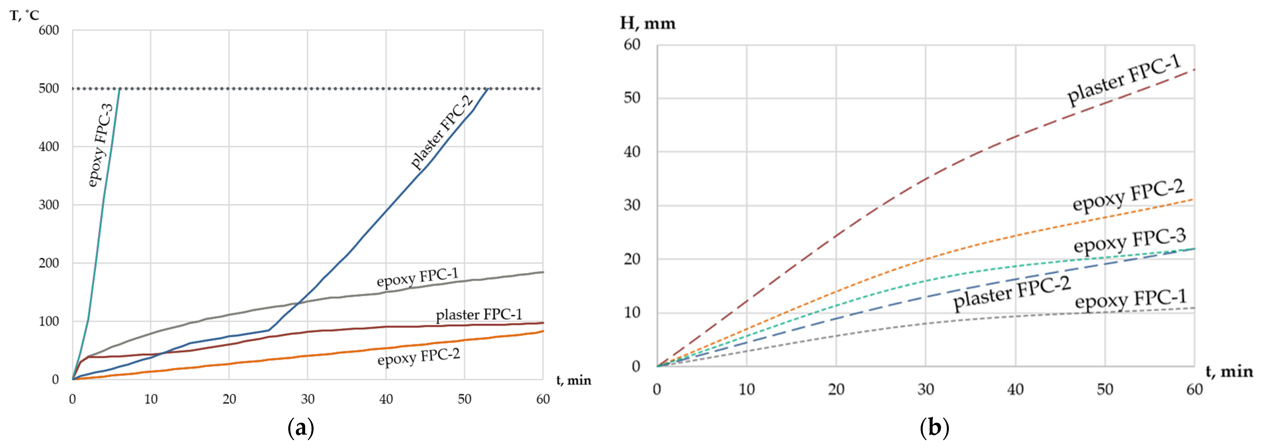
| № | Types of Samples | Configuration Tests | H, mm | T (Unheated Surface), °C | |
|---|---|---|---|---|---|
| Internal | External | ||||
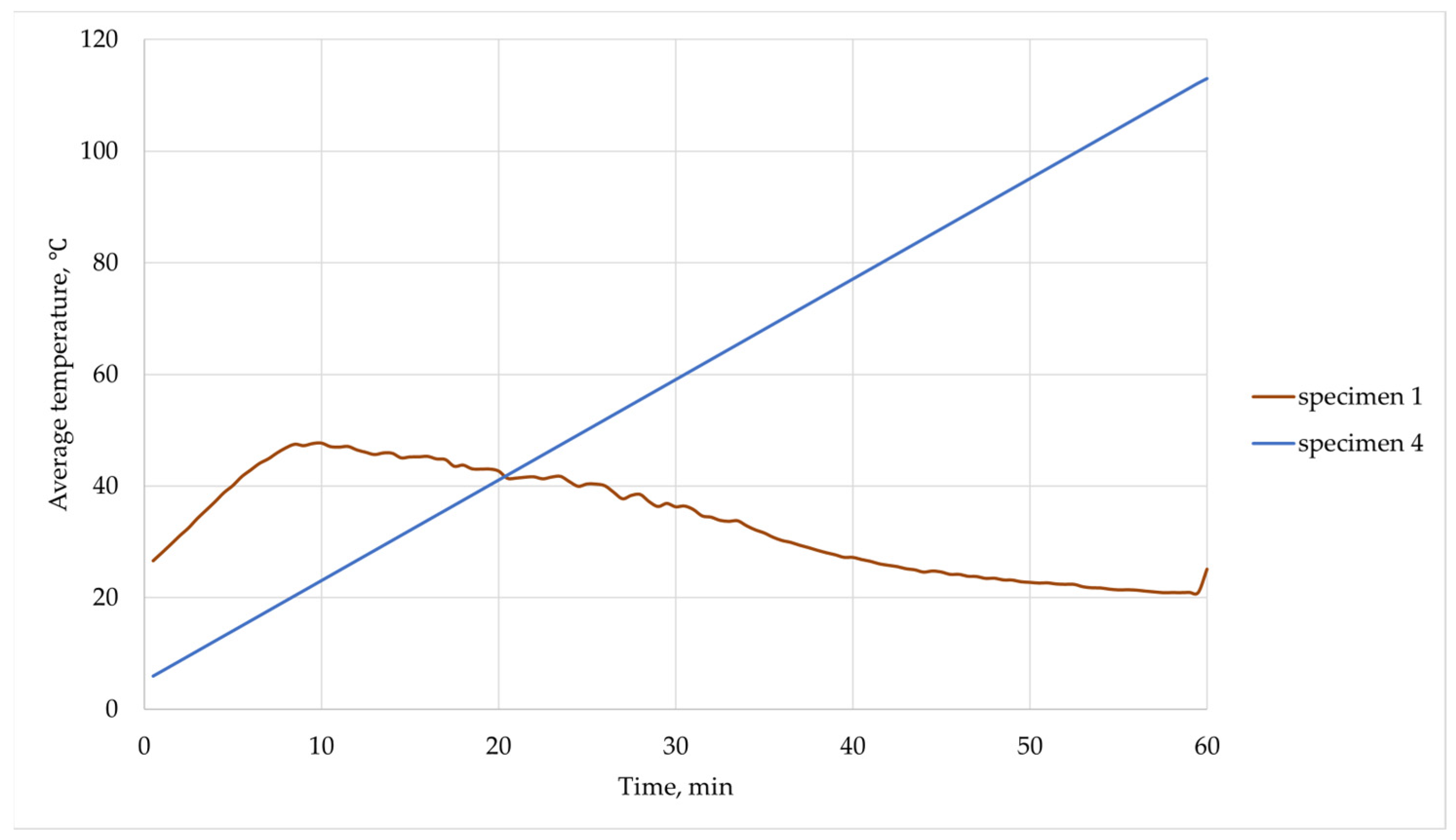
| 1 | Boards and mats system | - | Sample 1 | 25 + 50 | 47.73 |
| 2 | FPC-1 | Sample 2 | - | 10.9 | 184.84 |
| 3 | FPC-2 | Sample 3 | - | 31.2 | 82.00 |
| 4 | FPC-2 | - | Sample 4 | 31.8 | 113.00 |
| 5 | Plaster FPC-1 | Sample 5 | - | 55.4 | 97.00 |
| 6 [24] | organic material (FPC-3) | Sample 6 | 22.0 | 7.50 | |
| 7 [24] | inorganic material (Plaster FPC-2) | Sample 7 | 22.0 | 55.0 | |
Disclaimer/Publisher’s Note: The statements, opinions and data contained in all publications are solely those of the individual author(s) and contributor(s) and not of MDPI and/or the editor(s). MDPI and/or the editor(s) disclaim responsibility for any injury to people or property resulting from any ideas, methods, instructions or products referred to in the content. |
© 2024 by the authors. Licensee MDPI, Basel, Switzerland. This article is an open access article distributed under the terms and conditions of the Creative Commons Attribution (CC BY) license (https://creativecommons.org/licenses/by/4.0/).
Share and Cite
Gravit, M.; Korolchenko, D.; Nedviga, E.; Portnov, F.; Diachenko, S. Impact of Jet Fires on Steel Structures: Application of Passive Fire Protection Materials. Fire 2024, 7, 281. https://doi.org/10.3390/fire7080281
Gravit M, Korolchenko D, Nedviga E, Portnov F, Diachenko S. Impact of Jet Fires on Steel Structures: Application of Passive Fire Protection Materials. Fire. 2024; 7(8):281. https://doi.org/10.3390/fire7080281
Chicago/Turabian StyleGravit, Marina, Dmitry Korolchenko, Ekaterina Nedviga, Fedor Portnov, and Semen Diachenko. 2024. "Impact of Jet Fires on Steel Structures: Application of Passive Fire Protection Materials" Fire 7, no. 8: 281. https://doi.org/10.3390/fire7080281