Technical Note

Fire Resistance in Screwed and Hollow Core Wooden Elements Filled with Insulating Material

ISEP, Instituto Politécnico do Porto, R. Dr. António Bernardino de Almeida, 4249-015 Porto, Portugal
*
Author to whom correspondence should be addressed.
Fire 2024, 7(8), 288; https://doi.org/10.3390/fire7080288
Submission received: 3 July 2024 / Revised: 12 August 2024 / Accepted: 14 August 2024 / Published: 17 August 2024

Abstract

:
This study looks at wall partition panels with hollow core wood elements and gypsum board as protection in fire conditions. In addition to our previous research, this study on wall partitions considers the effect of steel screws in the assembly of the elements, as well as the filling of the cavity with insulating material. The goal of this work is to calculate the fire resistance time and compare the results using different numerical models. The discussion of the results analyzes the effect of steel screws and the introduction of insulating material inside the cavities. The steel screws are verified with and without threads. The numerical models are based on the finite element method, using thermal and transient analysis with nonlinear materials. The thermal insulation criterion for measuring fire resistance is referenced by the EN 1363-1:2020 standard. The steel screws allow more heat to be concentrated and, therefore, distribute it throughout the wooden wall partition members. Based on the results obtained, the use of steel screws reduces fire resistance by 71.75 min, regardless of whether the wall partition is filled with or without insulating material.

1. Introduction

Several studies have shown the advantages of CO2 in replacing conventional building materials with wooden elements, as reported by [1]. Many studies highlight the CO2 benefits of wood material. In addition, the research in [1] investigates the economic and emission impacts of wood elements within the context of climate policy.
In recent decades, there has been a rapid and increasing development of wood products for construction. As mentioned in [2], renewable technologies, reduction in environmental impacts, low-carbon materials, and technologies in construction have reinforced the main goals in several countries. According to some reports, in Europe, cross-laminated timber, laminated veneer lumber, glued laminated wood, and wood fiber insulation boards have annual growth rates of between 2.5% and 15% [1,3]. Wall partition panels are made of these materials and are more than physical barriers; they represent attractive aesthetics, acoustic advantages, and easy functionality for use in civil construction. These constructive panels are non-load bearing and are used to divide commercial, residential, industrial, and specialized spaces. They do not support any weight of the structure above them, but there are alternatives used to separate interiors temporarily or permanently. Other popular materials that are constructed are plasterboard and concrete blocks. However, when constructing wood materials, the problem is their combustible nature in fire situations.
Regarding fire situations, this study reviews published works to examine wood behavior when exposed to accidents, such as experimental and numerical tests, with an emphasis on calculating the charring rate, load bearing capacity, and fire resistance [4,5].
The key motivation of this work is to build upon previous research [6,7] and continue to investigate fire resistance in typical wall partition panels, where application in civil construction is considerable.
Standards relating to fire safety are used to ensure the level of safety [8,9,10,11,12] and can be used in the design of related components exposed to fire. Fire resistance will be calculated using the numerical model concerning the thermal insulation criterion, defined by standards EN 1363-1:2020 and EN 1364-1:2015 [8,9].
In the construction of wall partitions, cavities in wall partitions filled with insulation material are the best choice. According to some of the literature, the important properties of insulating materials are related to their efficiency and relevance for application [6,7]. Energy conservation in the construction sector has become extremely important, where the insulation material plays a significant role in ensuring that an environment is energy-efficient and comfortable [13,14]. However, in all these materials, the melting point must be considered a requirement. Greater thermal protection is the most economical way to construct buildings with lower energy expenditure and adequate thermal comfort conditions [14]. In general, the thermal conductivity of insulated materials is lower than that of other materials, leading to low heat transfer through the other parts involved [13,15,16,17].
In this work, fiberglass will be used to fill a hollow wall partition. Fiberglass is a thermal insulation material that can be used as a building thermal insulation material when it is produced in rigid board form [15]. Fiberglass board has many benefits, such as lower density and thermal conductivity, water vapor resistance, high sound absorption, and flame retardance [15]. For this reason, the fiberglass board has a perspective to be a suggestive thermal insulation material for the interior building envelope. However, the insulation performance of glass fiberboard is far away from being ideal. This is because its thermal conductivity is not constant and is influenced by its internal structure. Consequently, it is necessary to conduct tests on the thermal insulation properties of this material for use in interior buildings. However, fiberglass can withstand high temperatures and is fire-resistant.
Furthermore, steel elements are used to be fixed to any wall partition system. In fire situations, these steel elements do not prevent the passage of fire. Steel materials melt at around 1370 °C, which means they do not lose their structural integrity at the temperatures required for fire testing. However, the neighbouring wooden elements of steel fasteners become charred, leading to the loss of integrity of the wall partition system. Steel fasteners are thus critical in keeping gypsum board attached to a wall partition. Therefore, their influence on fire situations needs to be investigated.
The present study aims to determine the fire resistance of wall partition models filled with insulation material, such as fiberglass, compared with that of the same models without any internal insulation. We propose the application of our previously developed research, experimentally validated by another author [18], as referred to in [6,7], and to now investigate, in conjunction with this, the influence of steel screws on attached elements (gypsum board and wall elements) of a wall partition. The screw elements were modelled with or without thread through their length. Another objective of this research is to confirm the effects of the insulating material inside the hollow wood cavities in these types of construction models. This study has great application prospects for general engineering and civil construction practice.

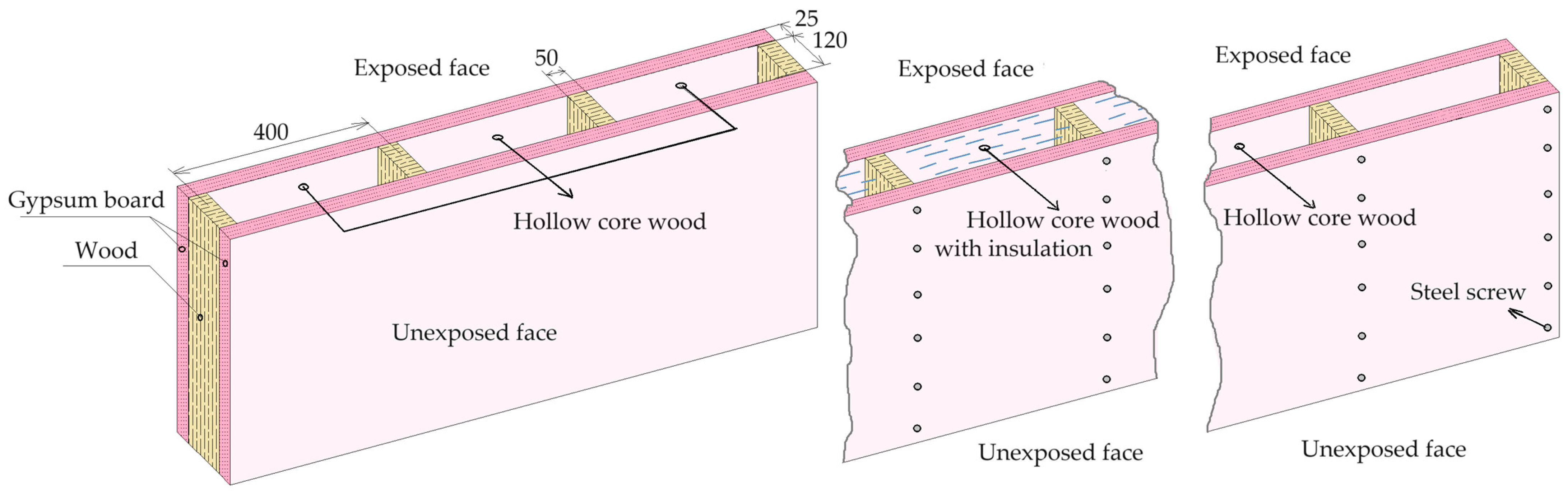
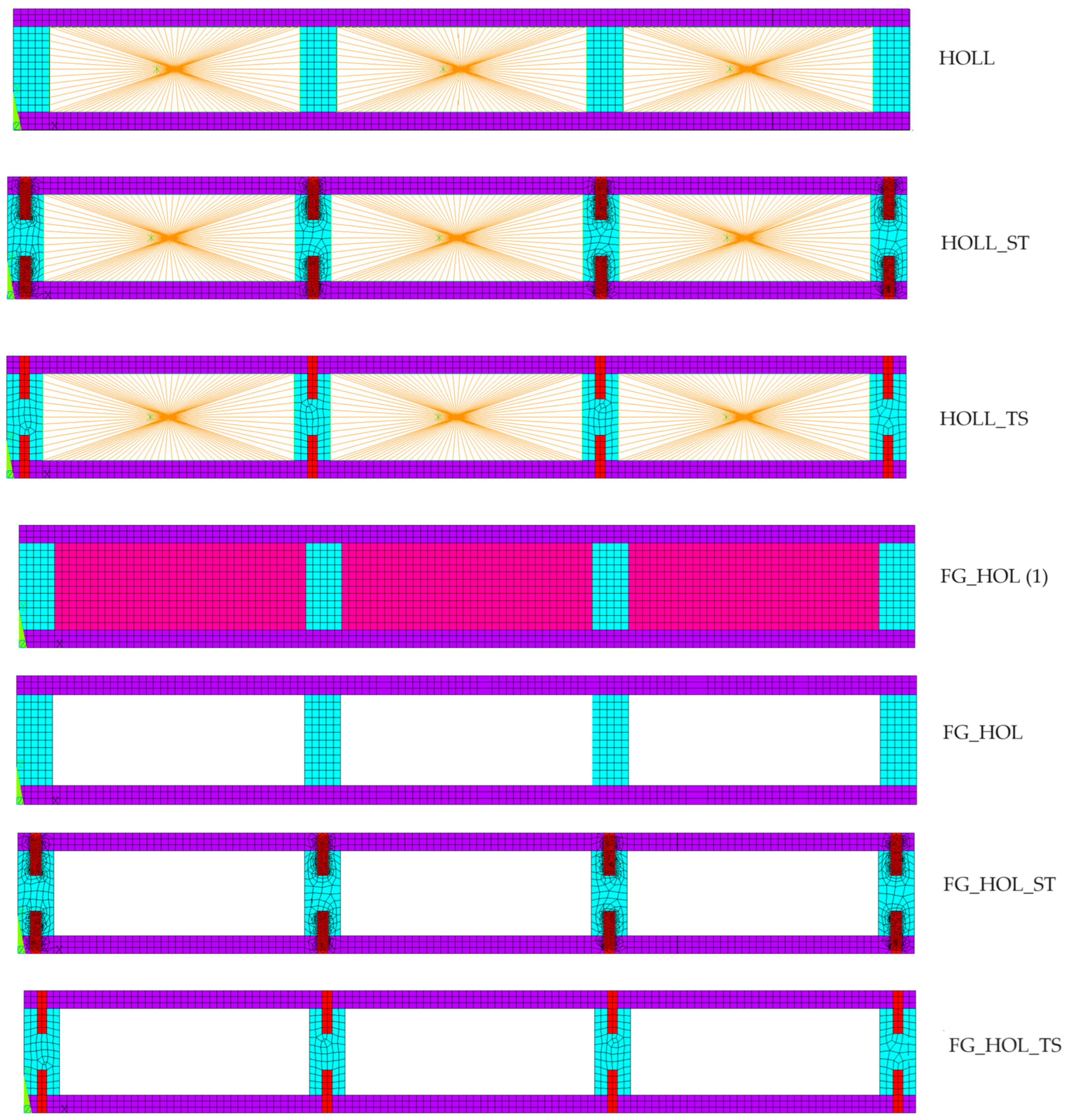
2. Wall Partition Model

According to the building construction, six different models will be considered, as presented in Table 1. The six models are representative of the combination of the used materials. Three models only represent the hollow cavities without any insulation (HOLL, HOLL_ST, HOLL_TS), and the other three are filled with fiberglass material (FG_HOL, FG_HOL_ST, FG_HOL_TS). In the models (designations HOLL and FG_HOL), the effect of steel screws was not considered. In the other models, steel screws were included with or without thread (ST or TS, respectively).
According to the building construction, six different models will be considered with the configuration shown in Figure 1.
Considering the geometry of the constructive element, a cross-section in the two-dimensional (2D) plane will be used for analysis. Figure 2 represents the typical 2D wall partition in this study as a constructive element to be used in the ANSYS® 20222 R2 program [19].
This constructive element with three cavities is designed by columns in wood GL32H [6,7], protected by gypsum board type F on each side [20]. One side was exposed to fire and the other was unexposed. The main dimensions [H = 120 mm, W = 50 mm, Tg = 25 mm, and D = 400 mm] are the distance between the wood centers, D, the height of the wood columns, H, the width of the wood column, W, and the thickness of the gypsum board, Tg. The geometric dimensions were chosen because some manufacturers and researchers have suggested these values [16,21,22]. The screw elements had a length of L = 70 mm and a diameter of Md = 16 mm.

3. Thermal and Transient Analysis

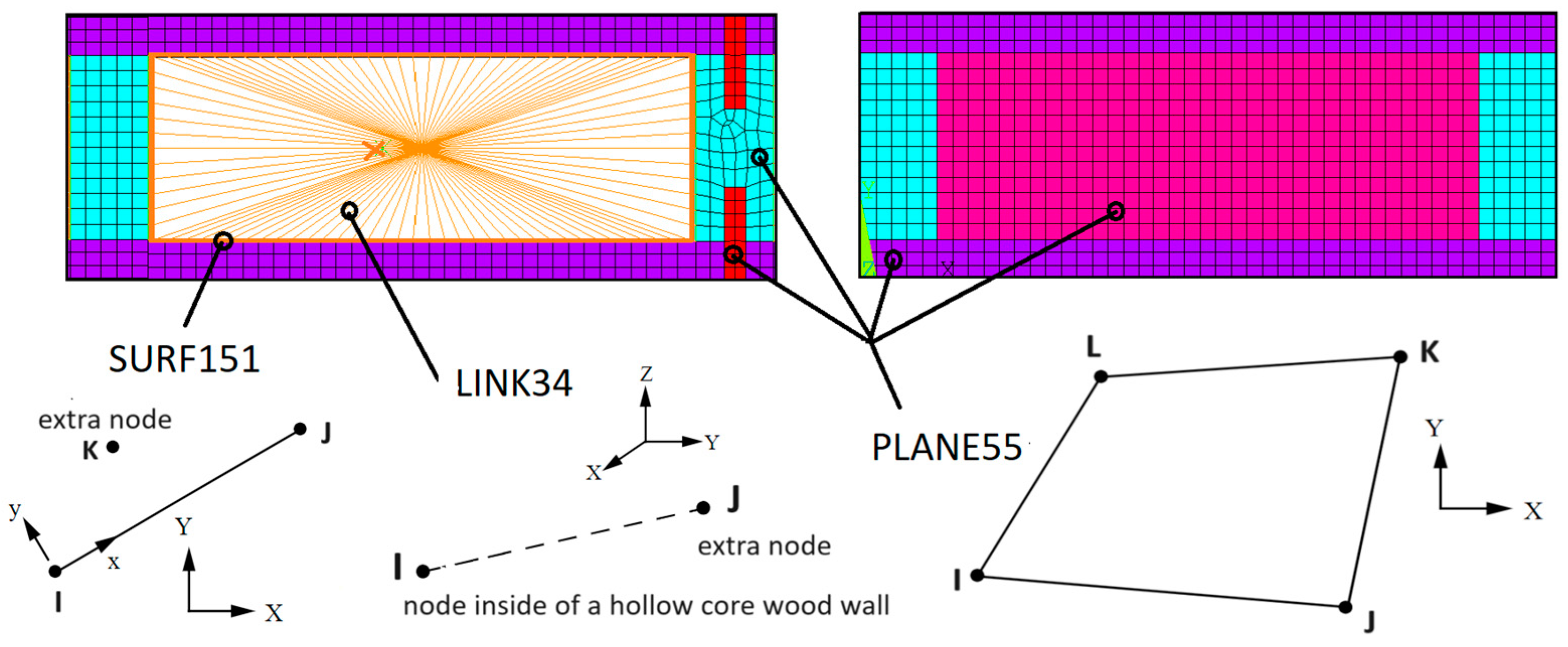
3.1. The Finite Element Method

For the application of the finite element method, the ANSYS® program [19] was used for the transient and nonlinear material thermal analysis [5,6]. To represent a typical plane of the wall partition model, a 2D mesh was built.
In the numerical model, the mesh size was calculated by observing the lower dimension, that is, the gypsum material. In these regions, the number of finite elements was adjusted to three (less than 10 mm), and it was ensured that they were of the same length throughout the mesh. Figure 3 shows the mesh used in the studied models.
In all the numerical simulations, no iteration was considered between the materials. The contact between them was perfect, allowing for thermal energy conduction between them. The 2D numerical model has already been validated in previous works [6,7] with the elements PLANE55, SURF151, and LINK34, as shown in Figure 3.
PLANE55 is a 2D thermal solid element with four nodes and a one-degree-of-freedom temperature at each node. The element is suitable for steady-state or transient conditions [5,6,19].
SURF151 is a surface thermal element with two nodes and is used for radiation between the internal surfaces of a cavity and any point inside it as an extra node [6,7,19].
LINK34 is a uniaxial convection link element with the capacity to conduct heat between its two nodes, and is appropriate in steady-state or transient conditions. The element has one degree of freedom, the temperature at each node, one node on the surface, and another inside the cavity [6,7,19].

3.2. The Thermal Material Properties

The materials used in the studied model are wood GL32H and gypsum board type F, both obtained from references [4,12,20]. The numerical model considers the variation in material properties in terms of temperature. The thermal material properties needed to be considered in all analyses are presented in Table 2, Table 3, Table 4 and Table 5.
The wood material is glulam type GL32H with a density equal to 480 kg/m3 and gypsum board type F with a density equal to 889 kg/m3, as considered in a previous publication [4,12,20]. Wood density is a function of the moisture content, as reflected by the ratio presented in Table 3, with an initial moisture content of 12%, a value derived from [12].
The insulation material has properties related in the bibliography for fiberglass [14] based on experimental and numerical analyses.
The thermal materials properties for steel follow Eurocode 3, part 1–2 [23].

3.3. The Boundary Conditions

The boundary conditions involved in all the analyses conform to Eurocode 1 part 1–2 [10], allowing the imposition of the fire effect in the wall partition. The boundary conditions are the following:
-
Radiation and convection on the wall partition side exposed to fire, with the imposed standard fire curve from ISO 834 [11];
-
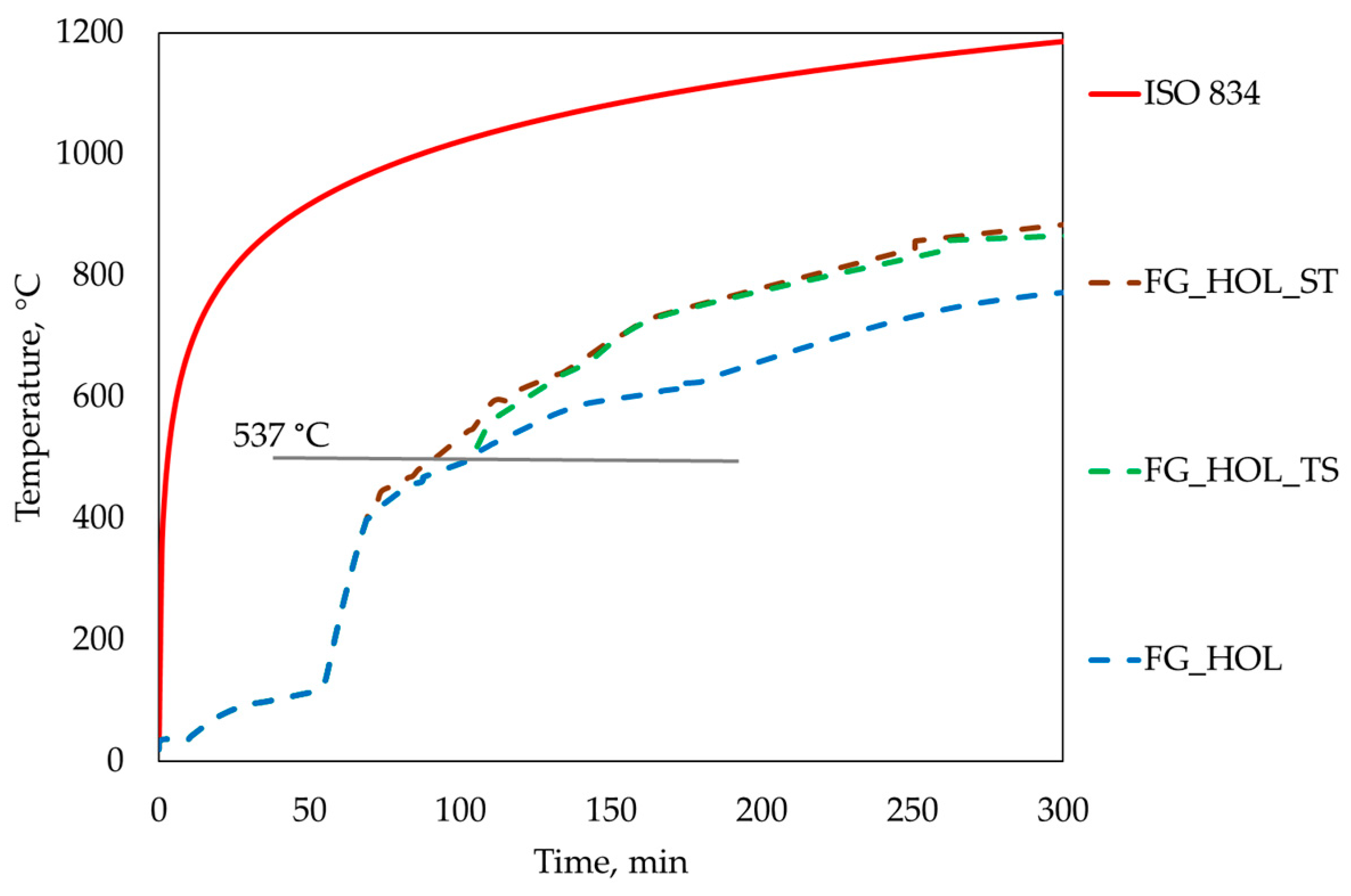
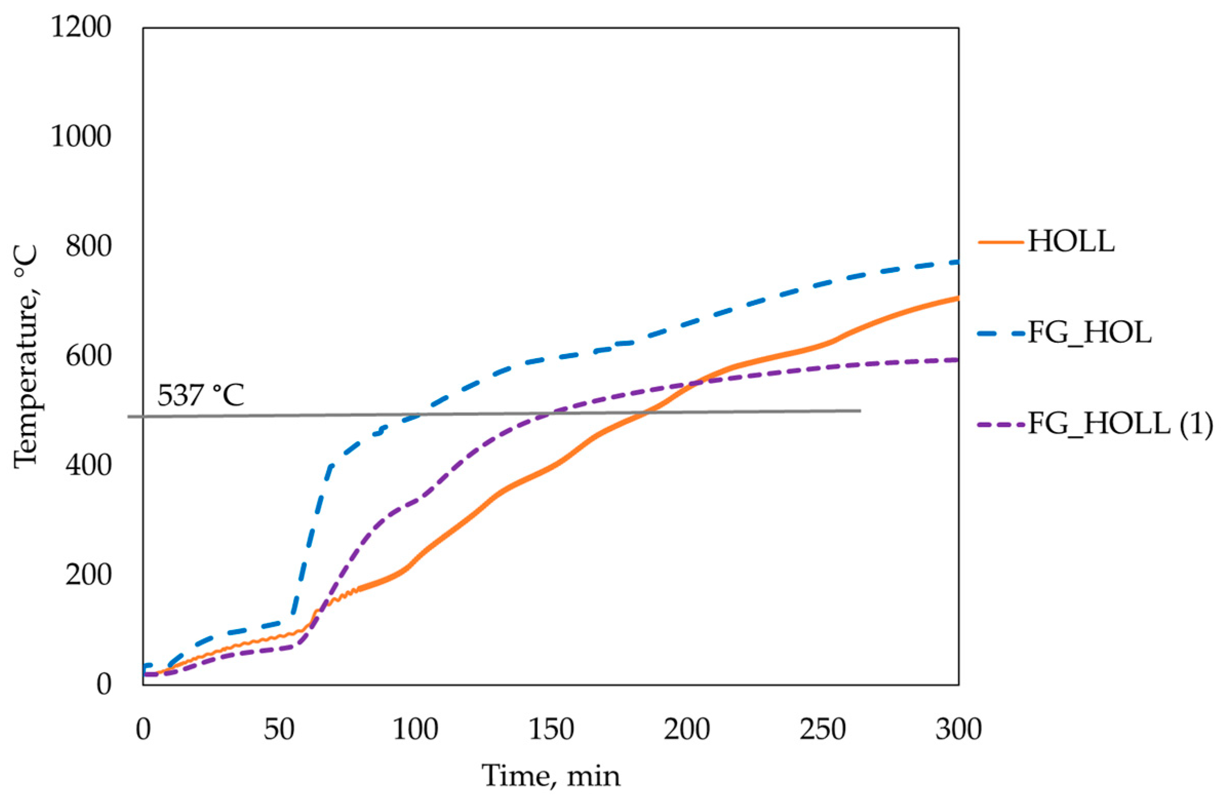
Radiation and convection on the cavity, with the temperature evolution through the curves FG_HOL_ST, FG_HOL_TS, and FG_HOL;
-
Convection on the side not exposed to fire;
-
Adiabatic or no applied conditions on the lateral edges;
-
An ambient temperature of 20 °C considered as the initial condition.
Under these conditions, the relative emissivity of the wood material was 0.8 and 0.85 for gypsum board [6,7]. The emissivity of fiberglass was considered equal to 0.75 [14]. And the emissivity of steel was considered equal to 0.7 [23]. The emissivity of the environment was equal to 1, with the convection equivalent to 25 W/m2 K on the exposed face and 9 W/m2 K on the opposite side not exposed to fire, according to Eurocode 1 part 1–2 [6,7,10]. In the cavities, a convection coefficient of 17.5 W/m2 K was considered [6,7].
ANSYS® program [19] uses the Newton–Raphson method as an iterative method to allow for nonlinear conditions in the solution of the problem. Simultaneously, a convergence criterion based on the heat flow with a tolerance equal to 0.9 was used, with other variables considered as standard parameters.
In Figure 4, all models are represented, as shown in Table 1. The HOLL numerical model, previously tested [6,7], is was made up of plane elements and surface elements for the modeling of gypsum board and wood, only bonded with ribs. The HOLL_ST model incorporates steel-threaded screws, which allows for a connection between the gypsum and wood materials. The HOLL_TS model contains the same screws but without threading.
The FG_HOL numerical model is made up of plane elements for the modeling of gypsum board, wood, and internal insulation material, which are also bonded with ribs. The FG_HOL_ST model incorporates steel-threaded screws. The FG_HOL_TS model contains the same screws but without threading.
For the FG_HOL model, two different models were considered. The first (1) one with an internal mesh in the cavity represented the insulation material. The other one (2) came without any internal mesh but considered the temperature evolution inside the hollow part.
Figure 5 represents the different curves that needed to be imposed as boundary conditions in all the numerical models, such as the temperature evolution. The external fire curve (ISO 834) [10] is to be imposed on all the models. Three more curves (FG_HOL, FG_HOL_TS, FG_HOL_ST), obtained from the previous numerical calculations on FG_HOL with internal insulation mesh, are to be combined with the temperature in the hollow cavity of HOLL, HOLL_ST, and HOLL_TS, after the melting point of 537 °C in fiberglass. Each one is introduced in the cavity of the respective models with fiberglass FG.
Fiberglass can resist high temperatures, with its average melting point being 537 °C [24]. It will not burn and can withstand continuous exposure up to this temperature. It is used to protect from and does not catch fire, preventing fire from passing through it, reducing its spread [24].
To identify the typical curves, Figure 6 shows the procedure for the temperature evolution FG_HOL. This curve was obtained with the temperature calculation inside the cavity in FG_HOL (1), where the material properties of the fiberglass were incorporated in the solid mesh until the fiberglass degradation and the combination with the internal temperature calculated in the HOLL model reached 537 °C. This curve identifies the temperature evolution needed inside the cavity FG_HOL to promote the boundary conditions internally in the hollow members with convection and radiation. The curve FG_HOL was introduced in a middle node on each cavity.
The other curves in Figure 5 were the same procedure. The curve FG_HOL_ST was obtained with the models combined between HOLL_ST and FG_HOL (1). The curve FG_HOL_TS was obtained with the combination of HOLL_TS and FG_HOL (1).

4. Results and Discussion of the Wall Partition Model

4.1. The Fire Resistance

The fire resistance is the time, in minutes, at which the wall partition retains the capability to restrain a fire or the time at which the failure of the element happens [4,6,7]. For the present study and to obtain the fire resistance, it was necessary to apply the thermal insulation criterion, defined by the EN 1363-1:2020 standard [8], where the elements collapse when the insulation criterion is reached, concerning the average Tave = 160 °C or maximum Tmax = 200 °C temperature on the side not exposed.
To estimate the fire resistance, obtaining the temperature history at different nodes on the unexposed side is essential. Thirteen nodes were considered to get the mean and maximum temperature, which fulfils the thermal insulation criterion, given to EN1363-1:2020 [8], as represented in Figure 7.
Regarding the results, the numerical model HOLL reaches 269 min of fire resistance, which agrees with the results of the previous research [6], showing a fire resistance of 253.5 min. The deviation in 15.5 min is given by the solution run, obtained with a different time step in the numerical model. In all models, the used time step was equal to 10 s with a minimum increment of 1 s. The maximum and the minimum temperatures for the HOLL model are represented in Figure 7 and are also compared with those of the previous model [6] with a minimum value equal to 62.6 °C and a maximum of 149 °C. The current values are equal to 66 °C and 149.9 °C.
After comparison with the previous results in [6], the main goal was to verify the effect of the screw elements in the wall partition. The numerical models HOLL_ST and HOLL_TS showed a decrease in fire resistance of 74 min and 71 min, respectively. The effect of steel screws was very important in the heat transferred to the wall partition. Regarding the screws with or without threads, there was only a 3 or 4 min increase in fire resistance when using the screws with threads.
Comparing the results of the fire resistance between the models HOLL and FG_HOL, there was a reduction of 46 min. Between the models HOLL_ST and FG_HOL_ST, the reduction was 45 min, and between HOLL_TS and FG_HOL_TS, the reduction was 44 min. On average, the fire resistance decreased by 45 min in the models, considering the thermal effect of fiberglass.

4.2. Fire Resistance in the Models

Using the results, it was possible to verify the temperature in all the numerical models to calculate the duration of fire resistance, as presented in Figure 8. The temperature field images display the temperature distribution, between the range of the maximum and minimum values reached in all models.
As a brief summary, some studies present fire performance with the use of screws for connections in wooden constructions, while others refer to the use of high-strength steel screws with significant advances in resistance to high temperatures. Additionally, some studies refer to the significant structural changes in steel materials that are strongly dependent on the temperature reached [25,26,27]. The results were used to develop design principles in the fire resistance of bolted connections, where it was found that the temperature profiles through wooden parts depend primarily on the relative exposure of the wood and steel elements, as well as the fire duration [25]. The insulating effect of wood and the smaller heated area of exposed screws restrained thermal conduction across the cross-section and prevented the extent of charring of the components [25]. Furthermore, analytical models under different conditions were proposed to predict the strength degradation of bolted joints under high temperatures, suggesting applications of high-strength fire-resistant bolts in practical engineering [26]. In fire situations, microstructural changes can affect the behavior of steel bolts, determining how the structure will fail [27].
In this work, outcomes were achieved according to the following three different considerations (A–C).
A
The comparison of results between the models with and without fiberglass showed the following:
-
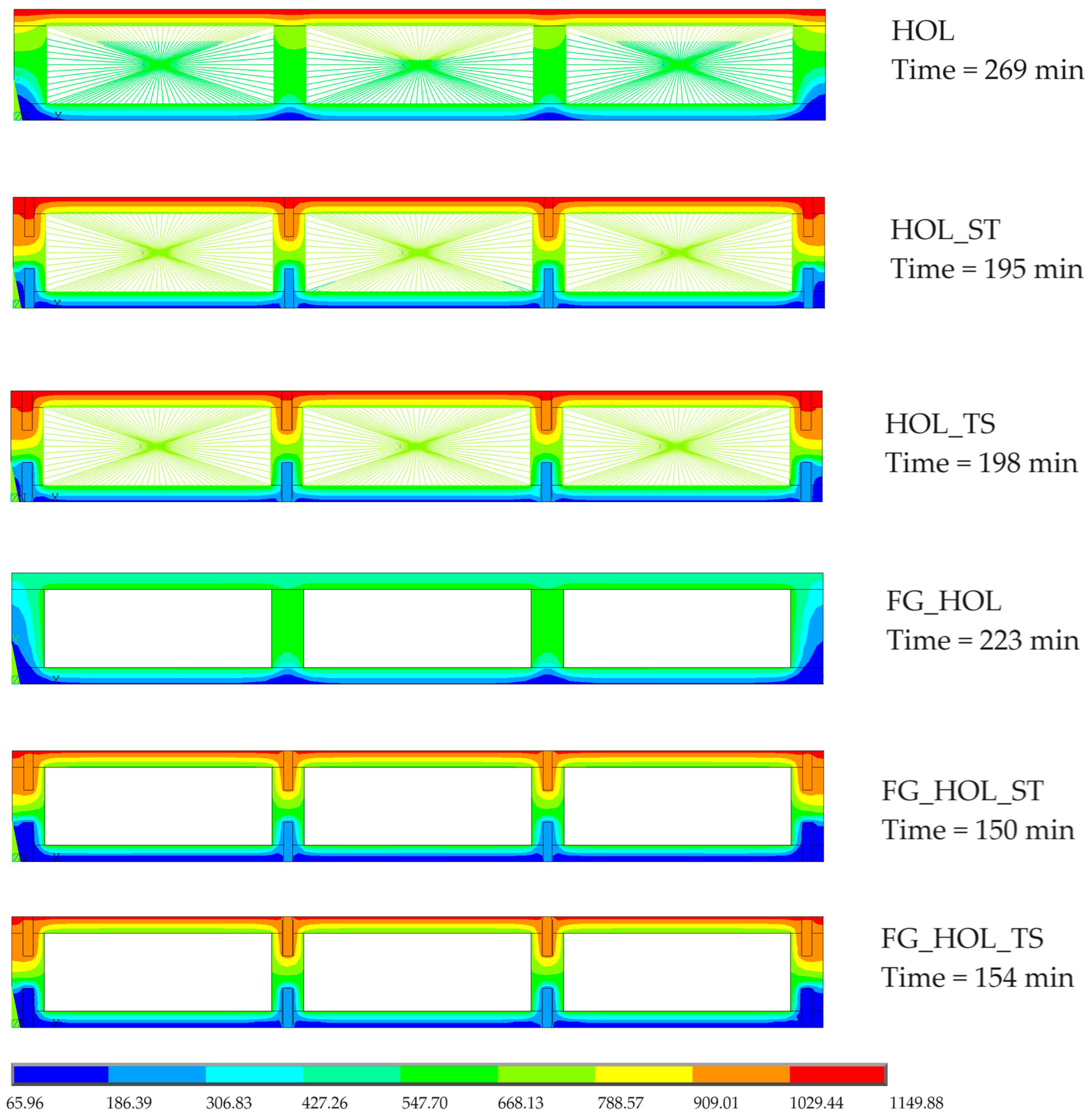
In the models without fiberglass, the temperatures inside the cavity were not uniform, as represented through the wooden walls inside. In these models, the temperature inside the cavity was higher at the top and lower at the bottom.
-
The models with fiberglass achieved lower temperatures inside their cavities, maintaining more uniform heating both at the top and bottom. This was due to the temperature evolution curve, presented in Figure 5, which shows the properties of the fiberglass until a temperature of 537 °C is reached. In models with fiberglass, heating inside the cavity increased until the temperature of the material reached 619.8 °C (model FG_HOL), which affected fire resistance in terms of decreasing its duration.
B
The comparison of results between the models with and without steel screws showed the following:
-
The models without screws maintained a constant temperature throughout the thickness of the wooden elements;
-
The models with steel screws transmitted greater heat around them, thus affecting the wooden elements;
-
The temperature in steel screws near the top increased due to the gypsum being exposed to fire, while screws on the bottom side were of lower temperatures;
-
There were no differences in the results between the use of screws with or without threading.
C
A comparison of the time fire resistance between all the models showed the following:
-
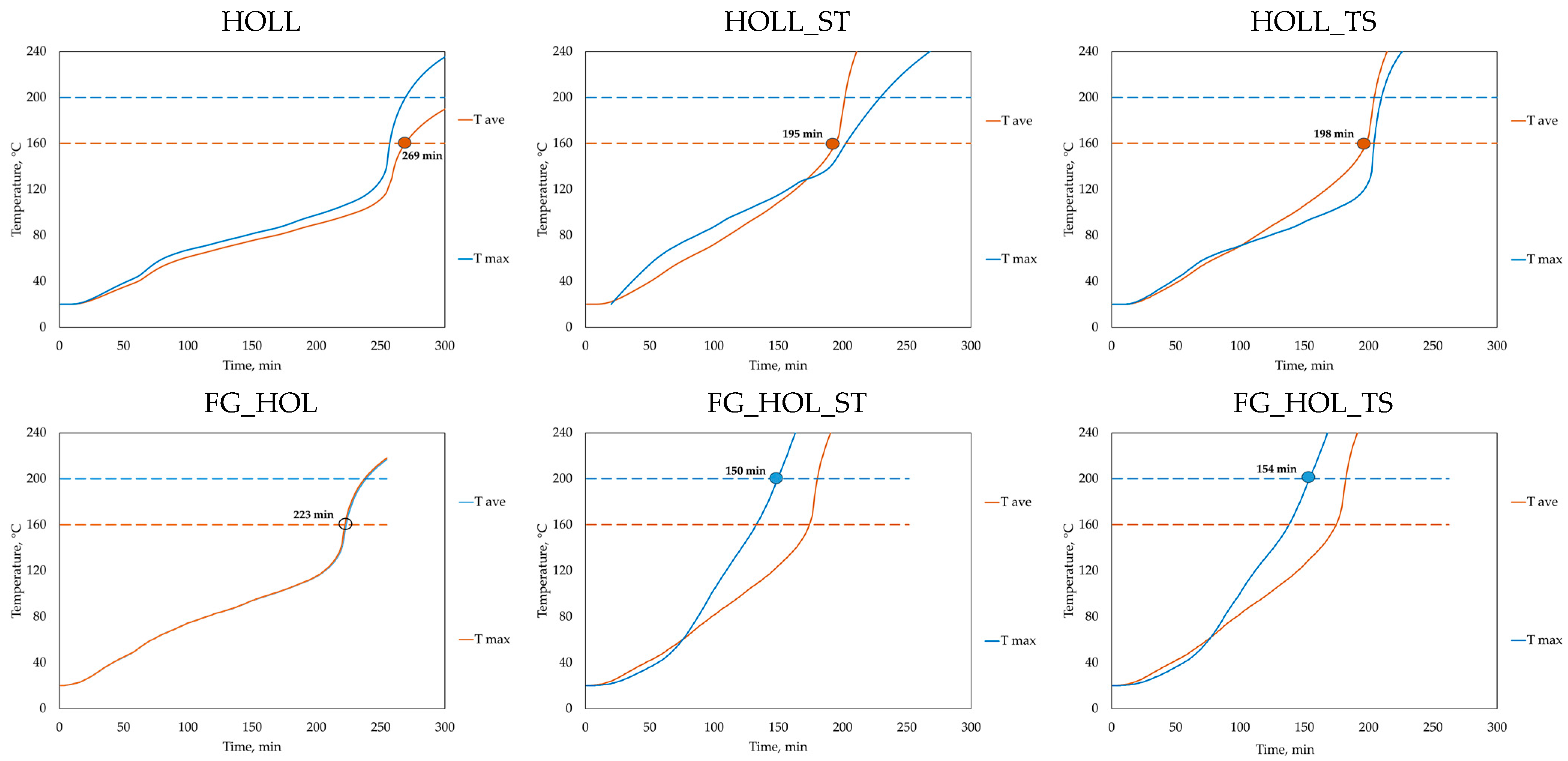
The fire resistance duration of the models with fiberglass decreased by 45 min as the mean, compared with that of models without insulation inside the cavities;
-
The duration of fire resistance also decreased by 71.75 min as the mean when steel screws were considered in the numerical simulation.
-
The comparison between the use of screws, with and without threads, showed a duration of only 3.5 min of fire resistance.

5. Conclusions

In this work, different numerical models of typical wall partitions, protected by gypsum board exposed to fire, simulated the influence of the use of steel screws to assemble the elements and of the insulation material inside the cavities. The aim was to calculate the duration of fire resistance, using the thermal insulation criterion, with all those variables.
The main conclusions are the following:
-
For the duration of fire resistance, in the numerical models filled with fiberglass, the heating inside the cavity increased until the material reached a temperature of 619.8 °C (model FG_HOL). These models had lesser fire resistance when compared to models without fiberglass inside their cavities, with a mean duration of less than 45 min. This value is noticeable due to the heat produced by the insulated material inside the cavity in permanent contact with the wood element until its degradation. The wall partition filled with fiberglass reached a duration of 223 min of fire resistance.
-
The models without fiberglass showed greater heating near the top of the model but greater resistance to heating in the lower part. The gypsum material transmitted heat into the cavities, which promoted a temperature increase through the wood elements, from the top side bordering the fire to the unexposed bottom side. Due to wood’s lower conductivity, the increased temperature on the unexposed side was lower and allowed for higher fire resistance. The wall partition without insulation material inside the cavity reached a duration of 269 min of fire resistance.
-
The steel screws in the previous models allowed them to concentrate greater heat and thus distribute greater heat around them to the wooden elements. The use of steel screws decreased the duration of fire resistance by 71.75 min as the mean, independent of the use of a wall partition with or without filled insulation material.
In future work, the presented results will be used to verify the analytical model proposed by Frangi et al. [20]. Also, we intend to construct more new numerical models filled with other insulation materials to test their thermal performance, and to compare the results of this with those of the present study.

Author Contributions

Conceptualization, E.M.M.F.; methodology, M.O.; validation, M.O.; investigation, M.O.; writing—original draft preparation, D.P.; writing—review and editing, E.M.M.F.; supervision, E.M.M.F. All authors have read and agreed to the published version of the manuscript.

Funding

This research received no external funding.

Institutional Review Board Statement

Not applicable.

Informed Consent Statement

Not applicable.

Data Availability Statement

The original contributions presented in the study are included in the article, further inquiries can be directed to the corresponding author.

Conflicts of Interest

The authors declare no conflicts of interest.

References

  1. Winchester, N.; Reilly, J.M. The economic and emissions benefits of engineered wood products in a low-carbon future. Energy Econ. 2020, 85, 104596. [Google Scholar] [CrossRef]
  2. Balasbaneh, A.T.; Sher, W. Comparative sustainability evaluation of two engineered wood-based construction materials: Life cycle analysis of CLT versus GLT. Build. Environ. 2021, 204, 108112. [Google Scholar] [CrossRef]
  3. Hildebrandt, J.; Hagemann, N.; Thrän, D. The contribution of wood-based construction materials for leveraging a low carbon building sector in Europe. Sustain. Cities Soc. 2017, 34, 405–418. [Google Scholar] [CrossRef]
  4. Yang, T.-H.; Wang, S.-Y.; Tsai, M.-J.; Lin, C.-Y. The charring depth and charring rate of glued laminated timber after a standard fire exposure test. Build. Environ. 2009, 44, 231–236. [Google Scholar] [CrossRef]
  5. Žajdlík, T.; Šuhajda, K.; Průša, D. Medium-Scale Fire Resistance Testing of Timber Structures with Composite Cement Fibre Materials. Buildings 2023, 13, 527. [Google Scholar] [CrossRef]
  6. Pereira, D.; Fonseca, E.M.M.; Osório, M. Temperature Evolution inside Hollow Core Wood Elements and Fire Resistance. Fire 2024, 7, 57. [Google Scholar] [CrossRef]
  7. Pereira, D.; Fonseca, E.M.M.; Osório, M. Computational Analysis for the Evaluation of Fire Resistance in Constructive Wooden Elements with Protection. Appl. Sci. 2024, 14, 1477. [Google Scholar] [CrossRef]
  8. CEN. EN 1363-1; Fire Resistance Tests Part 1: General Requirements. CEN: Brussels, Belgium, 2020.
  9. CEN. EN 1364-1; Fire Resistance Tests for Non-Loadbearing Elements. Part 1: Walls. CEN: Brussels, Belgium, 2015.
  10. CEN. EN1991-1-2; Eurocode 1: Actions on Structures. Part 1–2: Structural Fire Design. BSI: Brussels, Belgium, 2010.
  11. ISO 834-1; Fire Resistance Tests-Elements of Building Construction—Part 1: General Requirement. International Organization for Standardization: Geneva, Switzerland, 1999. Available online: https://www.iso.org/standard/2576.html (accessed on 20 November 2023).
  12. CEN. EN1995-1-2; Eurocode 5: Design of Timber Structures. Part 1–2: General Structural Fire Design. BSI: Brussels, Belgium, 2004.
  13. Kumar, D.; Alam, M.; Zou, P.X.; Sanjayan, J.G.; Memon, R.A. Comparative analysis of building insulation material properties and performance. Renew. Sustain. Energy Rev. 2020, 131, 110038. [Google Scholar] [CrossRef]
  14. Papadopoulos, A.M. State of the art in thermal insulation materials and aims for future developments. Energy Build. 2005, 37, 77–86. [Google Scholar] [CrossRef]
  15. Cao, X.; Liu, J.; Cao, X.; Li, Q.; Hu, E.; Fan, F. Study of the thermal insulation properties of the glass fiber board used for interior building envelope. Energy Build. 2015, 107, 49–58. [Google Scholar] [CrossRef]
  16. Xu, Q.; Wang, Y.; Chen, L.; Gao, R.; Li, X. Comparative experimental study of fire-resistance ratings of timber assemblies with different fire protection measures. Adv. Struct. Eng. 2016, 19, 500–512. [Google Scholar] [CrossRef]
  17. Abu-Jdayil, B.; Mourad, A.H.; Hittini, W.; Hassan, M.; Hameedi, S. Traditional, state-of-the-art and renewable thermal building insulation materials: An overview. Constr. Build Mater. 2019, 214, 709–735. [Google Scholar] [CrossRef]
  18. Takeda, H.; Mehaffey, J.R. WALL2D: A Model for Predicting Heat Transfer through Wood-Stud Walls Exposed to Fire. Fire Mater. 1998, 22, 133–140. [Google Scholar] [CrossRef]
  19. ANSYS, Inc. ANSYS Mechanical APD 2022 R2; Release 2; ANSYS, Inc.: Southpointe, PA, USA, 2022. [Google Scholar]
  20. Frangi, A.; Schleifer, V.; Fontana, M.; Hugi, E. Experimental and Numerical Analysis of Gypsum Plasterboards in Fire. Fire Technol. 2010, 46, 149–167. [Google Scholar] [CrossRef]
  21. C04 Partitions, Non-Loadbearing Timber Stud. Traditional Stud Partitions. White Book S11, 275–286, Ireland. Available online: https://www.gyproc.ie/en/assets/download/media/1306 (accessed on 4 March 2024).
  22. Pang, S.J.; Ahn, K.S.; Oh, J.W.; Lee, H.S.; Kang, S.G.; Oh, J.K. Fire Resistance of Structural Wooden Walls Covered by Gypsum and Diatomite Board. BioResouces 2023, 18, 991–1007. [Google Scholar] [CrossRef]
  23. CEN, EN1993-1-2; Eurocode 3: Structural Fire Design. Part 1–2: General Rules. BSI: Brussels, Belgium, 2005.
  24. San Diego Seal, Inc. Fiberglass Fabric Cloth, High Temperature, Heat & Flame Resistant Thermal Insulating; SDSI Industrial & Marine Sealing Devices: San Diego, CA, USA, 2024; Available online: http://sandiegoseal.com/pdf/fibercloth.pdf (accessed on 4 March 2024).
  25. Létourneau-Gagnon, M.; Dagenais, C.; Blanchet, P. Fire Performance of Self-Tapping Screws in Tall Mass-Timber Buildings. Appl. Sci. 2021, 11, 3579. [Google Scholar] [CrossRef]
  26. Wang, Y.; Li, X.; Liu, P.; Wu, C.; Liu, C.; Zeng, L.; He, W.; Yin, T. Mechanical Behavior of High-Strength Bolted Joints Fabricated from Fire-Resistant Steel at Elevated Temperatures. Adv. Mater. Sci. Eng. 2022, 2022, 8265019. [Google Scholar] [CrossRef]
  27. Król, P.A.; Wachowski, M. Effect of Fire Temperature and Exposure Time on High-Strength Steel Bolts Microstructure and Residual Mechanical Properties. Materials 2021, 14, 3116. [Google Scholar] [CrossRef] [PubMed]
Figure 1. Typical wall partition and used materials with one side exposed to fire.
Fire 07 00288 g001
Figure 2. Two-dimensional wall partition with typical dimensions.
Fire 07 00288 g002
Figure 3. Two-dimensional mesh and finite elements. The light-blue color represents the wood, the violet color represents the gypsum board, the orange color represents the edge of the surface, the red color represents the screw, and the pink color represents the fiberglass. “X” in the middle represents the point where the finite element is connected.
Fire 07 00288 g003
Figure 4. Wall partition, mesh, and materials. The light-blue color represents the wood, the violet color represents the gypsum board, the yellow-shaded area outlines the mesh in the cavity, the red color represents the mesh on the screws, and the pink mesh represents the insulation material. “X” in the middle represents the point where the finite element is connected.
Fire 07 00288 g004
Figure 5. Curves need to be imposed as boundary conditions in all numerical models.
Fire 07 00288 g005
Figure 6. Curves need to be imposed as boundary conditions in all numerical models.
Fire 07 00288 g006
Figure 7. Application of the thermal insulation criterion.
Fire 07 00288 g007
Figure 8. The temperature distribution in the wall partition at the time of fire resistance.
Fire 07 00288 g008
Table 1. Wall partition models in this study.
Wall Partition Model Type:DesignationMaterials
Hollow cavitiesHOLLWood and gypsum
Hollow cavities screwed with threadHOLL_STWood, gypsum, and steel screw thread
Hollow cavities screwed without threadHOLL_TSWood, gypsum, and steel screw threadless
Filled hollow cavities with insulationFG_HOLWood, gypsum, and fiberglass
Hollow cavities insulated and screwed with threadFG_HOL_STWood, gypsum, fiberglass, and steel screw thread
Hollow cavities insulated and screwed without threadFG_HOL_TSWood, gypsum, fiberglass, and steel screw threadless
Table 2. Steel.
Table 2. Steel.
Temperature,
°C
Density,
kg/m3
Temperature,
°C
Specific Heat, kJ/kgKTemperature,
°C
Thermal Conductivity, W/mK
207850200.4402053.334
500.460799–120027.393
1000.488
1500.510
2000.530
2500.547
3000.565
3500.584
4000.606
4500.633
5000.667
5500.708
6000.760
6500.814
7001.008
7302.291
7355.000
7501.483
7850.875
8000.803
8250.735
8500.695
8900.657
12000.650
Table 3. Wood.
Table 3. Wood.
Temperature,
°C
Density,
kg/m3
Temperature,
°C
Specific Heat, kJ/kgKTemperature,
°C
Thermal Conductivity, W/mK
20(1 + 0.12) * 537.6201.53200.12
99(1 + 0.12) * 537.6991.772000.15
120(1.0) * 480.010013.603500.07
200(1.0) * 480.012013.505000.09
250(0.93) * 446.41212.128000.35
300(0.76) * 364.82002.0012001.50
350(0.52) * 249.62501.62
400(0.38) * 182.43000.71
600(0.28) * 134.43500.85
800(0.26) * 124.84001.00
1200(0) * 0.06001.40
8001.65
12001.65
* Density ratio.
Table 4. Fiberglass.
Temperature,
°C
Density,
kg/m3
Temperature,
°C
Specific Heat, kJ/kgKTemperature,
°C
Thermal Conductivity, W/mK
2015.00200.84200.045
Table 5. Gypsum type F.
Temperature,
°C
Density,
kg/m3
Temperature,
°C
Specific Heat, kJ/kgKTemperature,
°C
Thermal Conductivity, W/mK
20889.00200.95200.190
100889.001000.951950.190
170737.8713525.001550.100
600737.871700.952000.103
750700.986500.954000.113
1200700.9867510.006000.127
7000.958000.145
12000.9512000.165
Disclaimer/Publisher’s Note: The statements, opinions and data contained in all publications are solely those of the individual author(s) and contributor(s) and not of MDPI and/or the editor(s). MDPI and/or the editor(s) disclaim responsibility for any injury to people or property resulting from any ideas, methods, instructions or products referred to in the content.

