Abstract
An experimental study was carried out on the ignition and combustion processes of particles (100–200 µm in size) of coals of different degrees of metamorphism and biomass, as well as mixtures based on them, under conditions of conductive and convective heating, which correspond to the conditions of fuel ignition in boiler furnaces at grates and flaring combustion. The biomass contents in the composition of the coal-based fuel mixtures were 10, 20, and 30 wt.%. Under the conductive (at 700–1000 °C) and convective (at 500–800 °C) heating of fuel particles, ignition delay times were determined using a hardware–software complex for the high-speed video registration of fast processes. The ignition delay times were found to vary from 1 to 12.2 s for conductive heating and from 0.01 to 0.19 s for convective heating. The addition of 10–30 wt.% biomass to coals reduced the ignition delay times of fuel mixtures by up to 70%. An analysis of the flue gas composition during the combustion of solid fuels allowed us to establish the concentrations of the main anthropogenic emissions. The use of biomass as an additive (from 10 to 230 wt.%) to coal reduced NOx and SOx emissions by 19–42% and 24–39%, respectively. The propensity of fuels to cause slagging depending on their component composition was established. The use of up to 30 wt.% of biomass in the mixture composition did not affect the increase in the tendency to cause slagging on heating surfaces in the boiler furnace and did not pose a threat to the layer agglomeration during the layer combustion of the mixtures.
1. Introduction
A number of agreements have been adopted to reduce greenhouse gases globally, such as the “Kyoto Protocol”, adopted in 1997, which has not yielded adequate results. In 2015, the “Paris Agreement” was adopted, but it is predicted that by the end of this century, there will be a significant increase in the temperature targets of the “Paris Agreement” [1]. Most greenhouse gases are generated and emitted into the environment by solid fossil fuel energy production. The amount of heat and electricity generated from fossil fuels in OECD (Organisation for Economic Co-operation and Development) countries is 80%, of which 38% is generated by coal, 28% by gas, and 14% by oil. By 2050, energy consumption in OECD countries is expected to increase by 15% [2,3]. An 80% increase in heat and power generation by 2050 could lead to a 70% increase in carbon dioxide emissions, so there is an increased need to involve carbon-neutral fuels in the fuel and energy mix to replace the fossil fuels currently being used [4,5].
The scientific community has been developing ways to reduce the amount of fossil fuels consumed and, consequently, CO2 emissions released into the atmosphere. One of the ways this is achieved is the co-combustion of coal and biomass [6,7]. Currently, most technological equipment used for power generation is designed for coal combustion. In order to use coal-fired power plants at full capacity with the lowest modernization costs, the most feasible option is the co-combustion of coal with biomass at existing power plants [8,9]. This solution is one of the most profitable and efficient ways to use biomass to replace fossil fuels for energy production [10,11,12]. Often, the reason for carrying out the co-combustion of small amounts of biomass with coal is to utilize waste that is generated in forestry and agriculture. Adding biomass to a coal-fired boiler does not affect or, in the worst case, slightly reduces the overall efficiency of electricity generation in a coal-fired power plant [11]. Also, the results of many studies indicate that the co-combustion of coal and biomass helps to reduce the emissions of other harmful substances, such as CO, NOx, and SOx [9,13]. Despite the advantages of biomass in aspects of carbon reduction and the achievement of neutrality, it has disadvantages, such as a low calorific value, a hydrophilic particle surface, and the formation of slag deposits on heating surfaces [14,15]. One of the important advantages of coal and biomass co-combustion is the minimal reconstruction costs of existing coal-fired boilers while achieving reduced coal consumption, lower harmful emissions, and fine ash, as well as reduced carbon dioxide emissions. The ratio of coal to biomass can be up to 50% depending on the combustion technology. The co-combustion of biomass with coal also allows the utilization of industrial carbon-containing waste, which in turn presents a threat to the environment and creates a fire hazard when biomass waste is stored outdoors [16,17]. Biomass, compared to coal, has many advantages, one of which is that biomass is considered to be free industrial waste, the cost of which depends only on the distance of its delivery. Also, biomass belongs to renewable energy sources and is divided into seasonal (agricultural crops and others) and year-round (wood waste, sewage residues, solid waste, and others) types [18,19].
The peculiarity of the combustion of fuel mixtures is that biomass has a higher yield of volatiles. As a result, the time of fuel burnout decreases [20]. On the other hand, this imposes additional requirements to the organization of the combustion process: first of all, volatiles should be mixed well with secondary air. Small impurities such as sulfur, chlorine, potassium, and sodium can have the greatest influence [21]. Biomass is characterized by a relatively low sulfur content but significant amounts of calcium and sodium, which can lead to the binding of the sulfur contained in coal [22]. Compounds of calcium, sodium, potassium, magnesium, aluminum, silicon, and phosphorus contained in biofuel ashes lead to negative effects in boiler operation (slag deposits on the surfaces of heat exchangers in boiler furnaces) [23]. Operating costs increase in comparison with the costs of coal combustion. At the same time, the boiler efficiency decreases slightly, mainly due to the increase in fuel moisture, and the costs of its preparation increase.
In real-world practices, several methods of co-combustion are used. One of the simplest methods is mixing coal and biomass in the fuel store and combusting the mixture in a pulverized coal boiler [24]. The disadvantage of this method is the small (up to 5%) share of biomass. When there are separate inputs of coal and biomass in the furnace, it is possible to burn up to 50% of biomass in the pulverized coal boiler. The co-combustion of coal and biomass has demonstrated a number of positive effects (e.g., the reduction of sulfur oxide emissions at a low sulfur content in biomass and the interaction of calcium compounds in biofuel ashes with sulfur oxides emitted during coal combustion). Conversely, there are also negative effects, including the contamination of heating surfaces and the slagging and corrosion of heat exchange tubes, which can result in reductions in boiler efficiency and the reliability of their operation [9,25,26,27]. Thus, there is an urgent need to study the processes and optimize combustion modes during the co-combustion of coal and biomass, characterized by a difficult complex of physical and chemical interactions between the components in the processes of thermal decomposition and combustion.
Computation Fluid Dynamics (CFD) simulations [15,28] are useful to investigate the physical and chemical processes occurring during the co-combustion of coal and biomass in fluidized bed reactors at both the micro-scale and macro-scale. CFD simulations can provide insights into the characteristics of the co-combustion of coal and biomass, such as the co-combustion additive fraction, load fluctuations, fuel feed location, excess air, and air/fuel distribution, as well as determine the characteristics associated with heat release, unburned carbon, and pollutant emissions [15,28,29,30,31,32]. In CFD modeling of coal and biomass co-combustion processes, there are models of turbulent flow, gas-phase combustion, particle dispersion by turbulent flow, and coal/biomass volatile particle yield. Additionally, models related to the slagging and fouling of heating surfaces have been developed [29]. The research results obtained in this work provide a foundation for modeling the processes of co-combustion of coal and biomass in boiler furnaces.
Thus, the objective of this work is to examine the processes of ignition and combustion of biomass with coals of different degrees of metamorphism under conditions of convective and conductive heat supply. This investigation takes into account the tendency of mixtures to result in the slagging of heating surfaces and flue gas emissions.
2. Materials and Methods
2.1. Materials
In this study, a range of fuels were examined, including both individual fuels (coal and biomass) and their mixtures. The solid fossil fuels used were Bolshesyr lignite coal (Kansko-Achinsky coal basin, Russia) and Chernogorsk bituminous coal (Minusinsky coal basin, Russia). Birch sawdust (Forest Processing Plant, Russia) was used as a raw material of plant origin. Coal is quite widely used as the main fuel in thermal power plants. Birch is one of the most common types of wood in Russia. It is used in construction and the production of furniture and interior items. The processing of birch wood produces quite a large amount of waste, which can be used as an additive to solid fossil fuels. This paper explores fuels both individually and in mixed form, as presented in Table 1.

Table 1.
Investigated fuels.
The particles of solid fuels were obtained using a Retsch DM200 mill (Retsch GmbH, Haan, Germany). Following the grinding of individual fuels, the particles were sieved using a Retsch AS200 BASIC machine (Retsch GmbH, Haan, Germany). The final particle size of the coal and biomass was in the range of 100–200 μm, which corresponds to the typical particle size used in boiler furnaces [33]. Fuel mixtures were obtained by mechanically mixing coal and biomass (Table 1).
Technical and elemental analyses of fuels were performed using the following standard methods [34]: ISO 11722:213; ISO 1171:2024; ISO 562:2010; ISO 1928:2020; and ASTM D5373-2021. Analytical studies were conducted using the following equipment [30]: Snol 7.2/1300 muffle furnace (AB Umega, Utena, Lithuania); C6000 calorimeter (IKA, Staufen, Germany); a Vario MACRO cube elemental analyzer (Elementar Analysensysteme GmbH, Langenselbold, Germany); and an MA-150 moisture analyzer (Sartorius, Göttingen, Germany). The results of the technical and elemental analyses are presented in Table 2.
Table 2.
Results of technical and elemental analyses of coal and biomass.
In order to establish the influence of particle structure on the processes of ignition and combustion, the surfaces of coal and biomass fuel particles were analyzed using a TM-4000 scanning electron microscope (HITACHI High-Technologies Corporation, Chiba, Japan). The main characteristics of the microscope are as follows: magnification power ranging from 10 to 100,000 times; depth of field set at 0.5 mm; accelerating voltage ranging from 5 to 15 kV; maximum sample size of up to 80 mm in diameter and 50 mm in height; and minimum displacement step set at 65 nm. The microscope is equipped with the Hitachi TM4000Plus desktop microscope microanalysis system, which includes a silicon drift detector with a working area of 30 mm2 and a guaranteed energy resolution of 137 eV (Mn Ka); the electron source is a pre-centered tungsten cathode.
The elemental content in coal and biomass was determined by X-ray fluorescence spectral analysis (XRF) using an S2 RANGER spectrometer (Bruker, Berlin, Germany). The sample preparation process for analysis was as follows: ash samples weighing 5 g (particle dispersity 100 μm) were thoroughly mixed with boric acid and pressed into 40 mm diameter pellets, and the content of elements was automatically converted to oxide form in the program EQUA ALL (Bruker, Berlin, Germany).
2.2. Experimental Setup for Conductive Heating
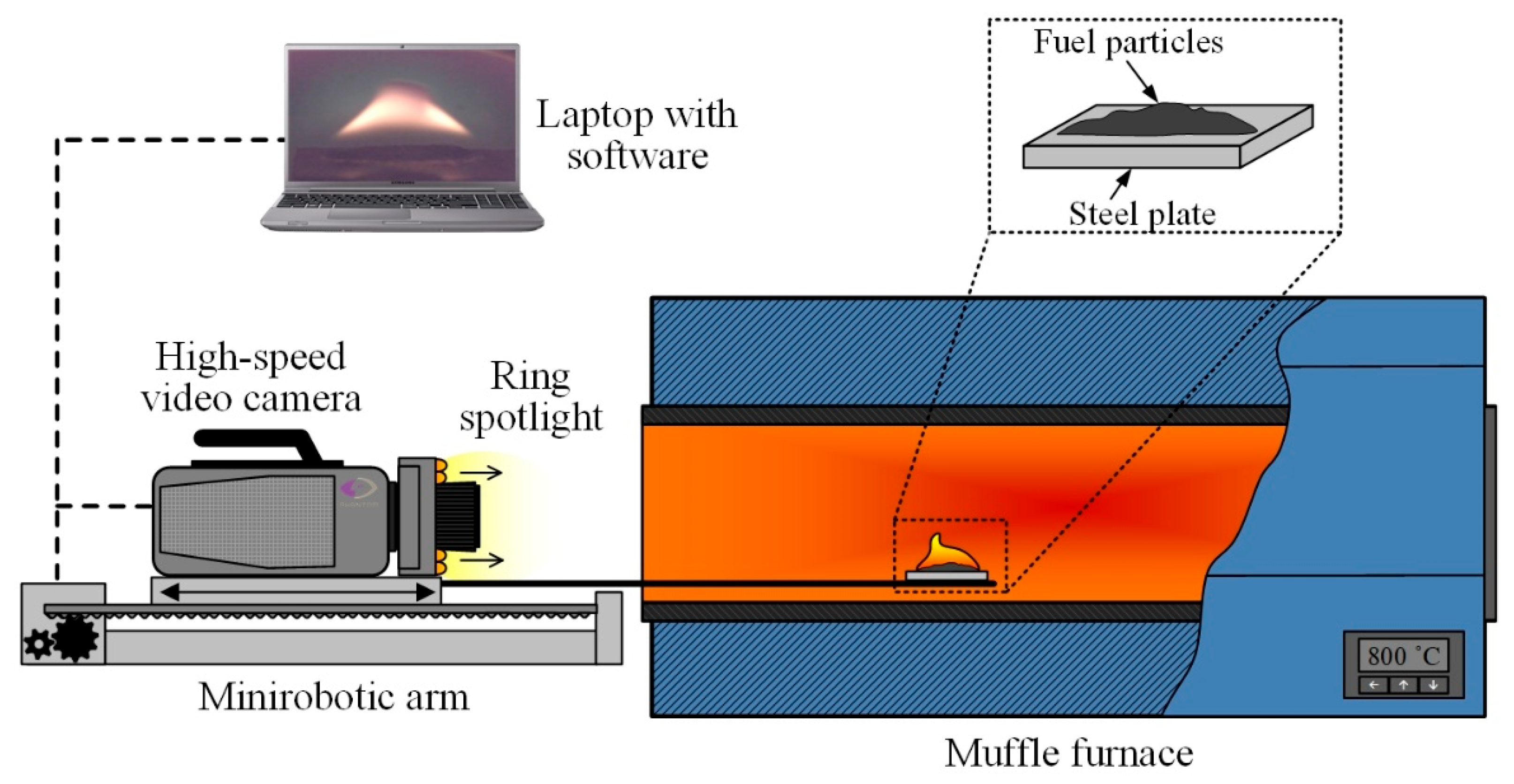
Experimental studies were conducted to explore the processes of ignition and combustion of fuel particles under conditions of conductive heating [35,36], the scheme of which is presented in Figure 1. The experiments were conducted under environmental conditions corresponding to laboratory conditions (a temperature of 23 °C, atmospheric pressure, and a relative humidity of 45%).

Figure 1.
Schematic diagram of the experimental setup for fuel combustion under conditions of conductive heating.
A high-temperature air environment (700–1000 °C) was generated within the cavity of a tubular muffle furnace Nabertherm R 50/250/13 (Nabertherm GmbH, Lilienthal, Germany). The inner diameter of the ceramic tube was 0.04 m and the length was 0.45 m; the temperature in the furnace was monitored using the signal of the built-in S-type thermocouple. In each series of 5–10 experiments conducted under identical initial conditions, the furnace was heated to the set temperature (Tg). On the surface of the steel plate, we applied suspensions of fuels with a mass of 0.04 g. Using the coordinate mechanism SPSh20-23017/2000Z (CJSC “Mechatronic Products Plant”, Povarovo, Russia), the steel plate with fuel particles was introduced into the muffle furnace cavity at a speed of no more than 0.1 m/s along the symmetry axis of the ceramic tube up to its middle (see Figure 1). The initial temperature of the substrate in each experiment, before its introduction into the muffle furnace, was kept constant at 23 °C, which corresponds to the laboratory’s room temperature, and was monitored using a Raytek RAYMX2TDU pyrometer (Raytek Corporation, Berlin, Germany) (with a measurement range of −30 to 1000 °C, an accuracy of ±0.75%, and a temperature of no less than ±1 °C). The system for high-speed video recording of fast processes consisted of a color high-speed video camera, Phantom V411 (Vision Research, Wayne, NJ, USA), located on a mini robotic arm, and a PC with commercial software Tema Automotive 3.9 (Image Systems AB, Linkoping, Sweden) installed. The shooting speed was 1000 fps at a resolution of 800 × 600 pixels. After each experiment, the substrates (the fuel heating surfaces) were cleaned of solid combustion residue using airflow at a pressure of 10 atmospheres. Ring illumination was used to increase the brightness of the image during the video recording.
In each experiment, the ignition delay times (td) of the fuels were recorded. The moment of the beginning of the steel plate’s heating with fuel at the beginning of the furnace’s muffle tube was taken as the beginning of the ignition delay time td, i.e., t = 0. The ignition of the vapor–gas mixture was considered as the end of the ignition delay time, t = td. The moment of ignition was registered within the algorithm of video recordings processing automatically upon reaching or exceeding the threshold value of luminosity intensity in any point of the video registration area. It was observed that the range of 220–255 in a black and white color scale corresponded to the combustion process (intensive exothermic reaction). The random inaccuracy in determining the ignition delay time in a series of 5–10 experiments was found to be no greater than 10%, whilst the systematic inaccuracy was 0.5%.
2.3. Experimental Setup for Convective Heating
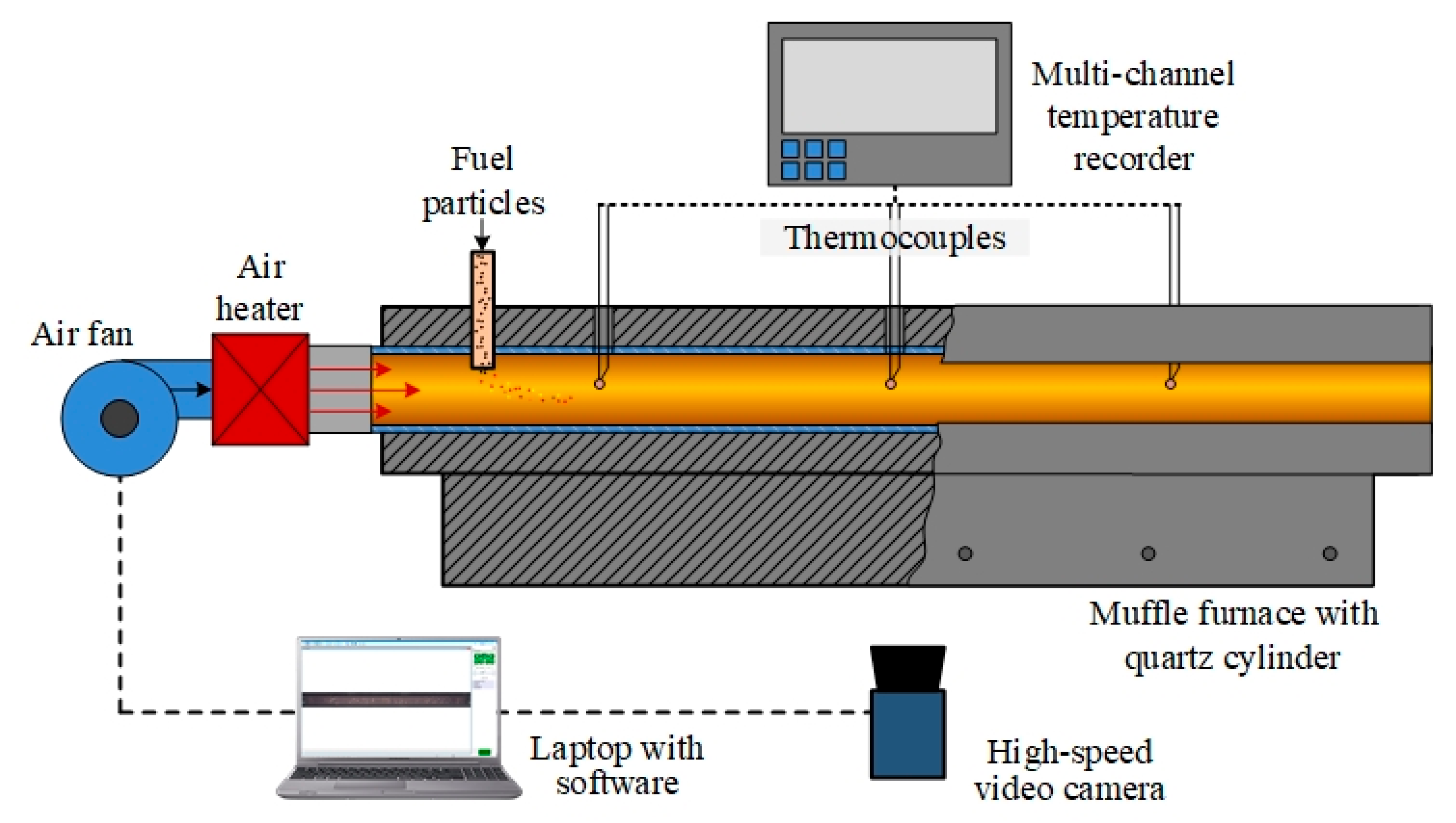
The ignition process of both individual fuels and fuel mixtures was characterized under convective heating conditions on a laboratory bench according to the well-proven methodology [37]. The main components of the bench are a ROBUST high-pressure air fan (LEISTER, Wuppertal, Germany), a LEISTER LE 5000 HT air heater (LEISTER, Wuppertal, Germany), a General Therm RT 1000.1100 SP tube muffle furnace (Nevaterm, Saint Petersburg, Russia), an RMT-59 multi-channel temperature recorder (Elemer, Moscow, Russia), and a V411 high-speed video camera (Vision Research, Wayne, NJ, USA). The scheme of the experimental setup is shown in Figure 2.

Figure 2.
A schematic diagram of the experimental setup for fuel combustion under convective heating conditions.
A ROBUST air fan (LEISTER, Wuppertal, Germany) and a LEISTER LE 5000 HT air heater (LEISTER, Wuppertal, Germany) were used to force a stream of heated air into the quartz cylinder at an air flow velocity of 5 m/s. A General Therm RT 1000.1100 SP tube muffle furnace (Nevaterm, Saint Petersburg, Russia) was used to ensure uniform temperature distribution along the entire length of the quartz cylinder. The temperature of the air stream was recorded using three thermocouples, which were connected to an RMT-59 multi-channel temperature recorder (Elemer, Moscow, Russia). The hot air from the muffle furnace passed through an air cooler and was removed to the atmosphere by exhaust ventilation.
A series of 5–10 experiments were carried out on coal, biomass, and fuel mixtures based on these components, with constant values for the temperature (Ta) of the heated air stream. A fuel portion with a mass of about 5 mg was introduced into the air stream through a ceramic channel. The processes occurring during the movement of finely dispersed solid particles inside the quartz cylinder were recorded using a high-speed color video camera, Phantom V411 (Vision Research, Wayne, NJ, USA), complete with a wide-angle lens, Distagon 1.4/35 ZF.2 T* (Carl Zeiss, Oberkochen, Germany). The automated processing of video recordings to determine td values was performed using the standard Phantom Camera Control 3.0 software (Vision Research, Wayne, NJ, USA) according to the approved methodology [37]. The systematic and random inaccuracies in determining the td times due to the speed of video recording and the scatter of experimental data did not exceed 0.5% and 15%, respectively.
2.4. Experimental Setup for Analyzing Flue Gas Composition
In order to determine the component composition of flue gases, it is necessary to consider the results of the interaction between components in the fuel mixture. Thus, a gas analysis of fuel compositions was carried out using an experimental setup, the scheme of which is shown in Figure 3.
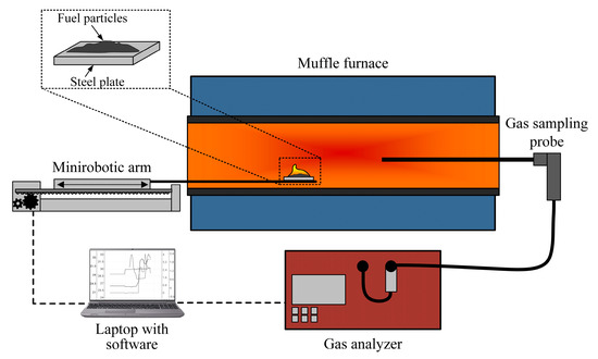
Figure 3.
A schematic diagram of the experimental setup for studying the composition of flue gases during the combustion of fuels.
The combustion of the investigated fuels was carried out in an electric tube muffle furnace, Nabertherm R 50/250/13 (Nabertherm GmbH, Lilienthal, Germany). The composition of flue gases was analyzed using a Test 1gas analyzer (LLC “Bonare”, Novosibirsk, Russia), which is equipped with electrochemical sensors for O2 (range of 0–25%; absolute inaccuracy of ±0.2%), CO (range of 0–40,000 ppm; relative inaccuracy of ±5%), SO2 (range of 0–1000 ppm; relative inaccuracy of ±5%), NO (range of 0–2000 ppm; relative inaccuracy of ±5%), NO2 (range of 0–500 ppm; relative inaccuracy of ±7%), H2S (range of 0–500 ppm; relative inaccuracy of ±5%), and HCl (range of 0–2000 ppm; relative inaccuracy of ±5%). Additionally, the gas analyzer is equipped with optical sensors for CO2 (range of 0–30%; reduced inaccuracy of ±2%), CH4 (range of 0–30%; reduced inaccuracy of ±5%), and CO (range of 0–30%; reduced inaccuracy of ±5%) and a polarographic sensor for H2 (range of 0–5%; absolute inaccuracy of ±5%). The instrument includes a modular probe, condensate collector, and filtration system for drying and purifying the gas sample. A coordinate mechanism, SPSh20-23017/2000Z (CJSC Mechatronic Products Plant, Povarovo, Russia), was used to feed fuel into the combustion chamber, which was controlled via a laptop with specialized software.
During the course of the experiments, the temperature of the control panel of the muffle furnace was maintained at 800 °C. At this temperature, the combustion stages of all used components are stable. After heating the furnace to the set temperature, a 0.2 g fuel sample was fed into the combustion chamber by means of a coordinate mechanism. After introducing the fuel into the furnace, the opening was closed with a dense layer of heat-insulating material. On the reverse side, the modular probe of the gas analyzer was inserted into a similarly sized hole and covered with material. During the process of ignition and combustion, the flue gases flowed through the modular probe into the body of the gas analyzer (passing through the stages of dehydration and filtration), where the concentrations of the gas mixture components were measured. After the conclusion of each experiment, the gas channels and the muffle furnace space were purged with fresh air to remove sample residues. The change in anthropogenic gas concentrations during the combustion process was recorded using Test 1 software (LLC “Bonare”, Novosibirsk, Russia), and within one series, a range of 5 to 10 experiments were performed under identical initial conditions.
3. Results and Discussion
3.1. SEM of Fuel Particles
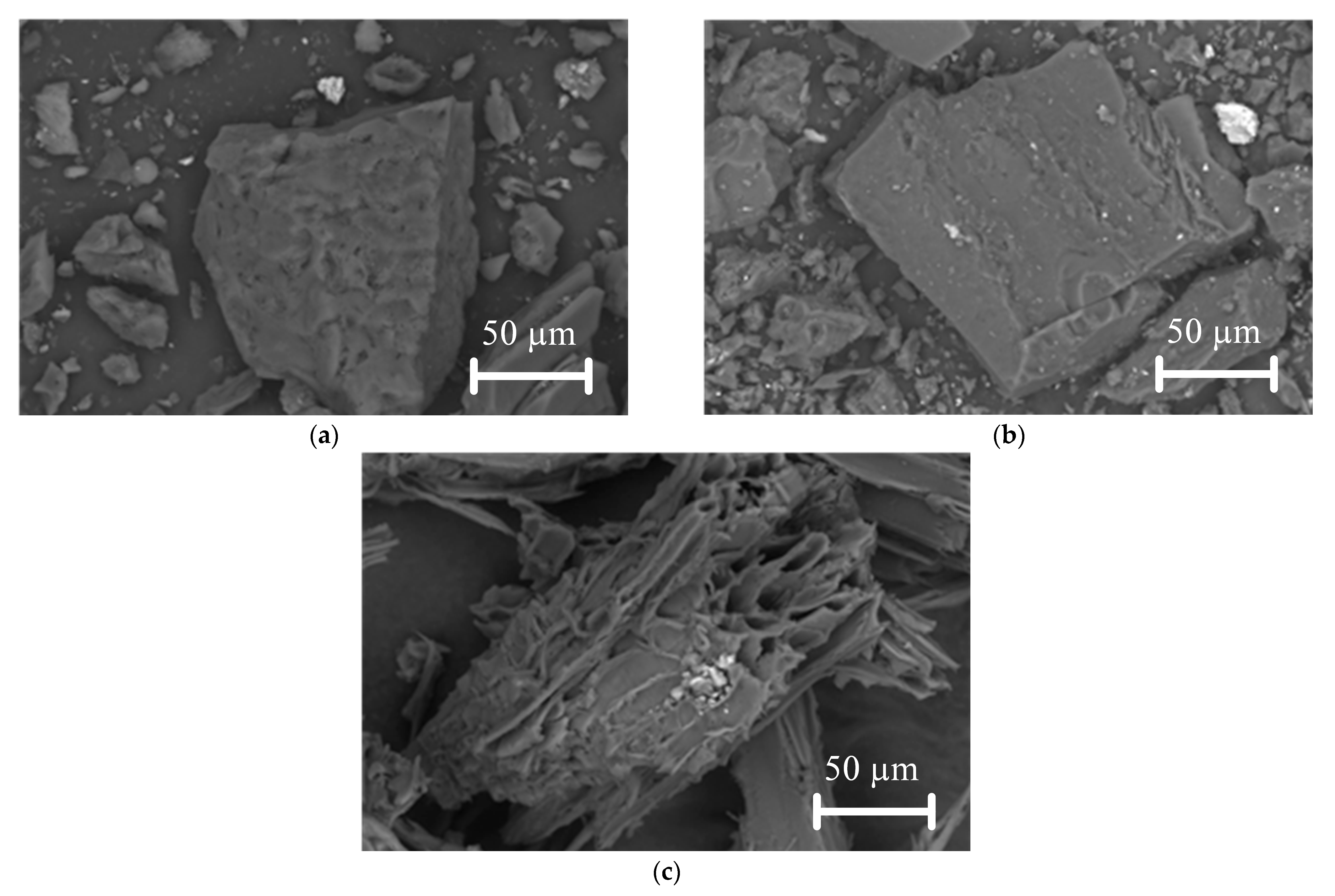
Figure 4 shows scanning electron microscopy (SEM) images of lignite, bituminous coal, and biomass particles.
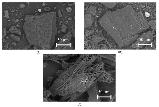
Figure 4.
SEM images of investigated fuels: (a) lignite particles; (b) bituminous coal particles; (c) biomass particles.
As demonstrated in Figure 4, lignite and bituminous coal particles are similar in their geometric shapes. When these particles are enlarged (Figure 4a,b), small pores and cracks become visible on the surface. This is in contrast to the biomass particle, which has a different geometric shape (Figure 4c). The biomass particle itself has large numbers of pores, cracks, and channels (see Figure 4c), which indicate a higher specific surface area of the particles compared to the similar characteristic of coals. The Supplementary Materials presents SEM images (Figure S1) of the studied fuels at different magnifications. The specific surface area of the fuel particle is a key factor influencing the ignition and combustion process because the more carbon in the particle reacts with the oxidizer, the faster it will burn. Through pores, cracks, and channels, the oxidizer penetrates deep into the fuel particle and reacts with the carbon. A qualitative analysis has shown that this characteristic of biomass is higher than that of coal.
3.2. Combustion Process of Individual Fuels and Mixtures in Conductive Heating
Typical frames of videograms of high-speed video recordings of ignition and combustion processes of particles (100–200 μm) of lignite, bituminous coal (Cb and Ch), and biomass (B), as well as their mixtures (CbB-2 and ChB-2), under conductive heating conditions are shown in Figure 5, Figure 6 and Figure 7. The Supplementary Materials presents a series of video frames illustrating the ignition and combustion of fuels with coal and biomass (see Figures S2 and S3).
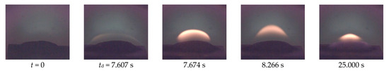
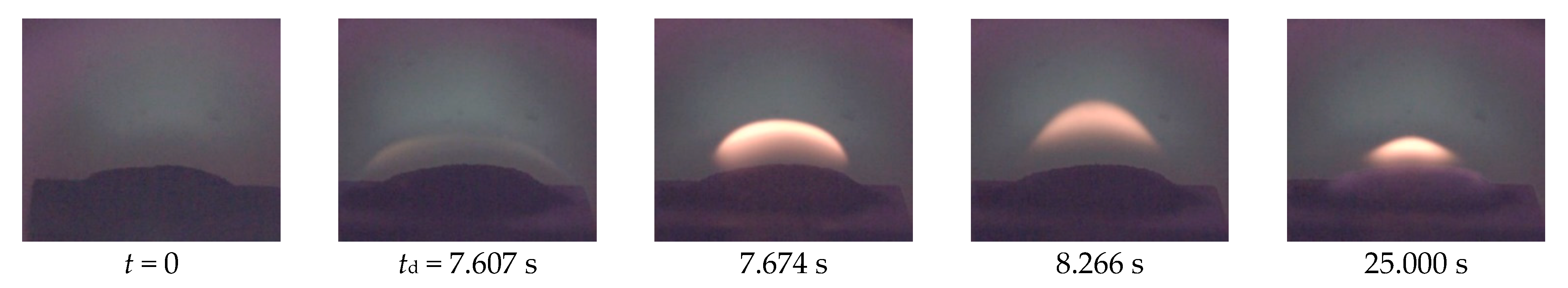
Figure 5.
Video frames of videograms of ignition and combustion of lignite particles (composition Cb) under conditions of conductive heating at Tg = 800 °C.

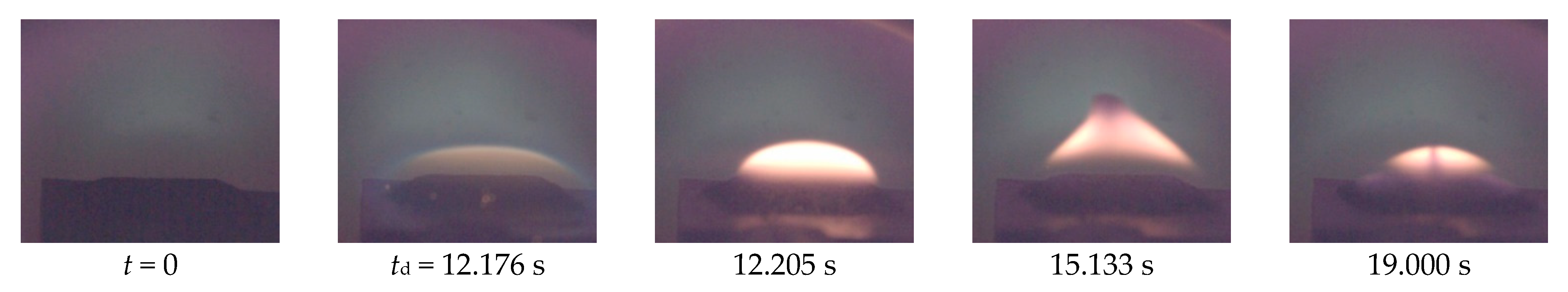
Figure 6.
Video frames of videograms of ignition and combustion of bituminous coal particles (composition Ch) under conditions of conductive heating at Tg = 800 °C.

Figure 7.
Video frames of videograms of ignition and combustion of biomass particles (composition B) under conditions of conductive heating at Tg = 800 °C.
The results reveal that the combustion process of individual fuels and fuel mixtures is characterized by the monotonic burning of fuel particles. Lignite (composition Cb) ignites faster than bituminous coal (composition Ch) due to the higher content of volatile substances (Table 2). Biomass (composition B) demonstrates the shortest ignition delay times (see Figure 7) since it contains less moisture and more volatiles. It is important to note that humidity has a significant effect on combustion characteristics. As the moisture content increases, the heat of combustion and the combustion temperature decrease [38]. This is due to the fact that water absorbs energy during evaporation, which reduces the total heat in the combustion of biomass. Additionally, moisture can inhibit oxygen access to solid fuels, which hinders the combustion process. Moisture can affect the stability of the power plant and the content of harmful emissions; decreasing the moisture content of the fuel increases the temperature in the power plant and its burnout rate [39]. At the same time, the addition of biomass to coal contributes to a decrease in ignition delay times (Figures S2 and S3) due to its higher reactivity [34].
Figure 8 shows the dependences of ignition delay times of (100–200 μm) coal and biomass particles and their mixtures on the oxidizer temperature in the range of 700–1000 °C under conductive heating conditions. The approximation curves are drawn through the points characterizing the average values of ignition delay times (td) of fuel particles established in a series of 5–10 experiments under identical initial conditions.
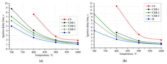
Figure 8.
Dependences of ignition delay times of coal, biomass, and their mixtures on oxidizer temperature under conductive heating conditions: (a) brown coal (Cb), biomass (B), and their mixtures (CbB-1, CbB-2, and CbB-3); (b) bituminous coal (Ch), biomass (B), and their mixtures (ChB-1, ChB-2, and ChB-3).
It is evident that there is an increase in the temperature of the combustion chamber and a decrease in the values of td since at Tg → 1000 °C, the most active processes of heating, moisture vaporization, and volatile release in the fuel particles occur. The minimum temperature required for stable gas-phase ignition of a 0.04 g fuel particle suspension on a metal surface is 700 °C. At this temperature, the difference in ignition delay times for different fuel compositions is quite significant (up to 5 s). It is worth noting that coal particles (compositions Cb and Ch) are ignited at temperatures exceeding 800 °C (Figure 8). This is due to the fact that the concentration of combustible substances in their vicinity at lower temperatures is insufficient to realize the gas-phase ignition. At the same time, the addition of biomass contributes not only to the reduction in ignition delay times, but also to the ignition of fuel mixtures at temperatures below 800 °C (Figure 8). The results show that the addition of biomass (10–30 wt.%) to lignite and bituminous coal reduces the ignition delay times by 34–66% (Figure 8a) and 36–78% (Figure 8b), respectively (at temperatures of 800–1000 °C).
3.3. Combustion Process of Fuels and Fuel Mixtures Under Convective Heating
Typical frames of high-speed video recordings of the ignition and combustion of particles (100–200 μm) of lignite, bituminous coal (Cb, Ch), and biomass (B) as well as their mixtures (CbB-2, ChB-2) under convective heating conditions are shown in Figure 9, Figure 10 and Figure 11. Video frames were obtained with a step ∆t = 0.10 s from the moment of fuel ignition. The Supplementary Materials presents typical video frames of the ignition and combustion of fuels with coal and biomass (see Figures S4 and S5).
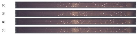
Figure 9.
Video frames of videograms of ignition and combustion of lignite particles (composition Cb) under conditions of movement in flow of heated air at Ta = 700 °C (Δt = 0.01 s): (a) td = 0.052 s; (b) t = td + ∆t; (c) t = td + 2∆t; (d) t = td + 3∆t.

Figure 10.
Video frames of videograms of ignition and combustion of bituminous coal particles (composition Ch) under conditions of motion in flow of heated air at Ta = 700 °C (Δt = 0.01 s): (a) td = 0.095 s; (b) t = td + ∆t; (c) t = td + 2∆t; (d) t = td + 3∆t.
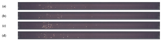
Figure 11.
Video frames of videograms of ignition and combustion of biomass particles (composition B) under conditions of motion in flow of heated air at Ta = 700 °C (Δt = 0.01 s): (a) td = 0.030 s; (b) t = td + ∆t; (c) t = td + 2∆t; (d) t = td + 3∆t.
The results show (see Figure 9 and Figure 10) that lignite and bituminous coal individually ignite over longer periods than other compositions (fuel mixtures), with bituminous coal (composition Ch) characterized by the longest ignition delay times and lower burnout completeness. In contrast, biomass (composition B) has shorter ignition delay times (Figure 11), which is explained by the presence of pores, cracks, and channels on the surfaces of the particles (Figure 4c) as well as the lowest moisture content and the highest content of volatile components (Table 2). The combustion of coal and biomass not only allows for the ignition delay times to be reduced (compared to coal in initial state), but also the completeness of fuel burnout to be increased (Figures S4 and S5).
Figure 12 illustrates the dependences of the ignition delay times of coal and biomass particles (100–200 μm) and their mixtures on the oxidant temperature in the range of 500–800 °C when fine fuel particles move in a flow of heated air. The approximation curves are drawn through the points characterizing the average values of ignition delay times (td) of fuel particles established in a series of 5–10 experiments under identical initial conditions.
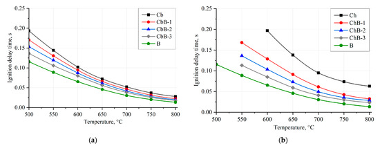
Figure 12.
Dependences of ignition delay times of coal, biomass, and their mixtures on oxidant temperature under convective heating conditions: (a) brown coal (Cb), biomass (B), and their mixtures (CbB-1, CbB-2, and CbB-3); (b) bituminous coal (Ch), biomass (B), and their mixtures (ChB-1, ChB-2, and ChB-3).
Coal (compositions Cb and Ch), in contrast to biomass (composition B), requires more energy (and, consequently, time at Ta = const) to ignite heterogeneous combustion due to the fact that coal has a dense structure, mainly with closed pores, compared to biomass (Figure 4). The higher the value of Vdaf, the shorter the ignition delay time of the corresponding fuel under other identical conditions. The difference in ignition delay times between lignite and bituminous coal and biomass is up to 40% and 70%, respectively, in the whole range of heated air temperatures (500–800 °C). It is important to note that the addition of even 10 wt.% of biomass to bituminous coal intensifies its ignition process at lower temperatures (Figure 12b). Furthermore, when biomass (10–30 wt.%) is added to lignite and bituminous coal, the ignition delay times (when Ta is changed from 500 to 800 °C) are reduced by 19–37% and 34–63%, respectively, compared to the coals in the initial state. Thus, biomass can be used as an additive to intensify the ignition and combustion processes of solid fossil fuels, such as lignite and bituminous coal.
3.4. Analysis of Gaseous Emissions During Combustion of Fuels and Fuel Mixtures
As illustrated in Figure 13 and Figure 14, the average values of the anthropogenic gas concentrations were measured during the combustion of coal, biomass, and their mixtures in a tubular muffle furnace at 800 °C (see Figure 3).

Figure 13.
Composition of flue gases during combustion of lignite (Cb), biomass (B), and their mixtures (CbB-1, CbB-2, and CbB-3) at 800 °C: (a) CO and CO2; (b) NOx and SOx.
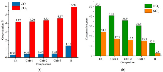
Figure 14.
Composition of flue gases during combustion of bituminous coal (Ch), biomass (B), and their mixtures (CbB-1, CbB-2, and CbB-3) at 800 °C: (a) CO and CO2; (b) NOx and SOx.
The combustion of coal (compositions Cb and Ch) has been found to emit less CO and CO2 than the combustion of biomass (composition B) (Figure 13a and Figure 14a). Furthermore, when biomass is added to lignite (10 to 30%), the average concentration of carbon dioxide increases by 5.2–8.2%, and that of carbon monoxide by 10.7–39.3% (see Figure 13a). And when biomass is added to bituminous coal, the average concentration of carbon dioxide increases by 0.7–9.6%, and that of carbon monoxide by 12.5–37.5% (Figure 14a). The obtained results can be explained as follows: After the beginning of the heating of lignite (composition Cb) and bituminous coal (composition Ch), the concentration of carbon dioxide increases sharply (the maximum value does not exceed 20%), reaches its peak, and begins to decrease monotonically due to the afterburning of coke residue. In biomass combustion (composition B), the decrease in the CO2 concentration occurs as fast as its increase, and the maximum value does not exceed 40%. Therefore, the average value of the carbon dioxide concentration over the whole interval of its formation is higher in the case of biomass combustion. A similar pattern of concentration change occurs for carbon monoxide, CO.
As demonstrated in Figure 13b and Figure 14b, an increase in the share of biomass in the fuel mixture leads to a decrease in NOx concentrations. It should be noted that the addition of even a small amount of biomass (10%) to coal contributes to the reduction in the NOx concentration by 18.7–21.1%. Biomass does not contain nitrogenous compounds in its composition (Table 2) when compared to lignite (Ndaf = 0.9%) and bituminous coal (Ndaf = 2.1%). CbB-3 and ChB-3 mixtures (biomass content 30%) emit 41.5% and 38.9% less nitrogen oxides, respectively, during combustion when compared to the coals in the initial state. The combustion of coal has been shown to produce high levels of NOx, a consequence of the following reactions [40]: O + N2 → NO + N; N + O2 → NO + O; N + OH → NO + H.
The highest concentrations of sulphur oxides in combustion products are observed in coals, with that of lignite being 20.9 ppm (Figure 13b) and that of bituminous coal being 24.5 ppm (Figure 14b). This is due to the fact that coals contain more sulphur in their composition compared to biomass (see Table 2). When biomass is added to lignite, the concentration of sulphur oxides in flue gases is reduced by 24–39%, and when added to bituminous coal, it is reduced by 29–38% compared to the initial coals (compositions Cb and Ch, respectively).
3.5. Tendency of Fuels to Undergo Slagging
Slagging leads to the formation of deposits on heating surfaces. This reduces the efficiency of boiler equipment operation and increases the risk of accidents. The study of slagging properties of fuels allows for methods of slagging control and to be developed and furnace parameters to be optimized. Table 3 presents the results of determining the percentage content of basic oxides in the mineral part of lignite, bituminous coal, and biomass.
Table 3.
Contents of basic oxides in ashes of investigated fuels.
Mineral particles of coal (lignite and bituminous coal) contain more oxides of silicon, aluminum, and iron than particles of biomass, which are primarily represented by calcium and potassium oxides (see Table 3). The influence of the content of these trace elements in coal ash and biomass on the contamination of heating surfaces of power plants was determined according to the typical methodology [41,42,43,44,45,46,47,48,49,50,51], including the following criteria: an assessment of the ratio of basic and acid compounds; an assessment of the tendency to undergo layer agglomeration (in the case of layer combustion); and an assessment of the tendency to increase slag viscosity (silica deposits).
The ratio of basic to acidic compounds (B/A) is found by the following expression:
B/A = (Fe2O3 + CaO + MgO + Na2O + K2O)/(SiO2 + Al2O3 + TiO2)
The tendency of ash to undergo slagging increases with an increasing B/A ratio. The ash is considered to have a low tendency to undergo slagging at B/A < 0.5, medium tendency at 0.5 < B/A < 1, high tendency at 1 < B/A < 1.75, and very high tendency at a B/A ratio above 1.75.
The layer agglomeration index for layer combustion is determined by the following expression:
BAI = Fe2O3/(Na2O + K2O)
It has been established that a high tendency to undergo layer agglomeration occurs when BAI < 0.15.
The propensity of slag to deposit on the grate at layer combustion or flaring with liquid slag removal (Sr) is determined by the following expression:
Sr = (SiO2/(SiO2 + Fe2O3 + CaO + MgO))×100
The low rank of Sr corresponds to values greater than 72, with the medium rank corresponding to values ranging from 65 to 72, and the high rank to values below 65.
The results of the analysis obtained by calculation according to Formulas 1–3 are presented in Table 4.
Table 4.
Analysis of tendency of fuels to contaminate heating surfaces.
The high contents of silicon oxides, iron oxides, and aluminum oxides in coals are the main reason for the tendency to undergo fouling in heating surfaces. In contrast, the tendency to undergo layer agglomeration is ranked low for coals and high for biomass. Biomass ash is mainly represented by calcium and potassium oxide, so it has a high tendency not only to contaminate heating surfaces in the boiler furnace, but also to undergo layer agglomeration during layer combustion. The addition of up to 30% of biomass to coal has no effect on reducing the propensity of heating surfaces to slagging, does not pose a threat to layer agglomeration in the layer combustion of mixtures, and has a high propensity to silica deposits (Table 4).
4. Practical Application
In order to choose a technology for the co-combustion of coal and biomass, detailed studies are necessary. A well-founded decision cannot be made without analyzing the whole cycle, from the biomass source and its characteristics to the possibilities and requirements of electricity and heat supply. The decisive influences on economic efficiency are the type of biomass (elemental analysis), the available biomass volumes (which determine the size of the plant), the total price of biomass (including future forecasts), and the total costs of the plant (investment costs, plant operation costs, environmental costs, etc.).
As illustrated in Figure 15a, a furnace for the layer combustion of a solid fuel mixture is used, with the fuel being fed from a common fuel hopper by feeders to the grate. The most suitable combustion devices are fluidized bed (FBC) and circulating fluidized bed (CFB) boiler furnaces. The advantage of CFB is the possibility of the combustion of low calorific fuel with high moisture and ash contents; the use of technology for partial SOx removal is achieved by adding limestone to the fluidized bed. The transition to the combustion of solid fuel mixtures does not require significant capital investments while ensuring high boiler efficiency and low emissions of nitrogen oxides.
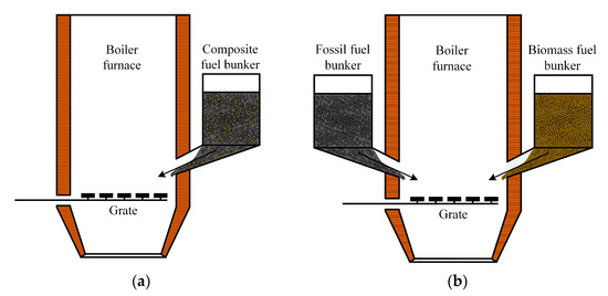
Figure 15.
Boiler furnace for layer combustion of solid fuel mixtures: (a) with one fuel bunker; (b) with two fuel bunkers.
The most practical way to achieve the layer combustion of solid fuel mixtures is by using boilers equipped with separate fuel hoppers. Figure 15b shows an example of a boiler furnace equipped with two fuel bunkers and a grate. In this case, the fuels from the warehouse are fed by different belt conveyors to separate fuel hoppers and further to the boiler. No special fuel preparation is required, and the required ratio of components in the solid fuel mixture is achieved inside the boiler furnace by adjusting the fuel feeders. The area of application of this technology, high-moisture waste with a significant share of coarse fractions (lump waste), cannot be thermally processed in other types of furnace devices.
Flared combustion boilers (Figure 16) require additional fuel preparation. This technology is not suitable for the combustion of lump waste. In wood processing plants, the shredding of all lump wood waste is required, which can exceed 50% of the total amount. And wet waste also requires drying before shredding. In the case that the solid fuel mixture is suitable for grinding in existing milling units, coal and biomass are fed to the fuel preparation system and then to the dust hopper, from which the mixture is fed to the boiler furnace by dust feeders (Figure 16a). It is also possible to use milling devices, which, after grinding the solid fuel mixture, feed the fuel to the boiler burners.
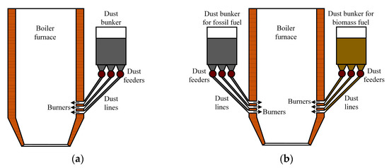
Figure 16.
Boiler furnace for flaring combustion of solid fuel mixture: (a) with single common fuel bunker; (b) with two fuel bunkers.
In the case that the fuel store is not equipped with the above-mentioned equipment or the milling plants are not suitable for biomass milling, the fuel can be supplied to the boiler house from the store by different belt conveyors (with coal and biomass being conveyed separately). In such cases, the fuel components are mixed inside the boiler furnace and fed by dust feeders from separate fuel hoppers (Figure 16b). The particle size of fine fuel at flare combustion should not exceed 250 µm.
In the context of flaring solid fuel mixtures, it is desirable to use boilers that are equipped with a device for low-temperature swirl combustion (Figure 17). The implementation of vortex combustion furnaces allows for biomass to be burned together with coal despite the differences in the structure and shape of fuel particles.
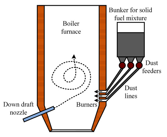
Figure 17.
Flare combustion boiler furnace equipped with down draft nozzle.
The co-combustion of coal and biomass is a strategy to improve the overall efficiency of boilers based on traditional fossil fuels. This approach not only reduces the carbon footprint by reducing the dependence on fossil energy sources, but also optimizes the calorific value of the fuel. The results of the studies show that the combustion of coal and biomass together reduces NOx and SOx emissions. The combustion of biomass has been shown to have a combined combustion effect, which can significantly improve the thermodynamic characteristics of the process and contribute to a more complete combustion of coal. Different heat input methods (convective and conductive) have been found to reduce the ignition delay times of coal and biomass fuels. The optimal ratio of biomass to coal has been demonstrated to improve boiler efficiency and minimize the formation of ash and other harmful combustion by-products. Furthermore, the addition of up to 30% of biomass to coal has been found to have no significant effect on the tendency of such fuels to undergo slagging. Thus, the integration of biomass into coal-fired boilers is an effective approach to modernizing energy systems to reduce the consumption of fossil fuels and the environmental impact of harmful emissions.
The results of this study confirm that the idea of coal and biomass combustion holds significant interest both for science and practical application. The use of biomass as an additive to solid fossil fuels has the potential to reduce consumption, improve environmental performance, and optimize combustion characteristics. CFD modeling based on the results obtained can give an idea of the processes occurring in boiler furnaces during the combustion of coal and biomass.
5. Conclusions
As a result of the experimental studies conducted on particles of lignite and bituminous coal, biomass, and mixtures based on them, the characteristics of ignition and combustion processes at different methods of heat supply (conductive and convective), the tendency of fuels to undergo slagging, and the composition of flue gases were determined. Under the conditions of conductive heating, the ignition delay times of fuels at varying oxidizer temperatures in the range of 700–1000 °C, which vary from 1 to 12.2 s, were determined. For convective heating (air flow temperature of 500–800 °C), the ignition delay times vary from 0.01 to 0.19 s. The addition of biomass to coal leads to an improvement in the ecological characteristics of the combustion process without the significant deterioration of energy characteristics. The flue gas composition analysis revealed CO, CO2, NOx, and SOx contents in the combustion of lignite (0.28%, 4.63%, 46.00 ppm, and 20.90 ppm, respectively), bituminous coal (0.32%, 4.17%, 50.40 ppm, and 24.50 ppm, respectively) and biomass (1.37%, 5.92%, 12.80 ppm, and 2.50 ppm, respectively). The presence of large numbers of large pores, channels, and cracks in biomass particles in contrast to coal was revealed by SEM analysis. This has a positive effect on the intensification of biomass ignition and combustion processes. At the same time, due to the high contents of calcium and potassium oxides in biomass ash, there is a high tendency not only to contaminate heating surfaces in the boiler furnace, but also to undergo layer agglomeration in layer combustion.
Following thorough examinations of the fuel mixtures under consideration, it was determined that those comprising up to 20 wt.% biomass in conjunction with bituminous coal exhibited the greatest potential for practical implementation along with the prevalent solid natural fuels. They provide the lowest tendency to contaminate heating surfaces in boiler furnaces among the considered fuels. The addition of 20 wt.% of biomass to bituminous coal has been shown to reduce the delay times of particles’ ignition during conductive heating by 53–70% and during convective heating in the flow of heated air by 47–52%. Furthermore, the contents of nitrogen oxides and sulphur oxides in flue gases are reduced by 29% and 34%, respectively.
Supplementary Materials
The following supporting information can be downloaded at https://www.mdpi.com/article/10.3390/fire8030106/s1, Figure S1: SEM images of studied fuels; Figure S2: Video frames of videograms of ignition and combustion of biomass particles (composition CbB-2) under conditions of conductive heating at Tg = 800 °C; Figure S3: Video frames of videograms of ignition and combustion of biomass particles (composition ChB-2) under conditions of conductive heating at Tg = 800 °C; Figure S4: Video frames of videograms of ignition and combustion of lignite and biomass-based fuel mixture particles (composition CbB-2) under conditions of motion in flow of heated air at Ta = 700 °C (Δt = 0.01 s); Figure S5: Video frames of videograms of ignition and combustion of particles of bituminous coal and biomass fuel mixture (composition ChB-2) under conditions of motion in flow of heated air at Ta = 700 °C (Δt = 0.01 s).
Author Contributions
Conceptualization, A.Z., D.G. and A.P.; methodology, A.P.; software, S.C.; validation, D.G. and A.Z; formal analysis, I.G.; investigation, A.P.; resources, A.Z.; data curation, A.Z.; writing—original draft preparation, A.P.; writing—review and editing, A.P., A.Z. and I.G.; visualization, D.G.; supervision, A.Z.; project administration, A.Z. All authors have read and agreed to the published version of the manuscript.
Funding
This research was supported by the Russian Science Foundation [grant number 23-23-00280; URL (accessed on 29 January 2025): https://rscf.ru/en/project/23-23-00280/].
Institutional Review Board Statement
Not applicable.
Informed Consent Statement
Not applicable.
Data Availability Statement
The data presented in this study are available upon request from the corresponding author. The data are not publicly available due to confidentiality reasons.
Conflicts of Interest
The authors declare no conflicts of interest.
References
- Filonchyk, M.; Peterson, M.P.; Zhang, L.; Hurynovich, V.; He, Y. Greenhouse gases emissions and global climate change: Examining the influence of CO2, CH4, and N2O. Sci. Total Environ. 2024, 935, 173359. [Google Scholar] [CrossRef] [PubMed]
- Hou, H.; Lu, W.; Liu, B.; Hassanein, Z.; Mahmood, H.; Khalid, S. Exploring the Role of Fossil Fuels and Renewable Energy in Determining Environmental Sustainability: Evidence from OECD Countries. Sustainability 2023, 15, 2048. [Google Scholar] [CrossRef]
- Paramati, S.R.; Shahzad, U.; Doğan, B. The role of environmental technology for energy demand and energy efficiency: Evidence from OECD countries. Renew. Sustain. Energy Rev. 2022, 153, 111735. [Google Scholar] [CrossRef]
- Autelitano, K.; Famiglietti, J.; Aprile, M.; Motta, M. Towards Life Cycle Assessment for the Environmental Evaluation of District Heating and Cooling: A Critical Review. Standards 2024, 4, 102–132. [Google Scholar] [CrossRef]
- Chu, W.; Vicidomini, M.; Calise, F.; Duić, N.; Østergaard, P.A.; Wang, Q.; da Graça Carvalho, M. Recent Advances in Low-Carbon and Sustainable, Efficient Technology: Strategies and Applications. Energies 2022, 15, 2954. [Google Scholar] [CrossRef]
- Si, M.; Liu, J.; Zhang, Y.; Liu, B.; Luo, Z.; Cheng, Q. Effect of co-combustion of coal with biomass on the morphology of soot. Renew. Energy 2024, 226, 120374. [Google Scholar] [CrossRef]
- Yuan, Y.; Zuo, H.; Wang, J.J.; Gao, Y.; Xue, Q.; Wang, J.J. Co-combustion behavior, kinetic and ash melting characteristics analysis of clean coal and biomass pellet. Fuel 2022, 324, 124727. [Google Scholar] [CrossRef]
- Adeleke, A.A.; Ikubanni, P.P.; Emmanuel, S.S.; Fajobi, M.O.; Nwachukwu, P.; Adesibikan, A.A.; Odusote, J.K.; Adeyemi, E.O.; Abioye, O.M.; Okolie, J.A. A comprehensive review on the similarity and disparity of torrefied biomass and coal properties. Renew. Sustain. Energy Rev. 2024, 199, 114502. [Google Scholar] [CrossRef]
- Liu, L.; Memon, M.Z.; Xie, Y.; Gao, S.; Guo, Y.; Dong, J.; Gao, Y.; Li, A.; Ji, G. Recent advances of research in coal and biomass co-firing for electricity and heat generation. Circ. Econ. 2023, 2, 100063. [Google Scholar] [CrossRef]
- Sahu, S.G.; Chakraborty, N.; Sarkar, P. Coal–biomass co-combustion: An overview. Renew. Sustain. Energy Rev. 2014, 39, 575–586. [Google Scholar] [CrossRef]
- Baxter, L. Biomass-Coal Cofiring: An Overview of Technical Issues. In Solid Biofuels for Energy: A Lower Greenhouse Gas Alternative; Springer: Berlin/Heidelberg, Germany, 2011; pp. 43–73. [Google Scholar] [CrossRef]
- Yi, B.; Chen, M.; Gao, Y.; Cao, C.; Wei, Q.; Zhang, Z.; Li, L. Investigation on the co-combustion characteristics of multiple biomass and coal under O2/CO2 condition and the interaction between different biomass. J. Environ. Manag. 2023, 325, 116498. [Google Scholar] [CrossRef] [PubMed]
- Xu, L.; Zhu, G.; Niu, Y. Effect of preheating Co-firing of biomass and coal on the synergistic reduction of PM and NO source emissions. J. Clean. Prod. 2023, 414, 137562. [Google Scholar] [CrossRef]
- Yang, X.; Song, G.; Li, Z.; Song, Q. Effect of biomass-coal blending combustion on Pb transformation. J. Hazard. Mater. 2024, 461, 132697. [Google Scholar] [CrossRef]
- Du, S.; Wang, J.; Yu, Y.; Zhou, Q. Coarse-grained CFD-DEM simulation of coal and biomass co-gasification process in a fluidized bed reactor: Effects of particle size distribution and operating pressure. Renew. Energy 2023, 202, 483–498. [Google Scholar] [CrossRef]
- Chaiyo, R.; Wongwiwat, J.; Sukjai, Y. Numerical and Experimental Investigation on Combustion Characteristics and Pollutant Emissions of Pulverized Coal and Biomass Co-Firing in a 500 kW Burner. Fuels 2025, 6, 9. [Google Scholar] [CrossRef]
- Yang, X.; Zhao, Z.; Zhao, Y.; Xu, L.; Feng, S.; Wang, Z.; Zhang, L.; Shen, B. Effects of torrefaction pretreatment on fuel quality and combustion characteristics of biomass: A review. Fuel 2024, 358, 130314. [Google Scholar] [CrossRef]
- Dula, M.; Kraszkiewicz, A. Theory and Practice of Burning Solid Biofuels in Low-Power Heating Devices. Energies 2025, 18, 182. [Google Scholar] [CrossRef]
- Wang, X.; Xu, J.; Ling, P.; An, X.; Han, H.; Chen, Y.; Jiang, L.; Wang, Y.; Su, S.; Hu, S.; et al. A study on the release characteristics and formation mechanism of SO2 during co-combustion of sewage sludge and coal slime. Fuel 2023, 333, 126511. [Google Scholar] [CrossRef]
- Wang, X.; Luo, Z.; Wang, Y.; Zhu, P.; Wang, S.; Wang, K.; Yu, C. NO emission during the co-combustion of biomass and coal at high temperature: An experimental and numerical study. J. Energy Inst. 2024, 115, 101707. [Google Scholar] [CrossRef]
- Hariana; Putra, H.P.; Prabowo; Hilmawan, E.; Darmawan, A.; Mochida, K.; Aziz, M. Theoretical and experimental investigation of ash-related problems during coal co-firing with different types of biomass in a pulverized coal-fired boiler. Energy 2023, 269, 126784. [Google Scholar] [CrossRef]
- Roy, R.; Schooff, B.; Li, X.; Montgomery, S.; Tuttle, J.; Wendt, J.O.L.; Dickson, K.; Iverson, B.; Fry, A. Ash aerosol particle size distribution, composition, and deposition behavior while co-firing coal and steam-exploded biomass in a 1.5 MWth combustor. Fuel Process. Technol. 2023, 243, 107674. [Google Scholar] [CrossRef]
- Karuana, F.; Prismantoko, A.; Suhendra, N.; Darmawan, A.; Hariana, H.; Darmadi, D.B.; Akhsin Muflikhun, M. Investigation of austenitic stainless steel corrosion resistance against ash deposits from co-combustion coal and biomass waste. Eng. Fail. Anal. 2023, 150, 107368. [Google Scholar] [CrossRef]
- Mo, W.; Du, K.; Sun, Y.; Guo, M.; Zhou, C.; You, M.; Xu, J.; Jiang, L.; Wang, Y.; Su, S.; et al. Technical-economic-environmental analysis of biomass direct and indirect co-firing in pulverized coal boiler in China. J. Clean. Prod. 2023, 426, 139119. [Google Scholar] [CrossRef]
- Fakourian, S.; Roberts, M.; Dai, J. Numerical prediction of ash deposit growth burning pure coal and its blends with woody biomass in a 1.5 MWTH combustor. Appl. Therm. Eng. 2023, 224, 120110. [Google Scholar] [CrossRef]
- Lee, D.-G.; Lee, J.-H.; Kim, G.-M.; Jeong, J.-S.; Kim, S.-M.; Jeon, C.-H. The Initial ash deposition formation in horizontal combustion reactor for blending torrefied biomass wood pellets and coals. Renew. Energy 2024, 226, 120198. [Google Scholar] [CrossRef]
- Díez, L.I.; García-Mariaca, A.; Llera-Sastresa, E.; Canalís, P. On the oxy-combustion of blends of coal and agro-waste biomass under dry and wet conditions. Fuel 2024, 365, 131265. [Google Scholar] [CrossRef]
- Liu, Q.; Zhong, W.; Yu, A.; Wang, C.-H. Modelling the co-firing of coal and biomass in a 10 kWth oxy-fuel fluidized bed. Powder Technol. 2022, 395, 43–59. [Google Scholar] [CrossRef]
- Tabet, F.; Gökalp, I. Review on CFD based models for co-firing coal and biomass. Renew. Sustain. Energy Rev. 2015, 51, 1101–1114. [Google Scholar] [CrossRef]
- Chen, J.; Zhong, S.; Li, D.; Zhao, C.; Han, C.; Yu, G.; Song, M. Effect of the blend ratio on the co-gasification of biomass and coal in a bubbling fluidized bed with CFD-DEM. Int. J. Hydrogen Energy 2022, 47, 22328–22339. [Google Scholar] [CrossRef]
- Wang, X.; Li, X.; Yi, L.; Lyngfelt, A.; Mattisson, T.; Wu, X.; Luo, H.; Xiong, Q. CFD modeling of a fluidized bed with volatiles distributor for biomass chemical looping combustion. Chem. Eng. Sci. 2024, 295, 120211. [Google Scholar] [CrossRef]
- Dong, L.; Alexiadis, A. Simulation of char burnout characteristics of biomass/coal blend with a simplified single particle reaction model. Energy 2023, 264, 126075. [Google Scholar] [CrossRef]
- Al-Naiema, I.; Estillore, A.D.; Mudunkotuwa, I.A.; Grassian, V.H.; Stone, E.A. Impacts of co-firing biomass on emissions of particulate matter to the atmosphere. Fuel 2015, 162, 111–120. [Google Scholar] [CrossRef]
- Glushkov, D.O.; Zhuikov, A.V.; Nurpeiis, A.E.; Paushkina, K.K.; Kuznechenkova, D.A. Ignition behavior of a mixture of brown coal and biomass during the movement of fine particles in a hot air flow. Fuel 2024, 363, 131010. [Google Scholar] [CrossRef]
- Romanov, D.S.; Vershinina, K.Y.; Dorokhov, V.V.; Strizhak, P.A. Rheology, ignition, and combustion performance of coal-water slurries: Influence of sequence and methods of mixing. Fuel 2022, 322, 124294. [Google Scholar] [CrossRef]
- Feoktistov, D.V.; Glushkov, D.O.; Kuznetsov, G.V.; Nikitin, D.S.; Orlova, E.G.; Paushkina, K.K. Ignition and combustion characteristics of coal-water-oil slurry placed on modified metal surface at mixed heat transfer. Fuel Process. Technol. 2022, 233, 107291. [Google Scholar] [CrossRef]
- Glushkov, D.; Zhuikov, A.; Zemlyansky, N.; Pleshko, A.; Fetisova, O.; Kuznetsov, P. Influence of the Composition and Particle Sizes of the Fuel Mixture of Coal and Biomass on the Ignition and Combustion Characteristics. Appl. Sci. 2023, 13, 11060. [Google Scholar] [CrossRef]
- Al-qazzaz, A.; Eidgah, E.E.F.; Alfatlawi, A.-W.; Masroori, A.; Abed, A.M.; Ajam, H.; Kianifar, A. An approach of analyzing gas and biomass combustion: Positioned of flame stability and pollutant reduction. Results Eng. 2024, 23, 102823. [Google Scholar] [CrossRef]
- Liang, D.; Li, Y.; Zhou, Z. Numerical Study of Thermochemistry and Trace Element Behavior during the Co-Combustion of Coal and Sludge in Boiler. Energies 2022, 15, 888. [Google Scholar] [CrossRef]
- Radwan, A.M.; Paul, M.C. Plasma assisted NH3 combustion and NOx reduction technologies: Principles, challenges and prospective. Int. J. Hydrogen Energy 2024, 52, 819–833. [Google Scholar] [CrossRef]
- Lachman, J.; Baláš, M.; Lisý, M.; Lisá, H.; Milčák, P.; Elbl, P. An overview of slagging and fouling indicators and their applicability to biomass fuels. Fuel Process. Technol. 2021, 217, 106804. [Google Scholar] [CrossRef]
- Yao, X.; Xu, K.; Yan, F.; Liang, Y. The Influence of Ashing Temperature on Ash Fouling and Slagging Characteristics during Combustion of Biomass Fuels. BioResources 2017, 12, 1593–1610. [Google Scholar] [CrossRef]
- Chen, C.; Bi, Y.; Huang, Y.; Huang, H. Review on slagging evaluation methods of biomass fuel combustion. J. Anal. Appl. Pyrolysis 2021, 155, 105082. [Google Scholar] [CrossRef]
- Suyatno, S.; Hariana, H.; Prismantoko, A.; Prida Putra, H.; Mayang Sabrina Sunyoto, N.; Darmawan, A.; Ghazidin, H.; Aziz, M.; Putra, H.P.; Mayang, N.; et al. Assessment of potential tropical woody biomass for coal co-firing on slagging and fouling aspects. Therm. Sci. Eng. Prog. 2023, 44, 102046. [Google Scholar] [CrossRef]
- Wang, Y.; Qin, Y.; Vassilev, S.V.; He, C.; Vassileva, C.G.; Wei, Y. Migration behavior of chlorine and sulfur during gasification and combustion of biomass and coal. Biomass Bioenergy 2024, 182, 107080. [Google Scholar] [CrossRef]
- Teixeira, P.; Lopes, H.; Gulyurtlu, I.; Lapa, N.; Abelha, P. Slagging and Fouling during Coal and Biomass Cofiring: Chemical Equilibrium Model Applied to FBC. Energy Fuels 2014, 28, 697–713. [Google Scholar] [CrossRef]
- Kleinhans, U.; Wieland, C.; Frandsen, F.J.; Spliethoff, H. Ash formation and deposition in coal and biomass fired combustion systems: Progress and challenges in the field of ash particle sticking and rebound behavior. Prog. Energy Combust. Sci. 2018, 68, 65–168. [Google Scholar] [CrossRef]
- Vassilev, S.V.; Baxter, D.; Vassileva, C.G. An overview of the behaviour of biomass during combustion: Part I. Phase-mineral transformations of organic and inorganic matter. Fuel 2013, 112, 391–449. [Google Scholar] [CrossRef]
- Zhou, H.; Xu, K.; Yao, X.; Li, J. Mineral transformations and molten mechanism during combustion of biomass ash. Renew. Energy 2023, 216, 119113. [Google Scholar] [CrossRef]
- Miles, T.R.; Miles, T.R.; Baxter, L.L.; Bryers, R.W.; Jenkins, B.M.; Oden, L.L. Boiler deposits from firing biomass fuels. Biomass Bioenergy 1996, 10, 125–138. [Google Scholar] [CrossRef]
- Ma, P.; Li, B.; Diao, R.; Liu, X.; Cheng, Z.; Qi, F. Demineralization effects on physicochemical and combustion characteristics of biomass: Insights into distributed kinetics, flue gas evolution, and slag formation. Fuel 2024, 370, 131836. [Google Scholar] [CrossRef]


Disclaimer/Publisher’s Note: The statements, opinions and data contained in all publications are solely those of the individual author(s) and contributor(s) and not of MDPI and/or the editor(s). MDPI and/or the editor(s) disclaim responsibility for any injury to people or property resulting from any ideas, methods, instructions or products referred to in the content. |
© 2025 by the authors. Licensee MDPI, Basel, Switzerland. This article is an open access article distributed under the terms and conditions of the Creative Commons Attribution (CC BY) license (https://creativecommons.org/licenses/by/4.0/).