Abstract
The new eco-friendly flammable refrigerant in air conditioners has resulted in an annual increase in fire incidents associated with these units. Fire investigators face significant challenges in identifying the causes of these fires. In this study, copper tube samples were extracted from various locations of air conditioner condenser debris post fire. The morphology characteristics of the ruptured copper tubes formed by a high-temperature flame in fire and that formed by corrosion were analyzed, respectively. The findings indicate that the ruptures in the copper tubes of air conditioners may be classified into two types based on their origins: ruptures resulting from fire and ruptures resulting from corrosion. The ruptures in the copper tubes resulting from fire are associated with the presence of aluminum alloy fins. At elevated temperatures, the copper and aluminum atoms persist in diffusing and fracturing. A significant quantity of silver-white aluminum is present surrounding the ruptures, and distinct elemental layers may be seen in the cross-section. The corrosion-induced ruptures in the copper tubes are associated with ant nest corrosion. Despite the influence of high-temperature flame melting on surface corrosion pits, they will not entirely obscure the pits and the cross-section continues to exhibit the bifurcated structure characteristic of ant nest corrosion. This investigation demonstrates that corrosion of ant nests is the root cause of copper tube breakage obscured by flames. An investigation method for the refrigerant leakage air conditioning fire is proposed. The above findings can provide proof and method for air conditioning fire investigation.
1. Introduction
Recent years have seen an increased danger of fire events due to refrigerant leakage from the use of new eco-friendly flammable refrigerants in air conditioning systems [1,2,3]. It causes injuries and property damage. In 2020, a refrigerant leak from a central air conditioning system in a building in Haikou, China, led to an explosion, resulting in one fatality and 10 injuries. An air conditioning unit exploded in a mosque in Bangladesh, causing 11 deaths and approximately 40 burn injuries [1]. Due to global climate change and heightened environmental protection regulations, air conditioning refrigerants in China are increasingly shifting to the highly flammable R290 [4]. In the future, the issue of air conditioning fires resulting from refrigerant leakage may be exacerbated.
When the copper tube ruptures, the refrigerant will leak. This usually occurs in the high-pressure pipelines of air conditioning systems, especially inside components such as condensers [5]. Morphological analysis is an essential technical method for investigating copper tube problems. The copper tube’s surfaces can be scanned by optical microscopy (OM) and scanning electron microscopy with energy dispersive spectroscopy (SEM-EDS). Ant nest corrosion [6,7] and pitting [8,9] are the main causes of copper tube failure. Ant nest corrosion is a tunnel-like structure formed in the corroded area, resembling an ant nest. Organic refrigerant may break down when air and moisture are mixed during the refrigerant filling process. Carboxylic acid is produced in this process, which will eventually corrode the copper tubes [10]. Ant nest corrosion traces can be found on the inside and outside of copper tubes. The corrosion location depends on where the carboxylic acids are present [11]. The investigation on heat exchanger copper tube leakage indicated that sulfur and chlorine from air pollutants cause pitting corrosion on copper tubes [8]. In addition, the rupture of copper pipes may be related to the formation of copper green under humid conditions [12,13].
Previous studies on air conditioner fires mostly focused on the flammability and explosive properties [14,15] along with their leakage and diffusion behaviors of the refrigerants [1,16,17]. Air conditioner combustion tests were conducted on uncharged indoor units. The results showed that the R290 air conditioner tubing failed after 130 s when internal pressure escalated while the R22 tubing failed after 100 s [18]. However, the morphological characteristics of copper tubes in air conditioning fires caused by refrigerant leakage are seldom discussed. Ref. [19] examined air conditioner fires in South Korea in 2016, mainly focusing on electrical failures. An investigation on refrigerant leakage fires involving white goods in the UK found that electrical and mechanical issues were the main reasons for the leaks [20]. Copper tubing may break at elevated flame temperatures in fires. The leaking flammable refrigerant in the air conditioner will promote the spread of fire. It is important to differentiate between the fires caused by refrigerant leaking and the leakage caused by fires.
Limited research exists on the morphological characteristics of copper tube rupture in air conditioning fires. This study employs a morphological analysis method to examine the surface color and sediment of copper tubes post-fire, inferring their formation process and determining their relationship with both fire and corrosion. Consequently, this paper investigates the rupture characteristics of copper tubes in air conditioning condenser fires. It analyzes and compares the morphological features of copper tubes affected by flames and corrosion. An investigative approach for air conditioning fires is proposed, providing methods and evidence for analyzing such incidents.
Section 2 describes the source of the copper tubes, sampling locations, and experimental procedures. Section 3 analyzes the morphological characteristics of copper tubes in air conditioning fires. In addition, investigation method for this type of air conditioning fire is presented. Section 4 summarizes the conclusions of this study.
2. Experiments and Methods
2.1. Copper Tube Sources
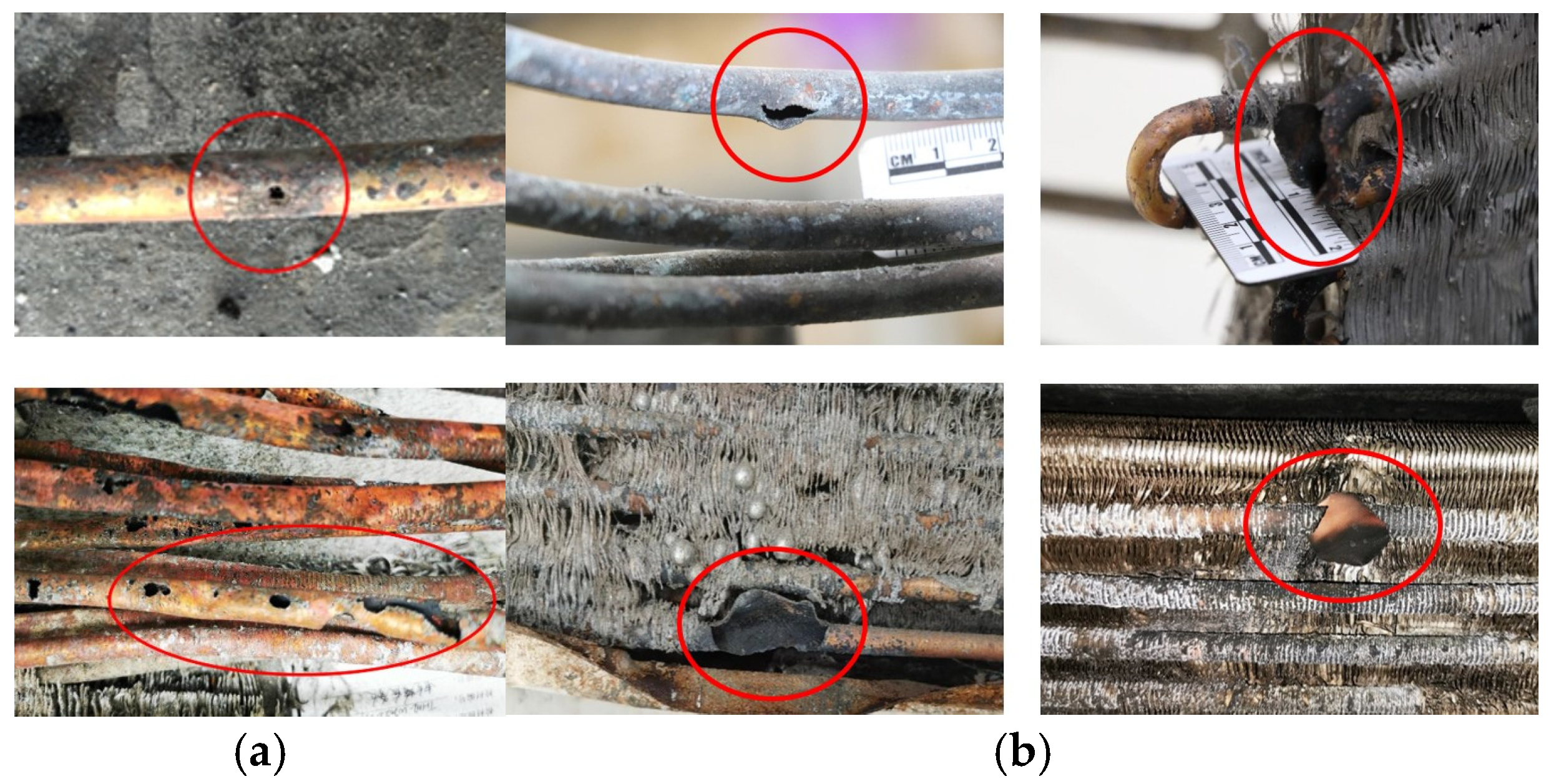
Our research team has examined multiple air conditioner fire incidents over the past five years. Initial inspections of the damaged remains of failed air conditioner condensers showed that copper tube ruptures primarily occur in two ways: those caused by fire erosion and those caused by localized thinning of the inner wall due to corrosion, which then tear under pressure. We performed statistical analysis on the frequency of these two types of ruptures and instances of copper tube tearing due to pressure release, as shown in Table 1. Fire-induced erosion ruptures are common and frequently found in air conditioner remnants. Tear-induced ruptures are less frequent, with typically one per air conditioner remnant, usually marking the first point of pressure release. In air conditioner B, we observed a rupture caused by tearing. Both air conditioners A and B show both types of ruptures, making them ideal for studying the effects of flame erosion and corrosion on copper tube tearing. Figure 1 displays visual fragments of the two types of copper tube fractures.

Table 1.
Number of ruptures and discoloration conditions in different air conditioner fires.
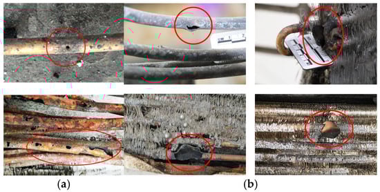
Figure 1.
Two types of copper pipe rupture openings. (a) Fire-caused; (b) Pressure-release-induced. Red circles are used to mark the rupture of the copper tube.
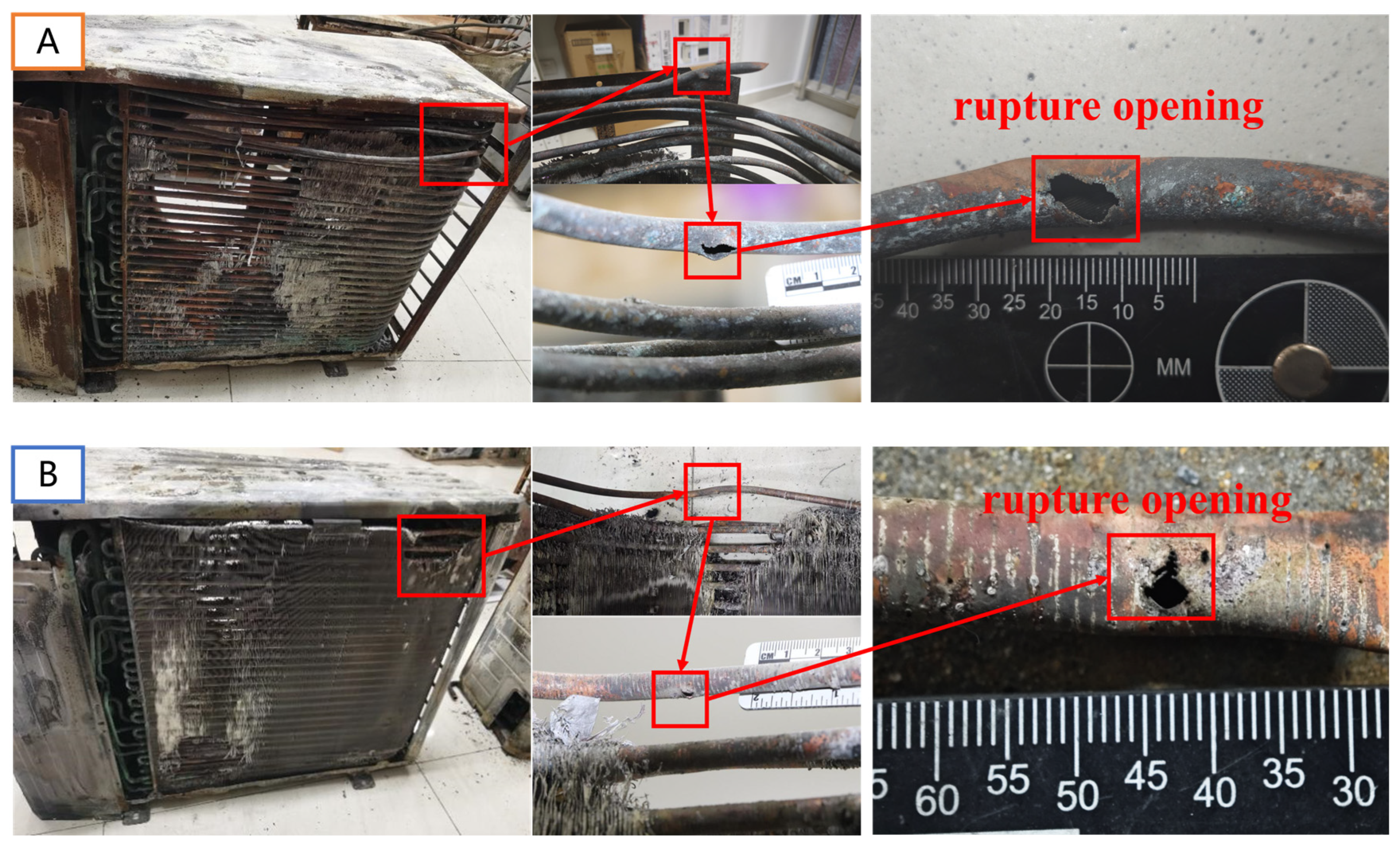
Figure 2 shows the appearance of a representative post-fire air conditioner. Panels consisting of an internally threaded copper tube and aluminum fins are typical components of Heating Ventilation and Air Conditioning (HVAC) systems. Copper tubes are extracted from the air conditioner condensers. The tubes are made of phosphorus deoxidized copper. The average outside diameter of the tubes is 8.5 mm, which is the size of the optimized design for this type of air conditioner. The condensers, compressors, and connecting pipelines of both outdoor units are examined. Figure 2 illustrates the rupture locations for Air Conditioner A and Air Conditioner B. Air Conditioner A shows a more severe degree of fire damage and Air Conditioner B exhibits only partial fire damage. The rupture in Air Conditioner A was located at a condenser elbow, while the rupture in Air Conditioner B was found in the straight tube at the upper left corner of the condenser. Notably, A and B are two air conditioners damaged in the same air conditioner fire incident.
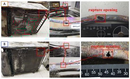
Figure 2.
(A,B) Locations of the copper tube ruptures in condensers.
2.2. Copper Tube Sampling Location
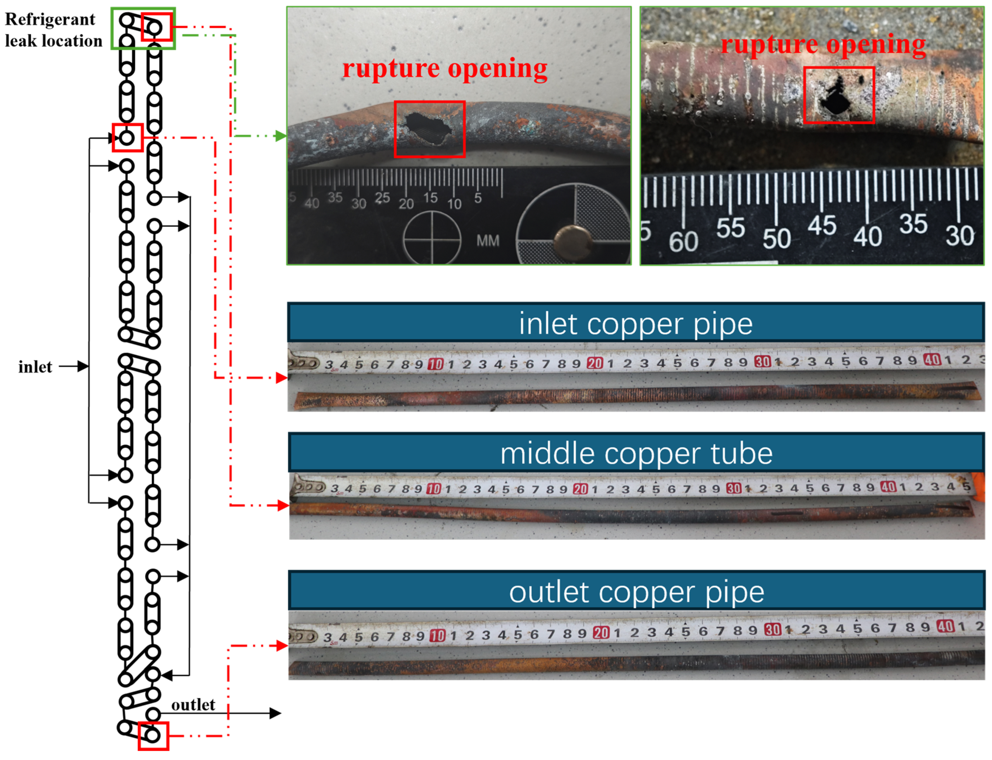
Figure 3 shows the sample sites for the copper tubes. The rupture openings of the copper tubes from both air conditioners are inspected. Refrigerant flow inlet, middle, and outlet copper pipes are examined for the two air conditioners.
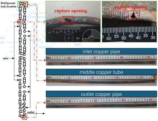
Figure 3.
Refrigerant flow path within the condenser and the copper tube samples from different locations. The green box is used to mark the refrigerant leak location.
2.3. Experimental Step
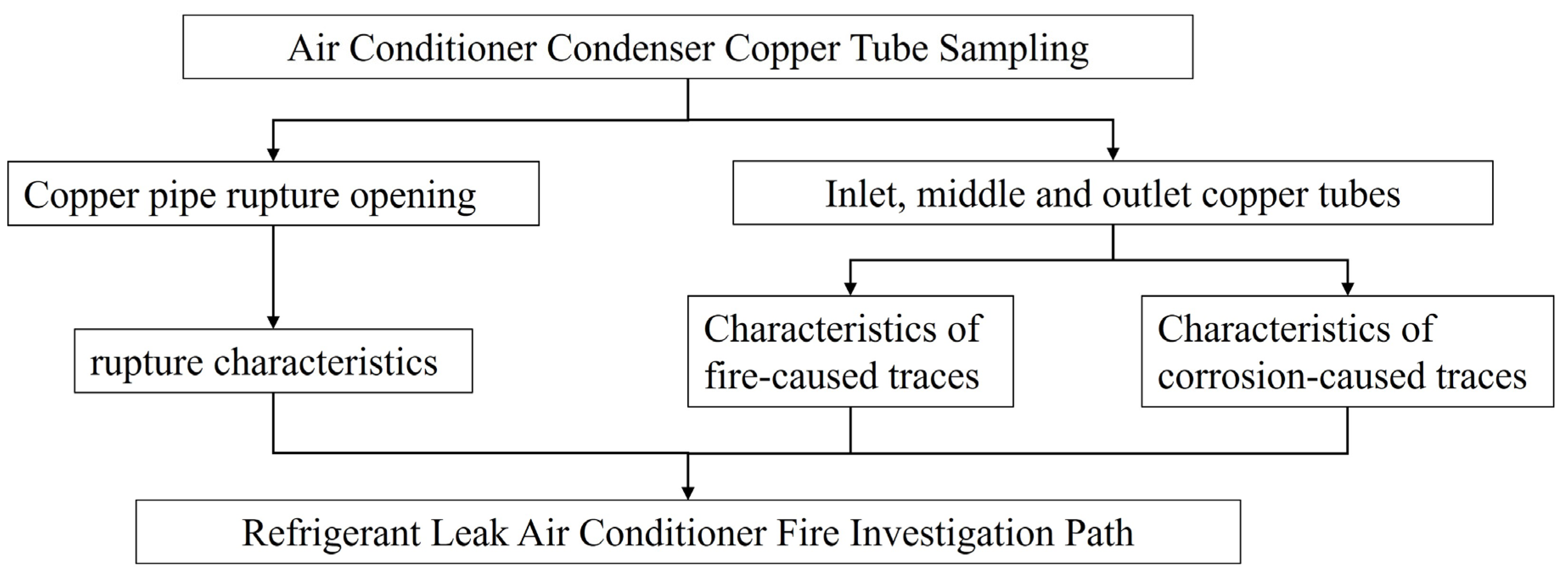
Figure 4 illustrates the research process for this research. The surface macro-morphology of the copper tube was analyzed using an optical microscope (OLYMPUS, Tokyo, Japan). Surface micro-morphology and elemental composition were examined using SEM-EDS (HITACHI, Ibaraki Prefecture, Japan). Cross-sectional samples of the copper tube were prepared through a series of steps, including cleaning, fixing, embedding, grinding, and polishing. These sections are observed and analyzed using a metallurgical microscope (OLYMPUS, Tokyo, Japan) with a measurement accuracy of 0.01 . The grinding process is conducted layer by layer. The observation procedure is repeated to capture additional cross-sectional images when each layer is removed.
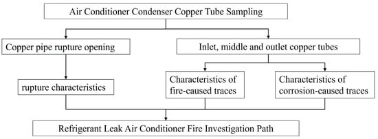
Figure 4.
Research flowchart.
3. Results and Discussion
3.1. Rupture Openings Characteristics
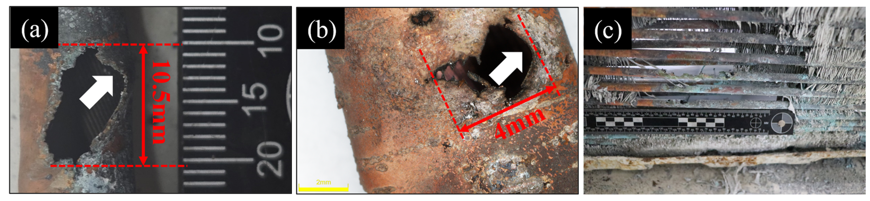
Figure 5 presents samples from the ruptured openings of the copper tubes in air conditioners A and B. The arrow positions in Figure 5a,b indicate that the ruptured openings of the copper tubes exhibit localized deformation, with the ruptured edges extending outward. The condenser operates under significant pressure within the air conditioning circulation system. When the local compressive strength of the copper tube is inadequate to withstand the system’s pressure, it will fail, resulting in the escape of the liquid refrigerant through the resulting crack. Consequently, the ruptured edges typically extend outward. In instances where the copper tube material is not subjected to high pressure along the pipeline, pressure marks will be absent on the resulting rupture of the copper tube, as illustrated in Figure 5c. This type of hole is primarily linked to the elevated temperature of the flame, and the quantity is not singular.
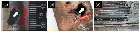
Figure 5.
(a) Copper pipe rupture opening in air conditioner A, (b) copper pipe rupture opening in air conditioner B, and (c) fire holes in the bottom of the condenser of Air Conditioner A. The arrow points to the position of deformation at the edge of the pressure tear rupture.
Figure 5a illustrates an axial rupture of the copper tube, measuring a maximum length of 10.5 mm and covering an area of approximately 40 mm2. The axial rupture may be associated with the manufacturing process of the internally threaded copper tube. In the rotary drawing process, the material experiences significant tensile stress in the drawing direction, leading to a stress concentration zone along the tube’s axial direction. The stress concentration zone reduces the material’s strength. Consequently, it exhibits sensitivity in a corrosive environment, and the rupture tends to propagate along the axial direction. The elbow region of the copper tube is recognized as a stress concentration zone and is among the most vulnerable areas to rupture [21]. Figure 5b illustrates a crack that forms in the circumferential direction, exhibiting a maximum length of approximately 4 mm and an area of roughly 5 mm2. The crack edge depicted in Figure 5b exhibits an irregular morphology influenced by flame, characterized by sharp protrusions resulting from the high-temperature melting of the copper tube.
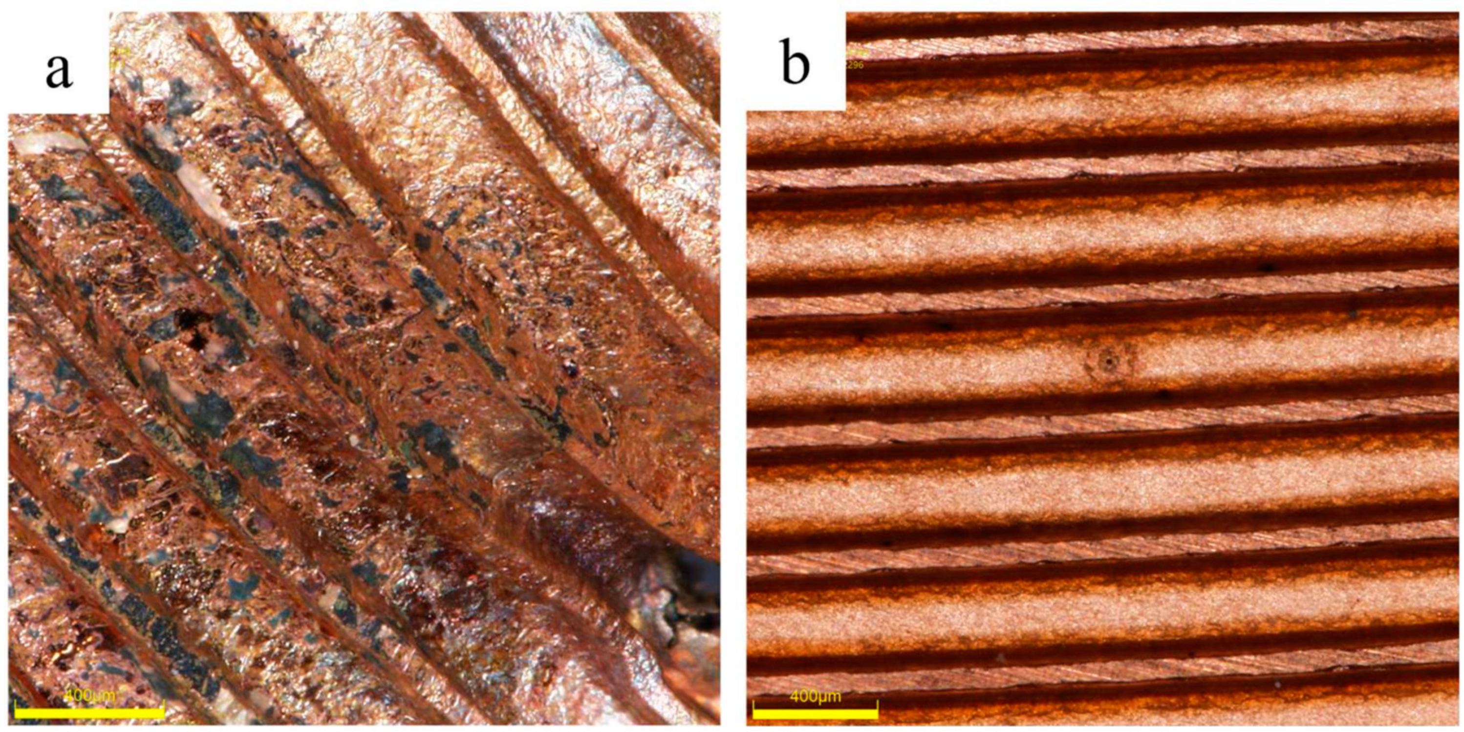
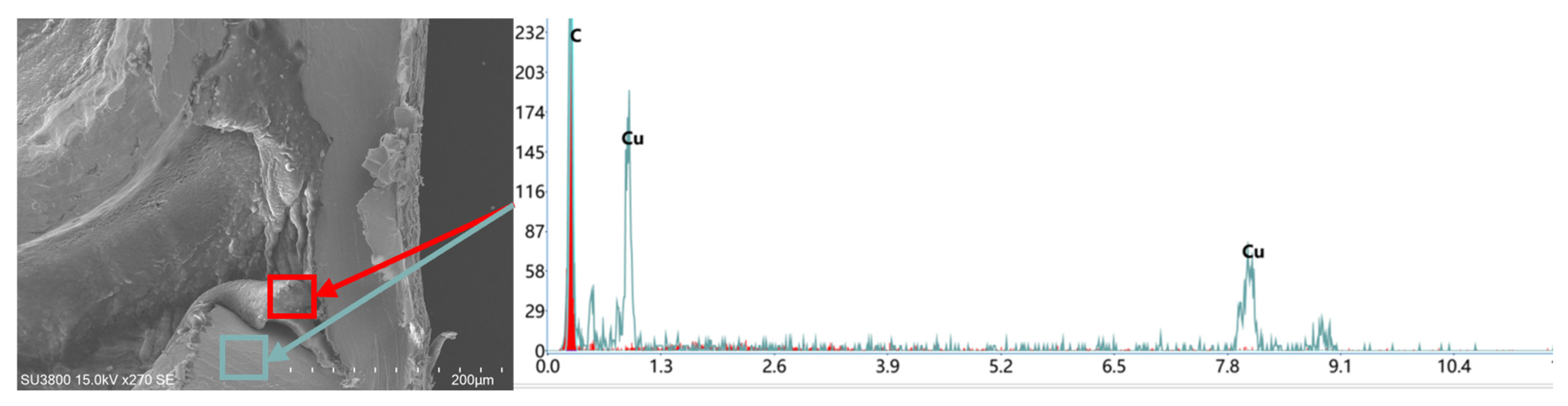
To elucidate that the failure of air conditioner A resulted from corrosion and the failure of air conditioner B was associated with fire, and to furnish additional rationale for the inclusion of air conditioners A and B in Table 1, the pipes adjacent to the ruptured copper tubes of both air conditioners were collected and examined under a stereo microscope as depicted in Figure 6 (Figure 6a represents air conditioner A and Figure 6b represents air conditioner B). Ant nest corrosion may also manifest in regions far from the site of failure [10]. In contrast to the inner surface of air conditioner A, the inner surface of air conditioner B is comparatively clean, exhibiting no discernible discoloration indicative of corrosion on the copper tube. The surface exhibits no flaky or spotted degradation, but the inner surface of Figure 6a displays discoloration due to corrosion. It is tentatively concluded that the failure of air conditioner A may be associated with corrosion. Refer to Section 3.3 for a comprehensive study of the failure of air conditioner A. The failure of air conditioner B may be associated with the fire. In Figure 6b, the darker curved dividing line was seen to be positioned on both sides of the groove at the base of the internal threaded copper tube. The copper tube was severed at this location for SEM-EDS analysis, revealing that its primary constituent was carbon, attributable to leftover carbon from the high temperature of the lubricating fluid, unrelated to corrosion, as shown in Figure 7.

Figure 6.
A macroscopic picture of the copper tube’s surface in the vicinity of the failure location. (a) air conditioning unit A; (b) air conditioning unit B.
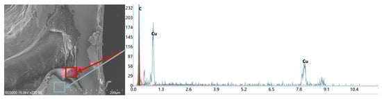
Figure 7.
SEM-EDS investigation of the materials on each side of the groove of air conditioner B.
3.2. Effect of Flame on Morphology
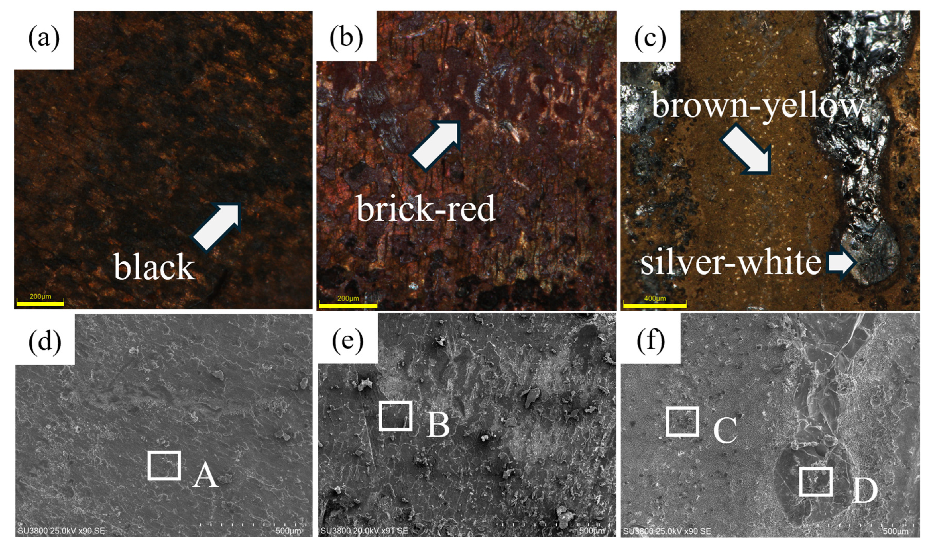
The influence of elevated temperature flames on the morphology of copper tubes results in two primary outcomes: chemical interactions between the copper tube and adjacent gases, and the melting of metals. The aforementioned processes will result in a decrease in the wall thickness of the copper pipe. Consequently, the wall is unable to endure internal pressure and will ultimately fail. The original color of the air conditioning copper tubing is orange-red. Figure 8 classifies the surface morphology of the copper tube according to observed color changes. Four distinct colors are black, brick red, brownish yellow, and silver-white. The component analysis is conducted on the four areas illustrated in Figure 8.
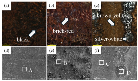
Figure 8.
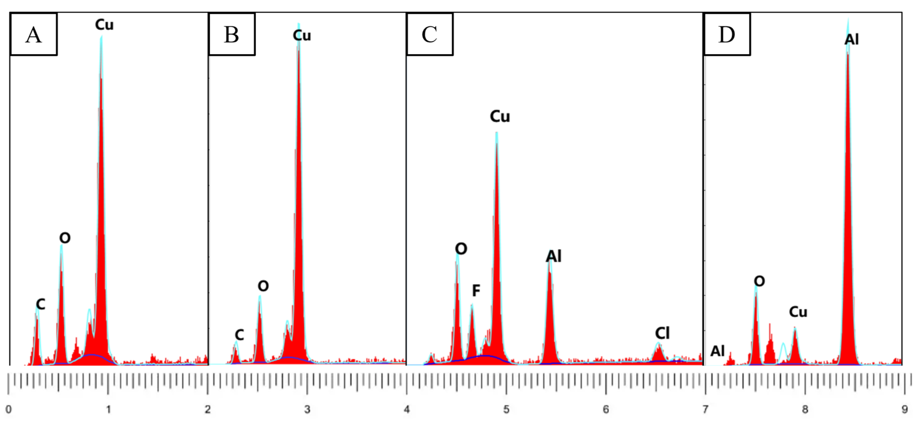
The color changes observed on the copper tube surface under high-temperature flame exposure. Images (a–c) are OM (optical microscopy) images, while (d–f) are the corresponding SEM (scanning electron microscopy) images. Regions A, B, C, and D indicate the areas selected for EDS (energy dispersive spectroscopy) analysis corresponding to the observed colors.
Black and brick-red discolorations manifest as spots on the tube’s surface (Figure 8a,b). The regions primarily consist of copper oxide (CuO) and cuprous oxide (Cu2O), resulting from the reaction between copper and oxygen. The carbon observed in these areas may stem from the combustion of organic materials or environmental carbon particles (Figure 9A,B). It is worth noting that copper oxide and cuprous oxide frequently coexist [6,22].

Figure 9.
EDS results for regions (A–D) corresponding to those in Figure 8.
The occurrence of brownish-yellow discoloration on the surface of the copper tubing is atypical. EDS analysis indicates the presence of fluorine, chlorine, and aluminum in this region, alongside copper and oxygen (Figure 9C). Fluorine and chlorine are typically sourced from air conditioning refrigerants and lubricating oils. At elevated temperatures, copper interacts with these elements, resulting in the formation of brownish-yellow deposits on the surfaces of pipes. Furthermore, silvery-white attachments, primarily composed of aluminum (Figure 9D), were noted surrounding the brownish-yellow regions depicted in Figure 8f. The aluminum identified in the brownish-yellow region results from aluminum–copper diffusion in that area.
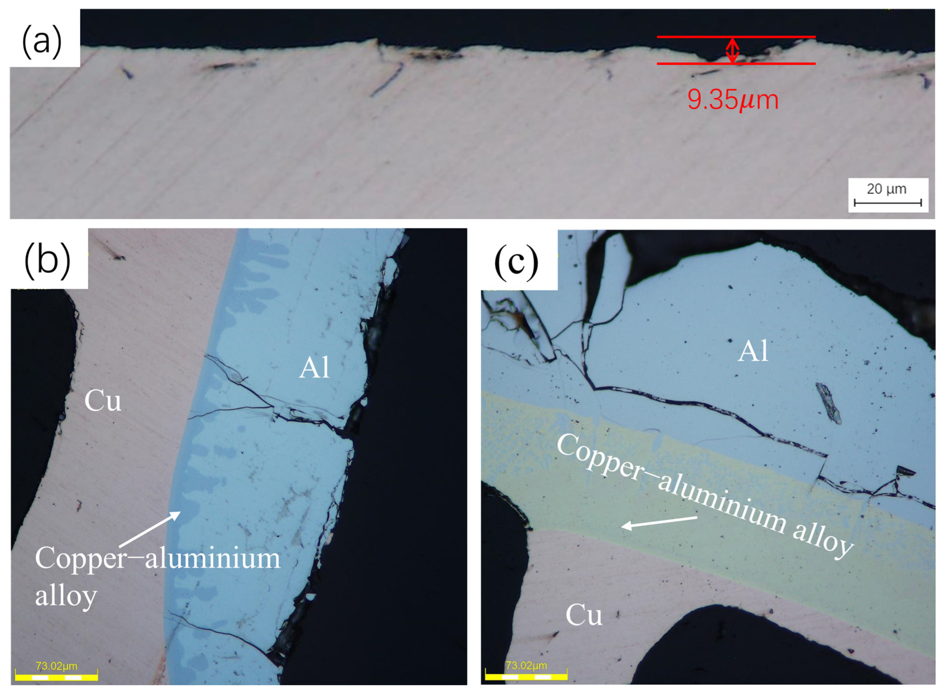
Figure 8a is taken from the black spot region on the outer surface of the copper tube. Interestingly, it is observed that the reaction of copper tubes with common gases, such as oxygen, at elevated temperatures leads to a reduction in the thickness of the copper tubes. The loss thickness caused by oxidization is around 9.35 μm. It indicates that high-temperature oxidation is not the main reason for the generation of the rupture. Copper tubes at elevated temperature conditions are more susceptible to rupture owing to the production of copper–aluminum alloys.
Notably, all primary rupture sites displayed the presence of molten aluminum. Copper and aluminum atoms, derived from the aluminum alloy fins that are closely bonded to the internally threaded copper tubes, undergo diffusion and interfacial reactions at elevated temperatures. This interaction results in rupture caused by microstructural inhomogeneities, porosity, and thermal expansion stresses [23,24]. A study indicated that copper and aluminum initiate mutual corrosion via diffusion at temperatures starting from 100 °C, with the process becoming more pronounced at elevated temperatures. A black band layer, consisting of a copper–aluminum alloy, forms at approximately 500 °C. These temperatures can be easily attained in air conditioning fires.
Figure 10b,c illustrates cross-sections of a copper tube with aluminum bonded to its outer surface, displaying three distinct color layers. The outermost layer consists of aluminum, which appears blue under a metallurgical microscope. The innermost layer is copper, exhibiting a light-yellow color under the same conditions, while the middle layer is composed of a copper–aluminum alloy. The coloration of the copper–aluminum alloy typically corresponds to the element present in greater concentration.
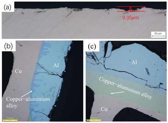
Figure 10.
Cross-sectional characteristics of the copper tube. (a) extracted from the black spot area on the external surface of the copper tube. Conversely, (b,c) are extracted from aluminum-coated regions at various locations on the external surface of the copper tube.
3.3. Effects of Corrosion on Morphology
The study of corrosion effects on the morphology of copper tubes focused mainly on the inner surface. The inner surface experiences less oxygen exposure and is less influenced by elevated temperatures compared to the outer surface [25]. Corrosion products observed on copper can be classified into two categories. Ant nest corrosion represents the first category. In carboxylic acid environments, copper undergoes a reaction resulting in the formation of copper oxide and cuprous oxide. The corrosion products are similar to those generated under high-temperature flame exposure; however, the mechanisms of formation are distinct. Ant nest corrosion occurs due to the accumulation of corrosion products, leading to the expansion of cracks and the formation of a network of branching cracks [6,7,21]. Atmospheric corrosion represents the second type of corrosion. Copper interacts with water, oxygen, and carbon dioxide in humid air, resulting in the formation of copper alkali carbonate [12,13]. Nonetheless, this corrosion product typically fails to remain intact at elevated temperatures, decomposing at approximately 220 °C.
- (1)
- Ant Nest Corrosion Characteristics
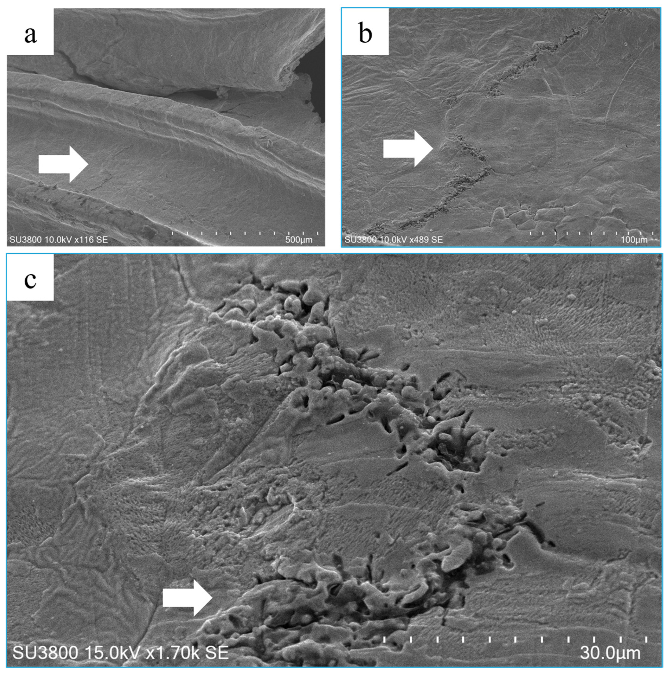
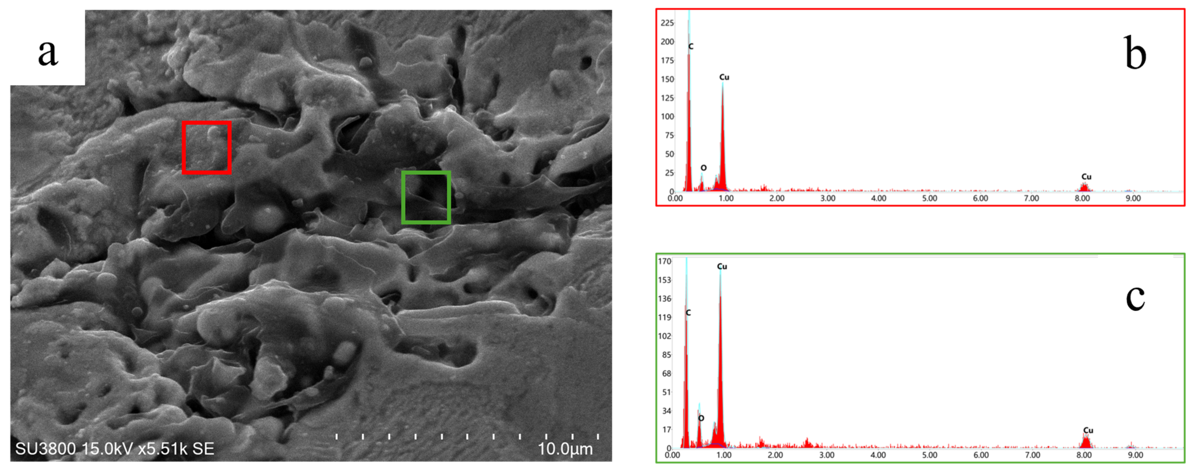
Figure 11a,b illustrate the positions of corrosion marks in air conditioner A. Various corrosion products are evident around the cracks, manifesting as patches of distinct colors (Figure 11c). SEM analysis of this region reveals the presence of many microcracks and localized deformation around the rupture site. We also identified minute microcracks in the groove of the interior threaded copper tube next to the rupture, as seen in Figure 12a. Upon expanding the region, it was determined that the fractures consisted of many corrosion pits of differing depths, as seen in Figure 12b,c, and the surface exhibited significant roughness. Figure 13a illustrates a distinct local melting event around the corrosion pit, revealing a reasonably smooth copper surface; yet, the corrosion pit has a notable depth. EDS study of this location indicated that the primary components are mostly C, O, and Cu. The elevated carbon content may be associated with the organic materials persisting after corrosion or high-temperature combustion at this location. The presence of O and Cu components suggests that the sediments inside the corrosion pit may mostly exist as CuO and Cu2O. Figure 11d illustrates the cross-sectional characteristics of the sample obtained at this site. Cross-sectional analysis indicates the presence of craters resembling those produced by ant nest corrosion, distributed across the cross-section. Shallow craters and fine cracks near the inner surface interconnect to create a network of branching fissures. The cracking paths traverse the entire cross-section of the copper tubes. In the context of corrosion products of copper tubing exposed to carboxylic acid, high-temperature exposure from a flame leads to the formation of more stable compounds, specifically CuO and Cu2O. Distinguishing the presence of carboxylic acid corrosion through surface morphology observation of copper tubes is challenging; however, preparing a cross-section allows for the examination of the corrosion path.
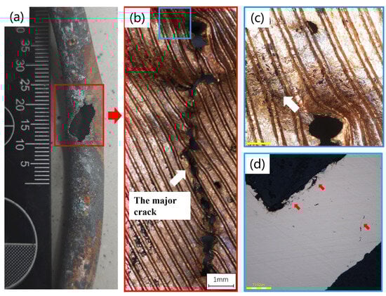
Figure 11.
Optical micrographs of corrosion traces at the location of the rupture. (a) The initial state of the rupture. (b) The arrow indicates a major crack. The rupture occurred in alignment with the rotational pulling direction of the copper tube, at an angle to the threaded strips. (c) The arrow indicates the discolored region next to the rupture. (d) The cross-section of the area prepared by the discolored area, with arrows pointing to the location of the various craters and cracks. (b) presents an enlarged image of the red box position in (a), while (c,d) depict surface and cross-sectional views of the region indicated in (b).
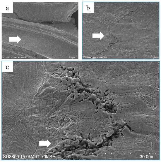
Figure 12.
SEM picture of the area shown in Figure 11c. (a–c) represent the same region at varying magnifications, showing a microcrack associated with corrosion. The arrows in a and b indicate the microcracks next to the rupture opening, whereas the arrow in c denotes the accumulation of copper melt at the crack’s edge. The majority of the white dots in the picture are copper oxides, which appear white under SEM owing to their poor conductivity.
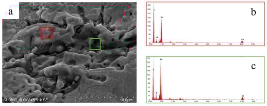
Figure 13.
EDS study of the indicated location in Figure 12c. (a) presents an enlarged depiction of the arrow’s location in Figure 12a, where the melting phenomenon on the corrosion pit’s surface is evident. (b) displays the EDS results from the pit’s surface, while (c) illustrates the EDS results from the pit’s deeper region. All analyses reveal the presence of only three elements: C, O, and Cu, with a higher concentration of C closer to the surface.
Our study revealed that the corrosion prior to the fire was characterized as ant nest corrosion, evident through the presence of cracks of specific depth on the copper tube’s surface. Following exposure to high temperatures from the flame, the corrosion products within these cracks predominantly consisted of copper oxides, and the surface of the pits exhibited melting marks. This indicates that the corrosion products were influenced by the elevated temperatures. Furthermore, the cross-section displayed an ant nest corrosion path, which could not have formed a corrosion path with melting marks on the surface post-fire.
- (2)
- Atmospheric Corrosion Characteristics
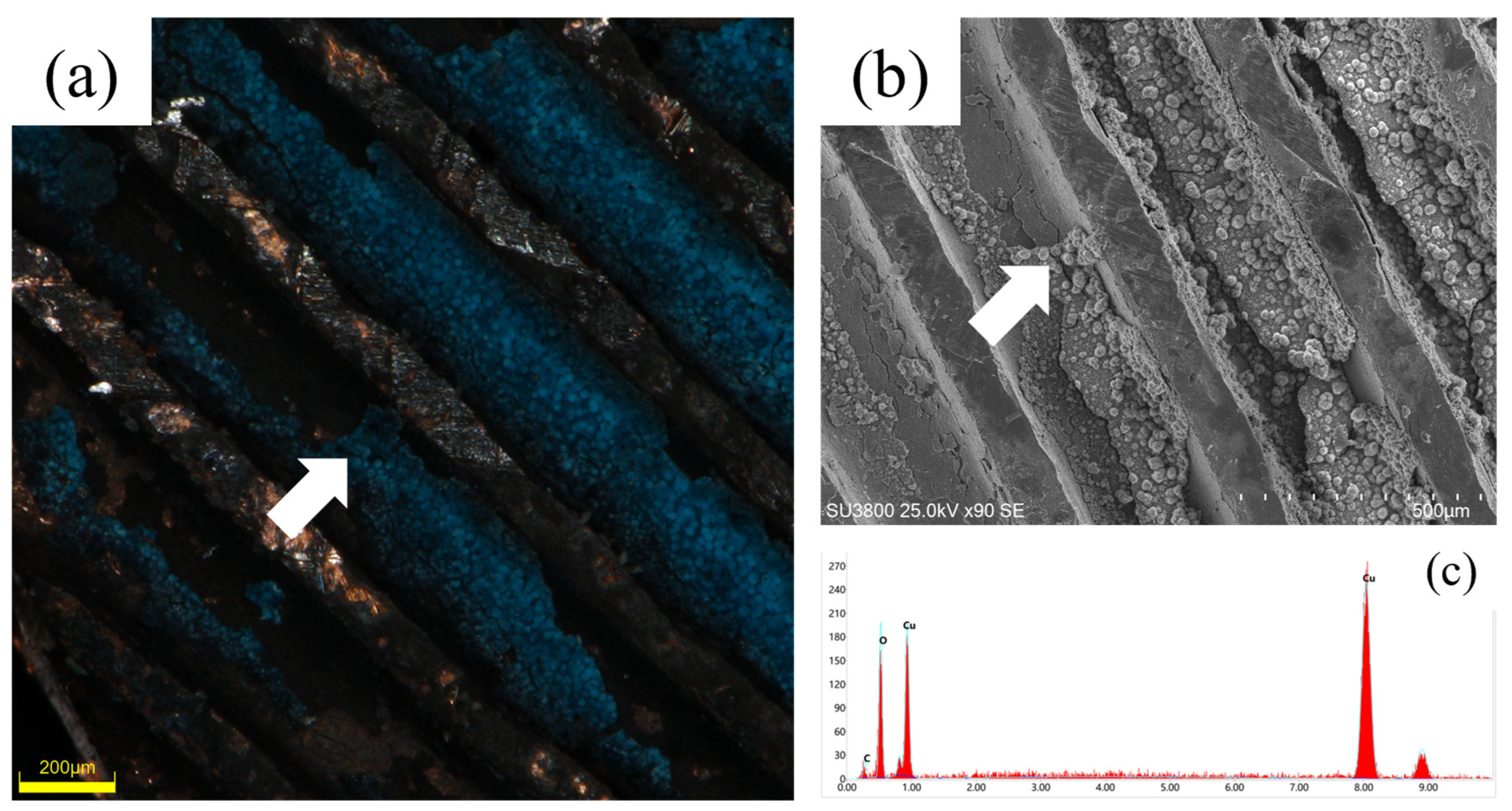
Figure 14 illustrates the morphological characteristics of copper tubes located at the condenser outlet of the air conditioning unit’s bottom. Figure 14a illustrates that the grooves on the inner surface are coated with a notable blue layer. Figure 14b illustrates regions characterized by granular or clustered deposits that are unevenly distributed, displaying typical corrosion morphology. The deposits primarily comprise carbon, oxygen, and copper (Figure 14c). This phenomenon has been consistently observed at the base of condensers during various fire incidents. The primary cause is likely associated with the humid environment resulting from residual moisture accumulation following fire rescue operations. This post-fire corrosion phenomenon indicates that the bottom of air conditioner condensers is especially susceptible to this form of corrosion.

Figure 14.
(a) Arrow pointing to the location of blue corrosion products. (b) SEM image of blue particles. (c) EDS spectrum of blue particles.
3.4. Investigative Pathway
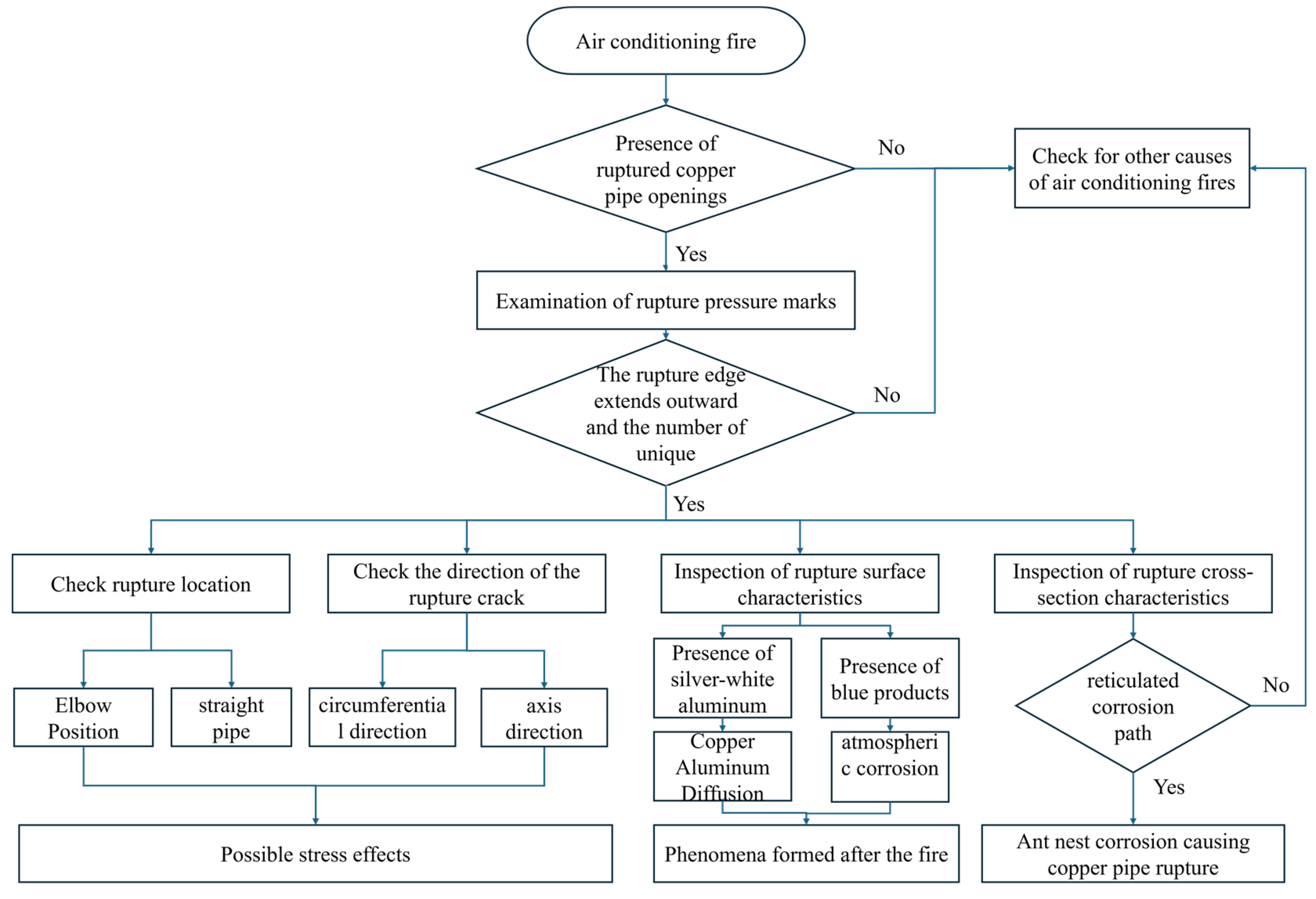
Figure 15 summarizes the investigation pathway concerning air conditioning fires associated with refrigerant leaks.
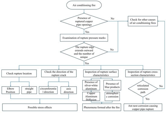
Figure 15.
Path of investigation for air conditioning fires involving refrigerant leaks.
- The initial step involves assessing the potential correlation between the fire and a refrigerant leak, specifically the occurrence of a rupture in a copper tube.
- The next step involves determining the cause of the copper tube rupture. High-pressure-release triggered ruptures are defined by the outward expansion of the rupture edge and a unique number of rupture openings.
- The rupture’s location and the tear’s direction must be analyzed to determine their consistency with stress concentration areas typically observed in air conditioning systems.
- Furthermore, the features surrounding the rupture should be analyzed for alterations resulting from the fire. Although the elevated temperature from the flame may obscure certain corrosion features, the corrosion pathways in the upper cross-section of the copper tube remain discernible. Cross-sectional observation enables the detection of these paths, facilitating a comprehensive analysis of the rupture and its causal factors.
4. Conclusions
The primary causes of air conditioner condenser copper tube rupture are fire erosion and localized thinning of the inner wall due to corrosion, which then fails under pressure. This study obtained representative macroscopic and microscopic characteristics of copper tubes in air conditioner fires through experiments, with the main findings summarized as follows:
- (1)
- The copper tubes display various surface colors due to reactions with oxygen, chlorine, and fluorine from the surrounding air, refrigerant, and lubricants. Ruptures caused by fire typically occur in areas with copper–aluminum alloys, showing color stratification in the cross-sectional metallographic structure.
- (2)
- Ant nest corrosion was the root cause of the rupture of the copper pipe that was hidden by the flames. Ant nest corrosion, characterized by craters and cracks, is often linked to such ruptures. Even after fire exposure, corrosion traces can be identified through cross-sectional analysis.
- (3)
- When the rupture is at the bottom of an air conditioner, atmospheric corrosion should be considered, as blue corrosion products are common.
- (4)
- An investigation into refrigerant leaks during air conditioning fires involves examining the expanding rupture opening, determining if it is in a stress concentration area, and analyzing the fire and corrosion features around the rupture.
Author Contributions
Conceptualization and writing—original draft preparation, Y.O. and C.L.; Methodology and writing—review and editing, M.F., J.Z., W.M., S.C. and S.Z. All authors have read and agreed to the published version of the manuscript.
Funding
This research was funded by National Key R&D Program of China (Grant No. 2022YFC3080900), National Natural Science Foundation of China (Grant No. 52074163), China National Fire and Rescue Administration Science and Technology Program Project (Grant No. 2023XFCX26), and China Postdoctoral Science Foundation (Grant No. 2024M751713). And the APC was funded by National Natural Science Foundation of China (Grant No. 52074163).
Institutional Review Board Statement
Not applicable.
Informed Consent Statement
Not applicable.
Data Availability Statement
The raw data supporting the conclusions of this article will be made available by the authors on request.
Conflicts of Interest
Author Shouhai Chen was employed by the company Hisense Air Conditioning Co., Ltd. Author Shoulei Zheng was employed by the Tsingdao Haier Home Life Service Co., Ltd. The remaining authors declare that the research was conducted in the absence of any commercial or financial relationships that could be construed as a potential conflict of interest.
References
- Li, Y.; Yang, J.; Wu, X.; Liu, Y.; Zhuang, Y.; Zhou, P.; Han, X.; Chen, G. Leakage, diffusion and distribution characteristics of refrigerant in a limited space: A comprehensive review. Therm. Sci. Eng. Prog. 2023, 40, 101731. [Google Scholar] [CrossRef]
- Tsuda, N.; Yoshizawa, M.; Iwai, H. Comparison of Flammability of Low-GWP Refrigerants Using 1.76-m3 Combustion Chamber. Combust. Sci. Technol. 2021, 193, 664–676. [Google Scholar] [CrossRef]
- Jia, L.; Jin, W.; Zhang, Y. Experimental study on R32 leakage and diffusion characteristic of wall-mounted air conditioners under different operating conditions. Appl. Energy 2017, 185, 2127–2133. [Google Scholar] [CrossRef]
- Yadav, S.; Liu, J.; Kim, S.C. A comprehensive study on 21st-century refrigerants-R290 and R1234yf: A review. Int. J. Heat Mass Transf. 2022, 182, 121947. [Google Scholar] [CrossRef]
- He, H.; Yang, Z.; Zhang, Y.; Chen, Y.; Hou, Z. Comprehensive risk assessment of flammable refrigerants in HVAC systems based on Bayesian networks and consequence modeling. Eng. Fail. Anal. 2024, 163, 108579. [Google Scholar]
- Manik, T.; Sakai, M.; Situmorang, R.S.; Kawai, H.; Sasaki, D.; Oishi, Y.; Ambarita, H. Effect of phosphorus on the ant-nest corrosion mechanism. Mater. Today Commun. 2023, 36, 106560. [Google Scholar] [CrossRef]
- Liu, X.; Li, H.; Zhao, X.; Chen, Y.; Wang, S. Comparison of the corrosion behavior of copper tubes in formic acid and acetic acid environment. Mater. Corros.-Werkst. Und Korros. 2021, 72, 1919–1927. [Google Scholar] [CrossRef]
- Wang, Z.; Li, H.; Cheng, D.; Qin, S.; Li, D.; Zhang, X. A laboratory study of the failure analysis of copper tube used in the air conditioning heat exchanger. Mater. Corros.-Werkst. Und Korros. 2024, 75, 924–931. [Google Scholar] [CrossRef]
- Bastidas, D.M.; Criado, M.; Fajardo, S.; La Iglesia, V.M.; Cano, E.; Bastidas, J.M. Copper deterioration: Causes, diagnosis and risk minimization. Int. Mater. Rev. 2010, 55, 99–127. [Google Scholar] [CrossRef]
- Chandra, K.; Kain, V.; Shetty, P.; Kishan, R. Failure analysis of copper tube used in a refrigerating plant. Eng. Fail. Anal. 2014, 37, 1–11. [Google Scholar] [CrossRef]
- Cozzarini, L.; Marsich, L.; Schmid, C. Ant-nest corrosion failure of heat exchangers copper pipes. Eng. Fail. Anal. 2020, 109, 104387. [Google Scholar] [CrossRef]
- Chae, H.; Wang, H.; Hong, M.; Kim, W.C.; Kim, J.-G.; Kim, H.; Lee, S.Y. Stress Corrosion Cracking of a Copper Pipe in a Heating Water Supply System. Met. Mater. Int. 2020, 26, 989–997. [Google Scholar] [CrossRef]
- Suh, S.H.; Suh, Y.; Yoon, H.G.; Oh, J.H.; Kim, Y.; Jung, K.; Kwon, H. Analysis of pitting corrosion failure of copper tubes in an apartment fire sprinkler system. Eng. Fail. Anal. 2016, 64, 111–125. [Google Scholar] [CrossRef]
- Li, J.; Yang, Z.; He, H.; Zhang, C.; Hao, S. Research on the flammability and explosion characteristics of typical low GWP refrigerants. J. Loss Prev. Process Ind. 2022, 80, 104923. [Google Scholar] [CrossRef]
- Askar, E.; Schröder, V.; Schmid, T.; Schwarze, M. Explosion characteristics of mildly flammable refrigerants ignited with high-energy ignition sources in closed systems. Int. J. Refrig.-Rev. Int. Du Froid 2018, 90, 249–256. [Google Scholar] [CrossRef]
- Hu, Y.; Yang, Z.; Hou, Z.; Zhao, Y. Study on the impacts of refrigerant leakage on the performance and environmental benefits of heat pumps using R513A as replacement of R134a. Int. J. Refrig. 2024, 168, 399–410. [Google Scholar] [CrossRef]
- Li, Y.; Yang, J.; Wu, X.; Liu, Y.; Zhou, P.; Yan, Y.; Han, X. Research on the field strength characteristics and the flammable area of refrigerants leakage into a confined space. Int. J. Refrig. 2023, 153, 308–322. [Google Scholar] [CrossRef]
- Zhang, W.; Yang, Z.; Li, J.; Ren, C.-X.; Lv, D.; Wang, J.; Zhang, X.; Wu, W. Research on the flammability hazards of an air conditioner using refrigerant R-290. Int. J. Refrig.-Rev. Int. Du Froid 2013, 36, 1483–1494. [Google Scholar] [CrossRef]
- Choi, S.-B.; Choi, D.-M. Study on Fire Risk of Air Conditioner through Fire Cases. Fire Sci. Eng. 2017, 31, 70–77. [Google Scholar] [CrossRef]
- Beasley, M.; Holborn, P.; Ingram, J.; Maidment, G. Causes, consequences and prevention of refrigeration fires in residential dwellings. Fire Saf. J. 2018, 102, 66–76. [Google Scholar] [CrossRef]
- Zhou, J.; Yan, L.; Tang, J.; Sun, Z.; Ma, L. Interactive effect of ant nest corrosion and stress corrosion on the failure of copper tubes. Eng. Fail. Anal. 2018, 83, 9–16. [Google Scholar] [CrossRef]
- Zhang, J.; Chen, T.; Su, G.; Li, C.; Zhao, F.; Mi, W. Microstructure and component analysis of glowing contacts in electrical fire investigation. Eng. Fail. Anal. 2022, 140, 106539. [Google Scholar] [CrossRef]
- Chen, Y.; Xie, J.; Wang, A.; Mao, Z.; Gao, P.; Chang, Q. In-Situ Observation and Analysis of the Evolution of Copper Aluminum Composite Interface. Metals 2023, 13, 1558. [Google Scholar] [CrossRef]
- Fan, S.; Guo, X.; Li, Z.; Ma, J.; Li, F.; Jiang, Q. A Review of High-Strength Aluminum-Copper Alloys Fabricated by Wire Arc Additive Manufacturing: Microstructure, Properties, Defects, and Post-processing. J. Mater. Eng. Perform. 2023, 32, 8517–8540. [Google Scholar] [CrossRef]
- Alawadhi, M.; Phelan, P.E. Review of Residential Air Conditioning Systems Operating under High Ambient Temperatures. Energies 2022, 15, 2880. [Google Scholar] [CrossRef]

Disclaimer/Publisher’s Note: The statements, opinions and data contained in all publications are solely those of the individual author(s) and contributor(s) and not of MDPI and/or the editor(s). MDPI and/or the editor(s) disclaim responsibility for any injury to people or property resulting from any ideas, methods, instructions or products referred to in the content. |
© 2025 by the authors. Licensee MDPI, Basel, Switzerland. This article is an open access article distributed under the terms and conditions of the Creative Commons Attribution (CC BY) license (https://creativecommons.org/licenses/by/4.0/).