Abstract
Recent catastrophic bridge fire incidents have highlighted the critical need for effective post-fire assessment of bridges, thereby challenging the dominant practice of complete replacement following these destructive events. This study investigates the post-fire performance of bare, isolated, and Carbon Fiber Reinforced Polymer (CFRP)-repaired Reinforced Concrete (RC) bridge columns under single-unit truck impact followed by air blast. This extreme loading scenario was deliberately selected given the increased vulnerability of bridge columns to this loading scenario in the recent few years. Three-dimensional Finite Element (FE) models of the structural system and surrounding environment were developed and validated in LS-DYNA. The effectiveness of two in-situ retrofitting schemes in mitigating damage and enhancing structural integrity of three column diameters under the selected multi-hazards was assessed. Results demonstrated that wrapping the bottom half of the column height prevents shear failure and significantly reduces the damage under the coupled impact and blast. In contrast, employing a combination of CFRP bars and externally bonded sheets showed limited enhancement on post-fire impact and blast performance. This study provides critical insights into the feasibility and efficacy of retrofitting bridge columns that have experienced fire, thus laying the groundwork for the reconsideration of current design and rehabilitation protocols.
1. Introduction
It is widely recognized that, due to their location near the traffic, bridge columns are highly susceptible to extreme events, including fires, vehicle collisions, and air blasts, especially for columns without adequate protection systems. Although bridge site fire incidents are less frequent than many other extreme demands, their consequences can be profound, resulting in significant structural damage and deterioration, substantial financial burdens, and, above all, tragic loss of lives and property. According to a dataset compiled by the New York Department of Transportation (NYDOT), which comprehensively recorded bridge collapse incidents between 1960 and 2013, fire-related bridge collapses surpassed those caused by other typical causes, including construction and design flaws, seismic events, and geotechnical problems [1]. While substantial research efforts have been dedicated to examining the performance of bridges under these traditional demands and deficiencies, fire effects have received limited attention.
Multiple research studies have indicated that the frequency of bridge fires across the U.S. has rapidly increased over the past few years, largely driven by the accelerated development of urban transportation systems and the corresponding increased volume of transported highly combustible goods and materials [2,3]. Yet, widely used bridge design standards provided by the American Association of State Highway and Transportation Officials (AASHTO) Load and Resistance Factor Design (LRFD) include limited guidance on structural analysis, design, and performance assessment following a fire event [4]. The National Fire Protection Association (NFPA 502) broadly discusses fire protection measures for elevated highways and bridges [5]. However, it only includes qualitative guidance on fire incident detection, traffic control, control of ignitable substances, and utilizing firefighter systems. Giuliani et al. noted that the absence of structural-fire design standards and specifications in relevant bridge codes stems from the complexities and uncertainties involved in reliably characterizing and modeling fire [6]. Consequently, a clear knowledge gap exists in understanding the structural behavior of bridges and their components during and after fire incidents.
As reported in multiple studies, bridge fires are mainly attributed to petrochemical leaks, overturned vehicles, tanker trucks carrying flammable goods, electrical issues, stored combustible materials, as well as other natural or intentional fires [1,6,7]. Regardless of the cause, uncertainties persist regarding critical factors that define fire intensity, including the temperature-time variation, the rate of heat release, flame origin, location, geometry, and the surrounding environmental conditions [8]. As a result, the extent of fire-induced damage may range from clearly apparent to being invisible to the naked eye. While concrete spalling is a visible sign of fire damage, distributions of stresses, micro-cracks, and concrete and steel strength degradation may not be observable [9]. Bridge support element post-fire performance should be reassessed if the element survived a fire to determine if sufficient structural integrity was maintained to keep the element in service, with or without repair.
Several research studies have demonstrated that the post-fire behavior of RC structural elements, including bridges, requires further attention and must be evaluated under dynamic or other high loading rate events [10,11,12]. Particularly, studies have indicated that the apparent increase in concrete’s strength gained under high loading rates significantly decreases after exposure to elevated temperature, necessitating a reasonable reassessment of the post-fire response of RC structural elements under dynamic loads [10,11,13]. Several research studies have examined the performance of fire-damaged RC structural elements subjected to high loading rates resulting from individual impact and blast loads [14,15,16,17]. These studies did not, however, investigate RC bridge pier column performance under the combined effects of vehicle impact and air blast after fire damage. Despite being infrequent, combined vehicle collisions and explosions have happened and resulted in catastrophic structural damage and collapse [18]. One similar multi-hazard event occurred recently in Philadelphia, Pennsylvania, when a tanker truck crashed and led to a series of explosions in the underground pipeline system [19]. This extreme event caused a significant portion of an overpass bridge to collapse.
Given their high strength-to-weight ratio, fiber-reinforced polymers (FRPs) have been proven to be an effective solution for retrofitting fire-damaged reinforced concrete (RC) columns, leading to improved structural performance [20]. In real-world applications, various techniques are used to incorporate FRP materials in retrofitting efforts. One such method, known as near-surface mounting (NSM), involves bonding thin, rigid FRP elements such as strips, bars, or ropes into grooves cut along the concrete surface. Another technique, referred to as externally bonded (EB) or hand layup, consists of adhering pre-manufactured FRP sheets or fabrics, typically 150 to 1500 mm wide, directly onto the surface of the element. More recently, hybrid retrofitting systems that combine different FRP components, including bars, strips, sheets, and plates, have been introduced. A common hybrid approach involves combining NSM bars or ropes with EB fabrics. The choice of the retrofitting scheme is primarily influenced by the structural component type and the level of strengthening required. For instance, NSM or EB FRP is commonly applied to the tension faces of beams and slabs to enhance flexural capacity, while column retrofitting often involves wrapping FRP fabrics around the full perimeter to increase axial load capacity and improve shear resistance through confinement [21].
While prior studies have examined fire-damaged RC elements under either impact or blast, no comprehensive assessment has been conducted on CFRP-retrofitted bridge columns subjected to the sequential combination of post-fire vehicle collision and air blast. Consequently, a clear knowledge gap exists in understanding the structural behavior of bridges and their components during and after fire incidents, and this study directly addresses that gap using validated high-fidelity numerical simulations. Hence, the novelty of this study lies in its focus on post-fire structural performance under combined vehicle impact and blast following fire, a multi-hazard scenario not previously explored in the literature. The study also presents a comparative evaluation of in-situ CFRP retrofitting schemes across different column diameters, offering insights into their effectiveness and scalability.
Building upon the findings in the previously cited studies, the current work evaluated the performance of in-situ retrofitting strategies using previously developed and validated three-dimensional finite element (FE) models of both undamaged and fire-damaged isolated bridge columns in LS-DYNA to better understand their behavior under combined impact and blast conditions [18,22]. Two retrofitting techniques were assessed for their ability to restore structural integrity to fire-damaged columns before being subjected to vehicular collision and air blast events. The first approach involved wrapping the columns with externally bonded carbon fiber reinforced polymer (CFRP) sheets. This method included three different configurations: full-height wrapping, partial-height wrapping, and intermittent wrapping along the column height. The second approach adopted a hybrid method previously introduced in the literature, combining externally bonded CFRP sheets with near-surface mounted (NSM) longitudinal FRP bars [23,24]. CFRP was selected not only based on earlier research but also due to its superior mechanical properties compared to glass fiber reinforced polymers (GFRPs), particularly in terms of strength, which is essential for resisting severe loading from impact and blast events [25]. The structural response of the retrofitted columns was compared with both fire-damaged columns without repair and undamaged columns across three different column diameters. Before conducting the performance comparisons, the modeling techniques were carefully reviewed and adjusted through validation against available experimental data on impact and blast scenarios.
2. Materials and Methods
2.1. Finite Element Model Overview
Three-dimensional nonlinear finite element models were developed in LS-DYNA to simulate bare, fire-damaged round reinforced concrete (RC) bridge columns, as well as those retrofitted with carbon fiber reinforced polymer (CFRP). The models included the columns, their supporting foundations, and the surrounding air and soil domains. This section outlines the numerical modeling methodology adopted to construct and analyze the overall structural system.
2.1.1. Load Application
To produce fire damage, the entire column periphery was initially exposed to a 90-min fire using the ISO-834 standard fire curve to define temperature variation over time [26]. Given that this current study aimed to examine the impact and blast response of bridge columns that survived a fire and retained sufficient integrity, the ISO-834 fire curve was assumed to reasonably characterize a relatively slow rate of temperature rise compared to hydrocarbon fire curves [27]. Fire duration and exposure conditions were selected during an earlier research phase based on reported fire incidents and publicly available databases [7,22,28,29,30]. The selection of a 90-min ISO-834 fire exposure as a representative scenario for assessing bridge performance under fire conditions is widely accepted in the realm of fire engineering assessment [28,29]. Following recommendations from the literature, thermal loads were applied as boundary conditions and modeled through a combination of radiation and convection heat transfer mechanisms [31]. Initial temperatures and fire-induced thermal loads were defined using LS-DYNA’s Initial Temperature Set and Boundary Temperature Set options, which apply temperature changes at the nodal level [32].
Since nominal compressive strength and stiffness are not recoverable after high-temperature exposure, concrete strength was assumed to depend on the maximum recorded temperature during the fire [33]. Due to the presence of through-section temperature gradients, an indirect approach was developed to estimate residual compressive strength before conducting impact and blast simulations. An initial three-dimensional transient heat transfer analysis was performed on representative bridge columns to capture realistic temperature fields across the column cross-section and key structural response characteristics. The column was then subdivided into horizontal and radial layers in alignment with the finite element mesh, and average temperatures were extracted for each layer at the end of the fire exposure. Each layer was assigned temperature-specific material properties, with compressive strength reductions applied using Eurocode-defined temperature–strength degradation relationships [34]. LS-DYNA’s Interface Springback command was then utilized to transfer thermal stresses, strains, element erosion, nodal constraints, and geometric deformations from the fire simulations as initial conditions for the subsequent explicit impact and blast structural analyses. These thermally degraded columns were then coupled with the reinforced concrete footing, soil domain, and air volume to evaluate their performance under post-fire impact and blast demands. This modeling framework ensures spatially varying thermal and mechanical degradation is preserved in subsequent multi-hazard simulations. More details on the modeling procedure, including validation and implementation strategies, can be found elsewhere [35].
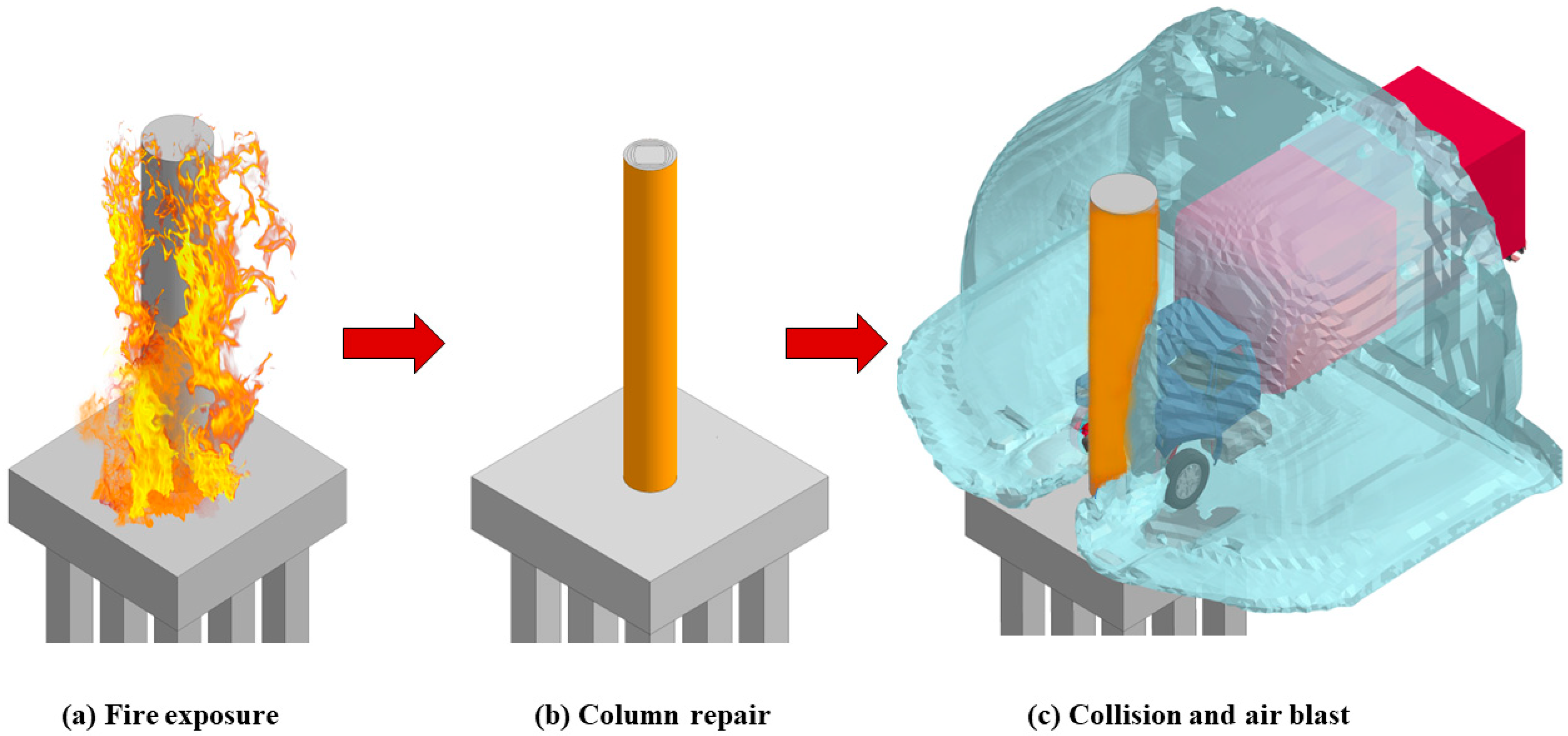
A modified version of the 8175-kg Ford F800 Single Unit Truck (SUT) finite element model, originally developed by the National Crash Analysis Center [36], was used to simulate vehicular impacts. The truck was assigned a velocity of 120 km/h, corresponding to the maximum speed limit commonly found on rural highways in the United States. According to NCHRP Report 645 [37], the structural response of bridge columns to air blasts should be assessed for scenarios where the scaled distance, Z, is less than 0.6 m/kg1/3, with the explosive charge weight expressed in terms of TNT equivalence. Drawing on estimates provided by the Federal Emergency Management Agency (FEMA) for potential terrorist attacks [38], a scaled distance of 0.25 m/kg1/3 was selected for this study. To accurately capture blast wave transmission through air and soil domains, the Multi-Material Arbitrary Lagrangian-Eulerian (MM-ALE) method in LS-DYNA was employed [32]. This approach is widely used for near-field blast simulations, where large mesh deformations could otherwise compromise the stability of explicit solvers [39]. Previous project work identified that a vehicle collision followed by an air blast represents the most critical loading sequence for these columns [18]. Before applying impact and blast loads, fire-damaged columns were retrofitted using various combinations of CFRP composites. The sequence of loading demands applied to the isolated bridge columns is shown in Figure 1.

Figure 1.
Bridge column and demand sequence.
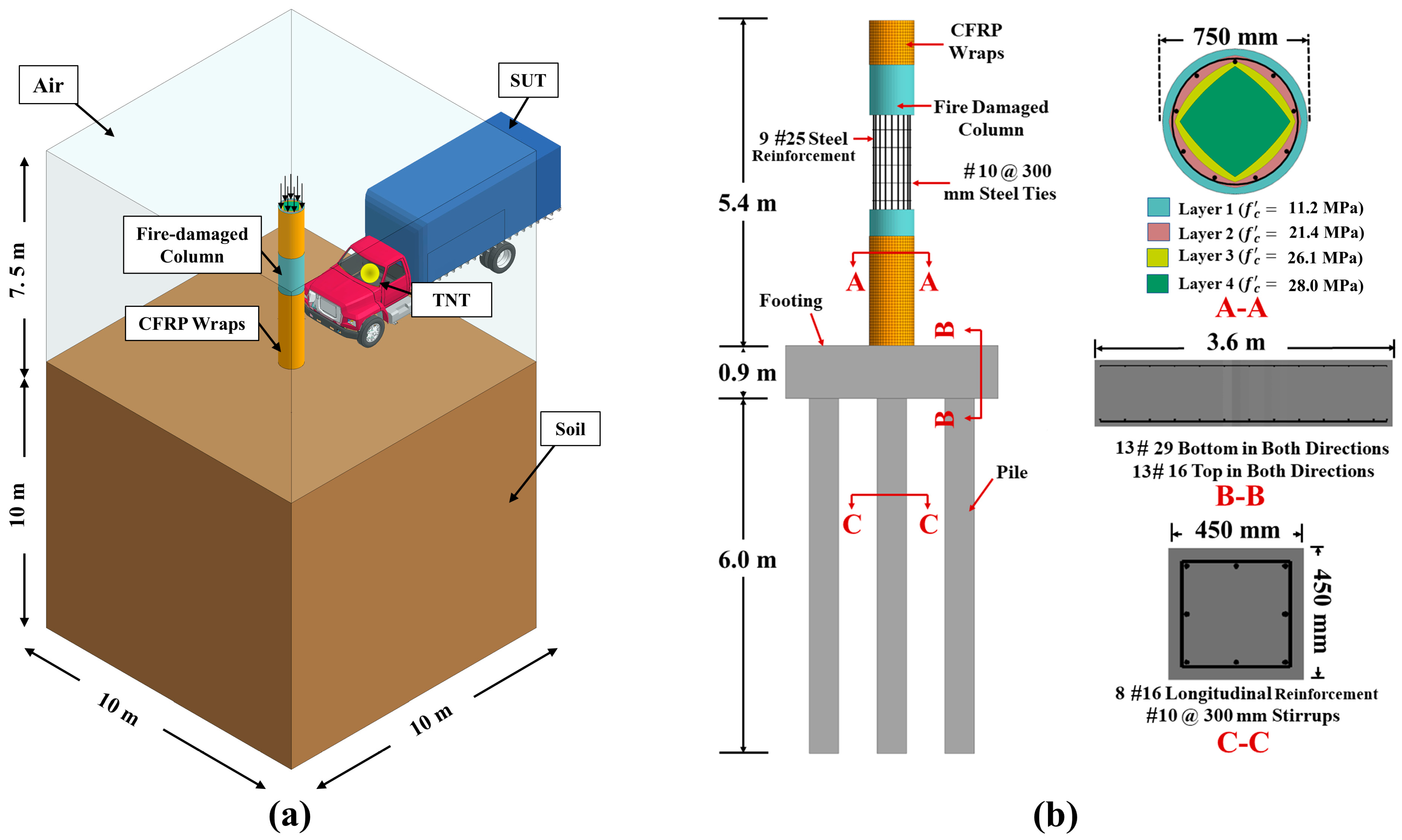
2.1.2. Model Coupling and Boundary Conditions
The isolated bridge pier column and its foundation system matched models developed during an earlier phase of the research [18]. More specifically, the reinforced concrete (RC) column, spread footing, and supporting piles were initially designed following a Federal Highway Administration (FHWA) design example, as shown in Figure 2 [40]. In this configuration, the soil domain dimensions were selected to accurately capture soil-structure interaction effects and to minimize interference from reflected blast waves [41]. Similarly, the surrounding air domain was sized to ensure realistic blast wave propagation around the column. Interaction between the structural components and the surrounding air, soil, and explosive materials was defined using LS-DYNA’s Lagrangian in Solid coupling approach. Columns with diameters of 750 mm, 1050 mm, and 1350 mm were analyzed, with their designs following the AASHTO LRFD Bridge Design Specifications [4]. Consistent with previous studies, contact between the structure, the soil domain, and the Single Unit Truck (SUT) model was defined using the Automatic Surface to Surface contact algorithm [32,42,43]. To address potential computational instabilities during blast wave simulation, the Boundary-Non-Reflecting option in LS-DYNA was applied at the edges of the air and soil volumes [32]. Columns were modeled as propped cantilevers, with the base rigidly fixed to the footing and the top restrained against lateral translation to represent the superstructure’s effect. An axial load equivalent to 6% of the column’s nominal capacity was applied before dynamic loading to simulate the superimposed dead load. Contact between the SUT and CFRP-retrofitted surfaces was modeled using a segment-based, penalty-type Automatic Surface to Surface algorithm, with static and dynamic friction coefficients set to 0.30 [32,43,44,45]. The interaction between the blast wave and the retrofitted columns was again simulated using LS-DYNA’s Constrained Lagrangian in Solid method, with penalty-based coupling (CTYPE = 4) enabled to allow for CFRP material erosion during loading [32].

Figure 2.
Finite Element Model Components: (a) Column, Surrounding Air and Soil Domains, and Single Unit Truck (SUT); (b) Retrofitted Column and Foundation System.
2.2. Material Properties and FE Models
2.2.1. Concrete and Steel Reinforcement
The concrete in both the column and foundation system was modeled using LS-DYNA’s default solid element formulation, while the internal steel reinforcement was represented using Hughes-Liu beam elements [32,42]. Concrete and steel discretization matched what was utilized in previous research [18]. The Continuous Surface Cap Concrete (MAT-159) nonlinear constitutive model was used for the concrete, as it accounts for strain hardening and softening under high loading rate demands [42,46]. An erosion parameter of 1.10 was selected based on available literature, which indicates that elements having a principal strain of 10% or greater will be deleted [32,42]. The Piecewise Linear Plasticity (MAT-24) constitutive model was adopted for steel reinforcement, with strain rate coefficients set to Cs = 40 and Ps = 5 as recommended in previous studies [18,42]. A perfect bond between steel reinforcement and concrete was assumed and modeled using LS-DYNA’s Lagrangian in Solid option. Concrete and steel material properties were selected in accordance with previous research studies and listed in Table 1 [42,47,48].

Table 1.
Concrete and steel reinforcement material model inputs.
2.2.2. Soil
To realistically model the interaction between the pile foundation system and the surrounding soil, a soil volume was incorporated into the finite element model. The soil domain was modeled using LS-DYNA’s Arbitrary Lagrangian-Eulerian (ALE) multi-material solid element formulation (ELFORM = 11), with the FHWA soil material model (MAT-147) adopted based on guidance from previous studies [18,32,49]. Initially developed by the Federal Highway Administration (FHWA), this material model features a smooth hyperbolic yield surface combined with a first-order Mohr-Coulomb failure criterion, where failure is defined by the exceedance of combined shear and effective normal stresses beyond the yield surface [49]. The input parameters for the soil model in this study were sourced from existing literature and the LS-DYNA user manual and are summarized in Table 2 [32,41,49]. Further information regarding soil modeling techniques and soil-structure interaction considerations can be found elsewhere [18,22,35,50,51,52,53].
Table 2.
FHWA soil material model inputs.
2.2.3. Air Volume and Explosive
The surrounding air domain was modeled using ALE one-point multi-material solid elements, employing the NULL material model (MAT-09) along with LS-DYNA’s Linear Polynomial (LP) Equation of State (EOS) [18,32]. The selected polynomial EOS coefficients (C0 to C6), the initial internal energy per unit reference volume (E0,air), and the air density are listed in Table 3, based on values reported in prior studies [54]. To represent the explosive charge, LS-DYNA’s Initial Volume Fraction Geometry keyword was used to embed a spherical TNT charge within the air domain, with the center of detonation specified using the Initial Detonation option [32]. The explosive material was defined using the High Explosive Burn model (MAT-008) combined with the Jones-Wilkins-Lee (JWL) EOS [18,32]. The properties of TNT and the associated EOS parameters, including E0,v (detonation energy per unit volume), and the coefficients A, B, R1, R2, and ω for the JWL EOS, are summarized in Table 4 and were selected based on previous research [54].
Table 3.
Null material model and Linear Polynomial (LP) EOS parameters.
Table 4.
High Explosive Burn material model and JWL EOS parameters.
2.2.4. CFRP Sheets
The CFRP wrap was modeled using Belytschko-Tsay four-node shell elements (ELFORM = 2) available in LS-DYNA [32]. The Part-Composite option was utilized to specify the number of CFRP layers, the corresponding through-thickness integration points, and the associated material properties [55,56,57]. Consistent with previous research, the Enhanced Composite Damage model (MAT-54) was selected to simulate the dynamic behavior of the CFRP [57,58,59,60]. This material model captures both tensile and compressive failure modes of the fiber and matrix, while delamination between composite layers is represented using the Chang-Chang failure criterion [32]. CFRP material properties were sourced from manufacturer data sheets for SikaWrap-301C ©, a widely used product in practical applications and prior studies [58,61]. The specific material properties adopted for the simulations are listed in Table 5.
Table 5.
CFRP sheets material properties (SikaWrap301-C).
2.2.5. CFRP Rods
The CFRP reinforcement was modeled using LS-DYNA’s Piecewise Linear Plasticity material model (MAT-24) in combination with round, two-node Hughes-Liu beam elements [32]. Previous studies have shown that dynamic strength enhancements due to high strain rates can generally be neglected for CFRP materials; therefore, no strain rate effects were incorporated into the model [58,62]. Following the approach used for steel reinforcement, CFRP rods were bonded to the surrounding concrete using LS-DYNA’s penalty-based Lagrangian in Solid algorithm [18,32,42]. Material properties for the CFRP rods were obtained from manufacturer data sheets for Sika CarboDur© Rods and are provided in Table 6.
Table 6.
CFRP Rods material properties (Sika CarboDur).
2.2.6. Bonding Agent
The epoxy layer, which is widely used to bond CFRP materials to structural elements, was modeled using LS-DYNA’s Automatic Surface-to-Surface Tie-Break contact algorithm, following the approach adopted in previous studies [32,57,58,59]. In this method, failure is predicted when the following criterion is satisfied:
where: and represent the tensile normal and shear stresses, respectively, and NFLS and SFLS correspond to the tensile normal and shear failure stresses. Based on values reported in earlier research, the failure stresses were set to 32 MPa for NFLS and 29.4 MPa for SFLS [58,59,63].
2.3. FE Model Validation
Earlier phases of this research project successfully validated the finite element models used to simulate fire, vehicular collision, air blast, and their cumulative multi-hazard effects using experimental data reported in the literature [18,22,50,51]. However, no experimental studies were identified that investigated the behavior of fire-damaged and subsequently repaired RC structural elements subjected to either isolated or combined impact and blast events. As a result, the finite element models of the retrofitted RC columns were validated using separate, previously published impact and blast experiments. The first validation case involved assessing the performance and failure mechanisms of a CFRP-wrapped RC pier column subjected to impact using a pendulum test setup [64]. The second test evaluated the dynamic response of a GFRP-strengthened RC panel exposed to air blast loading [65]. Validation criteria included qualitative damage patterns and quantitative comparisons of impact forces, displacement histories, and peak pressure values. Good agreement was observed across all comparisons, with differences within acceptable engineering margins (typically < 10%), confirming the reliability of the developed models.
2.3.1. CFRP Wrapped Columns Under Impact
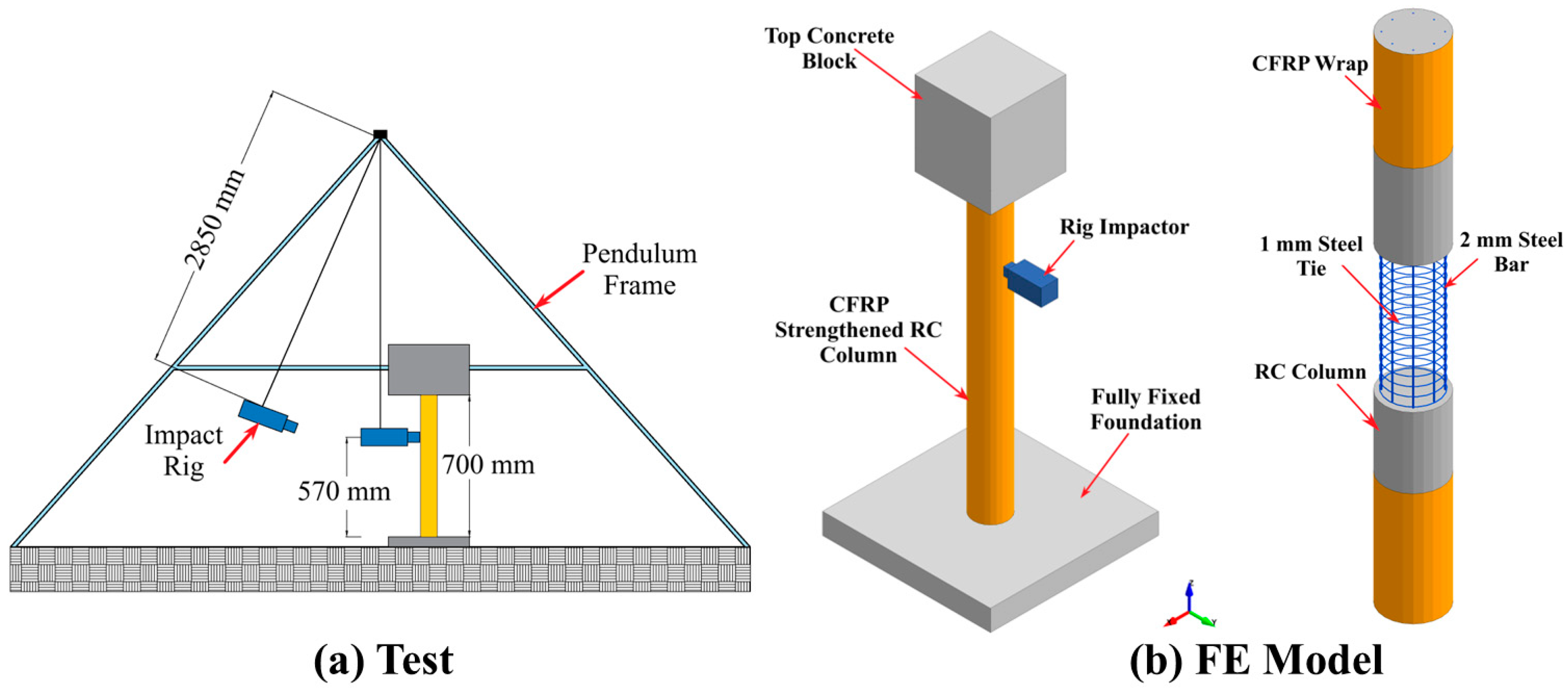
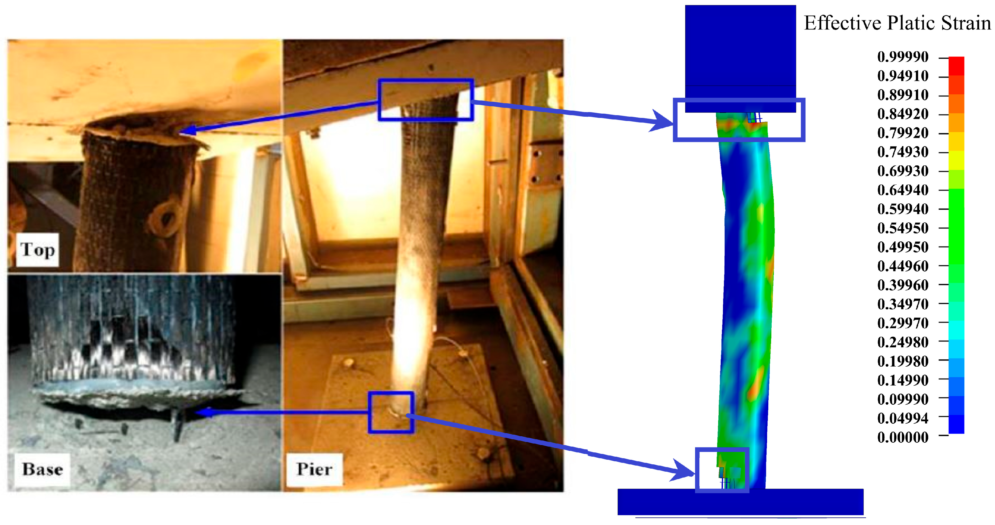
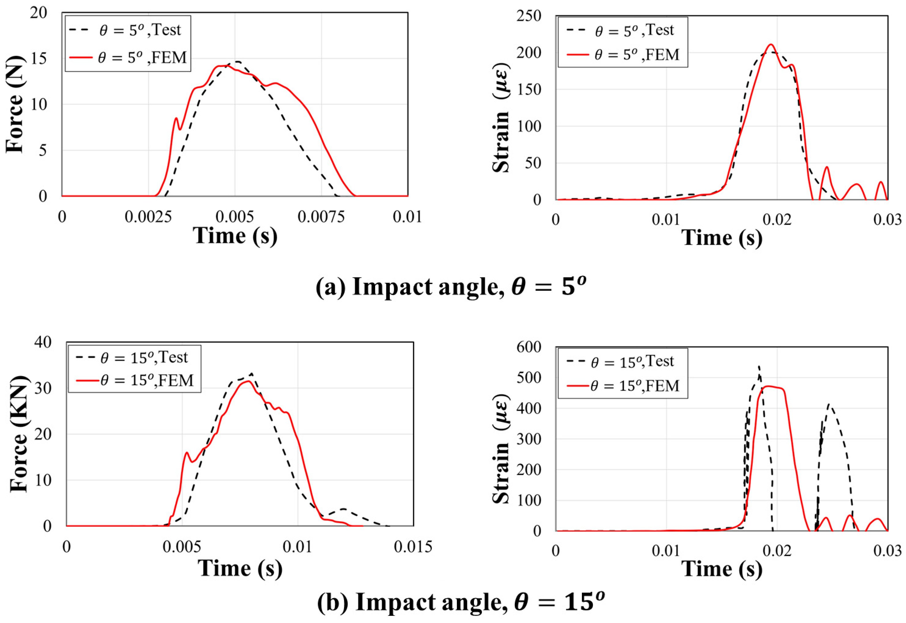
The impact behavior of a reduced-scale, CFRP-strengthened, round reinforced concrete (RC) bridge pier column was evaluated using a pendulum testing setup [64]. The tested column has a 78 mm diameter and a 700 mm height and was reinforced with eight longitudinal steel bars, each 2 mm in diameter, along with 1 mm-thick transverse steel ties spaced at 12.5 mm intervals. A 0.13 mm-thick externally bonded CFRP sheet was wrapped around the full surface of the column. To simulate dead and live axial loads, a 173.6 kg concrete block was placed atop the column. As illustrated in Figure 3, the pendulum apparatus featured a 2850 mm swing radius and supported a 60 kg impactor, which struck the column at a height of 570 mm above a 25 mm thick steel base plate. The impact energy was progressively increased by enlarging the pendulum swing angle (θ) from the vertical in 5° increments until failure occurred. The numerical simulation of the pendulum tests followed the modeling strategy outlined in Section 2.1. The impactor and the concrete block were modeled using LS-DYNA’s Rigid material model (MAT-20) to improve computational efficiency [32]. Contact between the impactor and the CFRP-strengthened column was defined using the Automatic Surface to Surface penalty-based algorithm, while the interaction between the CFRP wrap and the column surface was modeled using the Automatic Surface to Surface Tie Break. LS-DYNA’s Interface Springback command was employed to transfer stresses, strains, and permanent deformations from one impact stage as initial conditions for the next. The final damage patterns predicted by the model closely matched the experimental observations, with shear failures developing at the column ends when θ reached 25° (Figure 4). Furthermore, comparisons between the simulated and experimental impact forces and reinforcement strains showed strong agreement, as illustrated in Figure 5.
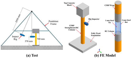
Figure 3.
Pendulum test setup and corresponding FE model.
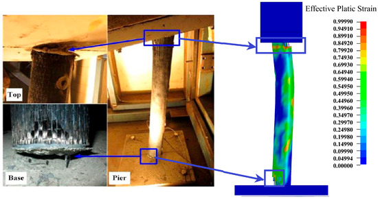
Figure 4.
Test and FE model failure and damage patterns [64].
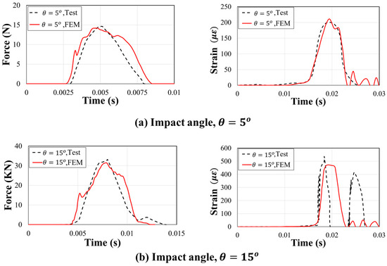
Figure 5.
Test and FE model—impact force and strain time histories: (a) ; (b) .
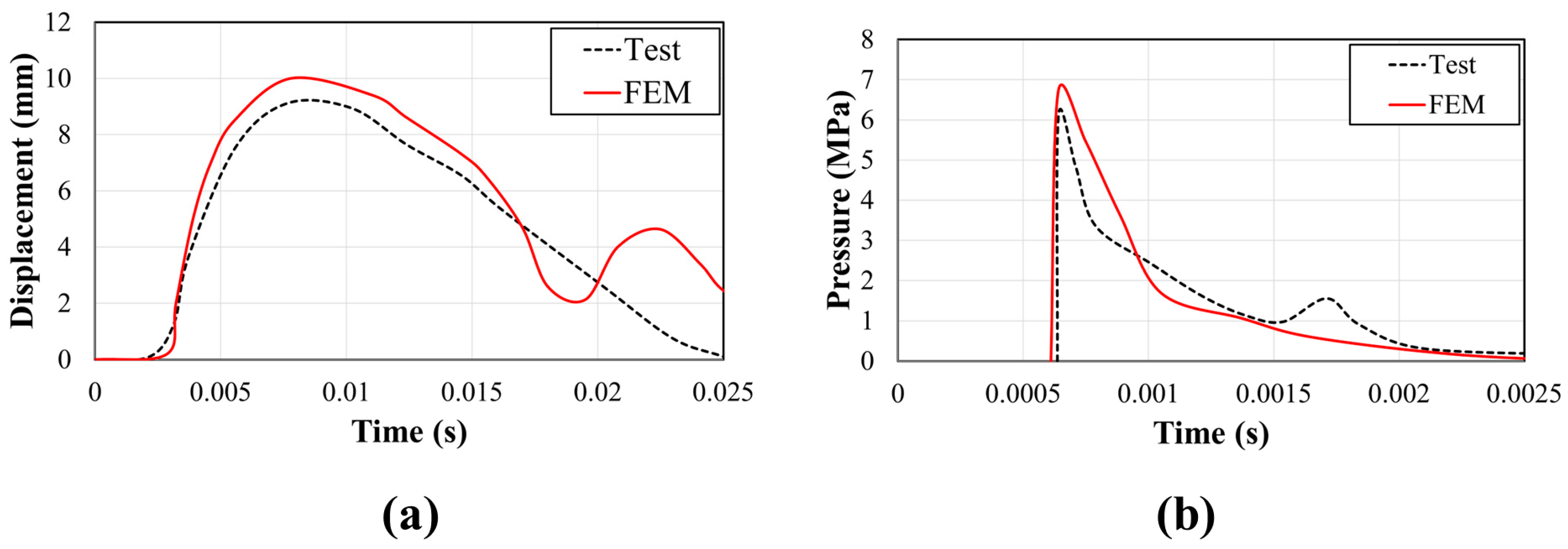
2.3.2. GFRP Strengthened RC Panel Under Blast
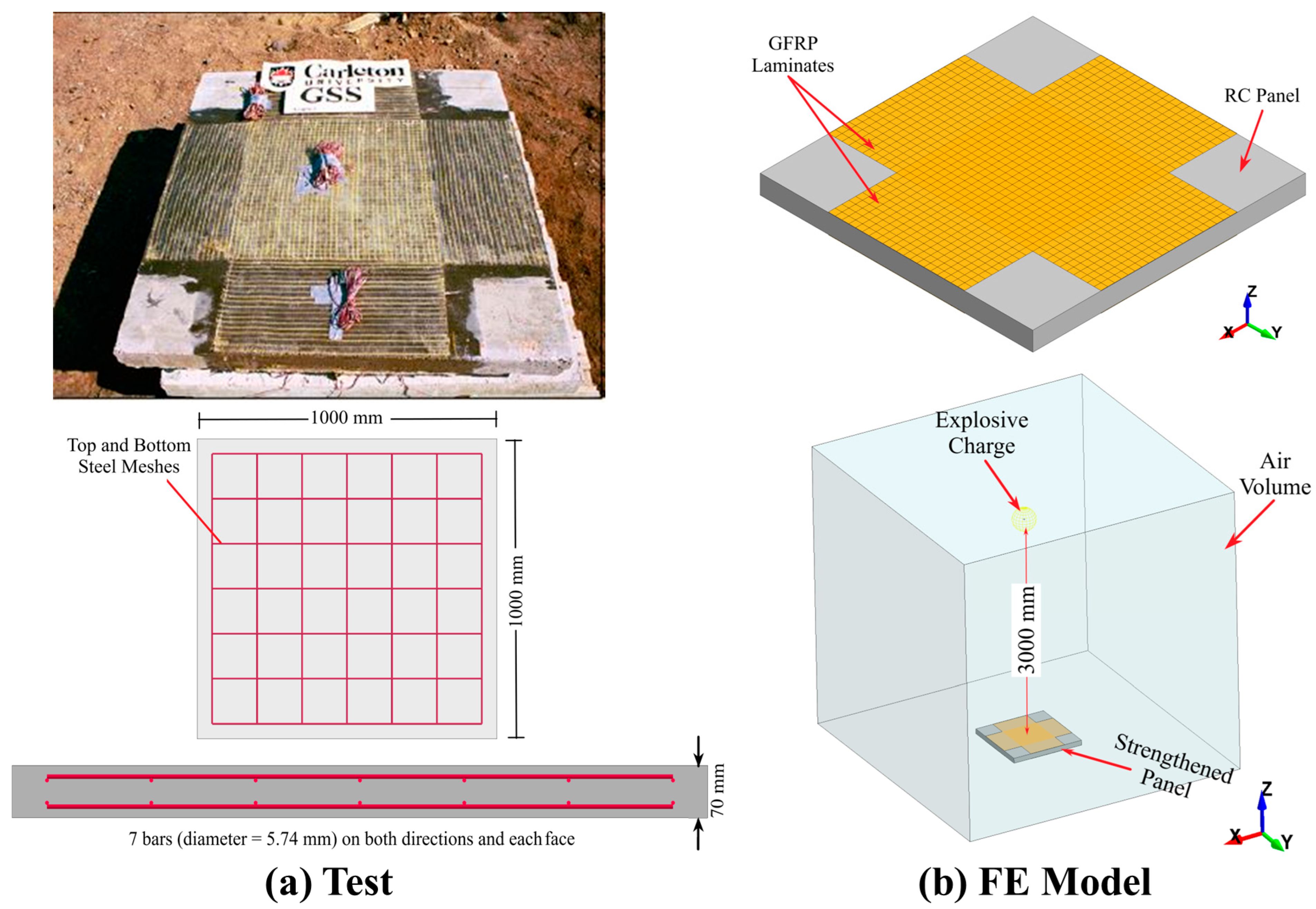
A blast test conducted on a reinforced concrete (RC) panel strengthened with externally bonded glass fiber reinforced polymer (GFRP) sheets was also used to validate the numerical model [65]. As depicted in Figure 6, RC panels measuring 1000 mm by 1000 mm by 70 mm were subjected to a blast generated by a 33.4 kg ANFO explosive charge positioned 3000 mm from the panel surface. Each panel was reinforced with two 500 mm wide, 1.3 mm thick GFRP sheets bonded externally to both faces. The panels and the surrounding blast environment were modeled following the simulation approach outlined earlier in this study. The GFRP laminates were represented using shell elements. The interface between the RC panel and the GFRP sheets was modeled with LS-DYNA’s Automatic Surface to Surface Tie Break algorithm, incorporating failure criteria based on published epoxy tensile strength values [32]. Reflected pressure and midspan displacement time histories from both the experiment and the simulations were compared, as shown in Figure 7. The results demonstrated good agreement, with peak displacement discrepancies of around 10%. Calibration efforts primarily focused on matching the first peak displacements. Likewise, positive phase pressures, which are critical for blast-resistant structural design [66], also showed a strong correlation between the experimental and numerical results.
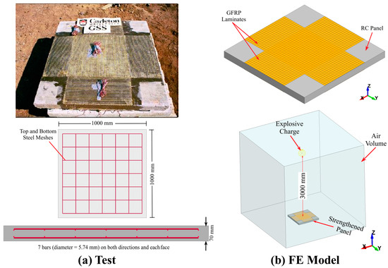
Figure 6.
Blast test setup and corresponding FE model [65].
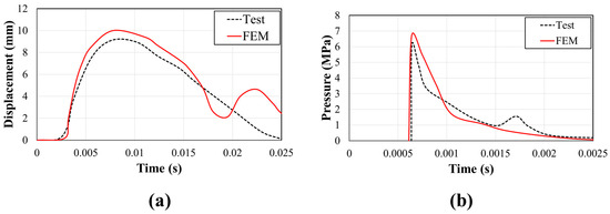
Figure 7.
Test and FE model—time histories: (a) displacement; (b) pressure.
2.4. Numerical Study
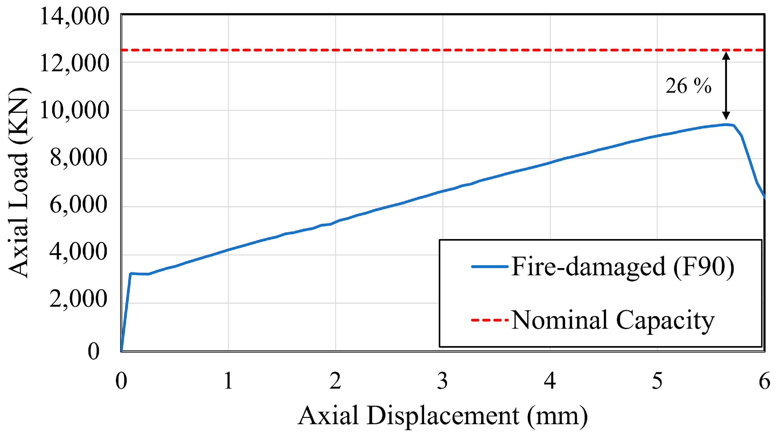
To study the effectiveness of various retrofitting schemes, a 750-mm diameter column, which is assumed to be more vulnerable to the imposed extreme demands, was initially investigated. The entire periphery of the column was exposed to a 90-min fire (i.e., F90), following ISO-834 [26]. Push-down analysis was then performed to assess post-fire column residual capacity. As shown in Figure 8, the applied axial load steadily increased until failure occurred, indicated by an abrupt drop in load-carrying capacity. This figure illustrates that the axial displacement increases with increasing applied load due to the stiffening effect. During this stage of loading, the material and structural elements align more effectively under the load, enhancing the load-bearing capacity. This effect persists until the column reaches a critical displacement, which was approximately 5.7 mm in our analysis. Beyond this displacement threshold, the column experiences a reduction in load-bearing capacity. This decline occurs due to the onset of material failure mechanisms such as buckling, cracking, or yielding of reinforcement, which compromise the structural integrity of the column. As illustrated in Figure 8, the ratio between residual and nominal capacities was 26%, which indicated that the column maintained 74% of its design capacity after fire damage was imposed. The retention of this relatively high capacity can be attributed to the limited fire exposure, which helped reduce core temperature rise and preserve the integrity of the concrete and reinforcement. This ratio was used as a fundamental tool for examining the studied retrofit scheme.
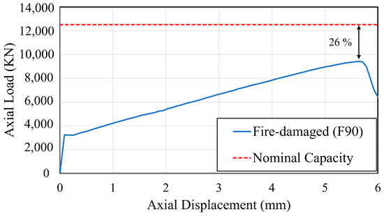
Figure 8.
Load-displacement curve—750 mm-diameter column under F90 fire.
2.4.1. Design of Retrofit Schemes
While the initial cost of FRP retrofitting may be higher than other methods, such as steel or concrete jacketing, its reduced labor requirements, rapid installation, ease of implementation, and high durability make FRP a preferred option for bridge retrofit applications [20,67,68]. The selected CFRP retrofit schemes in this study, full-height, partial-height, and hybrid wrapping, were designed to explore the impact of confinement extent and targeted strengthening on fire-damaged columns. Full-height wrapping provides comprehensive confinement, partial-height wrapping reflects limited repair scenarios, and the hybrid scheme addresses combined flexural and shear demand. These methods were informed by previous experimental and numerical studies focused on damage localization and repair feasibility [23,64,69]. Other techniques, such as steel jacketing, were not adopted due to lower fire resilience and practical limitations for rapid field application.
As previously stated, two retrofitting strategies were implemented in this study. The first involved wrapping fire-damaged columns with externally bonded carbon fiber-reinforced polymer (CFRP) sheets, while the second adopted a hybrid method combining CFRP sheets with near-surface-mounted (NSM) CFRP bars. Typically, the number of CFRP layers required for repair is determined by the extent of damage. For the first scheme, four CFRP thicknesses () were evaluated: 0.5 mm (three layers), 1 mm (six layers), 1.5 mm (nine layers), and 2 mm (twelve layers). These thicknesses were selected based on preliminary push-down analyses. Specifically, the number of CFRP layers was chosen to ensure that the column’s residual axial capacity approached or exceeded its original nominal design capacity. The estimated residual capacities associated with each CFRP thickness are presented in Figure 9. As expected, results showed that column residual strength increased with the addition of CFRP layers; however, beyond twelve layers (2 mm), no further improvement was observed. Consequently, the number of CFRP layers was limited to twelve. Similar to CFRP wrapping, the number of NSM bars for retrofitting is typically based on the severity of damage. Following recommendations from previous studies, the CFRP longitudinal reinforcement ratio for this research was selected within the range of 0.15% to 1% [70,71].
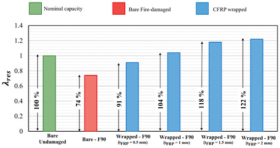
Figure 9.
Residual axial load-carrying capacity—750 mm-diameter column under F90 fire.
2.4.2. Selected Study Matrix
As previously described, two main CFRP retrofitting schemes were evaluated. The first scheme focused solely on external confinement and included four different CFRP wrap thicknesses. The second scheme, a hybrid approach, combined two CFRP wrap thicknesses with four longitudinal CFRP reinforcement ratios. A summary of the studied retrofitting configurations and their key parameters is provided in Table 7.
Table 7.
Summary of Studied Retrofitting Schemes and Key Parameters.
In the labeling convention used, “W” refers to external wrapping, “L” indicates the number of CFRP layers, and “R” corresponds to the number and diameter of the longitudinal CFRP reinforcement bars. For example, designates a column retrofitted using three layers of CFRP wrap under the full-wrapping scheme. Conversely, 4R12–3L identifies a hybrid configuration that includes four 12 mm diameter CFRP bars in combination with three CFRP wrap layers.
Additionally, denotes the total thickness of the CFRP wrap, while represents the volumetric reinforcement ratio associated with the embedded CFRP bars. These configurations were selected to investigate the effects of varying confinement intensity and axial reinforcement on post-fire column performance under sequential multi-hazard demands.
3. Results and Discussion
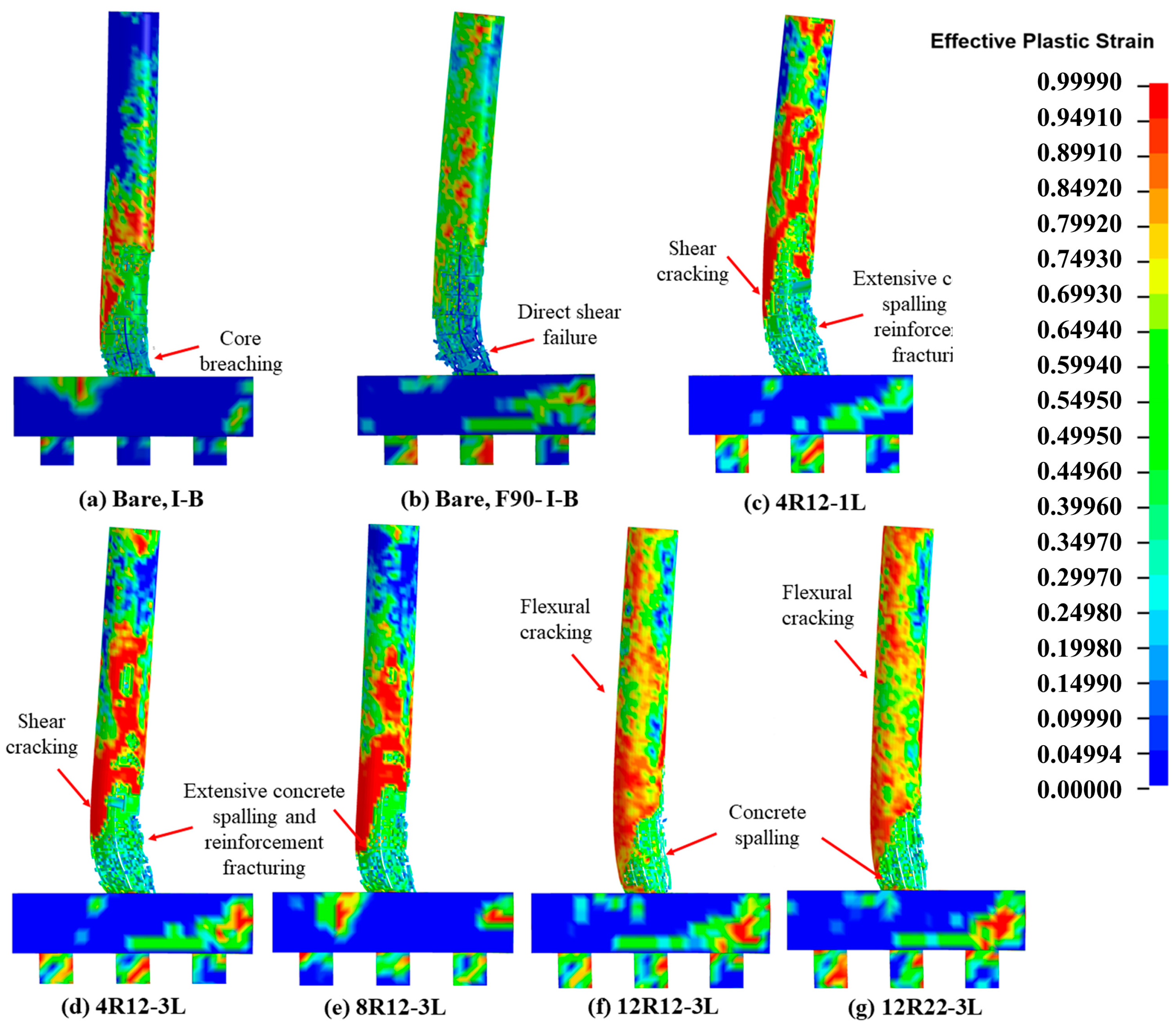
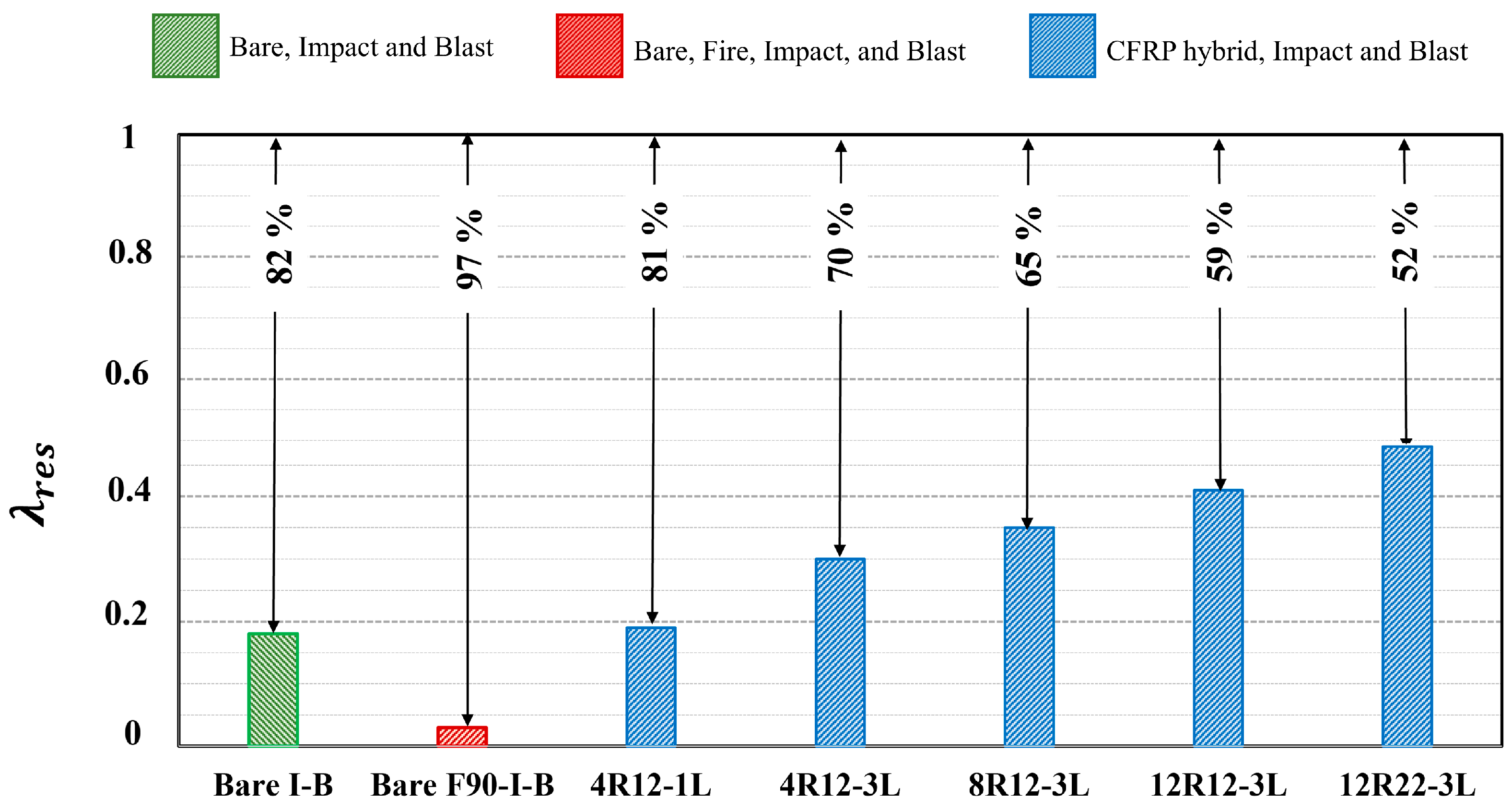
The performance of CFRP-repaired columns was evaluated under coupled impact and blast loads. To identify the effectiveness of selected retrofitting schemes, the performance of retrofitted columns was compared to bare, intact columns subjected to impact and blast (i.e., I-B) and to bare columns under post-fire impact and blast (i.e., F90-I-B). Performance assessment encompassed investigating crack propagation, damage levels, final damage states, permanent sets, volume of spalled concrete, and residual capacities. CSC-Concrete LS-DYNA depicts cracks when an element’s effective plastic strain approaches 1.0, visually represented using red strain contours. Maximum kinetic energy was also considered in this evaluation, as it provides a measure of the energy absorbed by the CFRP during impact. The kinetic energy values were extracted using LS-DYNA’s Material Summary (MATSUM) command [32].
3.1. Fully CFRP Wrapped Columns
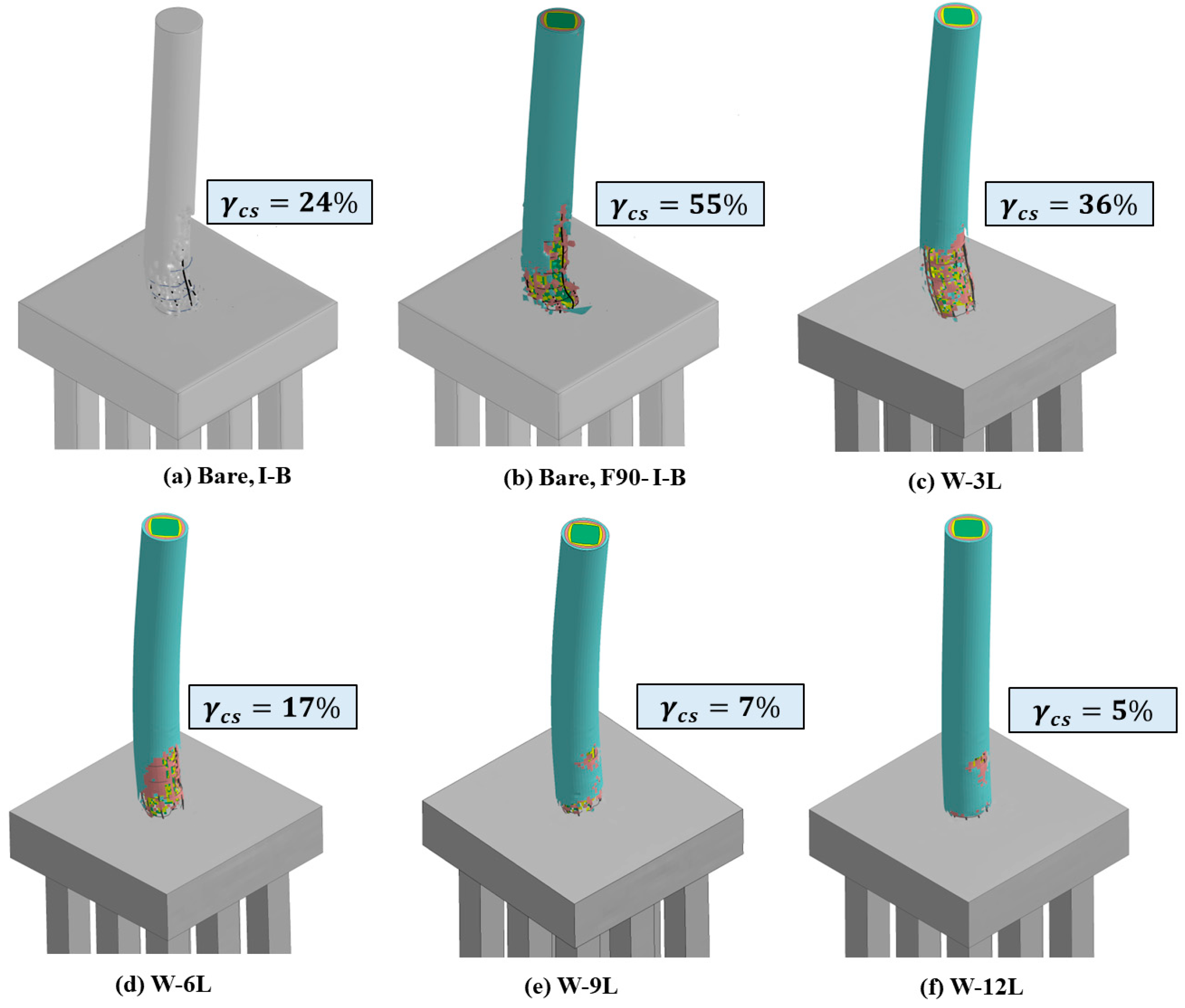
Crack propagation and damage patterns for all analyzed columns are presented in Figure 10. The results indicate that, without fire exposure, the core of the intact bare column was fully penetrated, whereas the bare fire-damaged column experienced a direct shear failure, highlighting a high potential for bridge collapse. As shown in the figure, increasing CFRP wrap thickness reduced cracking extent; however, no significant improvement was observed beyond a thickness of 1.5 mm (nine layers). Additionally, plastic hinge formation was apparent in the W-3L and W-6L configurations, reflecting localized concrete spalling, core cracking, reinforcement yielding, and bar buckling. These observations suggest that greater CFRP thickness is necessary to enhance structural performance and suppress damage propagation.
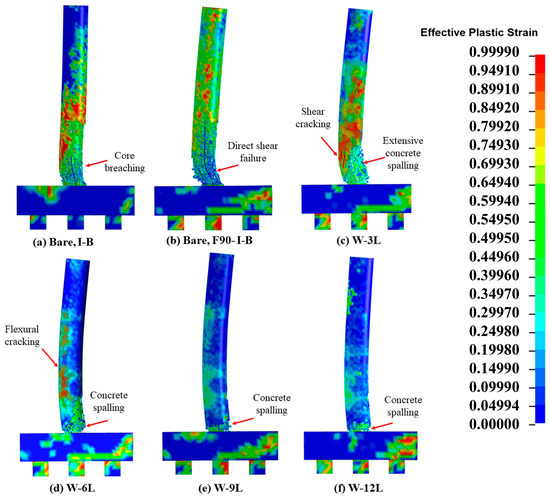
Figure 10.
Damage propagation—bare and fully-wrapped columns.
Figure 11 shows the final damage states and volumes of spalled concrete () for both bare and CFRP-wrapped columns. The results clearly demonstrate that CFRP wrapping substantially mitigates concrete spalling. While the W-3L column exhibited severe spalling, the W-6L configuration experienced more localized and less extensive damage. In contrast, columns wrapped with 1.5 mm and 2.0 mm thick CFRP showed minimal visible damage, suggesting they may remain operational with only minor post-event repairs.
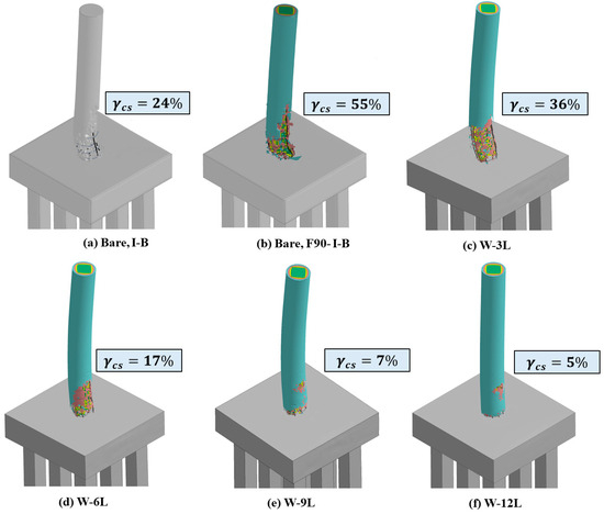
Figure 11.
Final damage states and volume of spalled concrete—the bare and fully-wrapped columns.
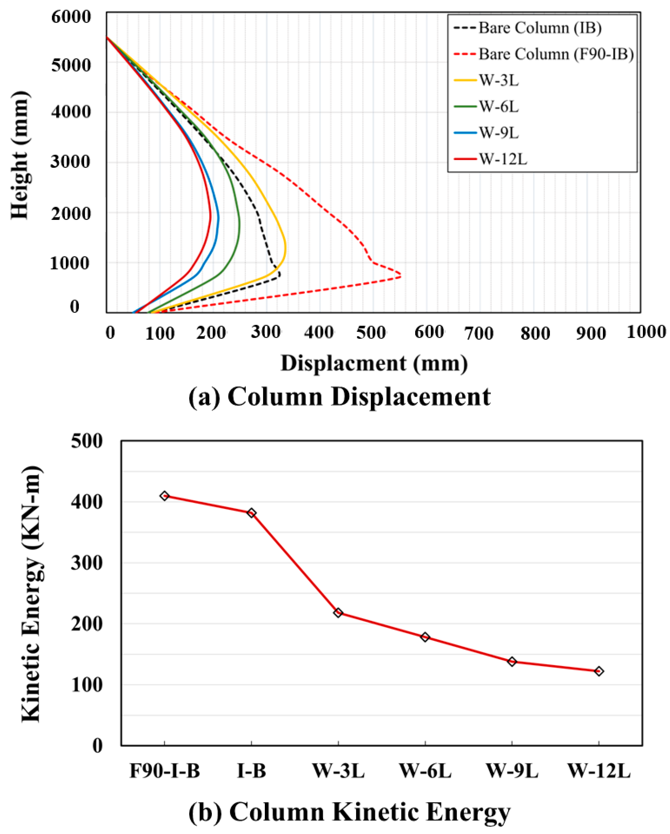
Displacement responses and corresponding maximum kinetic energies are presented in Figure 12. As expected, CFRP wrapping significantly reduced lateral displacements, with increased wrap thickness leading to further reductions and enhanced energy absorption. For instance, columns retrofitted with 0.5 mm-thick CFRP exhibited peak displacements and kinetic energy values approximately 40% and 53% lower, respectively, than those of the baseline fire-damaged bare column. As previously noted, increasing the CFRP thickness from 1.5 mm to 2.0 mm yielded only a marginal improvement. Moreover, columns with thicker CFRP wraps displayed more uniform displacement profiles. Based on these observations, nine CFRP layers (1.5 mm total thickness) were deemed sufficient to mitigate the combined effects of impact and blast following fire exposure.

Figure 12.
Displacements and kinetic energies—bare and fully-wrapped columns.
Figure 13 presents the residual axial load-carrying capacities () of both bare and CFRP-strengthened columns. Consistent with earlier findings, increased significantly with CFRP thickness up to 1.5 mm, beyond which additional layers had minimal influence.
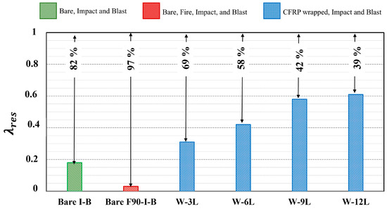
Figure 13.
Residual axial load capacity—bare and fully-wrapped columns.
3.2. Partially CFRP Wrapped Columns
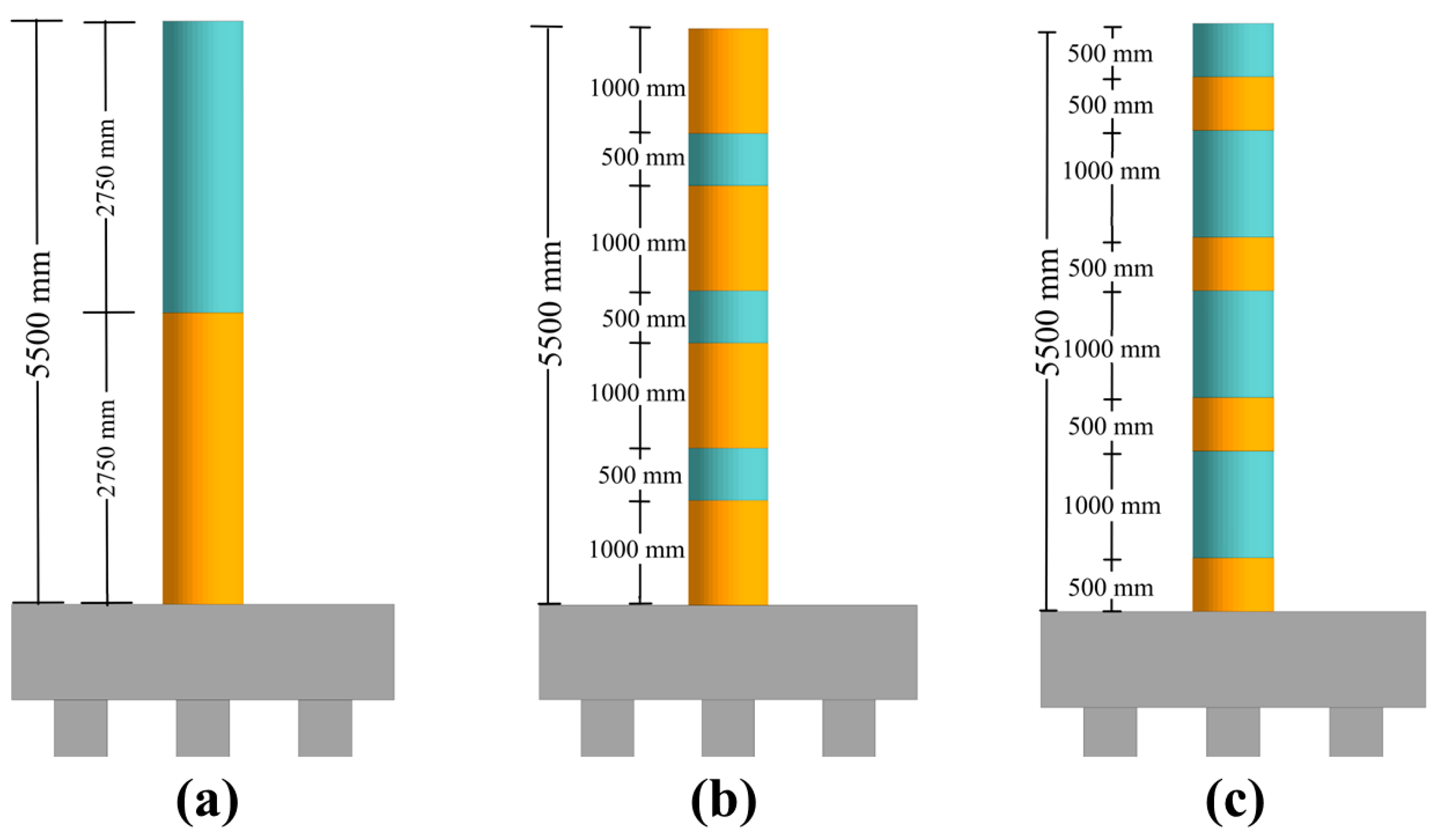
Additional analyses were performed to evaluate the effectiveness of partial and intermittent CFRP wrapping on column performance. These investigations were motivated by previous studies suggesting that partial wrapping can effectively reduce structural demands under various loading conditions [69,72,73]. As shown in Figure 14, three configurations were examined, each utilizing nine CFRP layers (). The first configuration involved wrapping the lower half of the column height (HH-9L), the second applied intermittent wraps using 1000 mm-wide strips (I1000-9L), and the third used 500 mm-wide intermittent strips (I500-9L). The performance of each scheme was assessed relative to that of the fully wrapped column (W-9L).
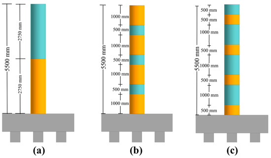
Figure 14.
Partially wrapped columns: (a) HH-9L; (b) I1000-9L; (c) I500-9L.
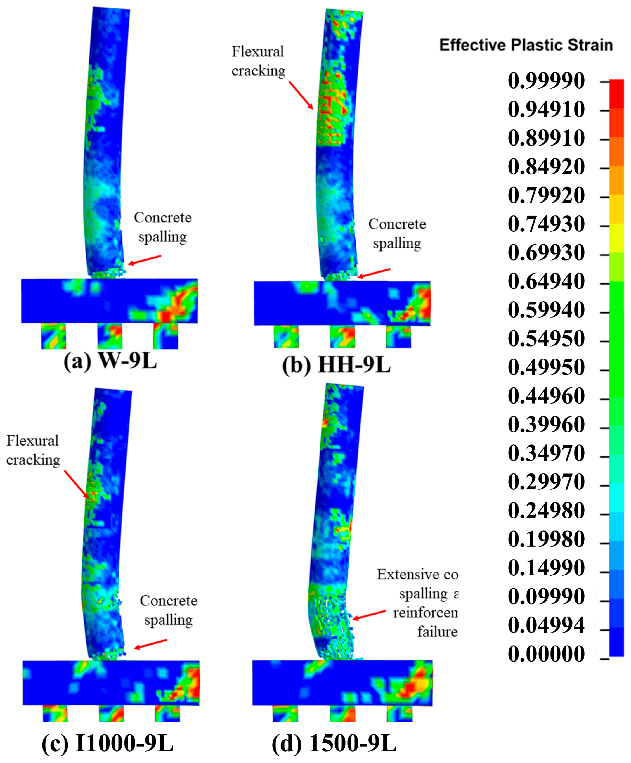
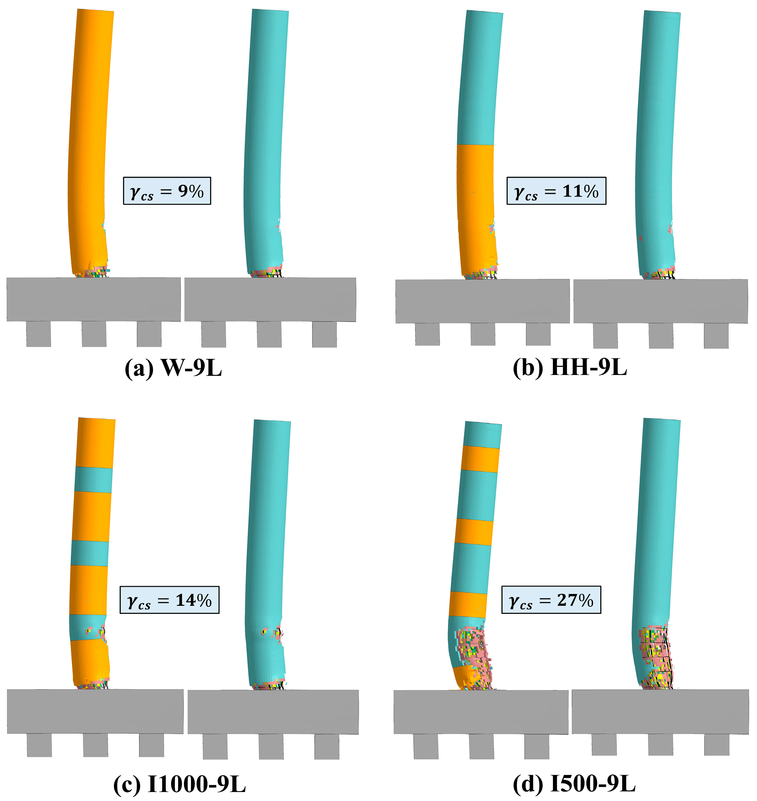
Effective plastic strain contours were used to evaluate crack propagation along the column height, as shown in Figure 15. For the HH-9L configuration, a higher number of flexural cracks developed along the unwrapped upper half of the column. In the I1000-9L case, the cracking intensity was comparable to that of the fully wrapped column, indicating sufficient confinement. Conversely, the I500-9L configuration exhibited pronounced localized cracking within the impact zone. In all configurations, cracks extended into the foundation, highlighting the influence of base fixity on stress transmission. Final damage states and the corresponding spalled concrete volumes () are depicted in Figure 16. The W-9L, HH-9L, and I1000-9L columns exhibited similar damage levels and spalling volumes, suggesting that targeted wrapping near the impact region or intermittent wrapping schemes can effectively mitigate collision and blast consequences, allowing the columns to remain serviceable with only minor repairs.

Figure 15.
Damage propagation—bare and partially-wrapped columns.

Figure 16.
Final damage states and volume of spalled concrete—the bare and partially-wrapped columns.
Displacement trends and maximum kinetic energy values are presented in Figure 17. Significant reductions in both lateral displacement and kinetic energy were observed for the W-9L, HH-9L, and I1000-9L configurations. For example, the HH-9L column exhibited a 58% reduction in peak displacement and a 59% reduction in kinetic energy compared to the bare fire-damaged column. Similarly, the I1000-9L configuration achieved a 51% displacement reduction and a 54% decrease in kinetic energy. Notably, the displacement profiles along the lower 1000 mm of the column height were identical for both W-9L and HH-9L, underscoring the effectiveness of lower-half wrapping. In contrast, the I500-9L configuration showed smaller performance gains, with limited reductions in displacement and kinetic energy, indicating diminished effectiveness of narrower intermittent wraps. Based on these findings, both HH-9L and I1000-9L were deemed effective in mitigating the combined effects of impact and blast following fire exposure. These configurations also demonstrated improved residual axial capacity (), retaining 51% and 54% of the original load-carrying capacity, respectively.
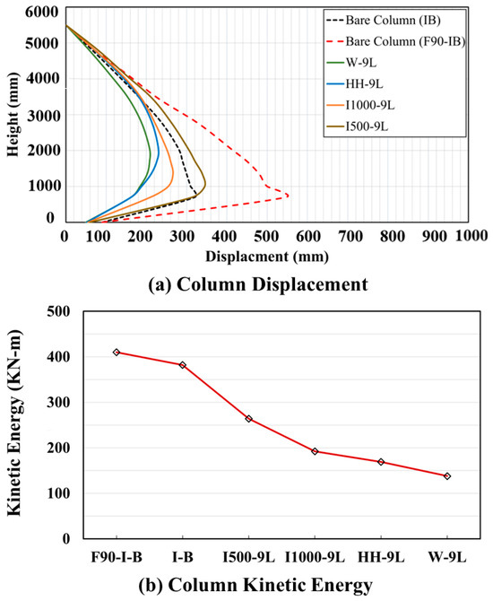
Figure 17.
Displacements and kinetic energies—bare and partially-wrapped columns.
3.3. Hybrid CFRP Retrofit
Figure 18 presents effective plastic strain contours for the hybrid retrofitting configurations. Minimal performance improvement was observed in the 4R12–1L case, which exhibited extensive cracking along the entire column height. Increasing the CFRP wrap thickness from 0.167 mm (single layer) to 0.50 mm (three layers) led to a modest reduction in surface cracking. When the number of CFRP bars was doubled, similar cracking patterns were observed, though with slightly less severity. As the CFRP reinforcement ratio increased while maintaining constant wrap thickness, the damage patterns transitioned from combined flexural-shear cracking at mid-height to predominantly flexural cracking. However, for the 12R12–3L and 12R22–3L configurations, no substantial differences in surface cracking were observed.
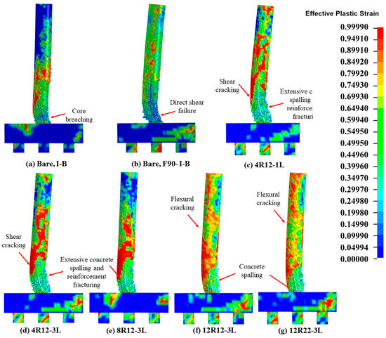
Figure 18.
Damage propagation—bare and hybrid-retrofitted columns.
Figure 19 depicts the final damage states and compares the volumes of spalled concrete (). Consistent with previous findings, significant concrete cover spalling was observed in the 4R12–1L and 4R12–3L configurations. For the other hybrid schemes, spalling levels were nearly indistinguishable. Although the extent of external damage appeared similar across most configurations, full core penetration occurred only in the 4R12–1L case. Consequently, all columns in this group would require substantial repair efforts to restore full serviceability.
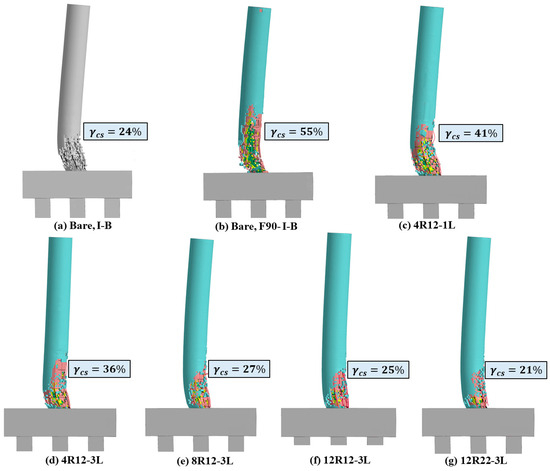
Figure 19.
Final damage states—bare and hybrid-retrofitted columns.
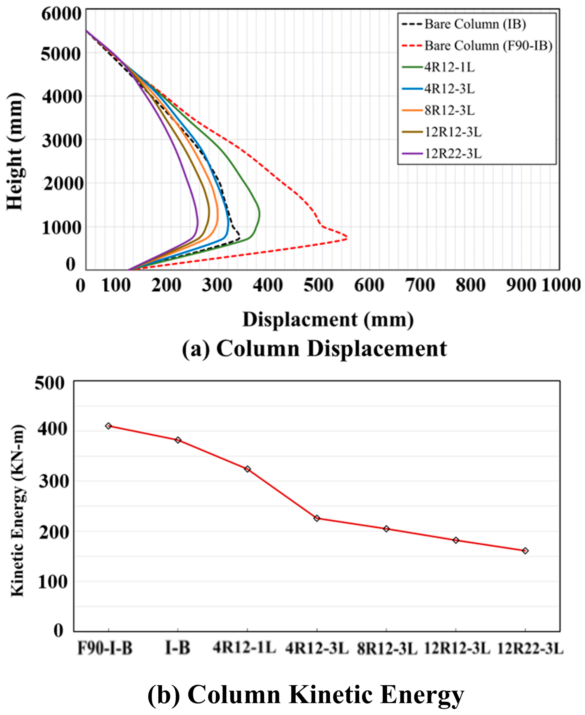
Displacement trends and maximum kinetic energy results are shown in Figure 20. Lateral displacements were significantly reduced through the use of hybrid retrofitting techniques. As expected, greater reductions in both displacement and kinetic energy were achieved with a thicker CFRP wrap (0.5 mm). For instance, the 4R12–1L configuration showed reductions of 34% in peak displacement and 22% in kinetic energy compared to the bare fire-damaged column. In the 4R12–3L case, these reductions increased to 46% and 45%, respectively, underscoring the superior performance of three CFRP layers over a single layer. Comparable reductions were also observed in the remaining hybrid configurations, largely due to the added stiffness from increased CFRP reinforcement. These findings suggest that increasing the CFRP reinforcement ratio effectively enhances lateral stiffness and energy absorption, although it has a limited impact on mitigating surface cracking and concrete spalling.
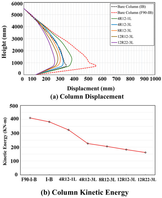
Figure 20.
Displacements and kinetic energies, bare and hybrid retrofitted columns.
The residual axial load-carrying capacities for the studied columns are demonstrated in Figure 21. Notably, lateral confinement significantly improved as the CFRP wrap thickness increased from 0.167 mm (one wrap) to 0.50 mm (three wraps), contributing to enhanced post-blast and post-impact structural performance.

Figure 21.
Residual axial load carrying capacities, bare and hybrid retrofitted columns.
3.4. Effect of Bridge Column Diameter
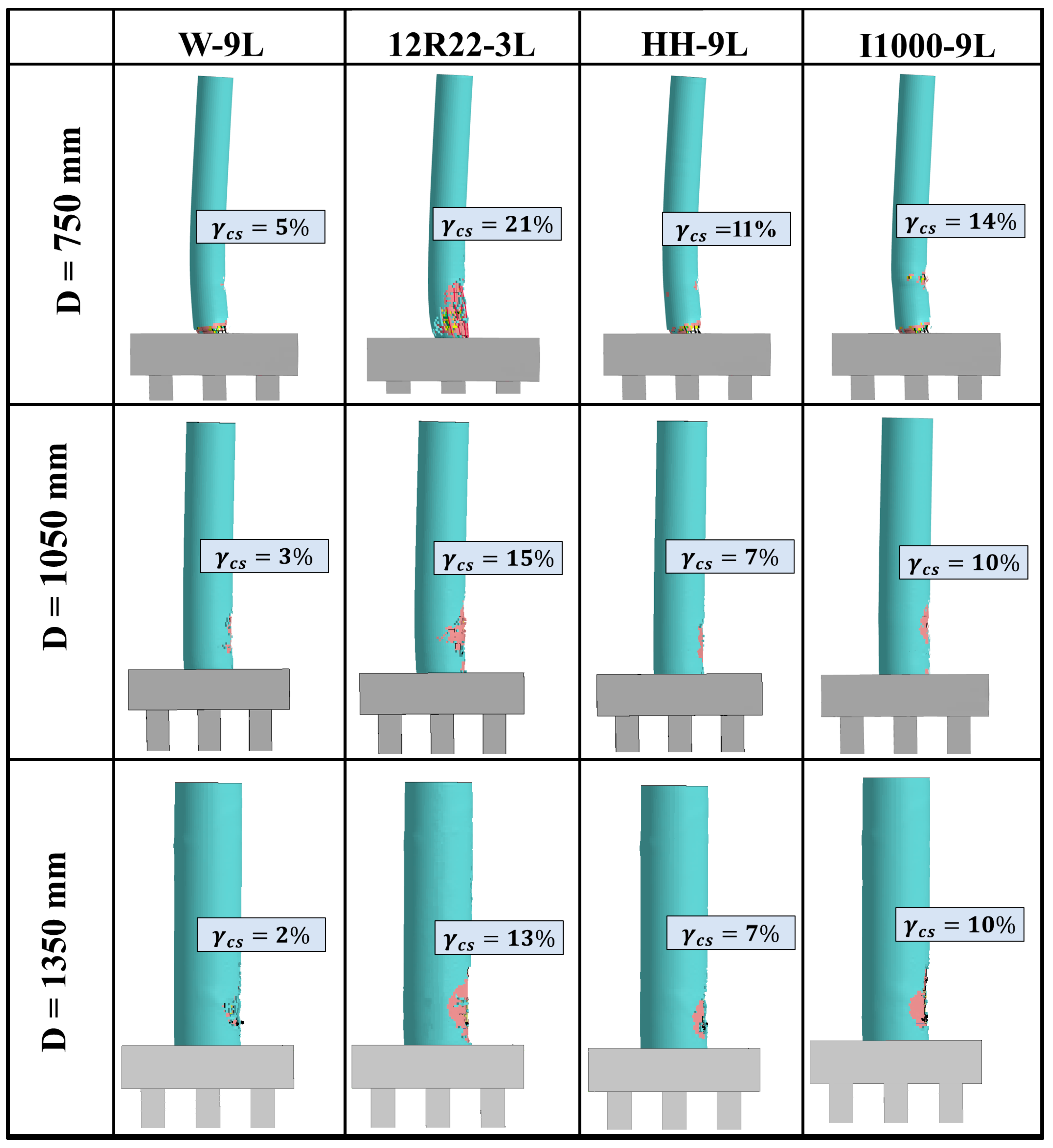
To more comprehensively evaluate the effectiveness of the previously studied retrofitting strategies, additional simulations were conducted on larger column diameters of 1050 mm and 1350 mm, with results compared to those from the 750 mm column. The most effective retrofitting schemes identified for the 750 mm column, namely W-9L and 12R22–3L, were selected for further analysis. Additionally, the HH-9L and I1000-9L configurations were included, as they had shown strong performance in reducing column response to combined impact and blast loads.
As anticipated, the larger diameter columns exhibited greater resistance to loading demands in their unrepaired state, with no direct shear failures observed. Similar to the results for the 750 mm columns, the W-9L configurations for both larger diameters showed minimal cracking, whereas 12R22–3L exhibited more extensive surface damage. For HH-9L, significant flexural cracking developed in the unwrapped upper portion of the column, while the wrapped lower section experienced only localized cracking similar in severity to that observed in the W-9L case. In the I1000-9L configuration, cracks extended into the unwrapped regions of the column, particularly near the impact zone, showing patterns consistent with those in W-9L and HH-9L.
Figure 22 illustrates the final damage states and relative volumes of concrete cover spalling for the studied columns. Consistent with earlier observations, columns retrofitted with W-9L, HH-9L, and I1000-9L exhibited only surface cracking and minor concrete cover spalling across all diameters, indicating that these columns could remain operational following minor repairs. In contrast, columns retrofitted using the 12R22–3L configuration experienced significantly greater concrete spalling compared to the other cases. Additionally, more severe damage was noted for 12R22–3L, including reinforcement failure in both the 750 mm and 1050 mm diameter columns. A plastic hinge formation was also observed at the base of the 750 mm column. These findings indicate that columns repaired with the 12R22–3L configuration would require extensive rehabilitation to restore full serviceability.

Figure 22.
Final damage states—all column diameters and selected retrofit schemes.
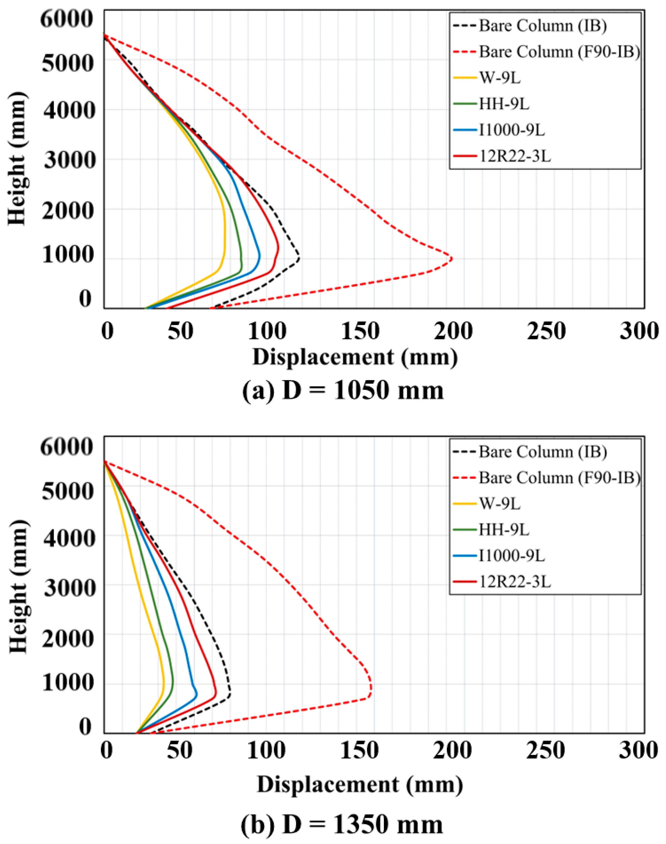
Permanent displacement profiles shown in Figure 23 demonstrate that all retrofitting techniques effectively reduce lateral displacements of the bridge columns. However, unlike the 750 mm diameter column, only minor differences in peak displacements were observed between the W-9L and HH-9L retrofitted cases for the 1050 mm and 1350 mm columns. This trend is attributed to the fact that larger-diameter bare columns inherently experience smaller displacements under the F90-I-B loading scenario.
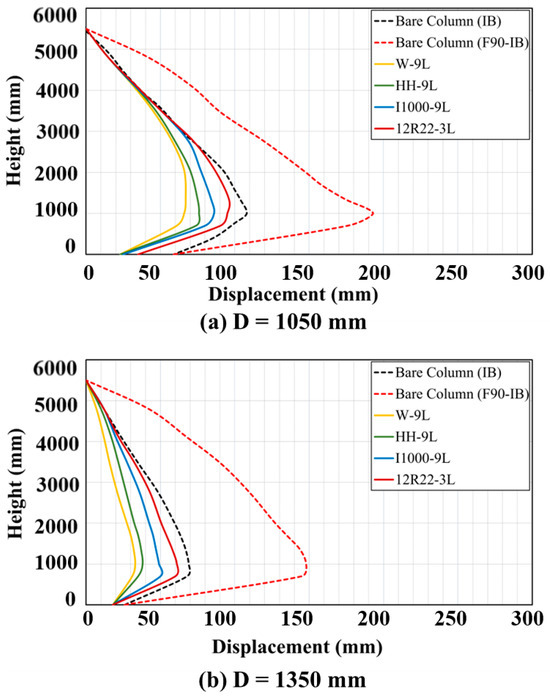
Figure 23.
Permanent displacements—bare and retrofitted columns: (a) D1050 mm; (b) D1350 mm.
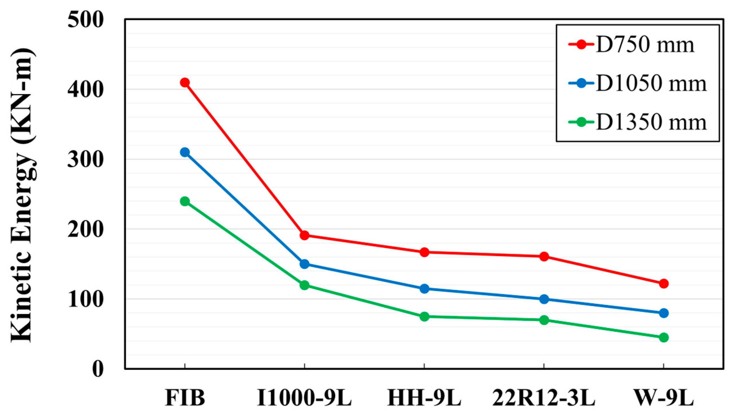
Figure 24 compares the maximum kinetic energy values for the different column configurations. In all cases, wrapping the full column height, as in the W-9L configuration, led to greater energy dissipation. However, for the 1050 mm and 1350 mm diameter columns, the improvements in energy absorption due to retrofitting were less pronounced compared to the 750 mm column. Among the larger columns, the W-9L, HH-9L, and 12R22–3L schemes produced similar levels of energy dissipation. These findings indicate that for larger bridge columns, full-height CFRP wrapping may not be necessary to achieve substantial improvements in impact and blast performance. Partial or hybrid retrofitting strategies, such as lower-half or intermittent wrapping, could provide sufficient protection while offering more efficient and cost-effective repair solutions.
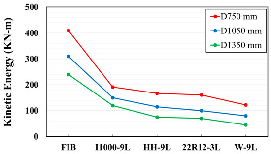
Figure 24.
Kinetic energies—all column diameters and selected retrofit schemes.
Higher residual axial capacities were again achieved with the W-9L configuration, which provided superior confinement and shear resistance compared to the other retrofitting schemes (Figure 25). Although the 12R22–3L columns exhibited significant surface cracking and concrete spalling, their residual capacities were comparable to those of the HH-9L and I1000-9L configurations. This performance was primarily due to the contribution of the longitudinal CFRP reinforcement in the 12R22–3L scheme, which effectively enhanced axial load-carrying capacity. These results suggest that while increasing longitudinal reinforcement can partially compensate for surface damage in terms of axial strength, repair strategies emphasizing full or targeted confinement, such as W-9L or HH-9L, may offer a more balanced approach by improving both strength retention and long-term durability.
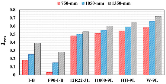
Figure 25.
Residual axial load-carrying capacity—all column diameters and selected retrofit schemes.
4. Summary and Conclusions
This study evaluated the effectiveness of two in-situ CFRP-based retrofitting strategies for restoring the structural performance of fire-damaged reinforced concrete (RC) bridge pier columns subjected to combined vehicle collision and air blast loading. The investigation was carried out using high-fidelity finite element simulations in LS-DYNA. The first retrofitting approach involved wrapping 750 mm diameter columns with externally bonded CFRP sheets, while the second employed a hybrid method that combined CFRP wrapping with near-surface mounted (NSM) longitudinal CFRP bars. Parametric studies were conducted to explore variations in CFRP wrap thickness and reinforcement ratios, alongside investigations of partial and intermittent wrapping configurations. The assessment was extended to include larger column diameters (1050 mm and 1350 mm) to further evaluate the effectiveness of the selected repair techniques. Using both CFRP wrap and hybrid techniques to repair fire-damaged columns considerably mitigate damage resulting from vehicle collisions and the subsequent air blasts. Key findings from simulation results are:
- Both CFRP wrapping and hybrid retrofitting strategies significantly improved the performance of fire-damaged columns, reducing damage from impact and blast demands.
- Retrofitting effectiveness varied depending on parameters such as CFRP wrap thickness and reinforcement ratio.
- Column response in the first scheme was highly sensitive to wrap thickness. Substantial performance gains were observed up to 1.5 mm thickness (W-9L), beyond which further increases provided negligible additional benefit. As such, W-9L was identified as the optimal configuration.
- Except for W-3L, all CFRP-wrapped columns in the first scheme maintained sufficient integrity to remain in service with minor repairs.
- For the hybrid scheme, noticeable performance improvements were primarily driven by increased CFRP wrap thickness rather than reinforcement ratio. Reinforcement contributed to stiffness and energy absorption but had a limited impact on crack and spalling mitigation.
- Increased CFRP reinforcement ratios for a given wrap thickness resulted in enhanced lateral stiffness, contributing to greater reductions in displacement and kinetic energy.
- The 4R12–1L and 4R12–3L configurations exhibited extensive damage and would require significant repairs, whereas other hybrid cases could remain serviceable with moderate rehabilitation.
- Partial wrapping strategies, particularly HH-9L and I1000-9L, proved effective in reducing displacement, kinetic energy, and spalling, outperforming bare and fire-damaged columns. In contrast, the I500-9L scheme demonstrated limited effectiveness due to higher levels of damage and displacement.
- Similar to W-9L, both HH-9L and I1000-9L preserved column functionality with minimal repair needs, while I500-9L would necessitate extensive rehabilitation to restore serviceability.
While the 750 mm-diameter columns served as the primary focus due to their heightened vulnerability to extreme events, larger columns (1050 mm and 1350 mm) were analyzed to assess the scalability of the proposed retrofitting methods. The reduced effectiveness of CFRP wraps in these larger columns, particularly regarding energy absorption, is attributed to scale effects. Larger-diameter columns exhibit lower slenderness ratios, which result in increased inherent stiffness and reduced lateral displacements, thereby limiting the benefit of CFRP confinement under dynamic loads. Additionally, higher axial load demands in larger sections diminish the relative improvement in residual capacity achieved through retrofitting. These observations suggest that CFRP retrofit strategies may require adaptation, such as increased reinforcement ratios or hybrid schemes, to maintain effectiveness across varying column sizes. While the proposed methods demonstrated reliable performance, future work should focus on size-dependent optimization to support broader repair technique adoption and field implementation.
Based on the observed response of fire-damaged columns and the imposed multi-hazard demands, the following recommendations are proposed for selecting retrofit strategies:
- Minimum Wrap Thickness: A CFRP wrap thickness of at least 1.5 mm is recommended to sufficiently restore structural capacity and avoid major post-event repairs.
- Reinforcement Ratio for Energy Demands: To minimize lateral displacements and kinetic energy, a CFRP reinforcement ratio of approximately 1%, combined with a minimum 0.5 mm wrap, is advised.
- Partial Wrapping Strategy: Wrapping the bottom half of the column height can provide effective protection against impact and blast while reducing material use.
- Intermittent Wrapping Guidance: For intermittent wrap configurations, ensuring that at least the lower 20% of the column height is covered is critical, as this region experiences the highest localized demands during impact.
In addition to these recommendations, it is important to note that while CFRP retrofitting strategies are not yet comprehensively addressed in current design codes such as AASHTO or Eurocode, their practical advantages, such as corrosion resistance, ease of application in constrained environments, and reduced labor demands, make them attractive alternatives to conventional methods like steel or concrete jacketing. The proposed strategies, particularly partial and intermittent wrapping, also improve constructability and offer cost-effective solutions that are well-suited for field implementation in multi-hazard-prone regions.
To further validate the proposed retrofitting schemes, full-scale or reduced-scale experimental testing is recommended. Additional research should also explore alternative retrofitting techniques, develop advanced modeling and assessment tools, and support the formulation of design guidelines and analytical provisions for fire-damaged bridge infrastructure subjected to multi-hazard loading.
Author Contributions
Conceptualization, Q.A.A. and D.G.L.; methodology, Q.A.A. and D.G.L.; software, Q.A.A.; validation, Q.A.A.; formal analysis, Q.A.A.; investigation, Q.A.A. and D.G.L.; resources, Q.A.A. and D.G.L.; data curation, Q.A.A.; writing—original draft preparation, Q.A.A.; writing—review and editing, Q.A.A. and D.G.L.; visualization, Q.A.A.; supervision, D.G.L.; funding acquisition, D.G.L. All authors have read and agreed to the published version of the manuscript.
Funding
The Mid-America Transportation Center funded this research through a grant from the US Department of Transportation’s University Transportation Centers Program (69A3551747107).
Institutional Review Board Statement
Not applicable.
Informed Consent Statement
Not applicable.
Data Availability Statement
Due to restrictions, the data presented in this study are available on request from the corresponding author. The data is not publicly available because this study is part of an ongoing large research project.
Acknowledgments
The authors would like to acknowledge the Mid-America Transportation Center for funding this research via a grant from the US Department of Transportation’s University Transportation Centers Program and the University of Nebraska’s Holland Computing Center for providing computational resources.
Conflicts of Interest
The authors declare no conflicts of interest.
References
- Woodworth, M.A. Fire Hazard Assessment for Highway Bridges with Thermal Mechanical Modeling. Ph.D. Thesis, Virginia Polytechnic Institute and State University, Blacksburg, VA, USA, 2013. [Google Scholar]
- Kodur, V.; Bhatt, B. Strategies for mitigating fire hazard in tunnel structures. In The 6th International Workshop on Structural Life Management of Power Structures; KEPCO-RI: Daejeon, Republic of Korea, 2016. [Google Scholar]
- Kodur, V.; Naser, M.Z. Fire hazard in transportation infrastructure: Review, assessment, and mitigation strategies. Front. Struct. Civ. Eng. 2021, 15, 46–60. [Google Scholar] [CrossRef]
- AASHTO LRFD. Bridge Design Specifications, 9th ed.; American Association of State Highway and Transportation Officials (AASHTO): Washington, DC, USA, 2020. [Google Scholar]
- National Fire Protection Association. NFPA 502: Standard for Road Tunnels, Bridges, and Other Limited Access Highways 2017; National Fire Protection Association (NFPA): Quincy, MA, USA, 2017. [Google Scholar]
- Michael, W.; William, W.; Brian, L. Fire risks for highway bridges: A statistical investigation. In Structures Congress 2013: Bridging Your Passion with Your Profession-Proceedings of the 2013 Structures Congress; ASCE: Pittsburgh, PA, USA, 2013; pp. 744–757. [Google Scholar]
- Peris-Sayol, G.; Paya-Zaforteza, I.; Balasch-Parisi, S.; Alós-Moya, J. Detailed analysis of the causes of bridge fires and their associated damage levels. J. Perform. Constr. Facil. 2017, 31, 04016108. [Google Scholar] [CrossRef]
- Garlock, M.; Paya-Zaforteza, I.; Kodur, V.; Gu, L. Fire hazard in bridges: Review, assessment and repair strategies. Eng. Struct. 2012, 35, 89–98. [Google Scholar] [CrossRef]
- Kodur, V.; Hibner, D.; Agrawal, A. Residual response of reinforced concrete columns exposed to design fires. Procedia Eng. 2017, 210, 574–581. [Google Scholar] [CrossRef]
- Guo, Z.; Chen, W.; Zhang, Y.; Zou, H. Post fire blast-resistances of RPC-FST columns using improved Grigorian model. Int. J. Impact Eng. 2017, 107, 80–95. [Google Scholar] [CrossRef]
- Chen, L.; Fang, Q.; Jiang, X.; Ruan, Z.; Hong, J. Combined effects of high temperature and high strain rate on normal weight concrete. Int. J. Impact Eng. 2015, 86, 40–56. [Google Scholar] [CrossRef]
- Bolina, F.L.; Gil, A.M.; Fernandes, B.; Hennemann, G.G.; Gonçalves, J.; Tutikian, B.F. Influence of design durability on concrete columns fire performance. J. Mater. Res. Technol. 2020, 9, 4968–4977. [Google Scholar] [CrossRef]
- Ruta, D. Numerical and Experimental Study of Concrete Structures Exposed to Impact and Fire. Ph.D. Dissertation, University of Stuttgart, Stuttgart, Germany, 2018. [Google Scholar]
- Chen, W.; Guo, Z.; Zhang, T.; Zou, H.; Gu, J. Near-field blast test on reactive powder concrete-filled steel tubular columns after exposure to fire. Int. J. Prot. Struct. 2016, 7, 193–212. [Google Scholar] [CrossRef]
- Jin, L.; Bai, J.; Zhang, R.; Li, L.; Du, X. Effect of elevated temperature on thelow-velocity impact performances of reinforced concrete slabs. Int. J. Impact Eng. 2021, 149, 103797. [Google Scholar] [CrossRef]
- Kakogiannis, D.; Pascualena, F.; Reymen, B.; Pyl, L.; Ndambi, J.M.; Segers, E.; Lecompte, D.; Vantomme, J.; Krauthammer, T. Blast performance of reinforced concrete hollow core slabs in combination with fire: Numerical and experimental assessment. Fire Saf. J. 2013, 57, 69–82. [Google Scholar] [CrossRef]
- Zhai, C.; Chen, L.; Xiang, H.; Fang, Q. Experimental and numerical investigation into RC beams subjected to blast after exposure to fire. Int. J. Impact Eng. 2016, 97, 29–45. [Google Scholar] [CrossRef]
- Fang, C.; Yosef, T.Y.; Linzell, D.G.; Rasmussen, J.D. Computational modeling and dynamic response of highway bridge columns subjected to combined vehicle collision and air blast. Eng. Fail. Anal. 2021, 125, 105389. [Google Scholar] [CrossRef]
- Tebor, C.; Sottile, Z. Section of Major I-95 Highway in Philadelphia that Collapsed After Tanker Truck Caught Fire Underneath Could Take Months to Repair, Officials Say; CNN: Atlanta, GE, USA, 2023. [Google Scholar]
- Hollaway, L.C.; Teng, J.-G. Strengthening and Rehabilitation of Civil Infrastructures Using Fibre-Reinforced Polymer (FRP) Composites; Elsevier: Amsterdam, The Netherlands, 2008. [Google Scholar]
- Bank, L.C. Composites for Construction: Structural Design with FRP Materials; John Wiley & Sons: Hoboken, NJ, USA, 2006. [Google Scholar]
- Alomari, Q.A.; Linzell, D.G. Reinforced Concrete Bridge Column Multi-Hazard Performance: A Computational Tool to Assess Response to Vehicle Impact, Air Blast, and Fire. J. Perform. Constr. Facil. 2023, 38. [Google Scholar] [CrossRef]
- Ashteyat, A.M.; Obaidat, Y.T.; Al-Btoush, A.Y.; Hanandeh, S. Experimental and numerical study of strengthening and repairing heat-damaged RC circular column using hybrid system of CFRP. Case Stud. Constr. Mater. 2021, 15, e00742. [Google Scholar]
- Chinthapalli, H.K.; Chellapandian, M.; Agarwal, A.; Prakash, S.S. Emergency Repair of Severely Damaged Reinforced Concrete Column Under Fire: An Experimental Study. In Proceedings of the 3rd ACF Symposium on Assessment and Intervention of Existing Structures, Sapporo, Japan, 10–11 September 2019; Volume 11. [Google Scholar]
- Anik, M.F.R.; Asif, M.M.H.; Raha, S.H.; Chowdhury, S.R. A comparison between strengthened CFRP and GFRP laminated RC beam: Finite element approach. J. Struct. Eng. Its Appl. Anal. 2020, 3, 1–16. [Google Scholar]
- ISO 834-1:2025; Fire Resistance Tests—Elements of Building Construction. International Organization for Standardization: Geneva, Switzerland, 2025.
- Hurley, M.J.; Gottuk, D.T.; Hall, J.R., Jr.; Harada, K.; Kuligowski, E.D.; Puchovsky, M.; Watts, J.M., Jr.; Wieczorek, C.J. SFPE Handbook of Fire Protection Engineering; Springer: New York, NY, USA, 2015. [Google Scholar]
- Hu, J.; Carvel, R.; Usmani, A. Bridge fires in the 21st century: A literature review. Fire Saf. J. 2021, 126, 103487. [Google Scholar] [CrossRef]
- Silva, P.F.; Hamdar, S.H.; Badie, S.S.; Chong, C.; Chiarito, V.P. Possible Methodology for Probabilistic Assessment of Bridge Safety Against Collisions and Fires; Department of Civil and Environmental Engineering, George Washington University: Washington, DC, USA, 2024. [Google Scholar]
- NYDOT. Bridge Fire Incidents in New York State; NYDOT: Albany, NY, USA, 2008. [Google Scholar]
- Kim, J.H.; Kim, C.K.; Islam, M.S.; Park, S.I.; Paik, J.K. A study on methods for fire load application with passive fire protection effects. Ocean. Eng. 2013, 70, 177–187. [Google Scholar] [CrossRef]
- Hallquist, J.O. LS-DYNA® Keyword User’s Manual: Volumes I, II, and III LSDYNA R7.1; Livermore Software Technology Corporation: Livermore (LSTC), CA, USA, 2014; Volume 1265. [Google Scholar]
- Yang, H.; Han, L.-H.; Wang, Y.-C. Effects of heating and loading histories on post-fire cooling behaviour of concrete-filled steel tubular columns. J. Constr. Steel Res. 2008, 64, 556–570. [Google Scholar] [CrossRef]
- 1992-1-1:2004; Eurocode 2: Design of Concrete Structures—Part 1-2: General Rules—Structural Fire Design. British Standard: London, UK, 2004.
- Alomari, Q.A. Structural Performance and Resiliency of Reinforced Concrete Bridge Pier Columns, Multi-Column Piers, and Bridge Systems Subjected to Multiple Hazards–Fire, Collision, and Air Blast. Ph.D. Thesis, The University of Nebraska-Lincoln, Lincoln, NE, USA, 2023. [Google Scholar]
- Mohan, P.; Marzougui, D.; Kan, C.D. Validation of a single unit truck model for roadside hardware impact. Int. J. Veh. Syst. Model. Test. 2007, 2, 1–15. [Google Scholar] [CrossRef]
- Williamson, E.B. Blast-Resistant Highway Bridges: Design and Detailing Guidelines; Transportation Research Board: Washington, DC, USA, 2010; Volume 645. [Google Scholar]
- Chipley, M. Reference Manual to Mitigate Potential Terrorist Attacks Against Buildings: Providing Protection to People and Building; Federal Emergency Management Agency: Washington, DC, USA, 2003. [Google Scholar]
- Day, J. Guidelines for ALE Modelling in LS-DYNA; Technical Report; Livermore Software Technology Corporation: Livermore, CA, USA, 2009. [Google Scholar]
- Wassef, W.G.; Smith, C.; Clancy, C.M.; Smith, M.J. Comprehensive Design Example for Prestressed Concrete (PSC) Girder Superstructure Bridge with Commentary (in SI Units); Federal Highway Administration: Washington, DC, USA, 2003. [Google Scholar]
- Reid, J.D.; Coon, B.A.; Lewis, B.A.; Sutherland, S.H.; Murray, Y.D. Evaluation of LS-DYNA Soil Material Model 147; Federal Highway Administration: Washington, DC, USA, 2004. [Google Scholar]
- Murray, Y.D. Users Manual for LS-DYNA Concrete Material Model 159; U.S. Department of Transportation: Washington, DC, USA, 2007. [Google Scholar]
- Reese, L.; Qiu, T.; Linzell, D.; O’Hare, E.; Rado, Z. Field tests and numerical modeling of vehicle impacts on a boulder embedded in compacted fill. Int. J. Prot. Struct. 2014, 5, 435–451. [Google Scholar] [CrossRef]
- Koneshwaran, S.; Thambiratnam, D.P.; Gallage, C. Blast response of segmented bored tunnel using coupled SPH–FE method. Structures 2015, 2, 58–71. [Google Scholar] [CrossRef]
- Murray, Y.D. Theory and Evaluation of Concrete Material Model 159; NASA: Washington, DC, USA, 2004. [Google Scholar]
- Sharma, H.; Hurlebaus, S.; Gardoni, P. Performance-based response evaluation of reinforced concrete columns subject to vehicle impact. Int. J. Impact Eng. 2012, 43, 52–62. [Google Scholar] [CrossRef]
- Linzell, D.G.; Fang, C.; Alomari, Q.A. Protecting Critical Civil Infrastructure Against Impact from Commercial Vehicles—Phase II; Mid-America Transportation Center, UNL: Lincoln, NE, USA, 2020. [Google Scholar]
- O’Hare, E.V. Computational Assessment of Steel-Jacketed Bridge Pier Column Performance Under Blast Loads. Master’s Thesis, The Pennsylvania State University, University Park, PA, USA, 2011. [Google Scholar]
- Lewis, B.A. Manual for LS-DYNA Soil Material Model 147; Federal Highway Administration: Washington, DC, USA, 2004. [Google Scholar]
- Alomari, Q.; Linzell, D.G.; Fang, C. Performance investigation of highway bridge pier columns under the sequential effects of fire followed by vehicle collision and subsequent air blast: A numerical investigation. Adv. Struct. Eng. 2024, 27, 1089–1114. [Google Scholar] [CrossRef]
- Alomari, Q.A.; Linzell, D.G. Advanced analysis of intact, fire-damaged, and CFRP retrofitted bridge pier columns under vehicle collisions: Empirical equivalent static force equation and framework. Eng. Struct. 2024, 314, 118250. [Google Scholar] [CrossRef]
- Fang, C.; Alomari, Q.A.; Linzell, D.G. Assessment of Bridge Pier Response to Fire, Vehicle Impact, and Air Blast. In Proceedings of the International Conference on Protective Structures (ICPS 2023), Auburn, AL, USA, 14–17 May 2023. [Google Scholar]
- Alomari, Q.A.; Linzell, D.G.; Abu Zouriq, M.F. Response of Bare and CFRP-Retrofitted Multi-Column Piers Under Post-Fire-Coupled Vehicle Collision and Air Blast. Materials 2025, 18, 1449. [Google Scholar] [CrossRef]
- Williams, G.D. Analysis and Response Mechanisms of Blast-Loaded Reinforced Concrete Columns. Ph.D. Thesis, University of Texas at Austin, Austin, TX, USA, 2009. [Google Scholar]
- Liu, L.; Feng, H.; Tang, H.; Guan, Z. Impact resistance of Nomex honeycomb sandwich structures with thin fibre reinforced polymer facesheets. J. Sandw. Struct. Mater. 2018, 20, 531–552. [Google Scholar] [CrossRef]
- Deleo, F.R.; Feraboli, P. Crashworthiness Energy Absorption of Carbon Fiber Composites: Experiment and Simulation. Ph.D. Thesis, University of Washington, Seattle, WA, USA, 2011. [Google Scholar]
- Fang, C.; Linzell, D.G.; Yosef, T.Y.; Rasmussen, J.D. Numerical Modeling and Performance Assessment of Bridge Column Strengthened by FRP and Polyurea under Combined Collision and Blast Loading. J. Compos. Constr. 2022, 26, 04022002. [Google Scholar] [CrossRef]
- Mutalib, A.A.; Hao, H. Numerical analysis of FRP-composite-strengthened RC panels with anchorages against blast loads. J. Perform. Constr. Facil. 2011, 25, 360–372. [Google Scholar] [CrossRef]
- Nam, J.-W.; Kim, H.-J.; Kim, S.-B.; Yi, N.-H.; Kim, J.-H.J. Numerical evaluation of the retrofit effectiveness for GFRP retrofitted concrete slab subjected to blast pressure. Compos. Struct. 2010, 92, 1212–1222. [Google Scholar] [CrossRef]
- Wang, W.; Wu, C.; Li, J. Numerical simulation of hybrid FRP-concrete-steel double-skin tubular columns under close-range blast loading. J. Compos. Constr. 2018, 22, 04018036. [Google Scholar] [CrossRef]
- Sami, A. 3. Effectiveness of External CFRP Wrapping on the Structural Behavior of Damaged FRP-RC Spiral Columns. In Proceedings of the 1st International Conference on Recent Advances in Civil and Earthquake Engineering (ICCEE-2021), Peshawar, Pakistan, 8 October 2021; p. 8. [Google Scholar]
- Kimura, H.; Itabashi, M.; Kawata, K. Mechanical characterization of unidirectional CFRP thin strip and CFRP cables under quasi-static and dynamic tension. Adv. Compos. Mater. 2001, 10, 177–187. [Google Scholar] [CrossRef]
- Sayed-Ahmed, E.Y. Numerical investigation into strengthening steel I-section beams using CFRP strips. In Structures Congress 2006: Structural Engineering and Public Safety; ASCE: St. Louis, MO, USA, 2006; pp. 1–8. [Google Scholar]
- Sha, Y.; Hao, H. Laboratory tests and numerical simulations of CFRP strengthened RC pier subjected to barge impact load. Int. J. Struct. Stab. Dyn. 2015, 15, 1450037. [Google Scholar] [CrossRef]
- Razaqpur, A.G.; Tolba, A.; Contestabile, E. Blast loading response of reinforced concrete panels reinforced with externally bonded GFRP laminates. Compos. Part B Eng. 2007, 38, 535–546. [Google Scholar] [CrossRef]
- Sudeep, K.; Rao, V.N. Structures to Resist the Effects of the Accidental Explosions. Int. J. Trend Sci. Res. Dev. 2019, 3, 1528–1530. [Google Scholar] [CrossRef]
- ACI 440.1R-15; Guide for the Design and Construction of Structural Concrete Reinforced with FRP Bars. ACI: Farmington Hills, MI, USA, 2015.
- ACI 440.2R-17; Guide for the Design and Construction of Externally Bonded FRP Systems for Strengthening Concrete Structures. ACI: Farmington Hills, MI, USA, 2017.
- Al-Nimry, H.S.; Ghanem, A.M. FRP confinement of heat-damaged circular RC columns. Int. J. Concr. Struct. Mater. 2017, 11, 115–133. [Google Scholar] [CrossRef]
- Chinthapalli, H.K.; Chellapandian, M.; Agarwal, A.; Prakash, S.S. Effectiveness of hybrid fibre-reinforced polymer retrofitting on behaviour of fire damaged RC columns under axial compression. Eng. Struct. 2020, 211, 110458. [Google Scholar] [CrossRef]
- Choo, C.C.; Harik, I.E.; Gesund, H. Minimum reinforcement ratio for fiber-reinforced polymer reinforced concrete rectangular columns. ACI Struct. J. 2006, 103, 460. [Google Scholar]
- Al-Nimry, H.; Haddad, R.; Afram, S.; Abdel-Halim, M. Effectiveness of advanced composites in repairing heat-damaged RC columns. Mater. Struct. 2013, 46, 1843–1860. [Google Scholar] [CrossRef]
- Fang, C. Structural Resilience and Hardening of Bridge Piers and Pier Columns Against Vehicle Collision and Blast Loads; The University of Nebraska—Lincoln: Lincoln, NE, USA, 2020. [Google Scholar]


Disclaimer/Publisher’s Note: The statements, opinions and data contained in all publications are solely those of the individual author(s) and contributor(s) and not of MDPI and/or the editor(s). MDPI and/or the editor(s) disclaim responsibility for any injury to people or property resulting from any ideas, methods, instructions or products referred to in the content. |
© 2025 by the authors. Licensee MDPI, Basel, Switzerland. This article is an open access article distributed under the terms and conditions of the Creative Commons Attribution (CC BY) license (https://creativecommons.org/licenses/by/4.0/).