Abstract
This study focuses on developing an experimental setup to investigate the Selective Melt Dispersion (SMD), a Directed Energy Deposition (DED) process. SMD as a means of in-process joining (IPJ) aims to integrate components and assemblies during additive manufacturing, combining the advantages of various processes for eco-friendly and economical resource utilization. The research initially analyzed DED systems and defined requirements for subsystems and the overall system. Critical subsystems, including the energy source, material feed, and others, were sequentially developed, and a proof of concept involved building 20 stacked welded tracks, validated through micrograph analysis. The study concludes by evaluating and discussing the fulfillment of the defined requirements. The system comprises a centrally arranged vibration-assisted powder feed; a laterally arranged laser incidence at a 45° angle; a kinematic structure where all axes are arranged on the workpiece, so the powder supply does not require movement; and a shield gas supply.
1. Motivation
Currently, additive manufacturing processes are mainly used to manufacture components, which then have to be finished conventionally, often on all faces. These components are then conventionally joined to other components to form assemblies which can be utilized. In general, additive processes take place almost exclusively at the beginning of the process chain. An integration into conventional process chains has rarely taken place up to now. To integrate additive processes into integrated process chains, however, it is necessary to additively join and expand various prefabricated components. Here, additive processes are used to combine the various advantages of the respective manufacturing processes in one structure or hybrid product and to compensate for the disadvantages of the processes. Various approaches, such as repairing turbine blades using Directed Energy Deposition (DED) [1], adding stiffening structures through DED to conventionally manufactured components [2,3], or employing hybrid processes like Powder Bed Fusion (PBF) combined with CNC milling on a single machine [4,5], follow similar methodologies. However, these approaches are frequently tailored to specific components or applications and may not be universally applicable. Dahlmeyer et al. [6] have identified the need for new additive processes to realize a general approach for the integration of additive technologies into integrated conventional process chains and have theoretically described a novel process—Selective Melt Dispersion (SMD). SMD is a DED process and differs from the state of the art in terms of its technical equipment, namely, a vibration-assisted powder feed [7,8]. It is assumed that the gentle introduction of powder into the melt pool, in contrast to gas-flow-conveyed powder, has advantages with regard to the resulting surface finish [9,10]. Sufficient surface quality is currently achieved by machining [11].
Additive manufacturing offers environmental advantages over conventional methods due to reduced waste generation and increased energy efficiency. Traditional manufacturing often results in higher material waste through subtractive processes, while additive manufacturing minimizes waste by building components layer by layer using only the necessary amount of material. Additionally, additive manufacturing enables the production of lightweight structures with optimized designs, reducing material usage and energy consumption, especially for complex geometries. Studies have shown that additive manufacturing processes can potentially reduce CO2 emissions by up to 40% compared to traditional methods, primarily due to decreased waste and increased energy efficiency. However, the environmental impact of additive manufacturing depends on factors such as the technology, production scale, and materials used. Despite its benefits, certain metal 3D printing techniques may still have significant energy consumption, requiring consideration of the overall environmental impact.
The SMD process can be used to create components that do not require any (subtractive) post-processing from a technical point of view. This in turn preserves resources and thus reduces the ecological footprint of components and assemblies. This paper introduces an initial experimental setup designed to demonstrate the feasibility of the SMD process in principle. The current configuration is not a finalized productive system; instead, its purpose is to facilitate the analysis of the process and the development of a process model. The SMD process model serves as the basis for implementing in-process joining (IPJ).
2. Methodology
First, DED systems are analyzed in general and then divided into subsystems to facilitate individual development. Requirements for the system technology are then derived from the underlying strategy [6], which should also fulfil two different objectives. Firstly, the system should enable the validation of the actual technical implementation and, secondly, the system should enable the creation of a process model for SMD. The subsystems are then developed, taking the derived requirements into account. The technical data are presented for the merged and combined subsystems. An initial experiment was carried out for proof of concept. It is then analyzed whether and to what extent the requirements are met.
3. Requirements for System Technology
For easier experimental realization, it is advisable to divide the SMD system into subsystems. This distinction enables a targeted evaluation of the subsystems, which can subsequently be combined into an overall system, taking into account possible interactions. An analysis of existing DED systems resulted in the following subsystems:
| • Energy source and supply • Material feed • Shield gas supply • Kinematics | • Camera system • Control system • (Enclosure) • (Suction) |
For further abstraction and simplification, the following subsystems are excluded from the initial analysis: The subsystem enclosure is not considered in detail for the moment, as a sufficient enclosure already exists. The subsystem suction is also not considered in an initial setup, as it can be arranged in the vicinity of the process action point if the powder quantities are small and the process times are short, as in the initial trials.
The requirements for the subsystems’ energy source and supply, material supply, shield gas supply, and kinematics of the experimental setup are described below. The experimental setup serves a dual purpose:
- (1)
- To validate the actual technical implementation of the SMD process, which has not been theoretically conceptualized until now.
- (2)
- To facilitate the planned investigation of the SMD process for the creation of a process model.
The requirements according to (1) concentrate on the basic structure and the linking of the subsystems, whereas the requirements from (2) primarily focus on the practicability and the variation of process parameters. Additionally, the expansion stage of the experimental setup, in which the respective requirements need to be implemented, is identified. The first expansion stage emphasizes the fundamental testing of the process, while the second expansion stage aims to enable the processing of actual components. Currently, the emphasis is on implementing expansion stage 1.
4. Development of the Subsystems
In the subsequent subsections focusing on individual subsystems, this paper lists and assesses solutions outlined in the literature and applied in industrial settings for Directed Energy Deposition (DED) subsystems. The evaluation considers their applicability in the Selective Laser Melting (SMD) process or the first expansion stage of the experimental setup. Utilizing the previously outlined requirements (refer to Table 1) and other valid exclusion criteria, the implementation details for each respective subsystem are elaborated below.

Table 1.
Requirements for the experimental setup (implementing and analyzing the SMD process).
4.1. Material Feed
In powder feeding, both the geometric arrangement in the overall system and the physical principle for feeding the powder are considered. With regard to the geometric arrangement, a distinction is made between lateral, central, discrete coaxial, and continuous coaxial systems [2]. State-of-the-art DED systems with lasers and powder use a continuous coaxial powder feed. In this process, powder is supplied into the welding pool continuously from all directions through a nozzle featuring a circular outlet positioned coaxially around the energy source. Discrete coaxial systems enable powder to be deposited from more than two discrete directions into the melt pool. However, due to the discrete nozzles, there is an inhomogeneous distribution of the powder depending on the position. Individual powder feed nozzles are either arranged off-axis, with a distinct angle to the focus of the energy source (lateral powder feed nozzle), or positioned centrally (annular powder feed nozzle). For central positioning, the energy source must be designed laterally (off-axis) or coaxially (annular). Both systems are sufficient for initial straight-line experiments. Lateral powder feed nozzles can be upgraded to a system that enables unidirectional processes by adding a movable powder feed. For the first expansion stage of the experimental setup, a centralized powder feed was chosen because the relative positioning between the energy and powder feed can be adjusted more easily and precisely via beam-guiding mirrors than by adjusting the mechanical mounting of the powder feed.
With regard to the physical principle of powder feeding, gravity-assisted, vibration-assisted, and gas-assisted powder feeders are known. State-of-the-art powder feeders are gas-assisted, which convey powder through pipes, lines, and the nozzle to the process action point by means of a protective gas flow. However, this cannot be used for the SMD process, as the parameters for controlling the shield gas supply and those for adjusting the powder supply are coercively interlinked. In addition, the gas velocity is transmitted to the powder. This can lead to the partially melted or fused powder bouncing off and sticking in unwanted places, which has a negative effect on the surface quality [9]. Pure gravity conveying cannot be used, as the small particle diameters of non-flowable and poorly flowable powder qualities can clog hoses, pipes, and nozzle outlets. Vibration-assisted powder feeding [12] can clear these blockages by applying a vibration to the system and thus the powder. The flowable particles are then accelerated by gravity. In addition, this type of powder feed is not linked to the parameters controlling other subsystems.
The vibration-assisted powder feed (VAPF) basically consists of a continuous tube, which is tapered in the vicinity of the powder deposit or at the nozzle of the VAPF. Depending on their morphology, the particle diameter distribution, the nozzle diameter, and the roughness of the inner wall of the nozzle, non-flowable and poorly flowable powder grades tend to have a so-called bridging effect. In the nozzle, the individual particles wedge, in a mechanically similar way to the bricks of an ancient archway. The nozzle wall serves as a kind of support for the “bridge”. However, in a vibrating system, these “particle bridges” can be “broken”, resulting in a gravity-assisted powder flow through the VAPF. When the vibration ends, bridges form again, thus blocking the powder flow. As there was no previous experience with VAPFs or powder handling itself, this subsystem was categorized as critical compared to the other subsystems. Based on the assessment described, the VAPF was the first subsystem to be developed and tested (Figure 1).
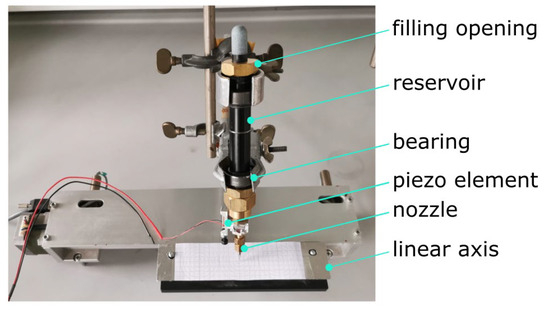
Figure 1.
Testing the vibration-assisted powder feed system.
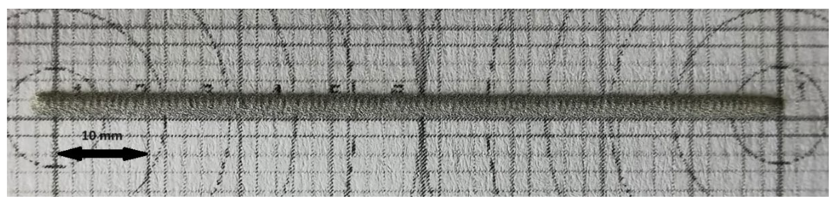
The structure of the VAPF consists of a tube that stores powder and is mounted on damping elements. The filler neck where the powder is introduced is located at the upper end of the tube. In the lower section, a piezo element is located close to the nozzle, which can be triggered to vibrate via alternating voltage. When this voltage is applied, powder flows out of the nozzle tip during transitions. Figure 2 shows an example of a powder trail deposited on graph paper.
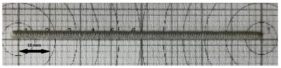
Figure 2.
Example of a powder track deposited using the vibration-assisted powder feed.
4.2. Energy Source and Supply
In DED processes, an electric arc, laser beam, electron beam, or the principle of cold gas spraying is used as the energy source [13]. With an electric arc, focusing the arc is difficult compared to the other energy sources mentioned, as the arc expands between the energy source and the process action point. As energy has to be introduced locally as defined in the SMD process, the arc is ruled out. Lasers can be focused using optical lenses and the beam can easily be guided using mirrors. When using an electron beam for metal processing, a vacuum is established along the trajectory of the electrons to prevent deflection of the electrons and chemical reactions between the molten metal and the ambient air. In addition, beam guidance and focusing is more complicated than using a laser beam because magnetic fields have to be installed to guide the beam. Due to the complex and currently non-available system technology at HTW Berlin, the electron beam is also excluded from consideration. In cold gas spraying, powder particles are shot onto the substrate in a gas stream at supersonic speed [14]. The system and safety technology required is very complex. In addition, there is no experience with such systems up to now.
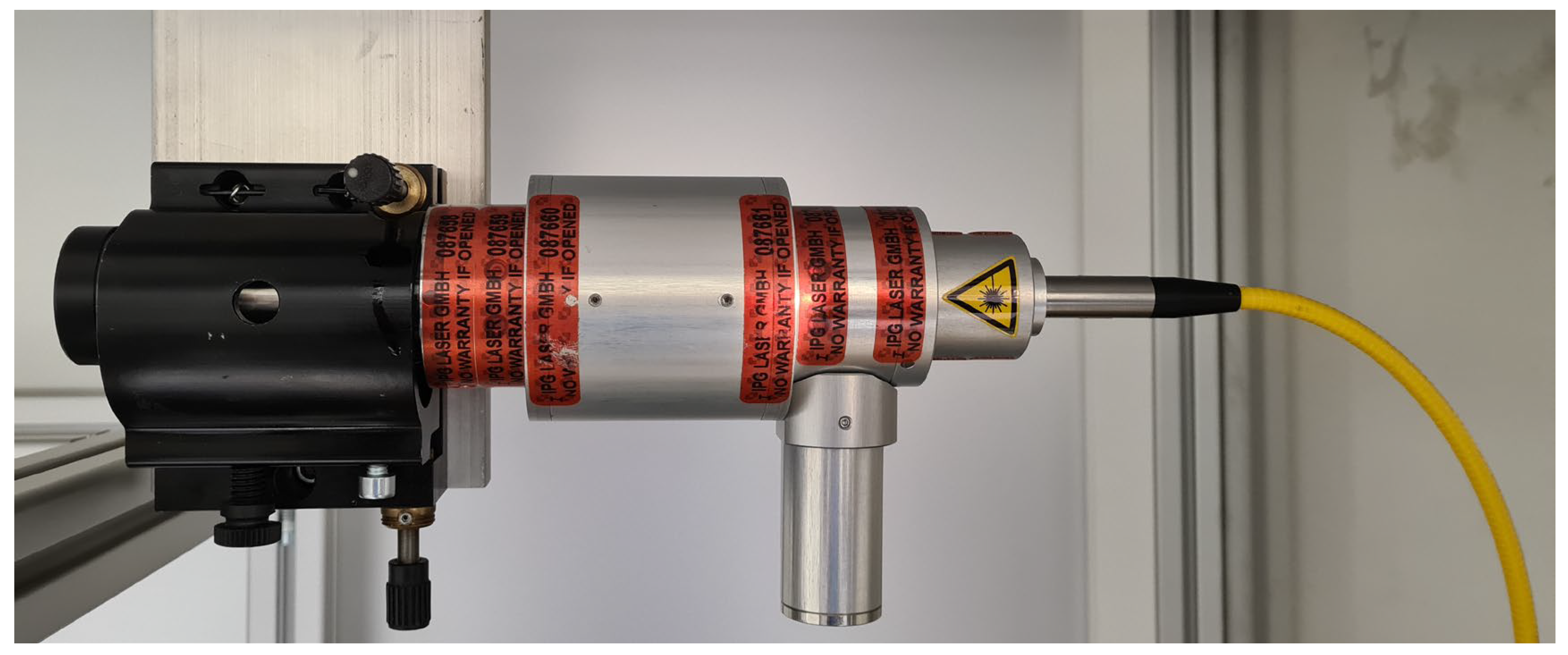
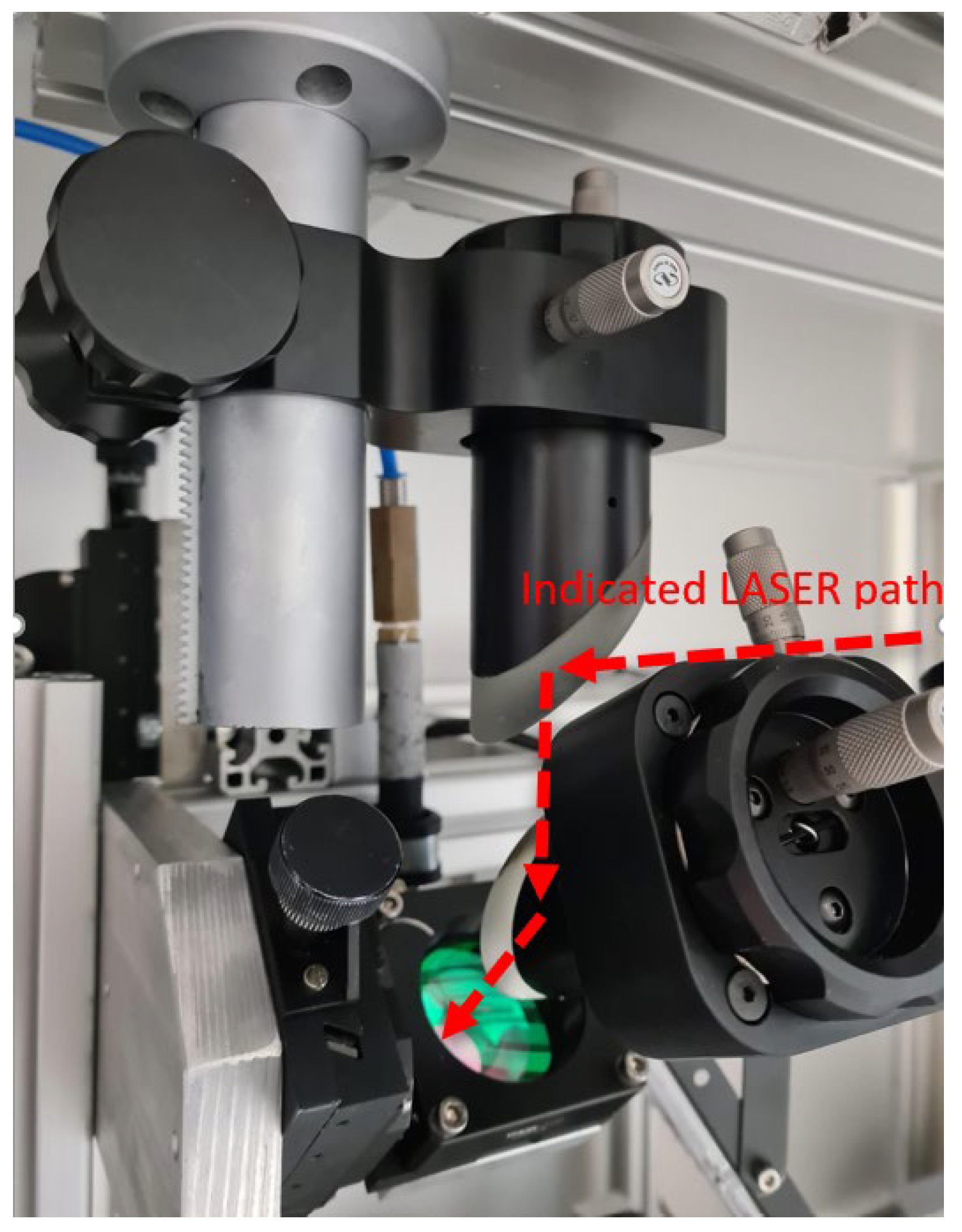
An IPG YLP-HP-10-400-20-200 laser was used as the energy source as it is both suitable to meet the requirements and available. The laser beam is guided from the actual laser or rather the laser-active medium via an optical fiber to the optical isolator (Figure 3). Starting from the optical isolator, the horizontally traveling cumulative laser beam is deflected vertically downwards via a 90° mirror. From here, the beam is deflected via a second mirror at a 45° angle in the direction of the process action point (Figure 4). Before the beam reaches the process action point, it is focused to a spot diameter of 0.3 mm using a lens (focal length: 200 mm).
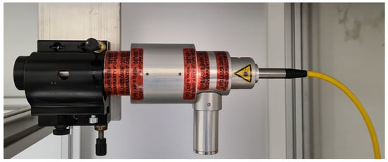
Figure 3.
Optical isolator with fiber-optic cable (yellow) and corresponding holder for adjusting the position and alignment.

Figure 4.
Tiltable and rotatable 90° mirror and height-adjustable focus lens.
4.3. Shield Gas Supply
To prevent chemical reactions between the melt and the ambient air, an inert shield gas should be used to displace the ambient air at the process action point. The quantities of gas used also increase the need for safety technology (risk of asphyxiation). In addition to the protective gas atmosphere, a gas flow must also be installed in the chamber so that vapors produced during the process can be removed from the process action point. By opting for the chosen method of localized shield gas supply, it is only necessary to position a single nozzle in close proximity to the process action point.
As the powder is mainly accelerated by gravity (additional acceleration effects can occur due to the applied vibration) and the particles have a low mass, a powder flow or trickling of the powder that is sensitive to interference is expected. In addition to the requirements in Table 1, this results in further requirements for a suitable shield gas supply:
- It must be possible to supply a sufficient quantity of shield gas to the process action point to displace the ambient air.
- The shield gas velocity must be sufficiently high to dissipate any vapors.
- The shield gas velocity must not negatively influence the trajectory of the trickling powder or deflect the trickling powder.
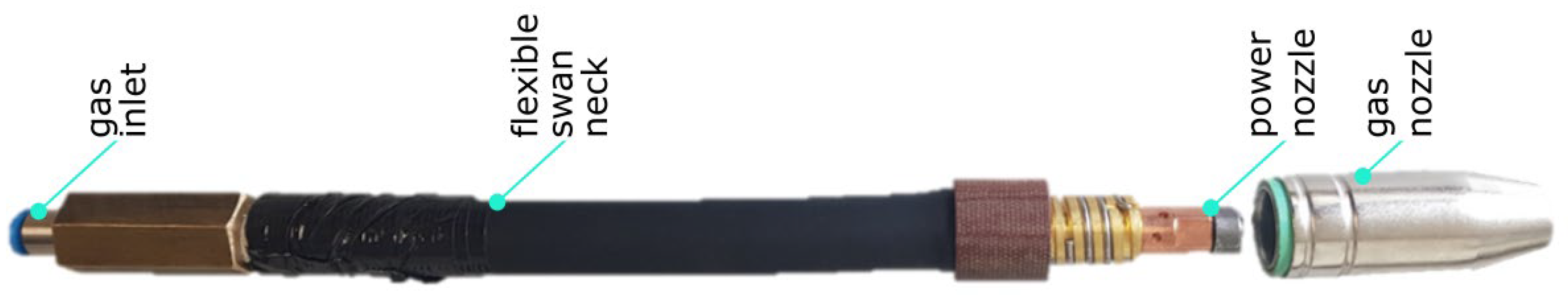
To ensure a laminar flow of the shield gas, the system applies the long-established principle and design of a welding torch (Figure 5). A flexible torch neck was selected in order to enable slight adjustment of the position in the assembled state. The contact tip in the front area of the shield gas supply was closed with a cylinder screw to avoid negative influence on the flow. An adapter for a plug connection, which in turn serves to hold the gas-conveying hose, was fitted to the rear part of the supply.
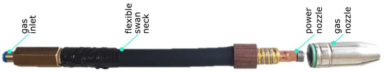
Figure 5.
Structure of the shield gas supply.
4.4. Kinematics
The kinematics used in DED processes are Cartesian kinematics with rotary and swiveling axes or serial kinematics such as articulated arm robots. Parallel kinematics in combination with rotary and swiveling axes are also available, but these are excluded from the experimental setup because controlling them is more complex compared to Cartesian systems. Serial kinematics are also more complex to control, and they are financially demanding if increased accuracy is required. Nevertheless, they enable almost all-round machining and are therefore envisaged as a solution for the second expansion stage. Cartesian kinematics with three axes were selected for the first expansion stage. These are favorable in economic terms. Moreover, there is experience with the control system, and Cartesian kinematics are sufficient for initial straight-line tests.
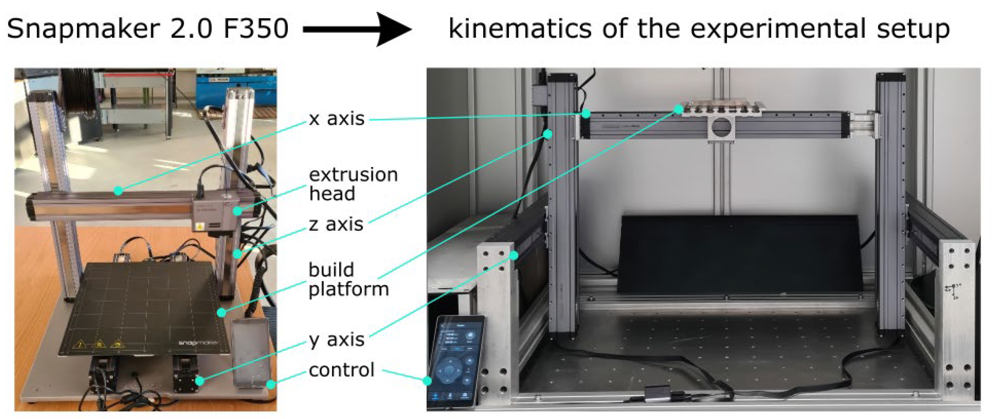
Due to the way the VAPF works, it reacts sensitively to vibrations. Powder therefore flows as soon as the VAPF is exposed to vibrations or shocks. As the kinematic structure allows all relative movements between the workpiece and the tool, it can be assumed that the movement of the axes leads to unwanted powder flow. This is particularly the case if the VAPF itself has to be moved. Therefore, all axes were arranged on the workpiece guaranteeing that the processing head remains immobile. Note, this axis arrangement is rarely used with Cartesian kinematics because, on the one hand, the load on the axes increases, and thus the payload is reduced. And, on the other hand, the possible machining area is smaller than for setups of the same size with a split axis arrangement.
As no kinematics could be realized with existing components, a suitable and economically favorable solution was found by adjusting the existing Snapmaker 2.0 F350 MEX (Snapmaker, Shenzhen, China) printer (Figure 6). The axes are operated in close proximity to the laser and metallic powder. Hence, the closed all-metal axes with integrated stepper motors and spindle drive are particularly advantageous.

Figure 6.
Snapmaker 2.0 F350 and converted Cartesian kinematics with all axes arranged on the workpiece.
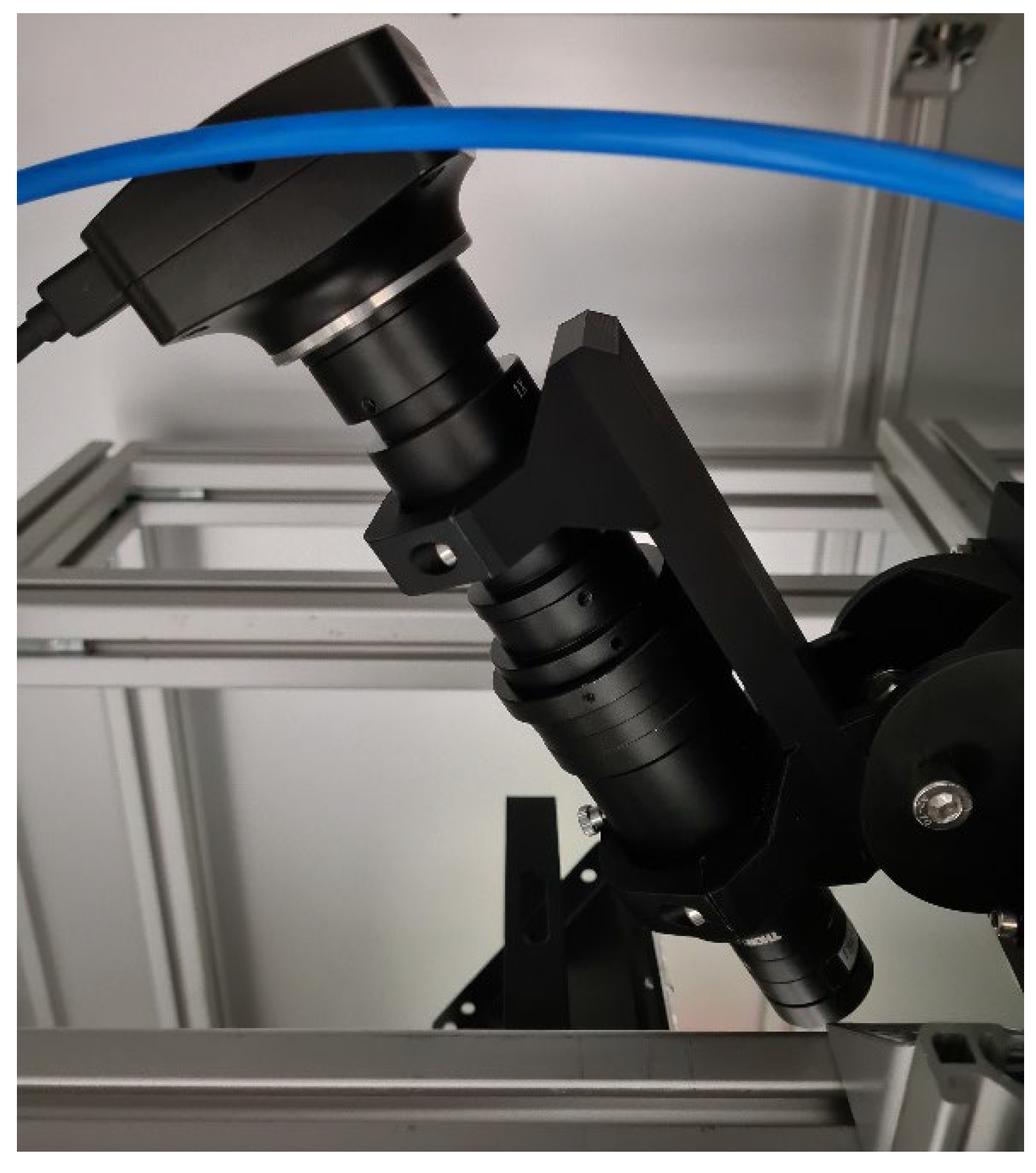
4.5. Camera System
A camera system was developed to visually analyze the process or the process action point (Figure 7). A Bresser MikroCam II microscope camera was combined with a magnifying lens and a Thorlabs FBH400-40 bandpass filter (Thorlabs, Inc., Newton, NJ, USA) (400 nm ± 20 nm). Among other wavelengths, the bandpass filter filters out the wavelengths of the laser and the blackbody radiation to prevent overexposure at the process site. Two UV lamps (395 nm) were used for illumination.
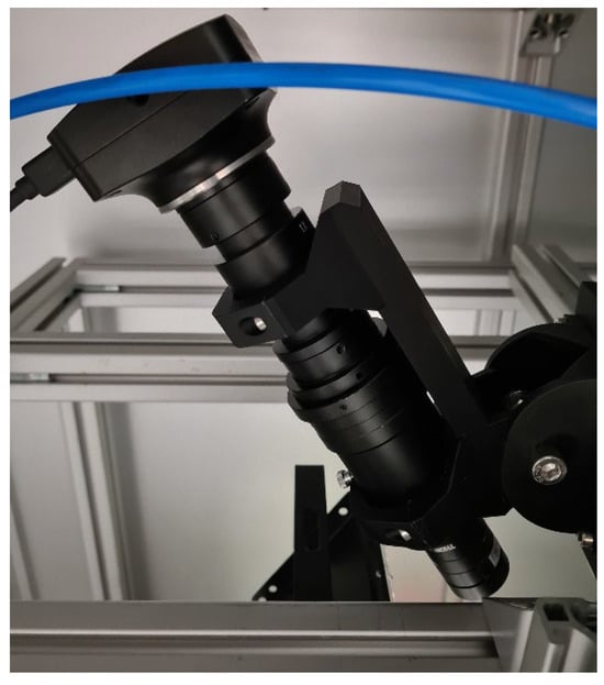
Figure 7.
Camera system for optical analysis of the process action point.
4.6. Control System
All subsystems are controlled using the freeware “Klipper”, which runs on a RaspberryPI 4b. The laser and the powder feeder are activated easily as only one IO output needs to be powered. The axes had to be modified so that a direct connection of the stepper motors to the custom power electronics was possible. The experimental setup can therefore be controlled using G Code. The major advantage of the centrally implemented control of all systems is the synchronized operation: the laser and powder can be switched on and off depending on the current position of the kinematics.
5. Merging of the Subsystems
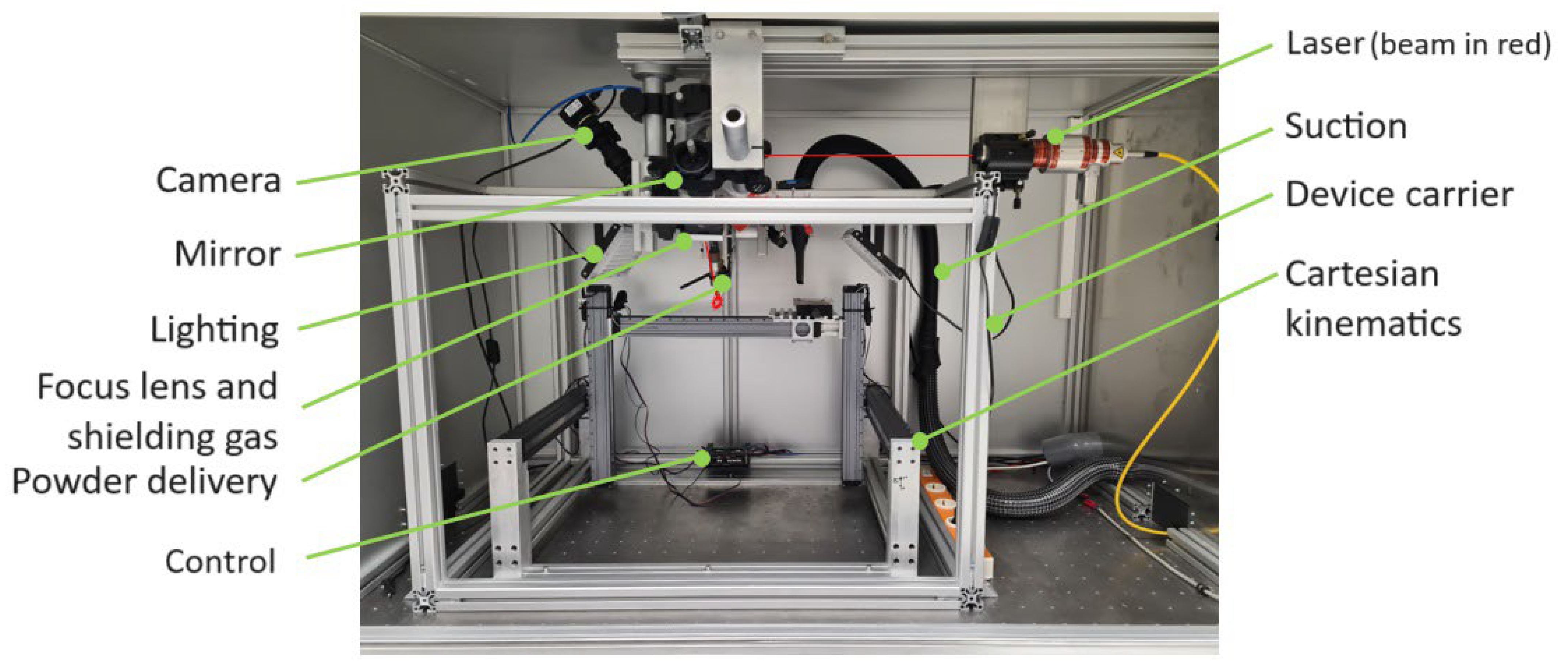
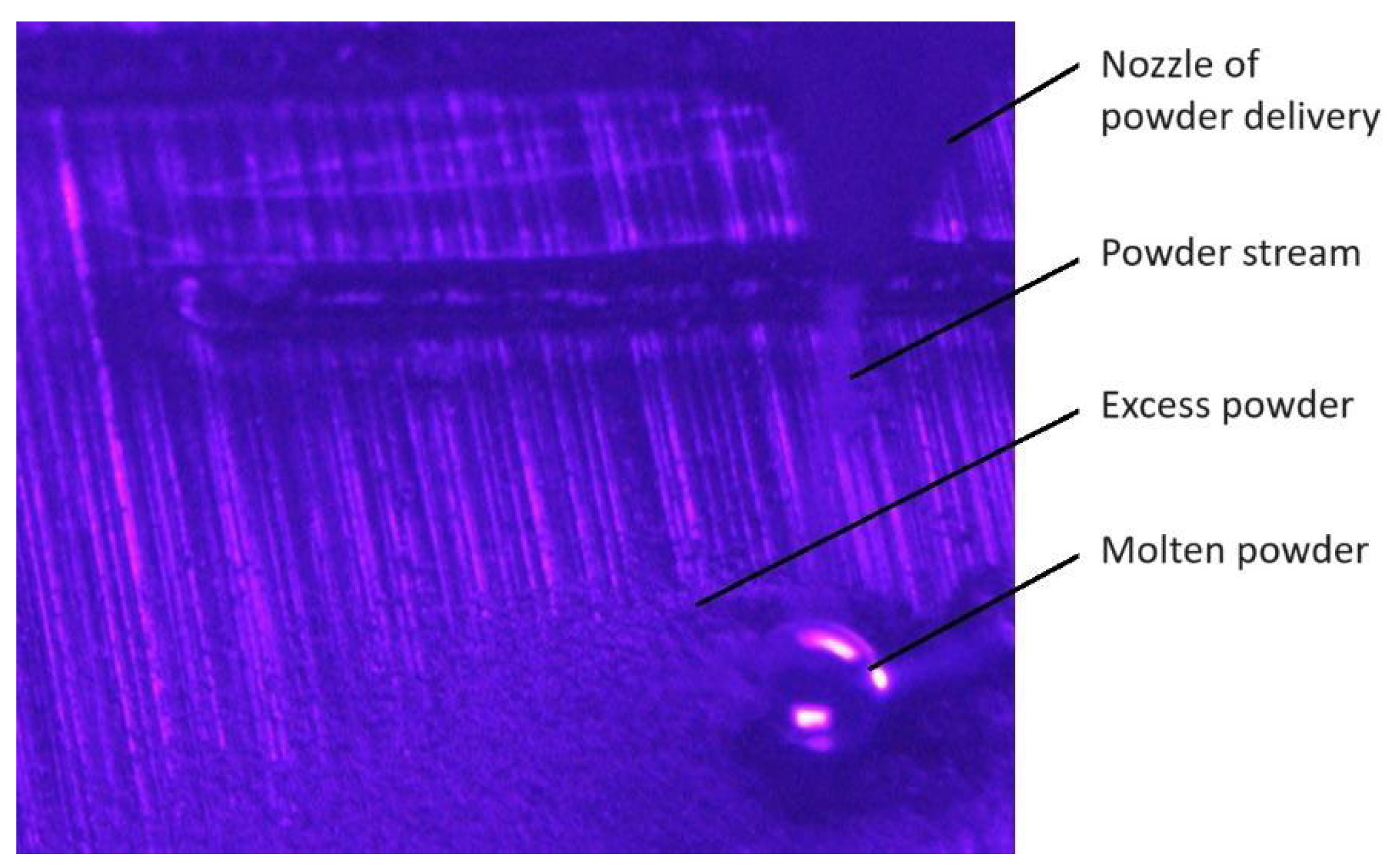
The individual subsystems were now merged to validate the potential of the SMD system for in-process joining technology. Firstly, the kinematics were mounted in a laser protection chamber. A rectangular frame made of aluminum profiles (Figure 8) was then built around the kinematics as an equipment carrier. The powder feed (Figure 9) and the shield gas feed (Figure 9) were each attached to this frame. A microscope camera was also attached for online observation of the process. The frame enables the vibration-sensitive powder feed and the kinematics or moving parts to be structurally separated. However, if vibrations caused by the other parts of the system lead to powder flow, future studies will be carried out to dampen the system. An aluminum profile was attached to the ceiling of the laser protection chamber to accommodate the optical isolator (Figure 3) of the laser and the two 90° mirrors (Figure 4) that deflect the laser beam towards the process action point. A focusing lens (Figure 4) was attached to the frame to focus the laser beam. A microscope camera with magnifying optics and a bandpass filter were installed for in situ observation of the process. The bandpass filter selectively permits the wavelength of UV light to pass through, rendering the melt pool visible (Figure 10). Table 2 summarizes the technical data of the experimental setup.

Figure 8.
Experimental setup of the 1st expansion stage (SMD).
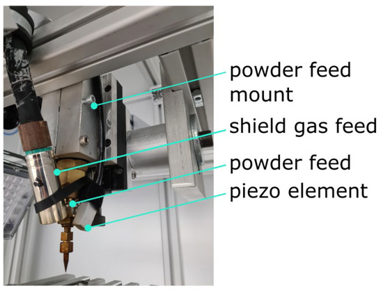
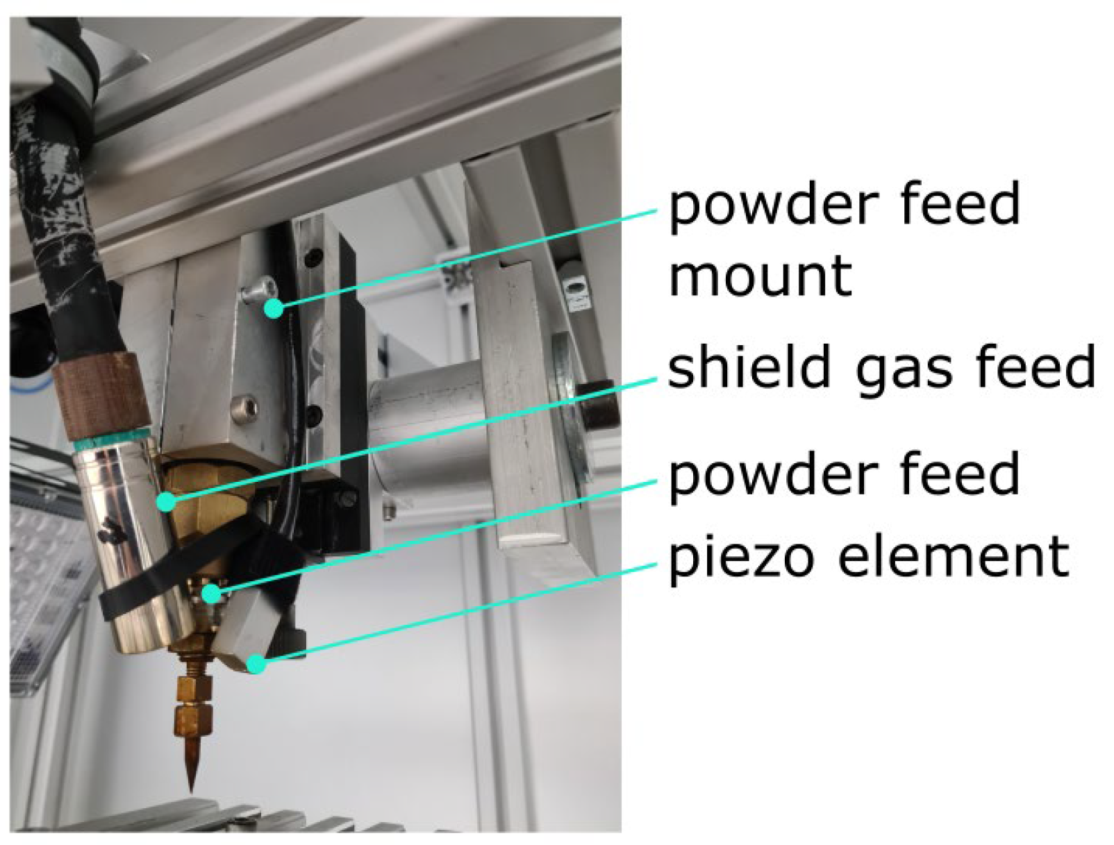
Figure 9.
Vibration-assisted powder feed with mount and shield gas feed.

Figure 10.
In situ image of the process taken with the camera system.
Table 2.
Technical data of the 1st expansion stage of the experimental setup.
6. Proof of Concept
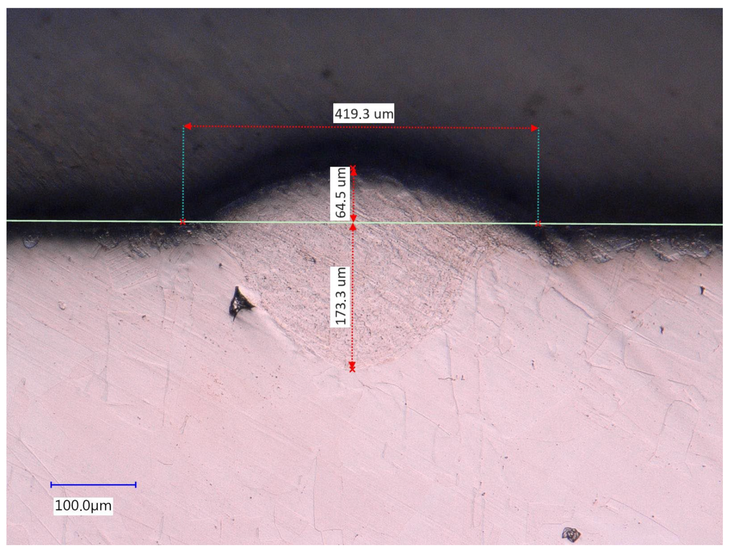
An initial series of tests was carried out as a proof of concept using austenitic stainless steel 316L. Process parameters that have proven to be effective in previous experiments were selected processing Oerlikon Metco 316L-A powder, (laser power P = 150 W; feed rate f = 50 mm/s; pulse repetition rate PPR = 50 kHz). Twenty welding tracks were placed on top of each other. Powder residue was removed between the tracks in order to prevent falsification of the material structure by any remaining powder. The laser and powder feed were focused onto the same spot.
The samples were then cut perpendicular to the welding direction, ground, polished, and treated with V2A stain at 70 °C. The micrographs were viewed and measured using a Keyence VHX 5000 microscope (Figure 11).
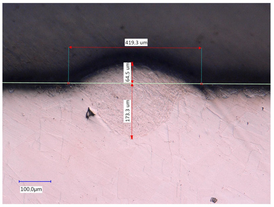
Figure 11.
Micrograph of 20 welded tracks placed on top of each other.
As a positive outcome, material build-up took place, demonstrating the general functionality of the experimental setup. The good material bonding and the absence of cracking proved that the process parameters were well selected.
7. Discussion
In addition to the proof of concept, which merely demonstrates the general functionality of the experimental setup as a DED system, the fulfillment of the requirements from Table 1 is now discussed. For this purpose, the most important requirements of Table 1 are summarized and evaluated in Table 3.
Table 3.
Evaluating the capabilities achieved by the experimental setup in comparison to the requirements for in-process joining realization.
Validation of the SMD process is possible using the newly introduced experimental setup. The control and synchronization of the subsystems are inevitable for future experiments. Future tests will show whether reproducible results can be achieved. In the second expansion stage, an articulated arm robot is planned to replace the Cartesian kinematics. This will then enable the actual in-process joining or imprinting of components, presupposing that the process window is defined.
A comparison of the existing setup with state-of-the-art DED systems demonstrates that the main difference is the type of powder feed [15]. Normally, the powder is conveyed to the process action point within a gas stream. In that case, however, the gas velocity is imposed on the powder, causing it to reach the melt pool at a high kinetic energy level. This presumably leads to comparatively poor surface finishes [9], which have to be reworked after the additive process. In the present setup, a vibration-assisted powder feed is used, which allows the powder to trickle towards the melt pool with low energy, presumably allowing for better as-built surface quality [8]. If component surfaces are sufficiently good, economically and ecologically demanding rework can be avoided. A disadvantage of the current approach is the comparatively low build-up rates. Gas-assisted powder feeders enable a significantly higher powder throughput than vibration-assisted powder feeders.
8. Conclusions
An additive process was theoretically designed that enables the joining of components to assemblies during the additive (assembly) process or in-process joining as a general approach. This approach includes the avoidance of (chipping) reworking after the additive process, whereby both economic and ecological resources can be saved, and thus the ecological footprint of components and assemblies is reduced.
For this purpose, the experimental setup was conceptually divided into distinct subsystems. The requirements were derived for each subsystem from the fundamental strategy and have been presented. Due to the complexity, the setup was divided into two expansion stages. The first intends to enable a general feasibility and validation of the SMD process. The second expansion stage overcomes the Cartesian space and thus enables the joining of several components.
The subsystems were then classified according to complexity and consecutively implemented. Particular attention was paid to the mutual interference of the subsystems. The fully assembled experimental setup successfully underwent a proof-of-concept test of applying 20 welding tracks placed on top of each other, resulting in an additive build-up.
The most important features of the new SMD system are the following:
- Centrally arranged vibration-assisted powder feed.
- Laterally arranged laser at an angle of impact of 45°.
- Kinematic structure with all axes arranged on the workpiece, eliminating the need for powder feed movement.
- Shield gas supply.
- Experimental setup is easily reconfigurable and adaptable in a modular fashion for specific requirements.
- Low-budget process visualization system, enabling detection and verification of powder flow and molten pool.
9. Outlook
In future research activities, the process model for the SMD process needs to be investigated systematically. For this purpose, a parameter study will be carried out and the results verified metallographically. To overcome the Cartesian structure, an articulated arm robot will be integrated into the system. This enables lateral printing and therefore also the joining of (prefabricated) components.
Author Contributions
Conceptualization, M.D. and S.F.N.; methodology, S.F.N.; software, S.F.N.; validation, M.D., S.F.N. and A.P.; formal analysis, S.F.N.; investigation, S.F.N.; resources, S.F.N. and A.P.; data curation, S.F.N.; writing—original draft preparation, S.F.N. and A.P.; writing—review and editing, A.P.; visualization, S.F.N.; supervision, M.D.; project administration, M.D.; funding acquisition, M.D. and S.F.N. All authors have read and agreed to the published version of the manuscript.
Funding
This research was funded by HTW Berlin and by the Institut für angewandte Forschung Berlin (IFAF): Technologien zum aufbauintegrierten Fügen per additiver Fertigung TaFF (no funding no. assigned).
Institutional Review Board Statement
Not applicable.
Informed Consent Statement
Not applicable.
Data Availability Statement
The raw data supporting the conclusions of this article will be made available by the authors on request.
Acknowledgments
The authors want to acknowledge laboratory engineer Göran Estel for his support in the manufacturing of mechanical components, laboratory engineer Christian Weidner for his contribution regarding the electrical components, and laboratory engineer Christof Schultz for his support in setting up the beam path.
Conflicts of Interest
The authors declare no conflicts of interest.
References
- Wilson, J.M.; Piya, C.; Shin, Y.; Zhao, F.; Ramani, K. Remanufacturing of turbine blades by laser direct deposition with its energy and environmental impact analysis. J. Clean. Prod. 2014, 80, 170–178. [Google Scholar] [CrossRef]
- Singh, A.; Kapil, S.; Das, M. A comprehensive review of the methods and mechanisms for powder feedstock handling in directed energy deposition. Addit. Manuf. 2020, 35, 101388. [Google Scholar] [CrossRef]
- Li, R.; Wang, G.; Ding, Y.; Tang, S.; Chen, X.; Dai, F.; Wang, W.; Song, H.; Zhang, H. Optimization of the geometry for the end lateral extension path strategy to fabricate intersections using laser and cold metal transfer hybrid additive manufacturing. Addit. Manuf. 2020, 36, 101546. [Google Scholar] [CrossRef]
- Korkmaz, M.E.; Waqar, S.; Garcia-Collado, A.; Gupta, M.K.; Krolczyk, G.M. A technical overview of metallic parts in hybrid additive manufacturing industry. J. Mater. Res. Technol. 2022, 18, 384–395. [Google Scholar] [CrossRef]
- Yang, Y.; Gong, Y.; Qu, S.; Yin, G.; Liang, C.; Li, P. Additive and Subtractive Hybrid Manufacturing (ASHM) of 316L Stainless Steel: Single-Track Specimens, Microstructure, and Mechanical Properties. J. Miner. Met. Mater. Soc. 2020, 73, 759–769. [Google Scholar] [CrossRef]
- Dahlmeyer, M.; Noller, S. Perspective chapter: Breaking the barriers—Additive Technologies (AX) for Integrated Process Chains and Integrated Devices (IDs) for hybrid product architectures. In Advanced Additive Manufacturing; Shishkovsky, I.V., Ed.; IntechOpen: London, UK, 2022; pp. 101–116. [Google Scholar]
- Liu, Z.; Kim, H.; Liu, W.; Cong, W.; Jiang, Q.; Zhang, H. Influence of energy density on macro/micro structures and mechanical properties of as-deposited Inconel 718 parts fabricated by laser engineered net shaping. J. Manuf. Process. 2019, 42, 96–105. [Google Scholar] [CrossRef]
- Pant, P.; Chatterjee, D.; Samanta, S.K.; Nandi, T.; Lohar, A.K. A bottom-up approach to experimentally investigate the deposition of austenitic stainless steel in laser direct metal deposition system. J. Braz. Soc. Mech. Sci. 2020, 42, 88. [Google Scholar] [CrossRef]
- Wang, W.; Li, L. High-quality high-material-usage multiple-layer laser deposition of nickel alloys using sonic or ultrasonic vibration powder feeding. J. Eng. Manuf. 2011, 225, 130–139. [Google Scholar] [CrossRef]
- Gharbi, M.; Peyre, P.; Gorny, C.; Carin, M.; Morville, S.; Le Masson, P.; Carron, D.; Fabbro, R. Influence of various process conditions on surface finishes induced by the direct metal deposition laser technique on a Ti–6Al–4V alloy. J. Mater. Process. Technol. 2013, 213, 791–800. [Google Scholar] [CrossRef]
- Pereira, J.C.; Zubiri, F.; Garmendia, M.J.; Tena, M.; Gonzales, H.; Norberto, L.; de Lacalle, L. Study of laser metal deposition additive manufacturing, CNC milling, and, NDT ultrasonic inspection of IN718 alloy preforms. Int. J. Adv. Manuf. Technol. 2022, 120, 2385–2406. [Google Scholar] [CrossRef]
- Chianrabutra, S.; Mellor, B.G.; Yang, S. A Dry Powder Material Delivery Device for Multiple Material Additive Manufacturing; University of Texas at Austin: Austin, TX, USA, 2014. [Google Scholar] [CrossRef]
- Dass, A.; Moridi, A. State of the Art in Directed Energy Deposition: From Additive Manufacturing to Materials Design. Coatings 2019, 9, 418. [Google Scholar] [CrossRef]
- Prashar, G.; Vasudev, H. A comprehensive review on sustainable cold spray additive manufacturing: State of the art, challenges and future challenges. J. Clean. Prod. 2021, 310, 127606. [Google Scholar] [CrossRef]
- Ahn, D.G. Directed Energy Deposition (DED) Process: State of the Art. Int. J. Precis. Eng. Manuf.-Green Tech. 2021, 8, 703–742. [Google Scholar] [CrossRef]

Disclaimer/Publisher’s Note: The statements, opinions and data contained in all publications are solely those of the individual author(s) and contributor(s) and not of MDPI and/or the editor(s). MDPI and/or the editor(s) disclaim responsibility for any injury to people or property resulting from any ideas, methods, instructions or products referred to in the content. |
© 2024 by the authors. Licensee MDPI, Basel, Switzerland. This article is an open access article distributed under the terms and conditions of the Creative Commons Attribution (CC BY) license (https://creativecommons.org/licenses/by/4.0/).