Article

Energy Harvester Based on Mechanical Impacts of an Oscillating Rod on Piezoelectric Transducers

by
Marco Antonio Islas-Herrera
1,
David Sánchez-Luna
2,
Jorge Miguel Jaimes-Ponce
1,
Daniel Andrés Córdova-Córdova
3,
Christopher Iván Lorenzo-Alfaro
2 and
Daniel Hernández-Rivera
2,*
1
Departamento de Electronica, Universidad Autonoma Metropolitana Azcapotzalco, Mexico City 02128, Mexico
2
Departamento de Ingeniería en Energías Renovables, Tecnológico Nacional de México/TES Chicoloapan, Estado de México 56380, Mexico
3
Sección de Estudios de Posgrado e Investigación, ESIME Azcapotzalco, Instituto Politécnico Nacional, Ciudad de México 02250, Mexico
*
Author to whom correspondence should be addressed.
Clean Technol. 2024, 6(3), 907-920; https://doi.org/10.3390/cleantechnol6030046
Submission received: 31 January 2024 / Revised: 1 June 2024 / Accepted: 2 July 2024 / Published: 10 July 2024
(This article belongs to the Collection Brilliant Young Researchers in Clean Technologies)

Abstract

:
Energy harvesting is a clean technique for obtaining electrical energy from environmental energy. Mechanical vibrations are an energy source that can be used to produce electricity using piezoelectric energy harvesters. Vibrations and wind in bridges have the potential to produce clean energy that can be employed to supply energy to electronic devices with low consumption. The purpose of this paper was to validate the functioning of an energy harvester and test the electrical power generation potential of a system based on the oscillation of a rod with a tip mass to stimulate piezoelectric transducers by impact. The obtained results showed the electric energy productions for different test conditions. Experimentally, the proposed structure produced 0.337 µJ of energy after 14 s of testing. In addition, after one hour of operation, an estimated production of 10.4 mJ was obtained, considering four stacks of 25 piezoelectric disks each when periodic impacts of 50 N at 5.7 Hz stimulated the transducers. In future work, we will focus on taking advantage of the vibrations produced in the proposed structure induced by the mechanical vibration of bridges and vortex-induced vibration (VIV) through interaction with wind to produce clean energy that is useful for low-power applications.

1. Introduction

Renewable energies are a type of energy from natural sources that are supplied faster than they are consumed. This fact allows their harmful effects on the environment to be lower than those of other types of energy. This type of energy generates less greenhouse gas emissions than fossil fuels. There is a type of energy named clean energy, which has a minimal impact on the environment. Solar, wind, and hydropower are the main sources of clean energy because they do not directly generate greenhouse gases. Energy harvesting is the process of obtaining clean energy by transforming energy circulating in the environment into electricity. Examples of these types of energy are heat, movement, vibrations, and radiation. Among the multiple sources of energy that circulate naturally in the environment, human activity has generated new sources of energy that have an artificial origin and can be exploited. The mechanical vibrations of traffic or buildings are examples of this type of energy. These energy sources have a high potential for the generation of clean energy using energy harvesting techniques [1,2].
Energy harvesting devices consist of three main parts: the energy source, the transducer, and the load. Because of the nature of this technology, the energy source should be naturally and periodically available, such as water flow in rivers, waves, wind, mechanical vibration on roads [3], and heat dissipated in a domestic water heater [4].
The transducer device is the element that makes it possible to transform the primary energy source into electrical energy. The type of transducer used depends on the nature of the primary energy source. For a mechanical energy source, a piezoelectric material or an electromagnetic induction element can be used. The load (the third component) is an element that consumes or stores energy; this element is important because it defines the capabilities of the energy-harvesting device in terms of the power supply it must and can provide [5,6].
Mechanical vibrations are a type of naturally occurring phenomenon in the environment. The main sources of vibrational energy that have been studied for energy harvesting are air and water flows, body motion, and vibrations in infrastructure caused by human activity [2]. Air and water flows are energy sources that have been studied in recent years. A large number of research has focused on the exploitation of the deformation produced in piezoelectric elements due to wind flow [7,8,9,10]. Also, multiple investigations have been carried out to take advantage of oceanic movements and the flow of water in channels and pipes [11,12].
Human activity in cities has generated different energy sources that can be harvested for electrical energy. The need for electronic instruments for signaling and monitoring structural conditions and the interest in installing other useful electronic devices in urban infrastructure have encouraged research into energy harvesting techniques [1,2,5]. Buildings, roads, and bridges have a high potential for piezoelectric generation of electrical energy due to the vibration generated by their interaction with wind, vehicular movement, and human traffic. Mechanical vibrations from bridges produced by pedestrian and vehicular traffic have been used to generate electrical energy by means of piezoelectric transducers [13,14,15,16]. The energy obtained has been used for lighting and monitoring the structural conditions of the bridge [1,5]. Most vibration energy harvesting systems are focused on the use of piezoelectric materials. In piezoelectric power generation systems, the use of a cantilever and cymbal are common [5,12,14,17,18]. Piezoelectric materials used in energy harvesters are mainly made of PZT, BaTiO3, and PVDF. Piezoelectric energy harvesting systems have great potential for obtaining clean electrical energy.
In piezoelectric energy harvesting systems, there are two main ways of coupling to maximize energy harvesting through mechanical vibrations [15,16]. One is to magnify the mechanical stress received by the transducer and the second is to take advantage of coupling modes that have higher energy conversion efficiency such as d33 (piezoelectric strain coefficient) coupling. The coupling of piezoelectric transducers for mechanical vibration energy harvesting is mostly performed in the 31 direction for ease of installation; however, this results in poor energy generation compared to 33 coupling due to its greater piezoelectric coefficient d33 compared to the d31 coefficient [19,20]. For this reason, new methods for exploiting d33 coupling have been explored. Among the d33 coupling alternatives explored, there are generators that use the impact-induced vibration of piezoelectric transducers [21]. The advantages of these systems are the simplicity of the system and their dependence on relatively low frequencies compared to other transduction mechanisms. The direction d33 indicates that the mechanical force is exerted in the same direction as the polarization of the piezoelectric material. The direction d31 indicates that the force is exerted perpendicular to the polarization of the piezoelectric element. Another way to stimulate piezoelectric materials that have been explored is to transform the kinetic energy of the wind in vibration. This vortex-induced vibration (VIV) of a circular cylinder is then used to stimulate the piezoelectric transducers [9,22,23].
The purpose of this paper is to test the functioning of a piezoelectric energy harvester and estimate the electrical power generation potential of a system (mast-type structure) based on the oscillation of a rod with a tip mass to stimulate piezoelectric disks in direction 33 by impact. In this sense, the future aim is to take advantage of the vibrations produced in the proposed structure induced by the mechanical vibration of bridges and VIV through interaction with wind to produce clean energy.

2. Materials and Methods

2.1. Characterization of Piezoelectric Transducers

The piezoelectric transducers used to test the energy generation through mechanical energy harvesting were commercial piezoelectric disks made of PZT with dimensions of 100 µm thickness and 12 mm diameter. One side contained a silver electrode and the other side had a brass electrode. The transducers were electrically characterized in order to obtain their piezoelectric and dielectric characteristics.
The d33 and g33 coefficients were obtained using a homemade piezoelectric characterization system, including a force sensor (FSR402) conditioned to provide a voltage proportional to the stimulation force and a charge amplifier based on a TL084 operational amplifier using a 100 kΩ feedback resistor and a 100 nF feedback capacitor, as shown in Figure 1a. The output of the charge amplifier and the voltage generated by the force sensor were analyzed using an oscilloscope (TBS-1000 C Tektronix). Additionally, Figure 1b shows the rectifier circuit used to charge a 1 µF capacitor in which the harvested energy was stored.
The piezoelectric disks were stimulated by a force of 50 N at 1 Hz, using an oscillating rod by displacing it 15° from its equilibrium axis. The piezoelectric coefficient d33 was calculated by dividing the peak of the charge generated on the piezoelectric disk by the peak of the stimulating force. The piezoelectric voltage coefficient g33 was obtained through Formula (1):
g 33 = d 33 ε r · ε 0
The permittivity of the piezoelectric transducer was obtained by measuring the capacitance on an LCR bridge meter (BK Precision 880) using Formula (2):
ε r = ε 0 · A d · C
where A is the contact surface of the piezoelectric disk, d is the thickness, C is the capacitance, and ε 0 is the vacuum permittivity.

2.2. Three-Dimensional Structure for Piezoelectric Impact Generation

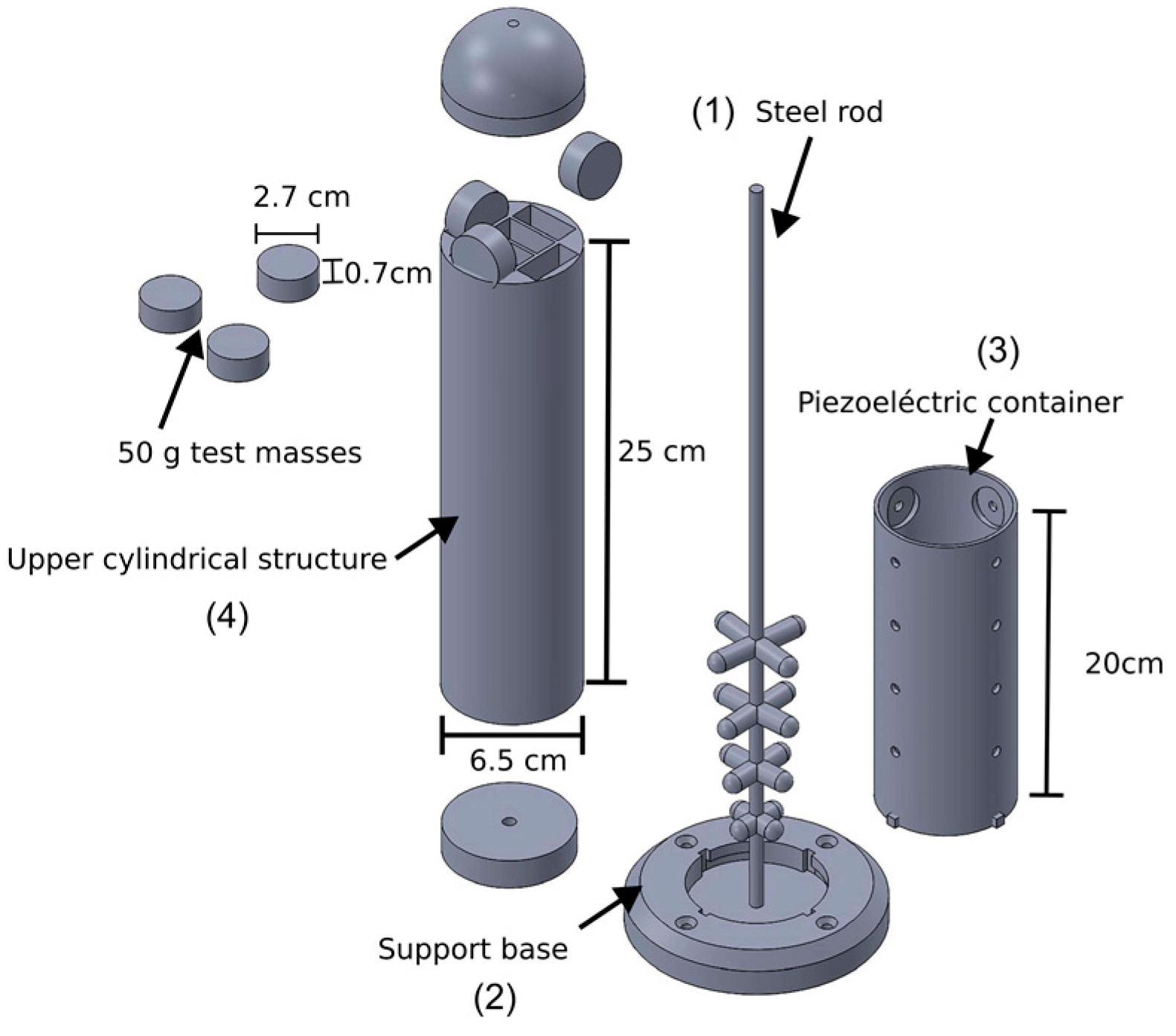
To manufacture the mast-type structure that will allow the use of mechanical energy from the vibrations of bridges and the interaction with the wind, a 3D design was made through Solid Works software and printed in PLA through a Creality Ender V2 3D printer, considering an extruder temperature of 220 °C, a bed temperature of 60 °C, a percentage of hexagonal filling of 20%, and a printing layer height of 0.28 mm. The structure of the proposed energy harvester is composed of 4 parts: the mast (a threaded steel rod with a diameter of 6.35 mm), the support base where the mast and the cylinder containing the piezoelectric disks are fixed, and the upper cylindrical structure, which is fixed to the tip of the rod and interacts with the wind through the vibration induced by the vortex. This last part has containers to place calibrated masses of 50 g. This system allows the vertical simultaneous impact of 4 stacks of piezoelectric disks with a diameter of 12 mm induced by the oscillation of the rod. The mentioned design with its dimensions can be seen in Figure 2.

2.3. Testing of Electric Power Generation

The operating principle of the proposed energy harvester is based on transforming the mechanical vibrations of a pedestrian bridge and the kinetic energy of the wind into electrical energy. The mechanical energy collected is transformed into an oscillation of the rod impacting the piezoelectric disks. This phenomenon produces electrical charges that allow a capacitor to be charged. To test the functioning of the proposed system for piezoelectric generation of energy by impact, an experimental setup was carried out (Figure 3). These tests were performed using the design shown in Figure 2 for a single piezoelectric disk without using the piezoelectric-containing cylinder to control the impact of one of the cross-type structures attached to the rod. This setup consists of a movable support for placing the force sensor and a piezoelectric transducer. The electrical energy generated by the impact of the rod on the piezoelectric disk is transformed into voltage using a charge amplifier (Figure 1a). In this first test, the force generated by the impact and the voltage obtained by the piezoelectric transducer were analyzed. Simultaneously, an accelerometer was used to detect the movement of the rod when it was stimulated. In this case, the stimulation of the rod was induced by displacing it 10° from its equilibrium axis. This displacement caused an impact force on the piezoelectric disks that was reproducible for the different test conditions. The tests were carried out three times for each of the test conditions. Steel rods of 44 cm and 88 cm with tip masses of 0 g, 100 g, and 200 g for each one were used to study the effect of such conditions on the generation of electrical energy. Subsequently, the experimental tests were repeated for charging a 1 µF capacitor using the rectifier circuit shown in Figure 1b. The response was analyzed through the oscilloscope.

2.4. Mechanical Interaction between the 3D Printing Material and the Piezoelectric Disk

To know the risk of yielding in the 3D-printed cross-type structure impacting the piezoelectric disks, the maximum contact pressure for impact from 0.1 to 55 N was calculated. The Hertz formula was applied to determine the contact area dimension (Formula (3)) and the maximum contact pressure (Formula (4)) under normal loads ranging from 0.1 to 55 N for PLA and ABS materials for comparison. F is the normal load, R is the reduced radius (4.95 mm for this case), and E * is the reduced elastic modulus. E * was calculated using Formula (5), where v 1 , v 2 and E 1 , E 2 are Poisson’s ratios and Young’s modules of contact materials, respectively. The mechanical properties used to calculate P0 are shown in Table 1.
a = 3 × F × R 4 × E * 3
P 0 = 3 × F 2 π × a 2
1 E * = 1   υ 1 2 E 1 + 1   υ 2 2 E 2

2.5. Estimation of Harvested Energy Using Multiple Piezoelectric Disks

The energy harvester shown in Figure 2 proposes a structure that allows the simultaneous impact of 4 stacks of piezoelectric disks as the rod oscillates and impacts the walls of the cylinder containing the transducers. To know the energy generation potential of the proposed system considering simultaneous impacts for 4 stacks of 25 piezoelectric transducers and the natural frequencies of oscillation of the rods, the energy accumulated in a capacitor of 1 µF for the piezoelectric disks of PZT with a 12 mm diameter was calculated using Formula (6). The calculation was performed for 1 h of stimulation for periodic impacts from 0 to 50 N and frequencies of 1.1 and 1.8 Hz for the 44 cm rod with 0 and 200 g of tip mass, and 3.3 and 5.7 Hz for the 88 cm rod with 0 and 200 g of tip mass.
E = 1 2   C × V 2

2.6. On-Site Tests of the Oscillatory Behavior of the Proposed Generator on Footbridge

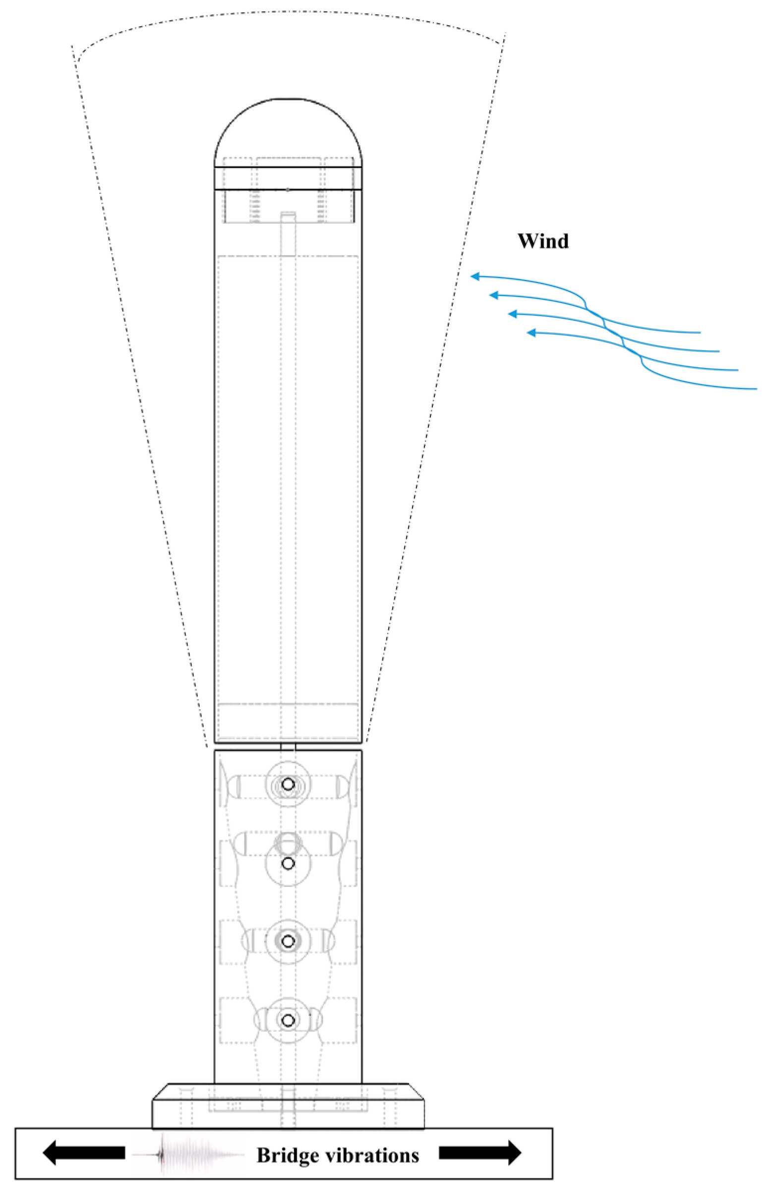
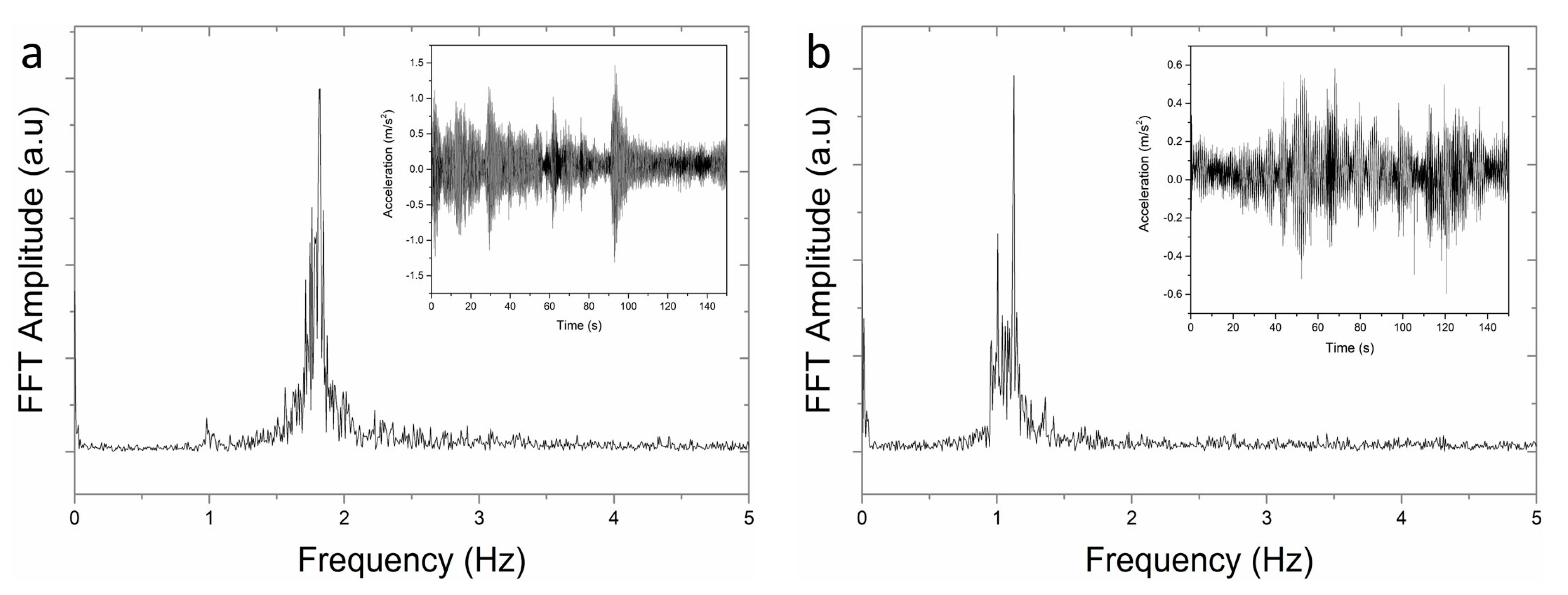
Pedestrian bridges are interesting sites for collecting mechanical energy since they are susceptible to vibrations generated by pedestrians and vehicle traffic. Furthermore, due to their height, the available wind resource is greater than that at ground level. Both stimuli generate an oscillation in the proposed structure, as exemplified in Figure 4. To analyze the energy potential obtained by the structure, the magnitude of the acceleration obtained in the structure was measured for 150 s. Subsequently, the data (5000 points) were processed through the Fourier Fast Transform to obtain the vibration frequencies of the 44 and 88 cm rods with masses of 0 g and 200 g. The tests were carried out on a pedestrian bridge located on a highway with a constant flow of vehicles.

3. Results

3.1. Characterization of Piezoelectric Transducers

The piezoelectric properties of the piezoelectric transducers used are shown in Table 2. In Table 2, the piezoelectric strain coefficient (d33), the capacitance of the piezoelectric element (Cp), the relative permittivity (εr), and the g33 coefficient can be seen. The values obtained follow the values reported in the literature, which demonstrates the validity of the piezoelectric characterization carried out.

3.2. Testing of Electric Power Generation

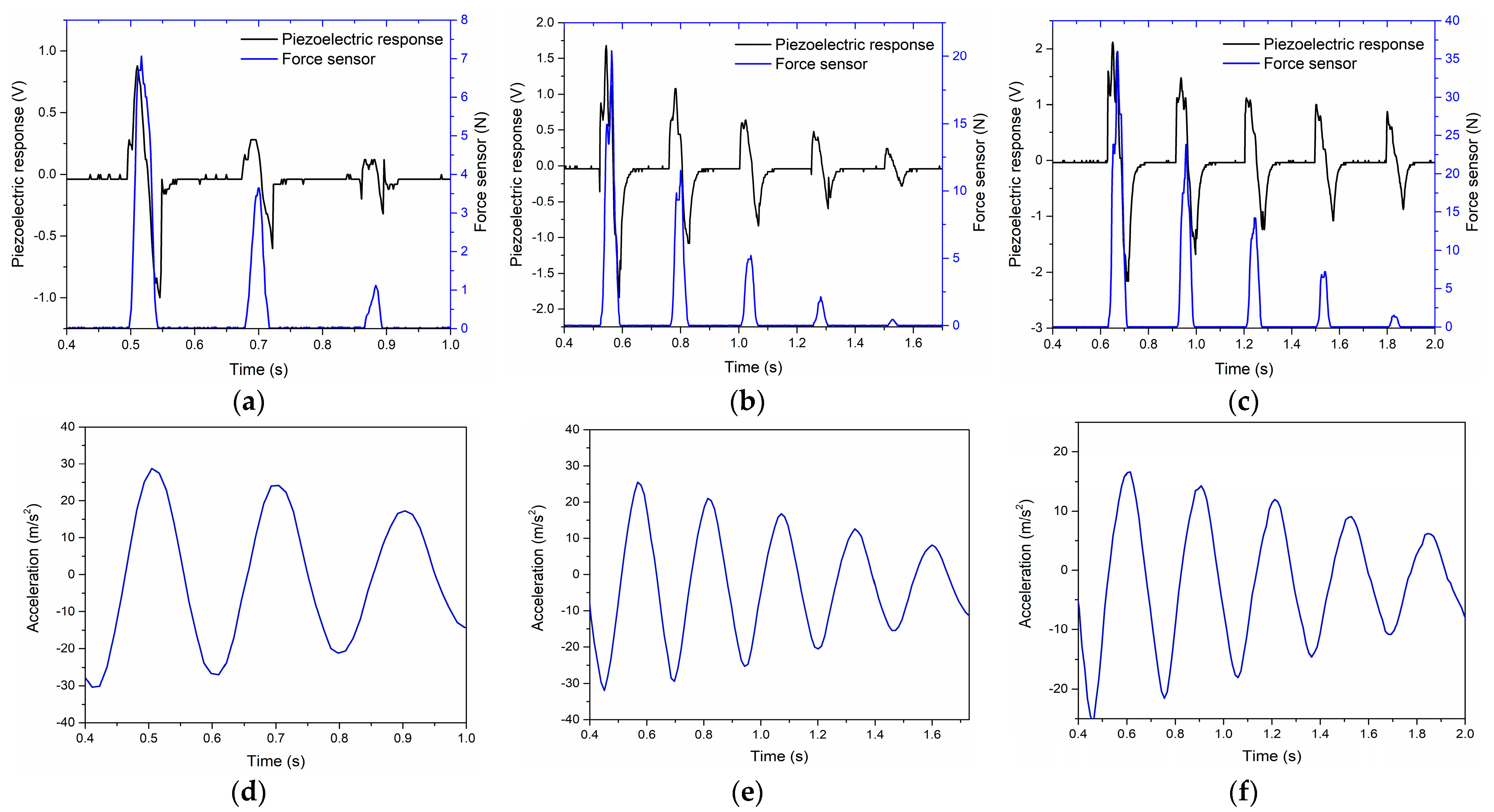
Figure 5a–c show the piezoelectric response graphs of the transducers when stimulated by the 44 cm rod. In each impact, an electrical charge is generated, and it is transformed into voltage by means of a charge amplifier. It is possible to observe the damped response of the generator as the impacts are of lower amplitude. Furthermore, it is evident that the impact force increases with increasing mass at the tip of the rods, which is also manifested by a greater generation of voltage in the piezoelectric transducer. Figure 5d–f show the general accelerations in the rod when it is displaced 10° in the same impact axis. The oscillation frequency decreases as the tip mass of the rod increases (from 5.8 Hz to 3.5 Hz); this behavior is expected for an oscillating rod with tip mass.
Figure 6a–c show the piezoelectric response graphs of the transducers when stimulated by the 88 cm rod. In each impact, an electrical charge is generated that is transformed into voltage by means of a charge amplifier. It is possible to observe the damped response of the generator as the impacts are of lower amplitude; however, the damping is less than that of the 44 cm rod. It is also evident that the impact force increases with increasing mass at the tip of the rods. Unlike the response obtained for the 44 cm rod, in this case, the voltage in the piezoelectric transducer decreased as the mass of the tip of the rod increased. Figure 6d–f show the accelerations generated in the rod when it is displaced 10° in the same impact axis. The oscillation frequency decreases as the mass at the tip of the rod increases (from 2.1 Hz to 1.4 Hz), which is in line with what is expected for an oscillating rod with mass at the tip. In this test, it is possible to observe how the oscillation is maintained for a greater amount of time.
Figure 7 shows the charge of a 1 µF capacitor connected to the rectified piezoelectric voltage (rectifier circuit shown in Figure 1), while it is stimulated by the oscillating rod, as shown in Figure 5 and Figure 6. In Figure 7a, it is observed that the 44 cm rod with a tip mass of 200 g charges the capacitor at a higher voltage. This corresponds to the voltage amplitude observed in the graphs shown in Figure 5. In Figure 7b, the charge of the capacitor for the 88 cm rod can be seen; in this case, the behavior is similar for the different test masses, which is consistent with the results shown in Figure 6. The proposed structure produced 0.215 µJ of energy after 3 s of testing for the 44 cm rod and 0.337 µJ of energy after 14 s of testing for the 88 cm rod.

3.3. Comparison of the Mechanical Behavior of the Impacting Material

The maximum contact pressure for the PZT disk varies with the applied load. The graph in Figure 8 details the relationship between the contact pressure and the normal load, providing a precise understanding of how these materials interact under different load conditions. This analysis is essential for predicting potential failures and optimizing the use of PLA and ABS materials impacting the PZT disks. Considering the yield strength properties of PLA and ABS at 60 MPa and 43 MPa, respectively, it can be concluded that PLA resists higher impact forces. Furthermore, PLA is a biodegradable polymer, which makes it more convenient to use for this application.

3.4. Simulated Behavior of the Power Generation System

Figure 9 shows the estimated production of energy after 1 h of continuous impacts from 0 to 50 N, considering the natural frequencies of oscillation of the rod with 0 and 200 g tip masses. The maximum energy harvested for periodic impacts at 1.1 Hz, 1.8 Hz, 3.3 Hz, and 5. 7 Hz at 50 N were 1.9 mJ, 3.2 mJ, 5.9 mJ, and 10.4 mJ, respectively.

3.5. On-Site Tests of the Oscillatory Behavior of the Proposed Generator on Footbridge

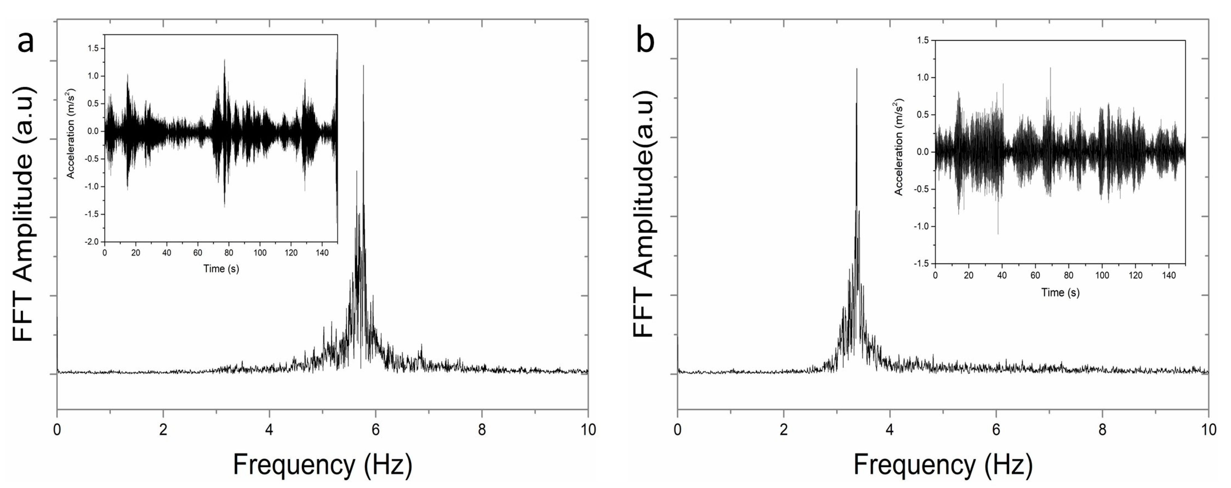
Figure 10 and Figure 11 show the accelerations in the test rods caused by the vibration of the test bridge and the wind interacting with the proposed cylindrical structure. Resonance frequencies of 5.7 Hz and 3.3 Hz were obtained for the 44 cm rod with a mass of 0 g and 200 g, respectively. Resonance frequencies of 1.8 Hz and 1.1 Hz were obtained for the 88 cm rod with a mass of 0 g and 200 g, respectively. The resonance frequencies correspond to the oscillation frequencies obtained in the laboratory tests (Figure 5 and Figure 6).

4. Discussion

4.1. Testing of Electric Power Generation

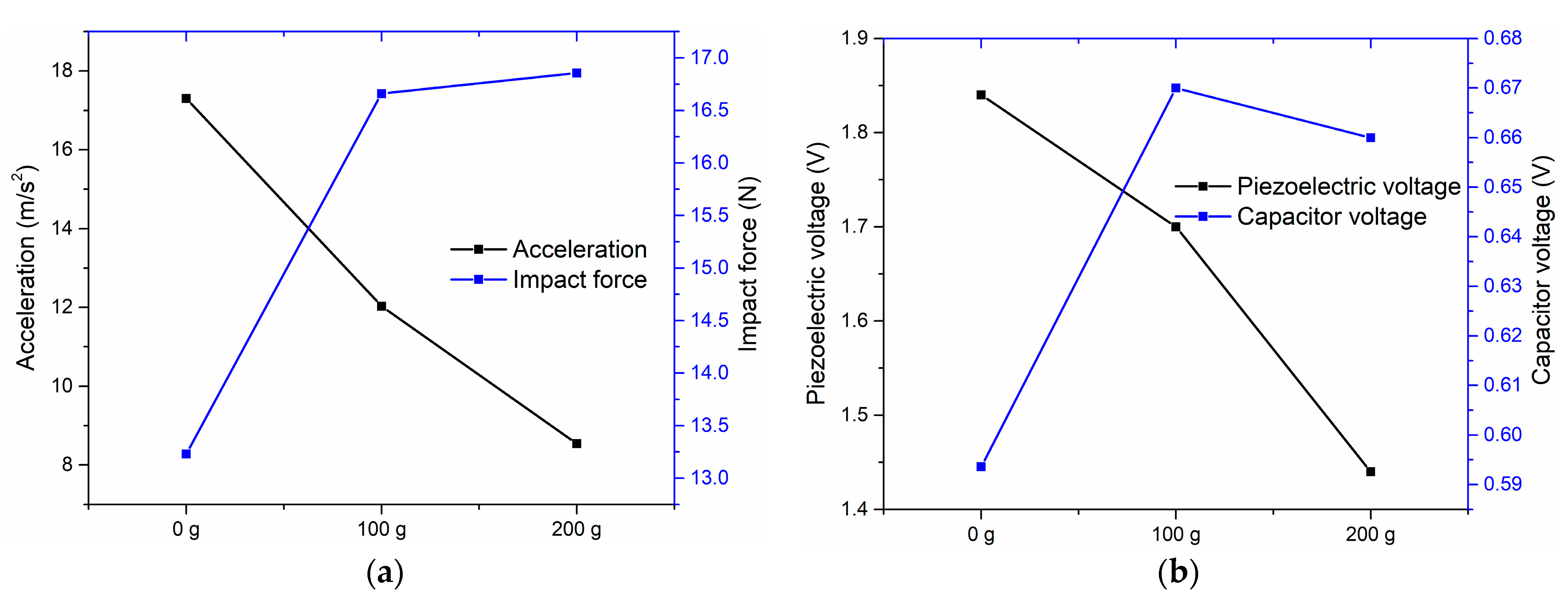
Figure 12 shows a comparison of the maximum amplitudes obtained from the electrical generation tests for the 44 cm rod. In Figure 12a, it can be seen that the acceleration of the rod decreases as the tip mass of the rod increases. Despite this behavior, the impact force increases since it is directly related to the oscillating mass. The voltage produced by the transducer increases as the impact force increases, which follows the piezoelectric response to force stimuli. As there is a higher voltage, there is also a greater storage of energy in the capacitor. The evidence obtained is important because although the impact frequency decreases as the tip mass of the rod increases, the increasing impact force generates more energy. It will be necessary to do tests in the future to find the optimal mass that produces the greatest amount of energy.
Figure 13 shows a comparison of the maximum amplitudes obtained from electrical generation tests for the 88 cm rod. In Figure 13a, it can be seen that the acceleration of the rod decreases as the mass at the tip of the rod increases, in a behavior similar to that obtained for the 44 cm rod. For these conditions, the impact force also increases since it is directly related to the oscillating mass. In Figure 13b, an interesting result can be observed: the voltage produced by the transducer decreases as the impact force increases, which does not correspond to the usual piezoelectric response to force stimuli. The results shown in Figure 6d–f can explain the observed phenomenon. The acceleration in the negative direction presents an imbalance with respect to that in the positive direction. This behavior was not observed in the oscillations of the 44 cm rod (Figure 5d,e). In addition, in the second mode shape of the vibrations of the rod used as an energy harvester, the increase in rod tip mass produces a decrease in rod displacement, resulting in lower power, as reported in the literature [24]. In addition, as observed in the deformed acceleration plots in Figure 6, a second mode vibration may have occurred in the long rod with a higher tip mass, which reduced power generation. The nature of the resistive force sensor with respect to the piezoelectric response could explain the contradictory response of the lower voltage generated for a higher impact force. Since there is a lower voltage, there is also less energy storage in the capacitor; however, the frequency at which the piezoelectric transducer is stimulated is also important, so the response observed in Figure 13 b can be explained by this fact.

4.2. Simulated Behavior of the Power Generation System

The harvested energy obtained by the piezoelectric transducers when impacted by periodic 50 N forces is similar to the piezoelectric response of other energy harvesting systems, as observed in Table 3, which is evidence of the potential of the proposed structure for the generation of clean energy by taking advantage of the mechanical energy present in the vibrations of pedestrian bridges and the vibration caused by the resonance effect of the wind.

4.3. On-Site Tests of the Oscillatory Behavior of the Proposed Generator on Footbridge

The results observed in Figure 10 and Figure 11 show a coincidence in the oscillation frequencies generated in the test rods when they are mechanically stimulated. However, the accelerations obtained in the rods are around 20 times smaller than those obtained in the laboratory with displacements of 10°. This fact is manifested by the response of the piezoelectric transducer when stimulated with a lower acceleration. In preliminary tests, open-circuit voltages for the transducers used were between 50 and 100 mV. This information is useful for proposing new designs with different rod lengths, a greater amount of test masses, and other geometric structures that allow maximizing the acceleration obtained in the rods by the interaction of the system with the vibrations of the bridge and the wind.

5. Conclusions

This study demonstrates the potential of harnessing mechanical vibrations in bridges to generate clean electrical energy using piezoelectric energy harvesters. By employing a rod with a tip mass to stimulate piezoelectric transducers through impact, the experimental setup achieved an energy production of 0.337 µJ over 14 s and an estimated 10.4 mJ after one hour under specified conditions, which is consistent with other studies on piezoelectric energy harvesters. In addition, the design of the proposed energy harvester can be amplified in size, which would allow stimulating a larger number of piezoelectric disks of larger diameter and simultaneously generating a larger amount of energy. These findings validate the system’s functionality as an energy harvester and highlight its capability to supply power to low-consumption electronic devices. The results obtained in this research will allow the design of the proposed device to be redirected to take advantage of environmental mechanical energy. Future research will focus on optimizing the use of bridge vibrations and vortex-induced vibrations (VIV) to further enhance energy production for sustainable low-power applications.

Author Contributions

Investigation, Writing—Original Draft Preparation, Writing—Review and Editing, Funding Acquisition, Validation, Supervision, and Formal Analysis, D.H.-R.; Investigation, Writing—Original Draft Preparation, Writing—Review and Editing, and Formal Analysis, M.A.I.-H.; Software and Validation, D.A.C.-C.; Visualization and Validation, J.M.J.-P. and D.S.-L.; Writing—Review and Editing and Formal Analysis, C.I.L.-A. All authors have read and agreed to the published version of the manuscript.

Funding

This research was funded by Tecnológico Nacional de México (TECNM) and Universidad Autónoma Metropolitana—Azcapotzalco (UAM-A).

Informed Consent Statement

Not applicable.

Data Availability Statement

Not applicable.

Acknowledgments

We appreciate the technical support in the laboratory tests from Diego Josue Martinez Méndez and Pablo David Rivera Guillén.

Conflicts of Interest

The authors declare no conflicts of interest.

References

  1. Pradeesh, E.L.; Udhayakumar, S.; Vasundhara, M.G.; Kalavathi, G.K. A Review on Piezoelectric Energy Harvesting. Microsyst. Technol. 2022, 28, 1797–1830. [Google Scholar] [CrossRef]
  2. Sezer, N.; Koç, M. A Comprehensive Review on the State-of-the-Art of Piezoelectric Energy Harvesting. Nano Energy 2021, 80, 105567. [Google Scholar] [CrossRef]
  3. Ding, G.; Zhao, X.; Wang, J.; Xu, C. Vibration Energy Harvesting from Roads under Traffic Loads. Road Mater. Pavement Des. 2020, 21, 780–799. [Google Scholar] [CrossRef]
  4. Kütt, L.; Millar, J.; Karttunen, A.; Lehtonen, M.; Karppinen, M. Thermoelectric Applications for Energy Harvesting in Domestic Applications and Micro-Production Units. Part I: Thermoelectric Concepts, Domestic Boilers and Biomass Stoves. Renew. Sustain. Energy Rev. 2018, 98, 519–544. [Google Scholar] [CrossRef]
  5. Priya, S.; Song, H.C.; Zhou, Y.; Varghese, R.; Chopra, A.; Kim, S.G.; Kanno, I.; Wu, L.; Ha, D.S.; Ryu, J.; et al. A Review on Piezoelectric Energy Harvesting: Materials, Methods, and Circuits. Energy Harvest. Syst. 2019, 4, 3–39. [Google Scholar] [CrossRef]
  6. Liu, Y.; Shang, S.; Mo, S.; Wang, P.; Wang, H. Eco-Friendly Strategies for the Material and Fabrication of Wearable Sensors. Int. J. Precis. Eng. Manuf.-Green Technol. 2020, 8, 1323–1346. [Google Scholar] [CrossRef]
  7. Bryant, M.; Wolff, E.; Garcia, E. Aeroelastic Flutter Energy Harvester Design: The Sensitivity of the Driving Instability to System Parameters. Smart Mater. Struct. 2011, 20, 125017. [Google Scholar] [CrossRef]
  8. Kwon, S.D. A T-Shaped Piezoelectric Cantilever for Fluid Energy Harvesting. Appl. Phys. Lett. 2010, 97, 164102. [Google Scholar] [CrossRef]
  9. Du, X.; Zhang, M.; Chang, H.; Wang, Y.; Yu, H. Micro Windmill Piezoelectric Energy Harvester Based on Vortex-Induced Vibration in Tunnel. Energy 2022, 238, 121734. [Google Scholar] [CrossRef]
  10. Rezaei-Hosseinabadi, N.; Tabesh, A.; Dehghani, R.; Aghili, A. An Efficient Piezoelectric Windmill Topology for Energy Harvesting from Low-Speed Air Flows. IEEE Trans. Ind. Electron. 2015, 62, 3576–3583. [Google Scholar] [CrossRef]
  11. Wang, J.; Gu, S.; Abdelkefi, A.; Zhang, M.; Xu, W.; Lai, Y. Piezoelectric Energy Harvesting from Flow-Induced Vibrations of a Square Cylinder at Various Angles of Attack. Smart Mater. Struct. 2021, 30, 8LT02. [Google Scholar] [CrossRef]
  12. Naqvi, A.; Ali, A.; Altabey, W.A.; Kouritem, S.A. Energy Harvesting from Fluid Flow Using Piezoelectric Materials: A Review. Energies 2022, 15, 7424. [Google Scholar] [CrossRef]
  13. Zhang, Y.; Cai, S.C.S.; Deng, L. Piezoelectric-Based Energy Harvesting in Bridge Systems. J. Intell. Mater. Syst. Struct. 2014, 25, 1414–1428. [Google Scholar] [CrossRef]
  14. Zhang, Z.; Xiang, H.; Tang, L.; Yang, W. A Comprehensive Analysis of Piezoelectric Energy Harvesting from Bridge Vibrations. J. Phys. D Appl. Phys. 2022, 56, 14001. [Google Scholar] [CrossRef]
  15. Sheng, W.; Xiang, H.; Zhang, Z.; Yuan, X. High-Efficiency Piezoelectric Energy Harvester for Vehicle-Induced Bridge Vibrations: Theory and Experiment. Compos. Struct. 2022, 299, 116040. [Google Scholar] [CrossRef]
  16. Wang, H.; Jasim, A.; Chen, X. Energy Harvesting Technologies in Roadway and Bridge for Different Applications—A Comprehensive Review. Appl. Energy 2018, 212, 1083–1094. [Google Scholar] [CrossRef]
  17. Clementi, G.; Cottone, F.; Di Michele, A.; Gammaitoni, L.; Mattarelli, M.; Perna, G.; López-Suárez, M.; Baglio, S.; Trigona, C.; Neri, I. Review on Innovative Piezoelectric Materials for Mechanical Energy Harvesting. Energies 2022, 15, 6227. [Google Scholar] [CrossRef]
  18. Yang, H.; Wei, Y.; Zhang, W.; Ai, Y.; Ye, Z.; Wang, L. Development of Piezoelectric Energy Harvester System through Optimizing Multiple Structural Parameters. Sensors 2021, 21, 2876. [Google Scholar] [CrossRef] [PubMed]
  19. Bao, B.; Wang, Q.; Wu, N.; Zhou, S. Hand-Held Piezoelectric Energy Harvesting Structure: Design, Dynamic Analysis, and Experimental Validation. Measurement 2021, 174, 109011. [Google Scholar] [CrossRef]
  20. Mhiri, M.T.; Chouchane, M.; Guerich, M.; Larbi, W. Modeling and Analysis of a Macro-Fiber Piezoelectric Bimorph Energy Harvester Operating in D33-Mode Using Timoshenko Theory. Mech. Adv. Mater. Struct. 2024, 1–15. [Google Scholar] [CrossRef]
  21. Ju, S.; Ji, C.H. Impact-Based Piezoelectric Vibration Energy Harvester. Appl. Energy 2018, 214, 139–151. [Google Scholar] [CrossRef]
  22. Wang, J.; Zhao, W.; Su, Z.; Zhang, G.; Li, P.; Yurchenko, D. Enhancing Vortex-Induced Vibrations of a Cylinder with Rod Attachments for Hydrokinetic Power Generation. Mech. Syst. Signal. Process. 2020, 145, 106912. [Google Scholar] [CrossRef]
  23. Zhang, M.; Zhang, C.; Abdelkefi, A.; Yu, H.; Gaidai, O.; Qin, X.; Zhu, H.; Wang, J. Piezoelectric Energy Harvesting from Vortex-Induced Vibration of a Circular Cylinder: Effect of Reynolds Number. Ocean Eng. 2021, 235, 109378. [Google Scholar] [CrossRef]
  24. Borowiec, M.; Bochenski, M.; Litak, G.; Teter, A. Analytical Model and Energy Harvesting Analysis of a Vibrating Slender Rod with Added Tip Mass in Three-Dimensional Space. Eur. Phys. J. Spec. Top. 2021, 230, 3581–3590. [Google Scholar] [CrossRef]
  25. Selleri, G.; Poli, F.; Neri, R.; Gasperini, L.; Gualandi, C.; Soavi, F.; Fabiani, D. Energy Harvesting and Storage with Ceramic Piezoelectric Transducers Coupled with an Ionic Liquid-Based Supercapacitor. J. Energy Storage 2023, 60, 106660. [Google Scholar] [CrossRef]
  26. Hwang, G.T.; Annapureddy, V.; Han, J.H.; Joe, D.J.; Baek, C.; Park, D.Y.; Kim, D.H.; Park, J.H.; Jeong, C.K.; Park, K.I.; et al. Self-Powered Wireless Sensor Node Enabled by an Aerosol-Deposited PZT Flexible Energy Harvester. Adv. Energy Mater. 2016, 6, 1600237. [Google Scholar] [CrossRef]
  27. Wang, C.; Wang, S.; Gao, Z.; Song, Z. Effect Evaluation of Road Piezoelectric Micro-Energy Collection-Storage System Based on Laboratory and on-Site Tests. Appl. Energy 2021, 287, 116581. [Google Scholar] [CrossRef]
  28. Staaf, H.; Matsson, S.; Sepheri, S.; Köhler, E.; Daoud, K.; Ahrentorp, F.; Jonasson, C.; Folkow, P.; Ryynänen, L.; Penttila, M.; et al. Simulated and Measured Piezoelectric Energy Harvesting of Dynamic Load in Tires. Heliyon 2024, 10, e29043. [Google Scholar] [CrossRef]
Figure 1. (a) Charge amplifier and (b) full bridge rectifier circuits used to characterize the piezoelectric disks and store the harvested energy.
Cleantechnol 06 00046 g001
Figure 2. Design of the proposed structure for the generation of electrical energy from mechanical energy using simultaneous impacts on piezoelectric stacks. (1) Mast, (2) support base, (3) cylinder containing the piezoelectric disks, and (4) upper cylindrical structure.
Cleantechnol 06 00046 g002
Figure 3. Experimental setup for piezoelectric response to rod impact.
Cleantechnol 06 00046 g003
Figure 4. Interaction of bridge vibrations and wind with the proposed electrical generator.
Cleantechnol 06 00046 g004
Figure 5. Piezoelectric response and impact force obtained from 44 cm long rods with (a) 0 g, (b) 100 g, and (c) 200 g tip masses. Acceleration response from oscillating 44 cm long rods with (d) 0 g, (e) 100 g, and (f) 200 g tip masses.
Cleantechnol 06 00046 g005
Figure 6. Piezoelectric response and impact force obtained from 88 cm long with (a) 0 g, (b) 100 g and (c) 200 g tip masses. Acceleration response from 88 cm long oscillating rods with (d) 0 g, (e) 100 g, and (f) 200 g tip masses.
Cleantechnol 06 00046 g006
Figure 7. Voltage in the capacitor and the stored energy shown at the end of the curves were obtained by stimulating the piezoelectric transducers with the impact of the (a) 44 cm long oscillating rod and (b) 88 cm long oscillating rod, each with different tip masses.
Cleantechnol 06 00046 g007
Figure 8. Mechanical behavior of the polymer structure for impacts from 0 to 50 N.
Cleantechnol 06 00046 g008
Figure 9. Estimated production of energy obtained after 1 h of operation considering 4 stacks of 25 piezoelectric disks each for (a) 1.1 Hz, (b) 1.8 Hz, (c) 3.3 Hz, and (d) 5.7 Hz of periodic impacts from 0 to 50 N.
Cleantechnol 06 00046 g009
Figure 10. (a) The resonance frequency of the 44 cm rod with a mass at the tip of 0 g when stimulated by the vibration of the pedestrian bridge and the interaction with the wind (Inset: accelerations obtained during a recording of 150 s). (b) The resonance frequency of the 44 cm rod with a tip mass of 200 g when stimulated by the pedestrian bridge vibration and the interaction with the wind (Inset: accelerations obtained during a 150 s recording).
Cleantechnol 06 00046 g010
Figure 11. (a) The resonance frequency of the 88 cm rod with a mass at the tip of 0 g when stimulated by the vibration of the pedestrian bridge and the interaction with the wind (Inset: accelerations obtained during a recording of 150 s). (b) The resonance frequency of the 88 cm rod with a tip mass of 200 g when stimulated by the pedestrian bridge vibration and the interaction with the wind (Inset: accelerations obtained during a 150 s recording).
Cleantechnol 06 00046 g011
Figure 12. (a) Acceleration and maximum impact force; and piezoelectric and (b) capacitor voltage obtained from the interaction of the piezoelectric transducers and the 44 cm oscillating rod.
Cleantechnol 06 00046 g012
Figure 13. (a) Acceleration and maximum impact force; and piezoelectric and (b) capacitor voltage obtained from the interaction of the piezoelectric transducers and the 88 cm oscillating rod.
Cleantechnol 06 00046 g013
Table 1. Mechanical properties of the contact materials.
MaterialYoung’s Modulus (Gpa)Poisson’s RatioYield Strength (MPa)
Brass89.60.35379
PZT520.34150
ABS1.90.3343
PLA2.30.3860
Table 2. Piezoelectric and dielectric properties of the transducers.
d33 [pC∙N−1]Cp [nF]εrg33 [ mV∙m∙N−1]
22412.5124920.2
Table 3. Comparison of the stored energy for different piezoelectric energy harvesters.
Piezoelectric MaterialCharging TimeApplied Force (N)Stored Energy (mJ)Ref
PZT2 h85 N110[25]
PZT16 h-44[26]
PZT3 h-76.3[27]
PVDF200 s-0.023[28]
PZT1 h50 N10.4This work
Disclaimer/Publisher’s Note: The statements, opinions and data contained in all publications are solely those of the individual author(s) and contributor(s) and not of MDPI and/or the editor(s). MDPI and/or the editor(s) disclaim responsibility for any injury to people or property resulting from any ideas, methods, instructions or products referred to in the content.