Article

Thirty-Five Years of Non-Destructive Testing in Santa Maria Della Croce di Roio Church, L’Aquila, Italy (A.D. 1625): Assessing the Impact of Restoration and Seismic Events

1
Department of Industrial and Information Engineering and Economics, University of L’Aquila, P.le E. Pontieri 1, I-67100 L’Aquila, Italy
2
MIMARC Srl, Via Giosuè Carducci 30, I-67100 L’Aquila, Italy
3
Department of Civil, Construction−Architectural and Environmental Engineering, University of L’Aquila, P.le E. Pontieri 1, I-67100 L’Aquila, Italy
4
Heritechne Center, University of L’Aquila, P.le E. Pontieri 1, I-67100 L’Aquila, Italy
*
Author to whom correspondence should be addressed.
Heritage 2025, 8(11), 446; https://doi.org/10.3390/heritage8110446
Submission received: 18 September 2025 / Revised: 15 October 2025 / Accepted: 21 October 2025 / Published: 23 October 2025
(This article belongs to the Section Cultural Heritage)

Abstract

This study presents the results of over thirty years of non-destructive testing (NDT) in a historic church, providing an unprecedented time analysis of the structural and material integrity of the building and its works of art. During this time, the church has undergone several restorations and two major seismic events. The diagnostics, which include a calibrated mix of established and advanced micro-destructive and non-destructive (NDT) techniques such as X-ray fluorescence, holographic interferometry, electronic speckle pattern interferometry (ESPI), infrared thermography, and IR reflectography, provide critical insights into the impact of the restoration interventions and the earthquakes on the church’s artistic heritage. The results indicate varying degrees of effectiveness of the restoration efforts, highlighting both areas of successful conservation and emerging vulnerabilities. This long-term study highlights the importance of continuous monitoring and its integration with NDT in identifying the effects of time and strong events occurring during the life of artworks that influence their state of conservation.

1. Introduction

According to UNESCO [1], “Heritage is our legacy from the past, what we live with today, and what we pass on to future generations”. UNESCO itself recognises the broadening of heritage definitions, its increasing significance, and its connection with sustainable development [2].
The conservation of cultural heritage buildings, in particular those of artistic and/or historic value, is a very difficult task, because these buildings are history witnesses and possess architectural value as well as invaluable artworks, both outside and inside. Therefore, effective preservation strategies must be a balance between maintaining the building’s structural integrity and safeguarding the artworks it houses.
A sustainable protection strategy is not possible without a systematic documentation of its state over time.
Among the various conservation techniques employed in cultural heritage management, non-destructive testing has become a key methodology.
In particular, non-destructive optical techniques have a crucial role because they are intrinsically no-contact and full-field [3,4].
Many methods have been proposed and are widely employed, using different wavelengths of radiation, such as holographic and speckle methods [5,6,7,8,9,10], IR reflectography and thermography [11,12,13,14,15,16], OCT [17,18], Teraherz [19], and XRF [20].
In many cases, the combined use of different techniques leads to greater diagnostic efficiency, for instance coupling thermography and georadar [21], thermography and holographic interferometry [22,23,24], and destructive and non-destructive techniques [25]. In particular, in this paper a multidisciplinary approach is reported as a significant example of a diagnostic survey effected on a historic church, Santa Maria della Croce (Roio, AQ, Italy), planned at the beginning of the 1990s by the Las.E.R. Laboratory of the University of L’Aquila (Italy). This study is very peculiar because of the long-term monitoring; furthermore, throughout this period, the church underwent several restoration projects aimed at maintaining its structural stability and preserving its artistic treasures. Additionally, during the investigation period, the church was subjected to two major seismic events. By applying a variety of NDT methods, this study provides a rare, time-based analysis, offering a comprehensive view of how both restoration efforts and natural disasters have influenced the conservation of this cultural heritage site.

1.1. The Church of Santa Maria Della Croce in Roio

The sanctuary of Madonna di Roio (Figure 1), also called Santa Maria della Croce, was built to replace an older chapel dedicated to St. Leonard, which dates back to at least 1221. This chapel was once part of a hospital that later became a Benedictine convent. In the late 1500s, strong devotion to the Virgin Mary developed in the area, leading to the construction of the current sanctuary in 1625, dedicated to St. Mary of the Cross (Santa Maria della Croce). The story behind the sanctuary is tied to a local legend from the late 1500s. The sanctuary, projected by Bernini’s school and completed with a tower bell (1669) and a façade (1673), features many original elements, including the high altar, portals, flooring, marble facings, and baptismal font; a 15th-century fresco and the statue of St. Leonard are preserved from the original chapel [26].
Among the several artworks housed in the church, particular attention has been dedicated to the wooden statue of the Madonna and the frescoes by Giacomo Farelli.
The Virgin with her Child (Figure 2) is a 14th-century wooden statue, probably originating outside of the Abruzzo region, in accordance with the tradition. The statue is made of cedar wood; once carved, it was covered by a preparation layer, on which a polychrome coating was applied. A visual comparison over the last 100 years shows slight iconographic changes due to restoration work (see Figure 2). More details about this artwork are given in [27].
The frescoes (see an example in Figure 3) are found on two walls and on the vault, and were executed between 1660 and 1667 by Giacomo Farelli, one of the greatest masters of the Neapolitan Baroque. These frescoes have undergone various changes and deterioration, even running the risk of being destroyed. Giacomo Farelli (or Farrelli) was born in Rome (Italy) in 1629 and died in Naples (Italy) in 1706. He studied under Andrea Vaccaro (1604–1670) and was influenced by Luca Giordano (1634–1705), Guido Reni (1575–1642), and Domenichino (1581–1641) [28].
Giacomo Farelli is a singular figure in the history of art. Farelli was very successful and was considered one of the masters of his time; he worked mainly in Naples and in Abruzzo (Italy), he became a Knight of the Order of Malta, and for several years he was governor of the city of L’Aquila. However, much of his work was subsequently lost or destroyed, his name was forgotten, and his work was only recently rediscovered [29].

1.2. Chronology of Seismic Events and Restorations

As mentioned above, the present study is particularly interesting because of its temporal length, which includes two significant seismic events and several restoration works. In addition, the systematic testing of new techniques in situ has transformed the church of Santa Maria della Croce into a kind of living lab for cultural heritage diagnostics.
The city of L’Aquila is located in an area of high seismic risk and has suffered many earthquakes in its history.
The Italian Macroseismic Database (DBMI15), version 4.0, provides data for Italian earthquakes, with maximum intensity ≥5, in the 1000–2020 time window.
DBMI15 lists 125 earthquakes in L’Aquila since 1625, the date of construction of the current sanctuary; of the three most destructive earthquakes in L’Aquila’s history, two occurred during the sanctuary’s lifetime: in February 1703 (the Big Quake; moment magnitude 6.7, epicentral intensity 10) and in April 2009 (moment magnitude 6.3, epicentral intensity 9–10). Significant damage was also induced by the Marsica Quake of September 1915 (moment magnitude 5.07, epicentral intensity 11).
During the time considered in this study, the church suffered the effects of the 2009 earthquake and of the 2016–2017 earthquake sequence in Central Italy (strongest quake October 2016, moment magnitude 6.61) [30]. The 2009 quake induced severe injuries in the top of the façade, the vaults of the nave, the vaults and walls of the transept, and the vaults of the apse.
An initial restoration was carried out in the early 1990s to repair frescoes that had been degraded by time and carelessness. Following the 2009 earthquake, major restoration work was required to repair structural damage to the vaults and walls, as well as to the artworks (statues, frescoes, and decorative features). A third round of restoration work was finally necessary after the 2016–2017 earthquakes.

2. Materials and Methods

The diagnostics include a calibrated mix of established and advanced methods.
In this section we shall give a very brief description of the main diagnostic techniques applied to the church and to the artworks it houses. The main focus is on full-field NDT. For more information, the reader is referred to the bibliography.

2.1. Holographic Interferometry (HI)

Holographic interferometry is the most significant application of holography, which is a method for recording both the intensity and the phase of a light wave. Because of this, holography is able to record virtually indistinguishable (i.e., three-dimensional) copies, called holograms, of a real object [31].
HI, obtained by suitably superimposing two holograms, enables objects to be compared at different times, highlighting differences with a sensitivity of fractions of a micron.
The result of holographic interferometry is sometimes called an interferogram and shows an image of the object covered by black and white lines called fringes. The pattern of these fringes can reveal the deformation undergone and the presence of subsurface defects. First introduced in mechanics in the mid-1960s [31], holographic interferometry has been used to examine works of art since the early 1970s [5,6,32].
The technique’s main features are excellent image quality, high sensitivity, and preservation of iconographic details. Therefore, positioning the defects in relation to the artwork is easy.
Despite these positive features, classic HI has never become a standard tool for diagnosing cultural heritage. The main reasons for this were technical and logistical difficulties. From the technical point of view, the process required glass plates, coated with photographic emulsion, exposed to a laser light, developed and then viewed with a laser source; it was a long, expensive, and complex process. From a logistical point of view, it was necessary to record and view holograms in the dark using anti-vibration tables.
In summary, despite offering excellent diagnostic capabilities and image quality, traditional holographic interferometry has virtually never left research laboratories [33].

2.2. Electronic Speckle Pattern Interferometry (ESPI)

Electronic speckle pattern interferometry (also called digital speckle pattern interferometry (DSPI), or TV-Holography) was one of the techniques proposed to overcome the difficulties of holographic interferometry [6].
ESPI uses the typical granularity (speckle) of images obtained with a laser source to obtain information. Images are recorded by digital cameras and processed in real time. Being less sensitive than HI to environmental vibrations, ESPI is much more practical for real-world conditions, i.e., outside laboratories [5,34,35].
In summary, ESPI made interferometry more accessible and practical, as it is cheaper and easier to implement with respect to HI and it can work outside laboratories.
However, its sensitivity is slightly lower, its image quality is much poorer, and iconographic details are lost. Thus, positioning the defects in relation to the artwork is difficult.

2.3. IR Thermography (IRT)

Infrared (IR) thermography (IRT) is a widely used non-destructive testing technique [36] that captures the thermal radiation emitted by objects to measure temperature variations on their surfaces. The principle behind this technique is based on the fact that all materials emit infrared radiation proportional to their temperature (Planck’s law), and differences in thermal conductivity, heat capacity, or layer thickness result in localised temperature variations that can be detected by thermal cameras. Such temperature contrasts are particularly useful in identifying subsurface defects like delaminations, voids, moisture ingress, or areas with material heterogeneity, which may not be visible through traditional visual inspection. This detection requires a temperature gradient that may be induced by the sun, by climatic conditions, or by a suitable excitation (e.g., infrared lamps, hot air, etc.) [36]. In cultural heritage conservation, IRT has found significant applications in examining architectural structures [37], frescoes [22,38], mosaics [39,40], and painted panels [22,41]. It enables conservators to non-invasively detect moisture accumulation, structural detachments, and cracking by observing thermal anomalies either during passive monitoring or following controlled thermal excitation.

2.4. IR Reflectography (IRR)

Infrared (IR) reflectography (IRR) [42,43,44] is a non-invasive diagnostic imaging technique widely employed in the field of cultural heritage. It enables the visualisation of subsurface features in paintings, particularly underdrawings, compositional changes (pentimenti), and earlier restorations, which are otherwise invisible to the naked eye. IRR relies on the capacity of infrared radiation (IR) to penetrate paint layers that are typically opaque to visible light. The depth of infrared penetration depends on the thickness of the paint layers, the chemical composition of the pigments, and the wavelength. While some pigments, such as carbon black, absorb IR strongly and appear dark in reflectograms, others—especially lighter or low-opacity pigments—allow partial transmission of IR, facilitating the imaging of underdrawings executed with IR-absorbent media. Despite the potential of IRR, the technique’s effectiveness is significantly influenced by the type and composition of the artwork’s pigments. For this reason, it is important to integrate IR reflectography with complementary diagnostic techniques [44,45,46].

2.5. Special Photographic Techniques

Special photographic techniques [47] are simple but effective non-invasive imaging methods commonly employed in the investigation, documentation, and conservation of cultural heritage objects. Their principal value lies in their ability to reveal material and structural features that are not visible under normal lighting conditions, thus supporting the work of conservators and art historians in understanding the composition, state of conservation, and history of an artwork. Among special photographic techniques, raking light photography (RAK) and ultraviolet fluorescence (UVF) photography are widely used.
RAK is a diagnostic method that involves illuminating the object’s surface with light almost parallel to the surface itself, thus revealing its deformations and irregularities [48]. UVF exploits the interaction between UV radiation—typically in the UV-A range (320–400 nm)—and the surface of the object. UV light causes certain materials (such as varnishes, resins, or modern pigments) to fluoresce in the visible spectrum. This fluorescence is then photographed under controlled conditions using UV-excluding filters. The technique is particularly effective for identifying surface interventions, such as overpainting, varnish layers, and previous restorations, since these materials often fluoresce differently than the original layers [49].

3. Results and Discussion

In this section, we will present some of the experimental results illustrating the diagnostic work carried out on the Santa Maria della Croce sanctuary over the past thirty-five years. This work is documented in a very extensive archive. It can only be described in part here.
To exemplify the evolution of diagnostic techniques over time, Figure 4 shows two images taken within the church three decades apart. On the left is an archival photograph from the early 1990s showing one of the first portable ESPI (electronic speckle pattern interferometry) prototypes, self-assembled, which was used to detect micro-deformations in the fresco’s surface. A helium–neon laser is housed in the white box at the bottom left. The ESPI head is mounted on the camera tripod. On the bench, there is a portable computer with an external monitor.
Figure 4 (right) is a 2024 image showing one of the authors (G. Pasqualoni) using a high-resolution thermal camera (FLIR T1030sc) connected to a laptop.
This visual comparison highlights the evolution of non-invasive diagnostic technology: a shift from pioneering, experimental setups requiring careful calibration and interpretation to compact, commercially available, high-performance devices offering immediate, high-definition thermal mapping. The continuity of the diagnostic activities highlights the long-term commitment to preservation as well as the dramatic advances in technical equipment.
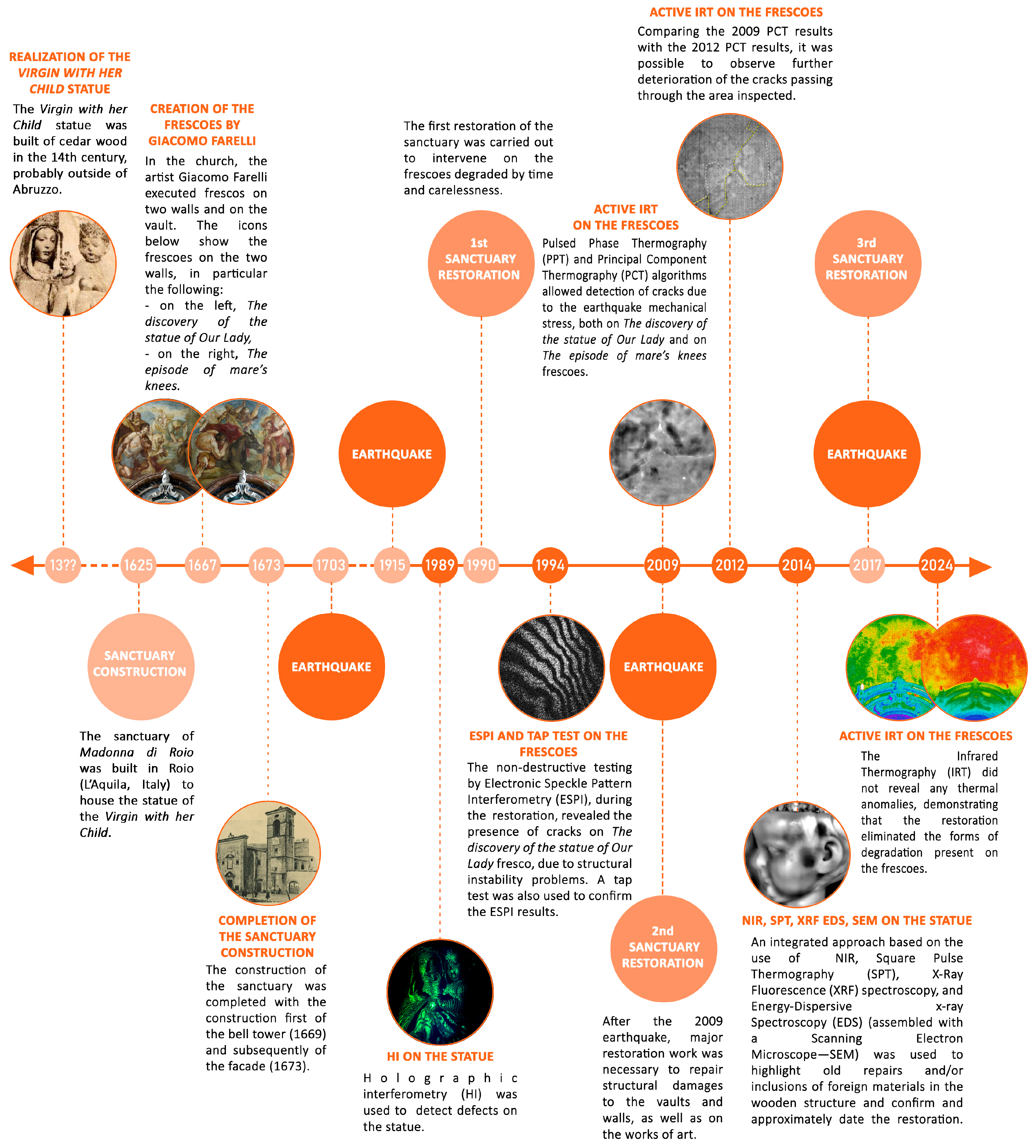
To provide a comprehensive overview of the present study, Figure 5 shows an infographic timeline of key events in the history of Santa Maria della Croce. This includes major restoration campaigns and main diagnostic investigations conducted over the past thirty-five years.
By integrating historical milestones, structural interventions, and scientific analyses, this timeline offers a clear visual representation of how the sanctuary has been studied and preserved over time. Each entry is positioned chronologically to highlight the interplay between conservation needs and diagnostic responses. This visual synthesis enables readers to understand the continuity and progression of the efforts to safeguard the site’s architectural and material integrity.
In the following, we present a selection of experimental results that emphasise important diagnostic findings and their significance for the conservation of the church.

3.1. The Façade

Such a long diagnostic project also inevitably provides an opportunity to study technological evolution.
In addition to the shift from pioneering, self-built equipment to commercially available devices, which was discussed in relation to Figure 4, the latter have also evolved remarkably. In particular, Figure 6 illustrates the technological evolution of thermal cameras throughout the course of this project.
Figure 6 shows the thermograms of the façade, which are a mosaic of thermographic images, taken with different instruments. The main characteristics of these instruments are summarised in Table 1.
As can be seen, we have moved from bulky, difficult-to-transport instruments to much more manageable thermal cameras that offer high-resolution images in just over 30 years. Improvements in portability have been fundamental in promoting the spread of in situ thermographic diagnostics, which has led to significant advancements in the field.
We will show in more detail below how dramatic improvements have also been made in image processing software.
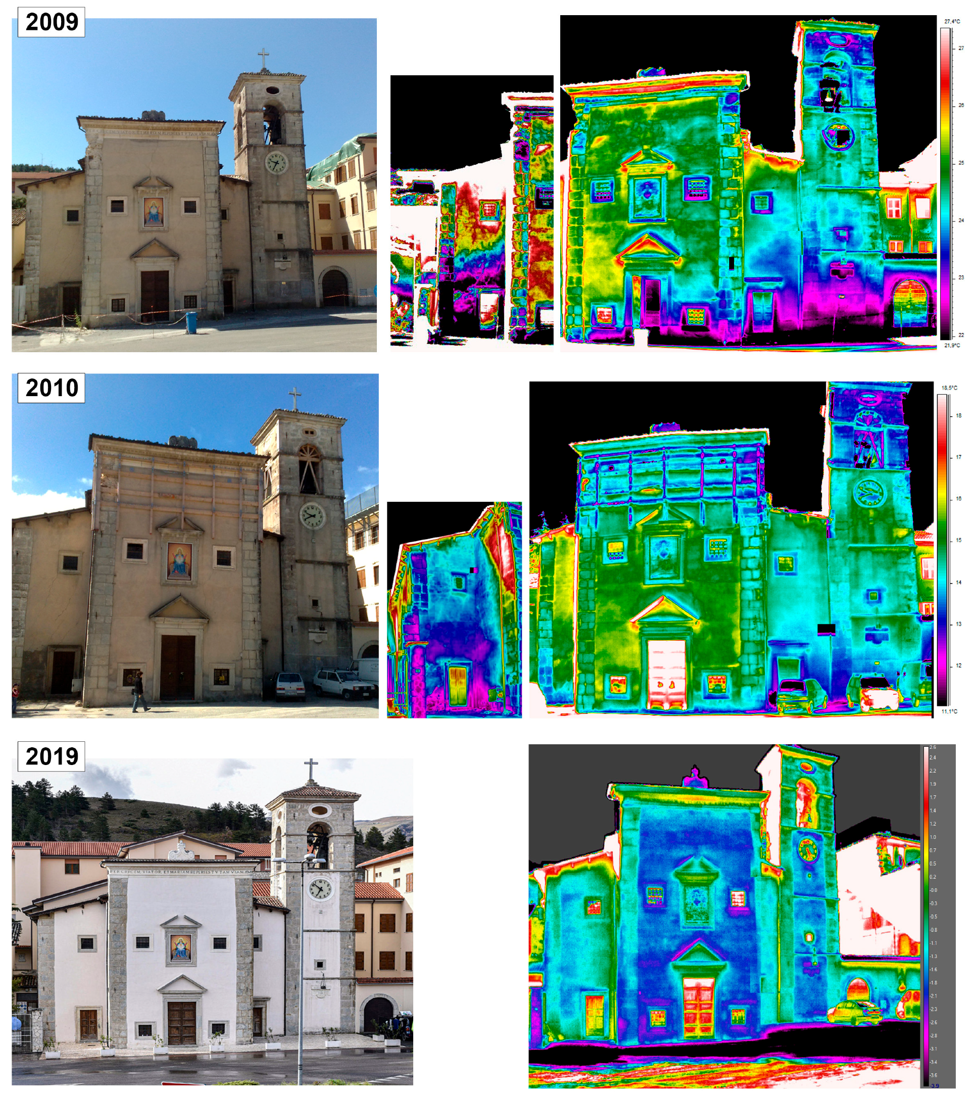
To gain more insight into the experimental results, see Figure 7. This image shows composite thermograms of the façade taken over a period of approximately 11 years, including the year of the 2009 earthquake. All thermograms were captured using a FLIR S65 HS thermal imaging camera.
The images from 2009 were captured approximately three months after the April earthquake, at a time when the structural damage to the church had not yet been stabilised. In the 2010 documentation, temporary safety scaffolding is clearly visible at the top of the façade and in the windows of the bell tower. By 2019, the images reflect the outcome of the restoration process, showing the church in its rehabilitated state. The testing was intentionally carried out in different climatic conditions to achieve different excitations.
In the thermograms from 2009 and 2010, cracks induced by the earthquake can be identified, as well as evidence of humidity and some detachment. Most of these defects were no longer present after the repair work.
A visual guide to help identify defects based on thermal anomalies is provided in Figure 8. The image on the left is from Figure 7 (2009). On the right, some cracks are highlighted (white lines) as well as areas of detachment, circled in white. In the lower area, colder regions are probably due to rising damp. Detachments usually appear hotter than the surrounding regions because the subtle air layer under the surface acts as a thermal resistance. While cracks could also be detected by the eye and/or a high-resolution photograph, this is not true for detachments and humidity. Furthermore, thermography can be very useful in cases where cracks extend beneath the surface and are difficult to detect visually.
In general, a thermographic survey of façades can provide information on cracks, detachments, moisture, and material heterogeneity. In some cases, it can also indicate the probable location of damage caused by a potential earthquake [50].

3.2. The Virgin with Her Child Statue

The first diagnostic examination of the statue by HI took place around 1989, specifically to test holographic techniques. Following the 2009 earthquake, a comprehensive diagnostic study incorporating active thermography (primarily SPT, or square pulse thermography), IRR, and XRF was planned. The results of these investigations, compared with previous HI diagnostics, were presented in [27].
The diagnostic project enabled several anomalies to be detected, such as splittings, cracks, craquelure, retouchings, and inclusions of foreign materials. The following provides a brief overview of the main results obtained using full-field techniques; interested readers are referred to the original publication [27] for more details.
Figure 9 shows an interferogram of the statue obtained using sandwich holography, a technique notable for its ease of manipulating the fringe pattern [5,6]. The form of the fringes can provide information about the type and extent of defects [5,31]. A vertical crack, indicated by the discontinuity of the fringes, is clearly visible on the Virgin’s forehead.
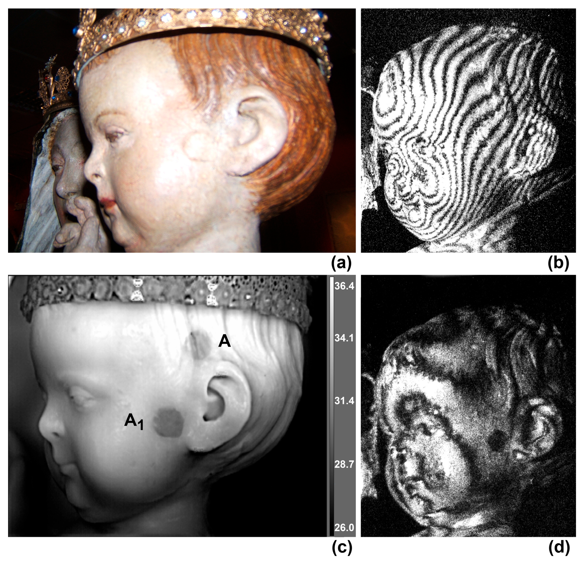
Figure 10a shows a photograph of the child’s head in the visible range. The experimental results obtained using HI and IRT are also presented in the same figure. These images can be fruitfully compared with Figure 7 from ref. [27], which reports the same interferograms together with an IRR result and an IRT measurement processed by a different method.
Thermograms were taken with the thermal camera at about 46 cm from the child’s head. Two halogen lamps (Osram Siccatherm—250 W IR) were positioned about 24 cm from the statue. The heating time was 180 s and the room temperature was 26.2 °C [27]. Of the two defects, A and A1 (interpreted as foreign material inclusions in [27]), only A1 is somewhat visible to the naked eye. The two defects are identified by distortion of the fringe pattern in the interferograms. Sandwich HI, with its ability to manipulate the fringe pattern [5], is particularly effective in detecting defect A1; see Figure 10d. Finally, Figure 10c shows a thermogram processed using the DDE (Digital Detail Enhancement) FLIR proprietary algorithm, available in FLIR ResearchIR Max software (version 4.40.12.38, March 2022). The two defects are clearly detected by IRT.
Figure 10c was obtained by reprocessing the raw thermographic data used in [27]. This image compares well with Figure 7c in [27], which was a PPT [51] phasegram f = 0.0017 Hz, obtained by dedicated algorithms. This comparison clearly illustrates the dramatic evolution of image processing software.

3.3. Farelli’s Frescoes on the Walls

The first diagnostic examination of Farelli’s frescoes on the walls began in the early 1990s, specifically to test the ESPI technique [52]. Following the 2009 earthquake, comprehensive diagnostics, including IRT and IRR, were planned. The results of these investigations, compared with previous ESPI diagnostics, were presented in [53].
Figure 4 (left) shows the ESPI prototype in action in the church.
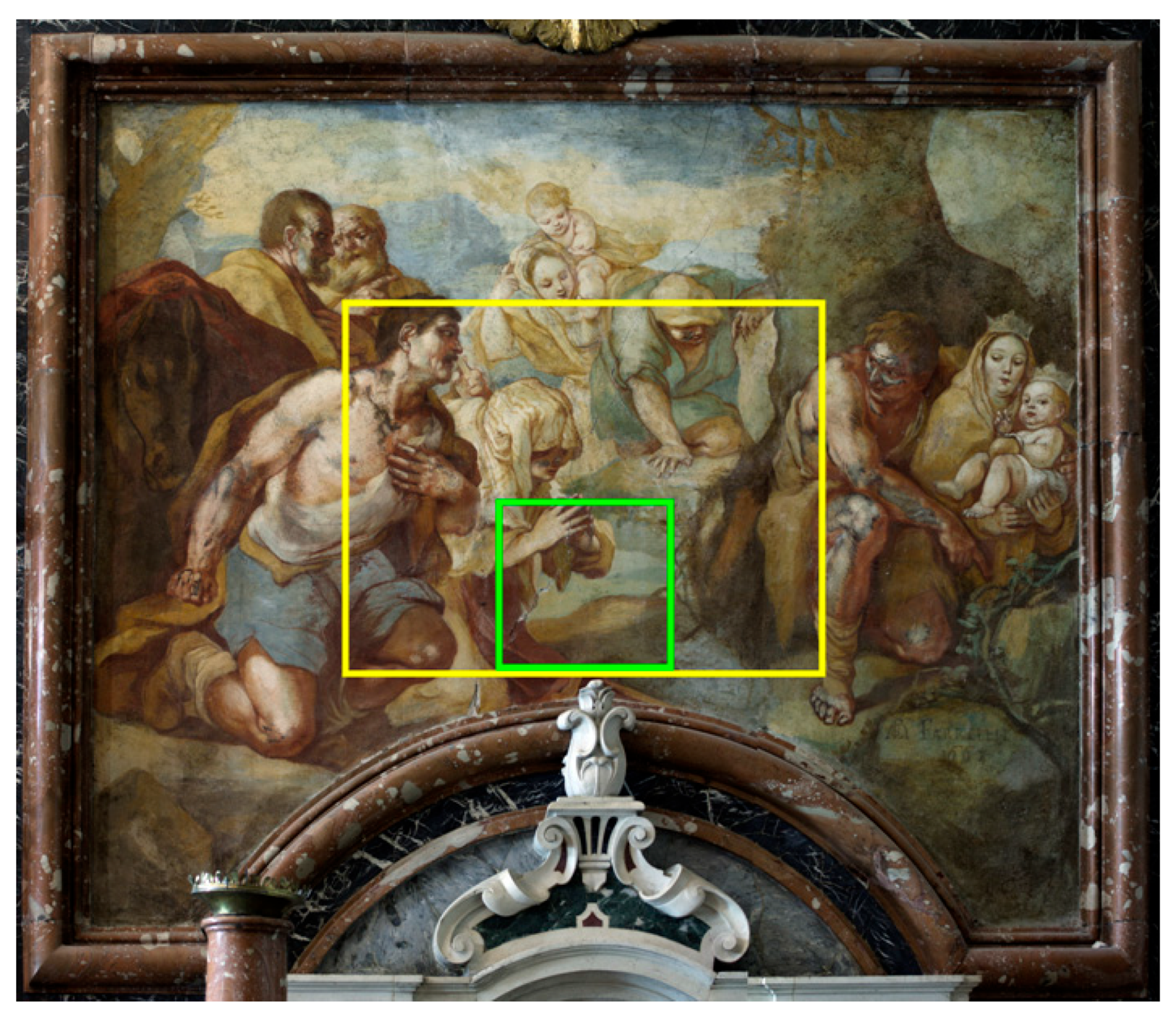
Figure 11 shows the areas investigated by ESPI (marked in green) and IRT (marked in yellow).
The restoration of the frescoes in the early 1990s provided an opportunity to test the ESPI diagnostics before and after the restoration work.
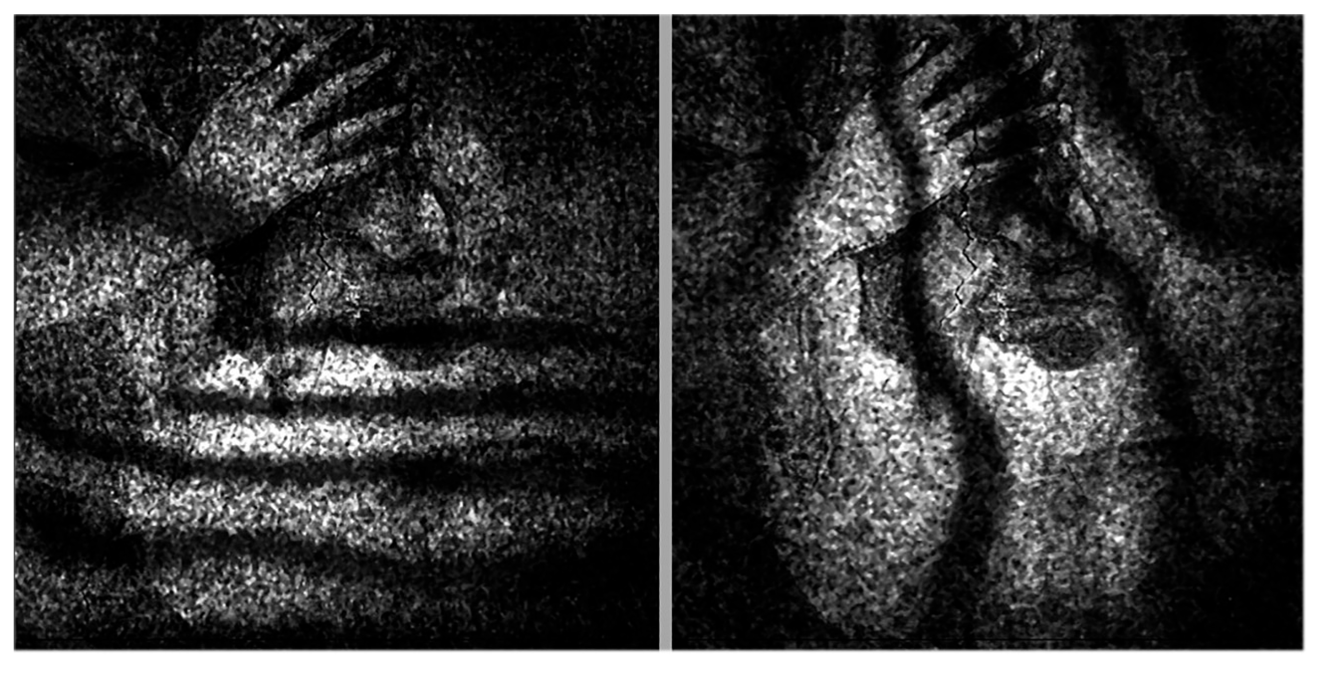
Figure 12 shows the relative deformation of the investigated area (see Figure 11) when subjected to brief thermal irradiation using a 150 W infrared lamp, at a distance of approximately 1 meter, before (left) and after (right) the restorations.
The left image shows abrupt deviations in the fringe pattern. These discontinuities are caused by cracks. After consolidating the damaged area, the region was analysed again under similar stress conditions and no anomalies were observed (see right-hand image).
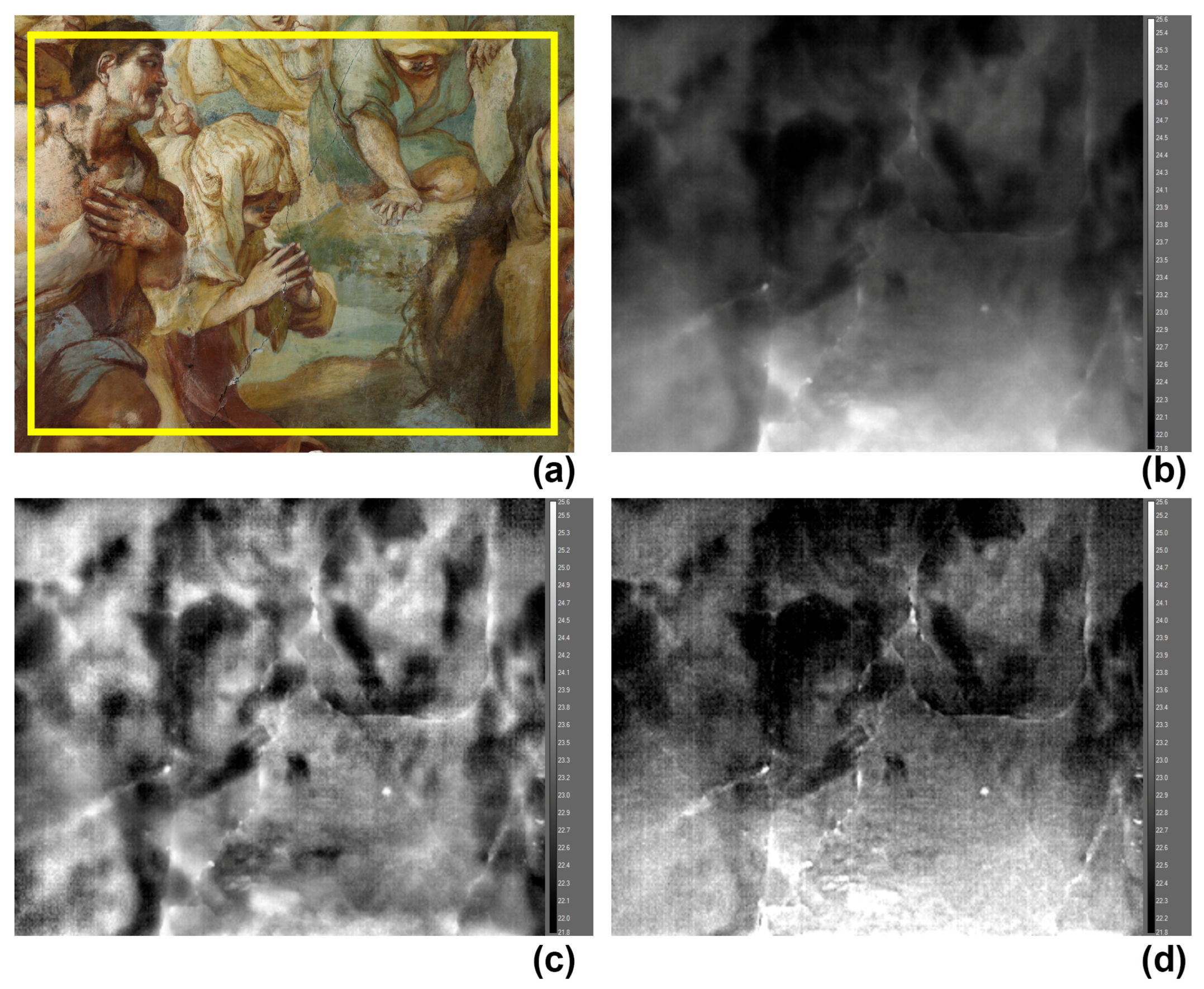
These diagnostics were repeated after the earthquake in 2009. During these measurement campaigns, we used IRT due to its great portability, speed, and ability to capture large areas. The raw thermographic data, recorded with a FLIR S65 HS thermal camera, have been specifically reprocessed for this study and should be compared with the results obtained by dedicated software in [53].
Figure 13 shows the results obtained using IRT. All images were processed via off-the-shelf algorithms in FLIR ResearchIR Max software (version 4.40.12.38, March 2022). In particular, Figure 13b was obtained using Plateau Equalisation (PE), Figure 13c with Advanced Plateau Equalisation (APE), and Figure 13d with Digital Detail Enhancement (DDE). PE is a histogram-based algorithm that provides good contrast for almost all images. APE runs in addition to PE and enhances image detail. DDE helps to locate low-contrast targets within scenes with a high dynamic range.
From these images, we can conclude that cracks which were repaired in the early 1990s reappeared because of the earthquake.
One final statement is worth adding. As emphasised previously, the results obtained in this study using off-the-shelf FLIR algorithms are in good agreement with those provided by dedicated algorithms. In ref. [53], PPT [51] and PCT [54] were used, and these nevertheless maintain their superiority in terms of their ability to provide information at different depths.

3.4. Farelli’s Fresco on the Vault

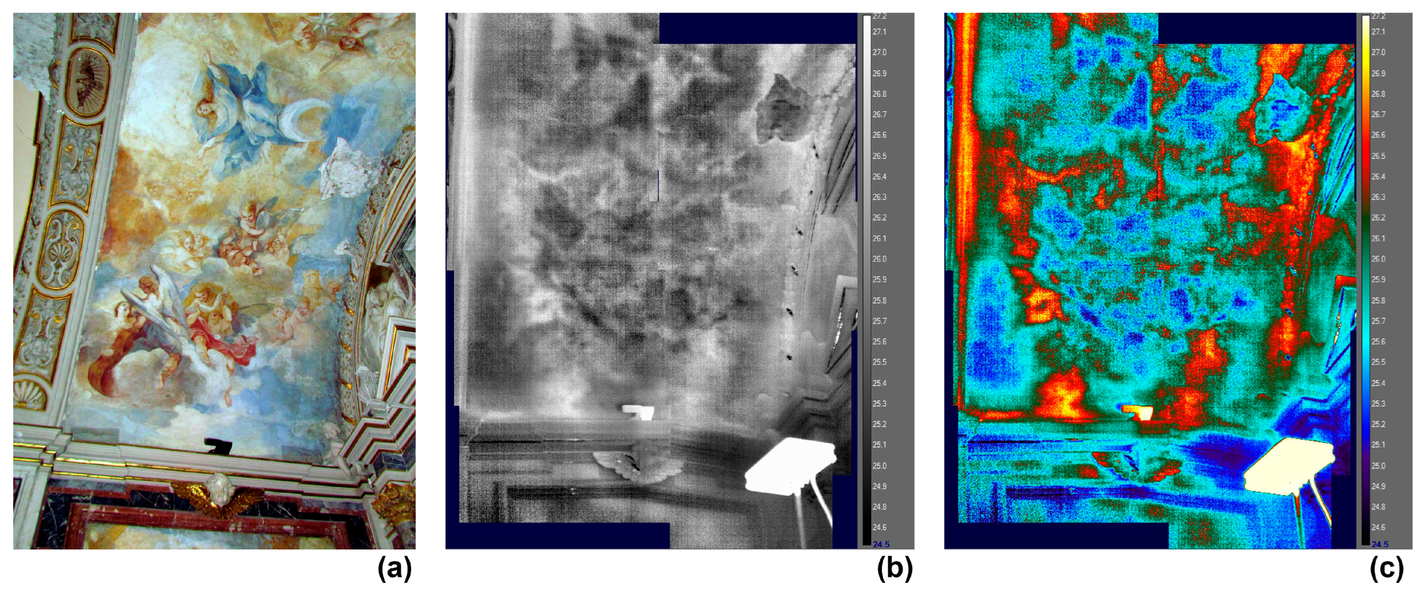
Figure 14 and Figure 15 show some results on Farelli’s fresco on the vault, representing the Assumption of the Virgin Mary. Thermographic data have been recorded during the 2011–2012 measurement campaign, before the restoration, using a FLIR S65 HS thermal camera. The thermograms have been processed by FLIR ResearchIR Max software (version 4.40.12.38, March 2022).
Figure 14a shows the fresco in the visible range. Note the significant loss of paint under the Virgin’s feet.
A composite thermogram has been processed by the DDE FLIR proprietary algorithm and is given in Figure 14b; the same thermogram has been visualised using the 1234 palette and is shown in Figure 14c.
Figure 14b clearly shows the cracks and inhomogeneities in the mural support. Figure 14c uses a different palette to highlight the detached areas (identified by the red and yellow areas).
Figure 15 shows a close-up of Farelli’s fresco on the vault. The damage caused by the earthquake is clearly visible; see Figure 15a.
Figure 15b shows a thermogram processed using the APE algorithm, revealing the inhomogeneities of the masonry and extensive cracking.
Figure 15c displays the thermogram from Figure 15b using the 1234 palette. It reveals how the extensive cracking has led to large areas of paint detaching; the air layer under the surface acts as a thermal barrier, reducing heat transfer and resulting in localised heating. Thus, detachments usually appear as the hottest areas.

3.5. Avicola’s Fresco

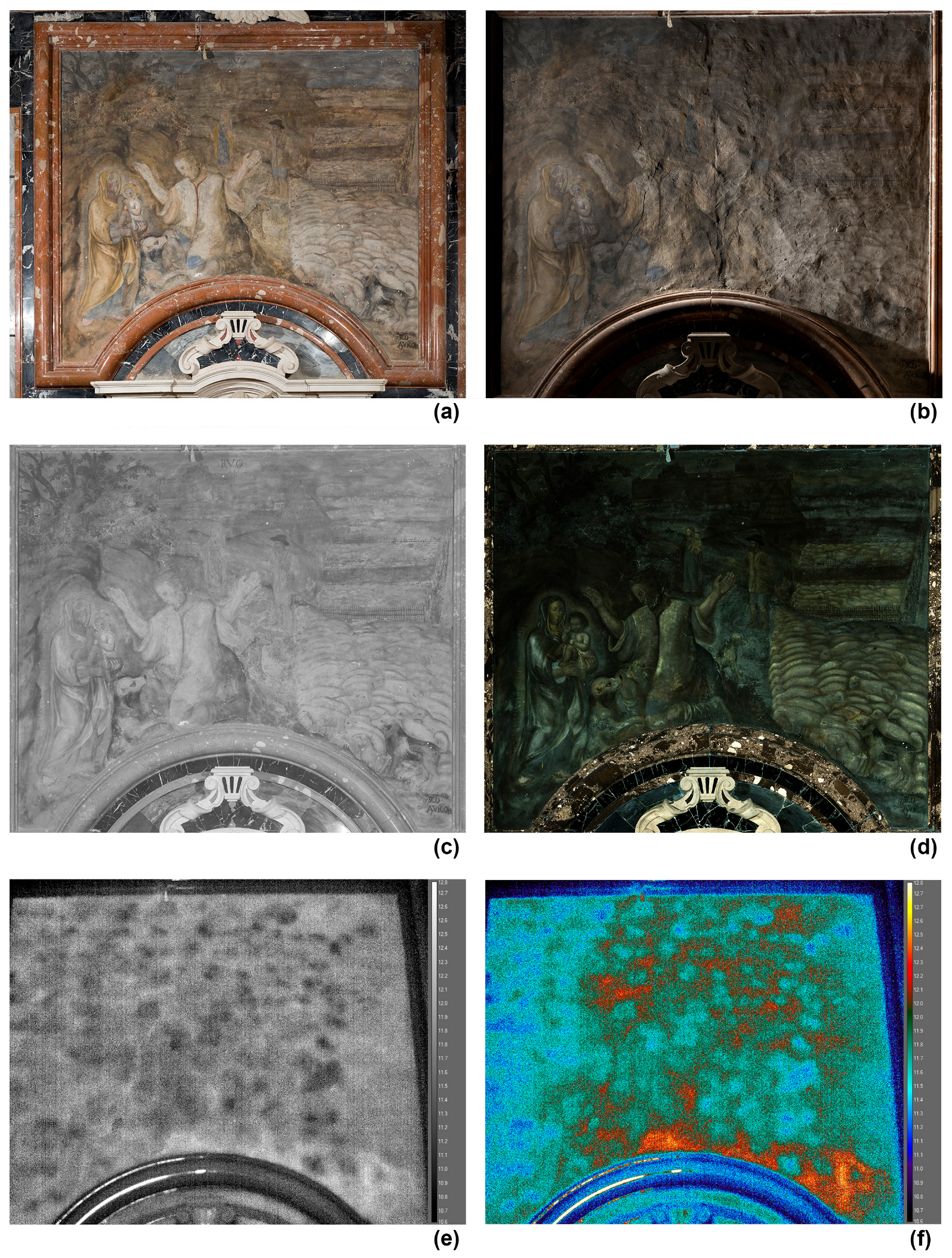
The fresco executed by Francesco Avicola in the second half of the 17th century was investigated using IRT, IRR, and special photographic techniques. Some of the results are shown in Figure 16. The thermographic data were recorded using a FLIR S65 HS thermal camera and processed using FLIR ResearchIR Max software (version 4.40.12.38, March 2022). The IRR, RAK, and UVF images were recorded using a modified Nikon D800 digital camera (full frame, 36.3 Mpx), coupled to suitable filters and capable of enhanced imaging over the full range of 350–1000 nm.
Figure 16a shows a visible image of the mural painting, which is signed in the bottom right-hand corner but not dated. Figure 16b shows a photograph taken with raking light and highlights surface deformations and a joint line approximately in the centre of the wall, suggesting that the painting was executed on different days (the so-called giornata); this is typical of buon fresco execution, in which the painting is realised on a layer of wet, fresh plaster; when the plaster dries, the painting becomes integral with the wall. Figure 16c,d show infrared reflectography (IRR) and ultraviolet fluorescence (UVF) images, respectively. The latter, in particular, evaluated by a restorer, provides information on the pigments, such as ochre and natural earths used for the yellows, and the absence of azurite and Prussian blue. Figure 16e,f show thermograms processed using the FLIR APE algorithm in two different colour palettes. Figure 16e clearly reveals the inhomogeneity of the mural support, as well as some cracks to the left of the centre line. The warmer areas in Figure 16f may indicate possible detachments.

3.6. The Ancient Virgin with Child Mural Painting

On the left as one enters the sanctuary, there is a small (0.35 m × 0.41 m) mural painting, which is all that remains of the pictorial decoration of the old chapel dedicated to St. Leonard from the 13th century.
This work is particularly important as it has recently been attributed to the so-called Maestro del Crocifisso d’argento (Master of the silver Crucifix), active in the first half of the 14th century, providing physical evidence of this artist’s presence in Abruzzo [55].
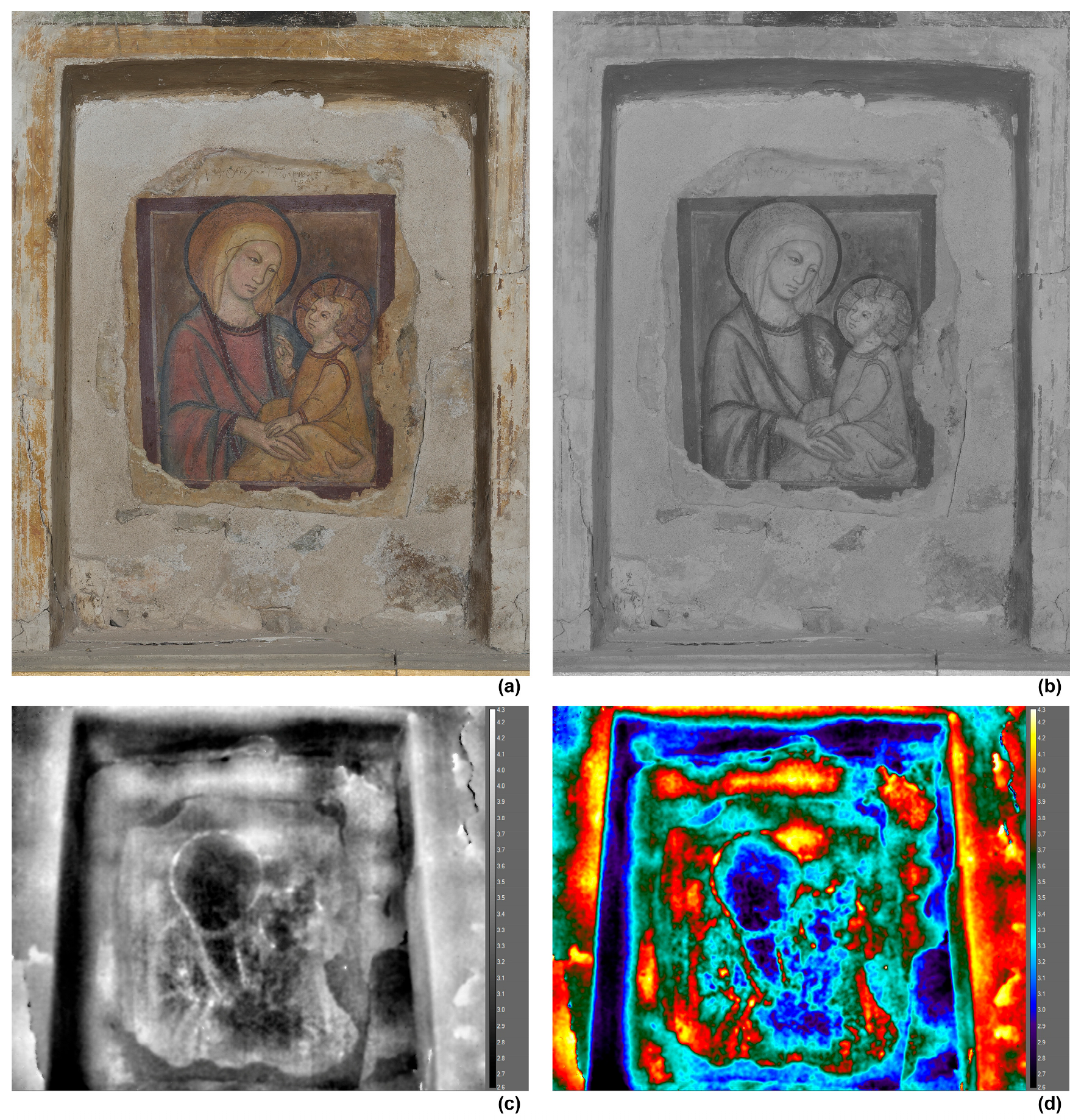
The painting was investigated using IRT, IRR, and special photographic techniques. The thermographic data were recorded using a FLIR T1030sc thermal camera and processed using FLIR ResearchIR Max software (version 4.40.12.38, March 2022).
Figure 17a,b, which were taken using a modified Nikon D800 digital camera, show the painting in the visible and near-infrared ranges. Figure 16b reveals a potential pentimento on the Virgin’s right hand. The thermograms, Figure 17c,d, reveal some warmer areas. These may represent possible detachments.

4. Conclusions

Findings from over thirty years of non-destructive diagnostic investigations of the Santa Maria della Croce church in Roio (L’Aquila, Italy) highlight the importance of continuous, integrated monitoring for preserving historic and artistic heritage. Long-term analysis enabled precise assessment of the evolving conservation state of the church and its artworks, revealing the variable effectiveness of restoration interventions and the significant impact of seismic events. This project combined established and advanced diagnostic techniques and provided a layered, multidimensional understanding of emerging vulnerabilities, highlighting the need for adaptive, responsive conservation strategies. The infographic shown in Figure 5 can serve as both a comprehensive overview and a resumé of the present study.
This study shows that integrated diagnostic approaches allow us to evaluate the effects of time and external stressors retrospectively, and also serve as essential predictive tools to guide future preservation policies.
Finally, this diagnostic study has yielded a rich dataset offering important insights. While replicating such a long-term model across many cultural assets is challenging due to financial and logistical constraints, structured collaboration between conservation authorities and academic institutions could make it feasible. Transforming cultural heritage sites into living labs—spaces for research, education, and experimentation—would enable this approach to be scaled up, facilitating the strategic long-term monitoring of cultural heritage on a wider scale.

Author Contributions

Conceptualisation, D.A. and D.P.; methodology, G.P. and A.M.; software, G.P., A.C. and A.M.; validation, C.D.L., T.d.R. and A.C.; formal analysis, C.D.L.; investigation, G.P., A.C. and A.M.; resources, D.P. and A.M.; data curation, C.D.L.; writing—original draft preparation, D.A., T.d.R. and A.C.; writing—review and editing, D.A. and D.P.; visualisation, A.C., A.M. and G.P.; supervision, D.P. and D.A.; project administration, D.P.; funding acquisition, D.P. and A.M. All authors have read and agreed to the published version of the manuscript.

Funding

This research received no external funding. Details about the funding of the previous research can be found in the related papers listed in the References section.

Data Availability Statement

Parts of the data presented in this study will be made available on reasonable request to the authors.

Acknowledgments

Research spanning more than 30 years involves many acknowledgements. First of all, thanks are due to the teachers, students, technicians, and experts who collaborated with the Las.E.R. laboratory. Special thanks are due to art historian Biancamaria Colasacco and architect Augusto Ciciotti for their continuous encouragement and guidance, and to the restorer Jenny Rolo for the great collaboration.

Conflicts of Interest

Author Antonio Mignemi is employed by MIMARC Srl. The authors declare no conflict of interest.

Abbreviations

The following abbreviations are used in this manuscript:
ESPIElectronic Speckle Pattern Interferometry
DSPIDigital Speckle Pattern Interferometry
HIHolographic Interferometry
IRRInfrared Reflectography
IRTInfrared Thermography
NDTNon-Destructive Testing
PCTPrincipal Component Thermography
PPTPulse Phase Thermography
RAKRAKing light photography
SPTSquare Pulse Thermography
UVFUltraviolet Photography
XRFX-Ray Fluorescence

References

  1. UNESCO. World Heritage. Available online: https://whc.unesco.org/en/about (accessed on 2 March 2025).
  2. UNESCO; ICCROM; ICOMOS and IUCN. Managing Cultural World Heritage; UNESCO: Paris, France, 2013; ISBN 9789230012236. Available online: https://whc.unesco.org/en/managing-cultural-world-heritage (accessed on 2 March 2025).
  3. Alfeld, M.; Broekaert, J.A.C. Mobile Depth Profiling and Sub-Surface Imaging Techniques for Historical Paintings—A Review. Spectrochim. Acta Part B At. Spectrosc. 2013, 88, 211–230. [Google Scholar] [CrossRef]
  4. Borg, B.; Dunn, M.; Ang, A.; Villis, C. The Application of State-of-the-Art Technologies to Support Artwork Conservation: Literature Review. J. Cult. Herit. 2020, 44, 239–259. [Google Scholar] [CrossRef]
  5. Paoletti, D.; Schirripa Spagnolo, G. Interferometric methods for artwork diagnostics. In Progress in Optics; Wolf, E., Ed.; Elsevier: Amsterdam, The Netherlands, 1996; Volume 35, pp. 197–255. [Google Scholar] [CrossRef]
  6. Ambrosini, D.; Paoletti, D. Holographic and Speckle Methods for the Analysis of Panel Paintings. Developments since the Early 1970s. Stud. Conserv. 2004, 49, 38–48. [Google Scholar] [CrossRef]
  7. Tornari, V.; Tsiranidou, E.; Bernikola, E. Interference Fringe-Patterns Association to Defect-Types in Artwork Conservation: An Experiment and Research Validation Review. Appl. Phys. A 2012, 106, 397–410. [Google Scholar] [CrossRef]
  8. Daffara, C.; Marini, E. A Portable Compact System for Laser Speckle Correlation Imaging of Artworks Using Projected Speckle Pattern. J. Imaging 2020, 6, 119. [Google Scholar] [CrossRef]
  9. Zhu, Y.; Chen, Z.; Zhou, W.; Yu, Y.; Tornari, V. Photoacoustic Speckle Pattern Interferometry for Detecting Cracks of Different Sizes. Opt. Express 2023, 31, 40328. [Google Scholar] [CrossRef]
  10. Tao, N.; Van Duijn, E.; Vos, L.; Steeman, I.; Groves, R.M.; Keune, K.; Noble, P.; Anisimov, A.G. Assessing the Structural Integrity of the Wax-Resin Lining of The Night Watch Using 3D Shearography. J. Cult. Herit. 2025, 72, 169–179. [Google Scholar] [CrossRef]
  11. Ibarra-Castanedo, C.; Sfarra, S.; Ambrosini, D.; Paoletti, D.; Bendada, A.; Maldague, X. Diagnostics of Panel Paintings Using Holographic Interferometry and Pulsed Thermography. Quant. InfraRed Thermogr. J. 2010, 7, 85–114. [Google Scholar] [CrossRef]
  12. Gavrilov, D.; Maev, R.G.; Almond, D.P. A Review of Imaging Methods in Analysis of Works of Art: Thermographic Imaging Method in Art Analysis. Can. J. Phys. 2014, 92, 341–364. [Google Scholar] [CrossRef]
  13. Mercuri, F.; Cicero, C.; Orazi, N.; Paoloni, S.; Marinelli, M.; Zammit, U. Infrared Thermography Applied to the Study of Cultural Heritage. Int. J. Thermophys. 2015, 36, 1189–1194. [Google Scholar] [CrossRef]
  14. Moropoulou, A.; Avdelidis, N.; Karoglou, M.; Delegou, E.; Alexakis, E.; Keramidas, V. Multispectral Applications of Infrared Thermography in the Diagnosis and Protection of Built Cultural Heritage. Appl. Sci. 2018, 8, 284. [Google Scholar] [CrossRef]
  15. Dritsa, V.; Orazi, N.; Yao, Y.; Paoloni, S.; Koui, M.; Sfarra, S. Thermographic Imaging in Cultural Heritage: A Short Review. Sensors 2022, 22, 9076. [Google Scholar] [CrossRef] [PubMed]
  16. Sutherland, N.; Marsh, S.; Priestnall, G.; Bryan, P.; Mills, J. InfraRed Thermography and 3D-Data Fusion for Architectural Heritage: A Scoping Review. Remote Sens. 2023, 15, 2422. [Google Scholar] [CrossRef]
  17. Targowski, P.; Iwanicka, M. Optical Coherence Tomography: Its Role in the Non-Invasive Structural Examination and Conservation of Cultural Heritage Objects—A Review. Appl. Phys. A 2012, 106, 265–277. [Google Scholar] [CrossRef]
  18. Cheung, C.S.; Spring, M.; Liang, H. Ultra-High Resolution Fourier Domain Optical Coherence Tomography for Old Master Paintings. Opt. Express 2015, 23, 10145. [Google Scholar] [CrossRef]
  19. Jackson, J.B.; Bowen, J.; Walker, G.; Labaune, J.; Mourou, G.; Menu, M.; Fukunaga, K. A Survey of Terahertz Applications in Cultural Heritage Conservation Science. IEEE Trans. Terahertz Sci. Technol. 2011, 1, 220–231. [Google Scholar] [CrossRef]
  20. Alfeld, M.; De Viguerie, L. Recent Developments in Spectroscopic Imaging Techniques for Historical Paintings—A Review. Spectrochim. Acta Part B At. Spectrosc. 2017, 136, 81–105. [Google Scholar] [CrossRef]
  21. Bergamo, O.; Campione, G.; Donadello, S.; Russo, G. In-situ NDT testing procedure as an integral part of failure analysis of historical masonry arch bridges. Eng. Fail. Anal. 2015, 57, 31–55. [Google Scholar] [CrossRef]
  22. Ibarra-Castanedo, C.; Sfarra, S.; Ambrosini, D.; Paoletti, D.; Bendada, A.; Maldague, X. Subsurface defect characterization in artworks by quantitative pulsed phase thermography and holographic interferometry. Quant. InfraRed Thermogr. J. 2008, 5, 131–149. [Google Scholar] [CrossRef]
  23. Chaban, A.; Tornari, V.; Deiana, R.; Andrianakis, M.; Giovannacci, D.; Detalle, V. A combined non-invasive approach to the study of a mosaic model: First laboratory experimental results. J. Imaging 2019, 5, 58. [Google Scholar] [CrossRef]
  24. Tornari, V.; Andrianakis, M.; Chaban, A.; Kosma, K. Heat transfer effects on defect boundaries captured by digital holographic interferometry and infrared thermography workstation: An overview on experimental results. Exp. Tech. 2020, 44, 59–74. [Google Scholar] [CrossRef]
  25. Özmen, A.; Sayin, E. Evaluation of material properties of cultural heritage building by destructive and non- destructive testing: Malatya Taşhoran Church case study. Constr. Build. Mater. 2023, 392, 131693. [Google Scholar] [CrossRef]
  26. L’Aquila—Saving an Art City; CARSA Edizioni: Pescara, Italy, 2009; ISBN 9788850101092.
  27. Sfarra, S.; Ibarra-Castanedo, C.; Ridolfi, S.; Cerichelli, G.; Ambrosini, D.; Paoletti, D.; Maldague, X. Holographic Interferometry (HI), Infrared Vision and X-Ray Fluorescence (XRF) Spectroscopy for the Assessment of Painted Wooden Statues: A New Integrated Approach. Appl. Phys. A 2014, 115, 1041–1056. [Google Scholar] [CrossRef]
  28. Giacomo Farelli. Available online: https://www.treccani.it/enciclopedia/giacomo-farelli_(Dizionario-Biografico)/ (accessed on 16 March 2025).
  29. Lattuada, R.; Raucci, L. Vita e Opere di Giacomo Farelli (1629–1706)—Artista e Gentiluomo nell’età Barocca; Tau editrice: Todi, Italy, 2020; ISBN 9788862449090. [Google Scholar]
  30. Locati, M.; Camassi, R.; Rovida, A.; Ercolani, E.; Bernardini, F.; Castelli, V.; Caracciolo, C.H.; Tertulliani, A.; Rossi, A.; Azzaro, R.; et al. Italian Macroseismic Database (DBMI15); Version 4.0 [Data Set]; Istituto Nazionale di Geofisica e Vulcanologia (INGV): Roma, Italy, 2022. [Google Scholar] [CrossRef]
  31. Vest, C.M. Holographic Interferometry; John Wiley & Sons: New York, NY, USA, 1979; ISBN 0471906832. [Google Scholar]
  32. Amadesi, S.; Gori, F.; Grella, R.; Guattari, G. Holographic methods for painting diagnostics. Appl. Opt. 1974, 13, 2009–2013. [Google Scholar] [CrossRef]
  33. Ambrosini, D.; Ciccozzi, A.; de Rubeis, T.; Paoletti, D. Unveiling the Art-Science Tapestry: Optical Methods in Cultural Heritage Conservation and Restoration. Img J. 2024, 10, 78–91. [Google Scholar] [CrossRef]
  34. Rastogi, P.K. (Ed.) Digital Speckle Pattern Interferometry and Related Techniques; John Wiley & Sons: Chichester, UK, 2001; ISBN 0471490520. [Google Scholar]
  35. Viotti, M.R. Digital Speckle Pattern Interferometry. In Digital Optical Measurement Techniques and Applications; Rastogi, P., Ed.; Artech House: Norwood, MA, USA, 2015; ISBN 9781608078066. [Google Scholar]
  36. Maldague, X.P.V. (Ed.) Nondestructive Testing Handbook: Vol. 4, Thermal and Infrared Testing, 4th ed.; ASNT: Columbus, OH, USA, 2024; ISBN 978157117488. [Google Scholar]
  37. Cascardi, A.; Longo, F.; Perrone, D.; Lassandro, P.; Aiello, M.A. Thermography Investigation and Seismic Vulnerability Assessment of a Historical Vaulted Masonry Building. Heritage 2022, 5, 2041–2061. [Google Scholar] [CrossRef]
  38. Grinzato, E.; Bressan, C.; Marinetti, S.; Bison, P.G.; Bonacina, C. Monitoring of the Scrovegni Chapel by IR Thermography: Giotto at infrared. Infrared Phys. Technol. 2002, 43, 165–169. [Google Scholar] [CrossRef]
  39. Theodorakeas, P.; Ibarra-Castanedo, C.; Sfarra, S.; Avdelidis, N.P.; Koui, M.; Maldague, X.; Paoletti, D.; Ambrosini, D. NDT inspection of plastered mosaics by means of transient thermography and holographic interferometry. NDT E Int. 2012, 47, 150–156. [Google Scholar] [CrossRef]
  40. Martorana, R.; Capizzi, P. Joint Investigation with Ground Penetrating Radar and Infrared Thermography as a Diagnostic Support for the Restoration of Two Wall Mosaics in the Church of St. Mary of the Admiral in Palermo, Italy. Heritage 2022, 5, 2298–2314. [Google Scholar] [CrossRef]
  41. Saltarelli, C.; Di Meo, A.; Rippa, M.; Pagliarulo, V.; Cacace, T.; Paturzo, M. Multimodal Imaging for Wooden Panel Painting Analysis: Consegna della regola Francescana by Colantonio, a Case Study. Heritage 2025, 8, 118. [Google Scholar] [CrossRef]
  42. van Asperen de Boer, J.R.J. Infrared Reflectography: A Method for the Examination of Paintings. Appl. Opt. 1968, 7, 1711–1714. [Google Scholar] [CrossRef]
  43. Daffara, C.; Pampaloni, E.; Pezzati, L.; Barucci, M.; Fontana, R. Scanning multispectral IR reflectography SMIRR: An advanced tool for art diagnostics. Acc. Chem. Res. 2010, 43, 847–856. [Google Scholar] [CrossRef]
  44. Ambrosini, D.; Daffara, C.; Di Biase, R.; Paoletti, D.; Pezzati, L.; Bellucci, R.; Bettini, F. Integrated reflectography and thermography for wooden paintings diagnostics. J. Cult. Herit. 2010, 11, 196–202. [Google Scholar] [CrossRef]
  45. Moreno-Soto, J.; Križnar, A.; Ager, F.J.; Gómez, A.; Gamero-Osuna, A.; Martín-de-Soto, A.; Respaldiza, M.Á. Material and Imaging Analysis Procedure for the Investigation of Paintings in the Archbishop’s Palace of Seville. Heritage 2023, 6, 4527–4541. [Google Scholar] [CrossRef]
  46. Vasco, G.; Aureli, H.; Fernández-Lizaranzu, I.; Moreno-Soto, J.; Križnar, A.; Parrilla-Giraldez, R.; Gómez-González, E.; Respaldiza Galisteo, M.A. Development of a Hyperspectral Imaging Protocol for Painting Applications at the University of Seville. Heritage 2024, 7, 5986–6007. [Google Scholar] [CrossRef]
  47. Townsend, J.H. Technical Examination and Imaging. Grove Art Online 2022. [Google Scholar] [CrossRef]
  48. Lanteri, L.; Calandra, S.; Briani, F.; Germinario, C.; Izzo, F.; Pagano, S.; Pelosi, C.; Santo, A.P. 3D Photogrammetric Survey, Raking Light Photography and Mapping of Degradation Phenomena of the Early Renaissance Wall Paintings by Saturnino Gatti—Case Study of the St. Panfilo Church in Tornimparte (L’Aquila, Italy). Appl. Sci. 2023, 13, 5689. [Google Scholar] [CrossRef]
  49. Davies, A. Digital Ultraviolet and Infrared Photography; Routledge: New York, NY, USA, 2017; ISBN 9781138200173. [Google Scholar]
  50. Paoletti, D.; Ambrosini, D.; Sfarra, S.; Bisegna, F. Preventive thermographic diagnosis of historical buildings for consolidation. J. Cult. Herit. 2013, 14, 116–121. [Google Scholar] [CrossRef]
  51. Maldague, X.; Marinetti, S. Pulse phase thermography. J. Appl. Phys. 1996, 79, 2694–2698. [Google Scholar] [CrossRef]
  52. Paoletti, D.; Schirripa Spagnolo, G. Application of fibre optic digital speckle interferometry to mural painting diagnostics. Meas. Sci. Technol. 1993, 4, 614–618. [Google Scholar] [CrossRef]
  53. Sfarra, S.; Ibarra-Castanedo, C.; Ambrosini, D.; Paoletti, D.; Bendada, A.; Maldague, X. Non-Destructive Testing Techniques to Help the Restoration of Frescoes. Arab. J. Sci. Eng. 2014, 39, 3461–3480. [Google Scholar] [CrossRef]
  54. Rajic, N. Principal component thermography for flaw contrast enhancement and flaw depth characterization in composite structures. Compos. Struct. 2002, 58, 521–528. [Google Scholar] [CrossRef]
  55. Paqualetti, C. Pittori di confine. Nuove ricerche e scoperte sui trecentisti ‘umbri’ in Abruzzo. Paragone 2020, 149, 3–20. [Google Scholar]
Figure 1. (Left) The sanctuary of Madonna di Roio in an image taken between the end of the 19th century and the beginning of the 20th century. (Centre) Schematic floor plan. (Right) A recent image (March 2025) of the sanctuary.
Heritage 08 00446 g001
Figure 2. The Virgin with her Child statue (14th century). The 1667 artistic representation by Farelli is probably one of the oldest images of the statue.
Heritage 08 00446 g002
Figure 3. Fresco The discovery of the statue of Our Lady by Giacomo Farelli, signed and dated 1667 (lower right).
Heritage 08 00446 g003
Figure 4. Comparison of in situ diagnostic instrumentation used thirty years apart in the church.
Heritage 08 00446 g004
Figure 5. Timeline of key events, restorations, and diagnostic investigations at Santa Maria della Croce, with a focus on the last 35 years.
Heritage 08 00446 g005
Figure 6. Thermograms recorded with different thermal cameras: AVIO TVS−2000MkII (2003), outdoor temperature about 20 °C; FLIR S65 HS (2019), outdoor temperature about 2 °C; FLIR T1030sc (2025), outdoor temperature about 21 °C. All images were taken at about 25 m.
Heritage 08 00446 g006
Figure 7. Composite thermograms of the façade: 2009, outdoor temperature about 22 °C; 2010, outdoor temperature about 25 °C; 2019, outdoor temperature about 2 °C. All images were taken at about 25 m.
Heritage 08 00446 g007
Figure 8. Defect identification on the façade: main cracks (white lines), detachments (circled in white), and rising damp (colder areas near the ground).
Heritage 08 00446 g008
Figure 9. Interferogram, obtained by sandwich holography, on The Virgin with her Child statue. The vertical dimension is about 0.45 m.
Heritage 08 00446 g009
Figure 10. The Virgin with her Child (detail): (a) visible; (b) interferogram; (c) thermogram processed by the FLIR DDE algorithm; (d) interferogram with a different fringe pattern.
Heritage 08 00446 g010
Figure 11. One of the frescoes on the walls by Farelli, with the marked areas investigated by ESPI (green) and by IRT (yellow). The fresco dimensions are 2 m × 2.4 m, approximately.
Heritage 08 00446 g011
Figure 12. Images obtained by ESPI before (left) and after (right) repair work. The investigated area (approximately 0.3 m × 0.3 m) is the one marked in green in Figure 11.
Heritage 08 00446 g012
Figure 13. IRT results obtained by reprocessing raw data of June 2009: (a) investigated area; (b) thermogram processed by PE; (c) thermogram processed by APE; (d) thermogram processed by DDE. The investigated area is about 1.2 m × 0.9 m.
Heritage 08 00446 g013
Figure 14. Assumption of the Virgin by Francesco Farelli (around 1667). IRT results: (a) visible; (b) thermogram processed by APE; (c) same thermogram as in (b) visualised using the 1234 palette. The investigated area is about 3.3 m × 4 m.
Heritage 08 00446 g014
Figure 15. Assumption of the Virgin (detail) by Francesco Farelli (around 1667). IRT results: (a) visible; (b) thermogram processed by APE; (c) same thermogram as in (b) visualised using the 1234 palette.
Heritage 08 00446 g015
Figure 16. The Virgin Mary appearing to the shepherd Felice Calcagno by Francesco Avicola: (a) visible; (b) RAK; (c) IRR using a Filter IR pass at 850 nm; (d) UVF; (e) thermogram processed by APE; (f) same thermogram as in (e) visualised using the 1234 palette. The fresco dimensions are 2.4 m × 2.3 m, approximately.
Heritage 08 00446 g016
Figure 17. The Virgin with Child by the Maestro del Crocifisso d’argento (first half of the 14th century): (a) visible; (b) IRR using a Filter IR pass at 850 nm; (c) thermogram processed by APE; (d) same thermogram as in (c) visualised using the 1234 palette.
Heritage 08 00446 g017
Table 1. Technical characteristics of the thermal cameras used in this work. FLIR equipment is manufactured by Teledyne FLIR LLC, Wilsonville, OR, USA. Avio equipment is by Nippon Avionics Co., Ltd., Yokohama, Japan.
ModelYearResolutionTemperature RangeThermal Sensitivity/NETDDimensions/Weight
FLIR T1030sc
Heritage 08 00446 i001
20211024 × 768
UltraMax®
2048 × 1536
−40–2000 °C<20 mK @ 30 °C168(W) × 206(D) × 188(H) mm
2.0 kg
FLIR S65 HS
Heritage 08 00446 i002
2005320 × 240−40–1500 °C<50 mK100(W) × 250(D) × 190(H) mm
2.0 kg
AVIO TVS−2000MkII
Heritage 08 00446 i003
1995256 × 200−40–300 °C<100 mK @ 30 °CCamera Head:
185(W) × 300(D) × 181(H) mm
3.8 kg
Processor:
300(W) × 400(D) × 170(H) mm
9.0 kg
Disclaimer/Publisher’s Note: The statements, opinions and data contained in all publications are solely those of the individual author(s) and contributor(s) and not of MDPI and/or the editor(s). MDPI and/or the editor(s) disclaim responsibility for any injury to people or property resulting from any ideas, methods, instructions or products referred to in the content.