Article

Ultrasonic Study of Longitudinal Critically Refracted and Bulk Waves of the Heat-Affected Zone of a Low-Carbon Steel Welded Joint under Fatigue

by
Alexander Gonchar
*,
Alexander Solovyov
and
Vyacheslav Klyushnikov
Federal Research Center A.V. Gaponov-Grekhov Institute of Applied Physics of the Russian Academy of Sciences (IAP RAS), 46 Ul’yanov Street, 603950 Nizhny Novgorod, Russia
*
Author to whom correspondence should be addressed.
Acoustics 2024, 6(3), 593-609; https://doi.org/10.3390/acoustics6030032
Submission received: 9 April 2024 / Revised: 6 June 2024 / Accepted: 20 June 2024 / Published: 29 June 2024

Abstract

:
Currently, ultrasonic methods for assessing the fatigue lifetime of various structural materials are being actively developed. Many steel constructions are made by welding. The weld heat-affected zone is the weak point of the construction, as it is most susceptible to destruction. Therefore, it is actually important to search for acoustic parameters that uniquely characterize the structural damage accumulation in the heat-affected zone of a welded joint in order to predict failure. In this work, the specimens were made from the base metal and the welded joint’s heat-affected zone. The specimens were subjected to uniaxial tension–compression under a symmetrical cycle in the region of low-cycle fatigue with control of the strain amplitude. The propagation bulk velocities of longitudinal, shear waves and subsurface longitudinal critically refracted (LCR) waves during cyclic loading were studied. The acoustic birefringence of shear waves was calculated, and a similar parameter was proposed for longitudinal and LCR waves. The dependence of the elastic modulus ratio on the cycle ratio was obtained. It was shown that the acoustic parameters change most intensively in the heat-affected zone. According to the data of the C33/C55 ratio changes measured through the ultrasonic method, a formula for calculating the remaining fatigue life in the heat-affected zone was proposed.

1. Introduction

The fatigue of metal components is a common problem in the oil, gas, chemical, nuclear, aerospace, marine, hydropower, and building industries. For load-bearing elements of welded structures, hot-rolled, low-carbon steel is widely used in many industries due to its machinability, weldability, and mechanical properties. Welded joints are weakened areas due to the inhomogeneity of the materials’ microstructure and mechanical properties [1,2,3]. Furthermore, during welding, there is usually a heat-affected zone (HAZ). The HAZ is the weakest point, so material destruction most often occurs there [2,3].
Predicting the fatigue behavior of welded joints is a difficult problem. Theoretical approaches to the fatigue analysis of welded joints are complicated by many influencing factors [1]. Therefore, it is important to carry out in-service monitoring of the welded joint material state for timely maintenance and repair work in order to prevent failures and accidents in these constructions. To monitor the damage of components experiencing fatigue, including welded joints, nondestructive evaluation techniques can be used [4]. Ultrasonic testing is one of the most commonly used NDT methods [5,6].
The fatigue process usually consists of several stages: incubation, initiation, and, further, the development of microcracks, the emergence of a main crack, and the main crack’s growth into a final fracture. The early stages of fatigue are rarely monitored using nondestructive testing methods, in contrast to the stage of main crack growth. Meanwhile, the accumulation of microstructural damage begins immediately at the incubation stage [7,8,9] and can take up about 90% of the fatigue lifetime [8,9,10]. In this context, monitoring material degradation in the early stages of fatigue seems to be an exceedingly common engineering task. Ultrasonic nondestructive evaluation techniques have the ability to define the amount of damage through the monitoring of microstructure-sensitive parameters [10,11,12]. Due to their sensitivity to microstructures, ultrasonic techniques can be used to control the fatigue behavior of welded joints [13].
Surface and internal microstructural damage must be monitored separately, as they can accumulate at different rates.
For internal damage evaluation, it is advisable to use an ultrasonic method based on bulk wave propagation analysis [14,15,16,17]. The most promising techniques are those based on acoustic birefringence measurements and the elastic modulus ratio. These techniques have an important advantage: there is no need to measure the thickness of the material since relative values are determined by measuring the ultrasonic waves’ propagation times through the material thickness.
To determine the characteristics of the microstructure in the near-surface layer and to evaluate stresses, LCR waves are often used [18,19,20]. Waves of this type propagate in the subsurface layer at a velocity close to the velocity of a longitudinal wave. LCR waves (also called lateral or creeping waves in NDT) radiate a bulk shear wave into the material at an angle of under 33°, approximately, which leads to a strong attenuation [21,22,23]. Head waves are widely used in TOFD [24,25].
They are not sensitive to the state of the surface, and the depth of penetration can be changed using different wave frequencies. There are two primary aims of this study. The first aim is to investigate the effect of fatigue on the bulk and LCR waves’ velocities in the heat-affected zone and the base metal of the low-carbon steel welded joint. The second aim is to investigate changes in nondimensional parameters, defined as the ratio of velocities or time propagation, to determine the most sensitive of them to the evolution of the microstructure during fatigue. Understanding how acoustic parameters change in the different zones of a welded joint under fatigue can be utilized in structural health-monitoring applications based on ultrasonic techniques.

2. Theoretical Background

2.1. Bulk Waves

The bulk elastic wave velocities propagating through a polycrystalline material are related to its elastic properties and can be determined by the Christoffel eigenvalues equation [26]:
C i j k l n ^ j n ^ k ρ v 2 δ i l u i = 0 ,
where n ^ is the unit vector normal to the wavefront, indicating, therefore, the direction of propagation of the wave, ρ is the density of the medium, v is the phase velocity, C i j k l represents the second-order elastic constants, u is the displacement or polarization vector, and δil is the Kronecker delta.
Equation (1) corresponds to three homogeneous equations, the solution of which results in three different velocity values for each considered wave propagation direction by taking the determinant of the coefficient matrix equal to zero. These values correspond to the phase velocities of three ultrasonic waves with mutually perpendicular polarization vectors. The following relations are obtained for an anisotropic material:
C 33 = ρ V 33 2 ,           C 44 = ρ V 32 2 ,           C 55 = ρ V 31 2 ,
where V 33   is the longitudinal wave velocity and V 32 and V 31 are the shear wave velocities; the first index shows the wave propagation direction, and the second index indicates the direction of polarization.
The difference between the elastic constants C44 and C55 gives rise to the acoustic birefringence:
B = 2 t 32 t 31 t 31 + t 32 = 2 V 31 V 32 V 32 + V 31 ,
where t31 and t32 are the time propagations of shear waves (the first index corresponds to the direction of propagation, and the second index corresponds to the direction of polarization).
Previous studies have shown the effectiveness of using the modulus ratios C33/C44 and C33/C55 in assessing steel under fatigue [27]. They follow from Equation (2):
C 33 C 44 = V 33 2 V 32 2 = t 32 2 t 33 2   ,             C 33 C 55 = V 33 2 V 31 2 = t 31 2 t 33 2 ,
where t33 is the time propagation of a longitudinal wave.

2.2. Longitudinal Critically Refracted Wave

The longitudinal critically refracted technique, as described by Bray [28], releases a longitudinal wave traveling just beneath the surface. To generate such waves, the slope of an incident longitudinal wave hitting the surface of the material should be close to the first critical angle. We can calculate the angle of incidence using Snell’s law. The first critical angle is given by
V 1 s i n α = V 2 s i n β ,
where V1 is the longitudinal velocity in the wedge material (generally polymethyl methacrylate or polystyrene), V2 is the longitudinal velocity in the steel, α is the first critical angle, and β = 90° for an LCR wave.
The surface layer depth, δ, in which the LCR wave propagates is approximately equal to one wavelength, λ [29]:
δ λ = V f ,
where V is the wave velocity (5900 m/s) and f is the frequency.
The dependence of LCR waves’ penetration depth into the subsurface layer on frequency was studied experimentally [19]. A correlation model of the LCR wave propagation depth and frequency was also obtained [30]. The results of these studies are in good agreement with each other, as shown in Figure 1. Taking into account the results of these two works, we decided to calculate the LCR wave penetration depth using the following formula:
δ = k f ,
where k = 5000 m/s is the coefficient. The dependence of the LCR waves’ penetration depth on frequency, calculated according to Formula (7), is shown in Figure 1.
Similar to the shear waves’ acoustic birefringence (3), we can propose the parameter D for the velocities of LCR ( V 11 L C R ) and longitudinal waves using the following formula:
D = 2 V 11 L C R V 33 V 11 L C R + V 33 .
This parameter can characterize acoustic anisotropy in the X(1)Z(3) plane, provided that the LCR wave frequency is selected corresponding to the propagation depth equal to the sample along the thickness of axis 3.

3. Materials and Methods

3.1. Material and Specimens

Hot-rolled, low-carbon steel for load-bearing elements of welded and nonwelded structures and parts (analog of ASTM 1020 steel) was chosen for this study. Such steel is widely used for various industrial applications. Its actual chemical composition, determined with a Spectral Laboratory MCA II V5 optical emission spectrometer, is given in Table 1.
Table 2 shows the mechanical properties determined according to the ASTM E8 standard [31].
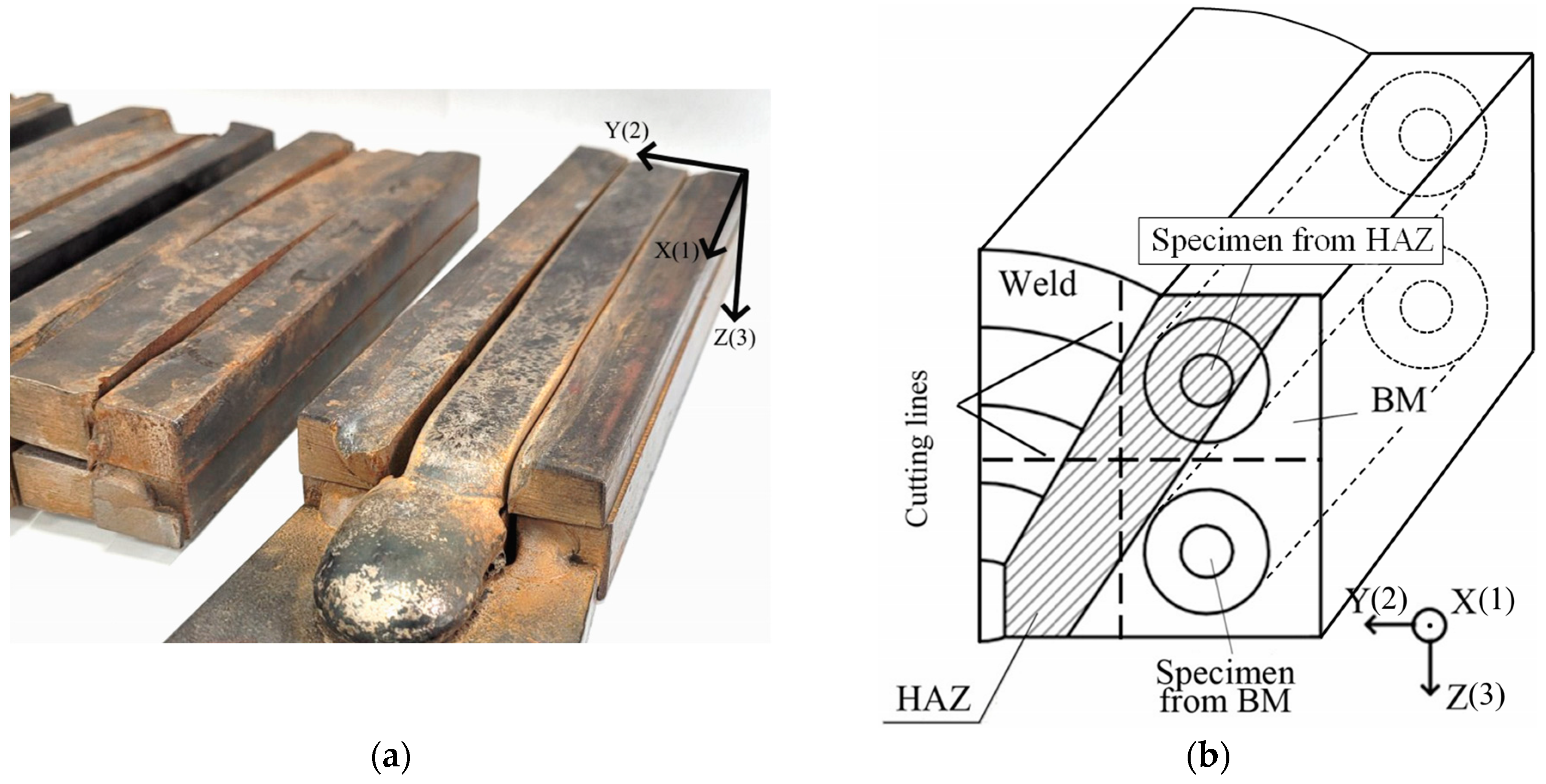
Two hot-rolled steel workpieces with a square cross-section of 30 × 30 mm2 (Figure 2a) were welded by manual arc welding on argon shielding gas in several passes. A specific welding mode was selected to ensure the heat-affected zone had a width of about 15 mm. Test specimens were made from the base metal (BM) and from the heat-affected zone (HAZ) of a welded joint (Figure 2b). Blanks were cut parallel to the weld through hydro-abrasive erosion. Next, we made round-cross-section specimens from blanks by lathing them with a special cooling liquid. Generally, the final specimens were not thermally affected.
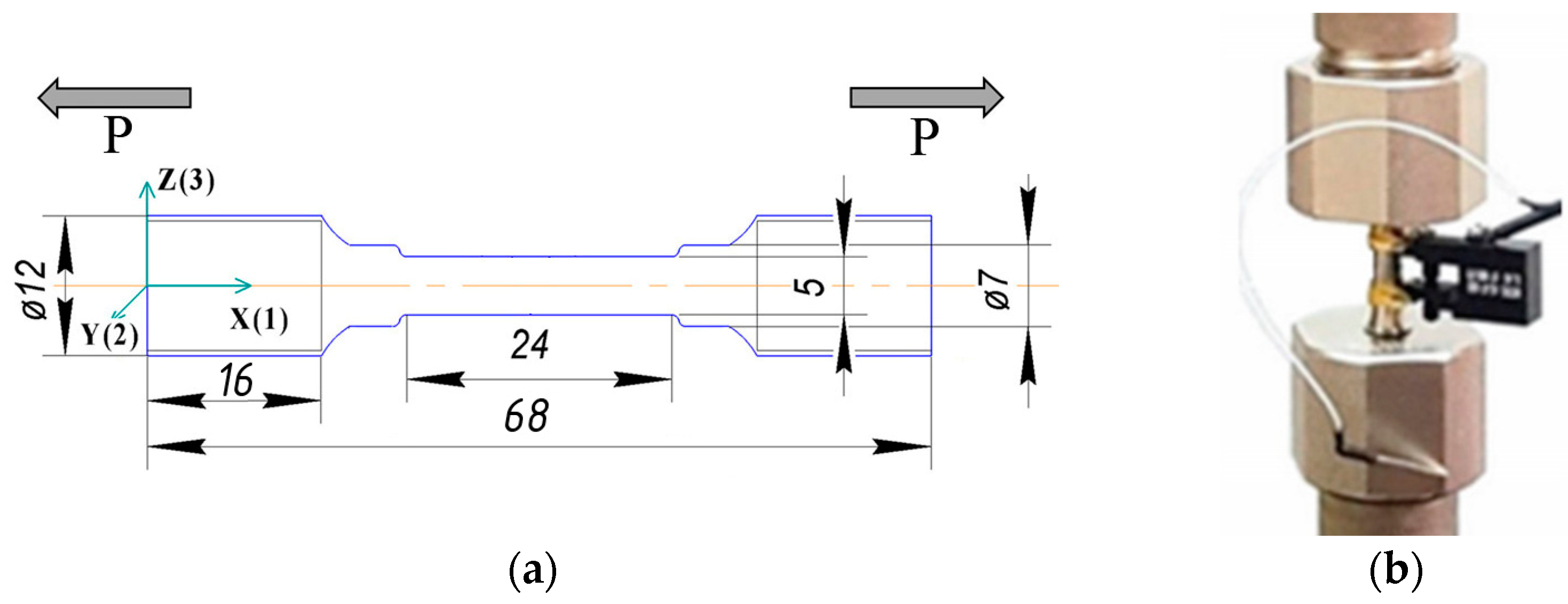
Figure 3a shows the geometric dimensions (in mm) of the test specimens. Two plane-parallel platforms 10 × 3 mm2 in size were cut out to enable ultrasonic measurements.

3.2. Low-Cycle Fatigue Tests

The specimens were subjected to cyclic tension–compression loading in strain-control mode using a BISS Nano UT-01-0025 servo-hydraulic testing machine (BISS, Bangalore, India) at a frequency of 1 Hz. Fatigue tests were carried out at a temperature of +22 °C. The strain ratio was equal to −1. Each specimen was loaded at a specific total strain amplitude, Δε, in accordance with the ASTM E1823 standard [32] until the formation of a 1 mm crack occurred, as visible to the naked eye. The stress amplitude, Δσ, and the number of cycles to failure, Nf, were determined. Table 3 shows the mechanical test data.
According to Table 3, specimens cut from the HAZ were destroyed, on average, 1.5 times faster compared to the specimens from the base metal.
The strain was controlled with a BISS AC-07-1005 extensometer (BISS, Bangalore, India) (Figure 3b). The applied stress was automatically calculated by the machine software as the ratio of the applied force to the cross-sectional area. The specimens were tested in stages. For each stage, after interrupting the test and unloading the specimen, ultrasonic measurements were carried out. The stage was 1500 cycles for a strain amplitude of 0.3%, 1000 cycles for a strain amplitude of 0.4, and 500 cycles for a strain amplitude of 0.5%.
For each tested specimen (for base metal and heat-affected zone), stress–strain hysteresis loops were automatically recorded for all loading cycles. There was no significant evolution of the hysteresis loops during fatigue. No redistribution between the elastic and plastic components of the strain was observed. As an example, Figure 4 shows the mid-life stress–strain hysteresis loops for the HAZ.
The results of the fatigue tests showed that the investigated steel actually underwent neither cyclic hardening nor cyclic softening. For example, the stress amplitude remained almost constant for the HAZ under fatigue, as shown in Figure 4b.

3.3. Ultrasonic Investigations

Ultrasonic measurements were carried out on the specimens in the unloaded state before the fatigue test and after each test stage in laboratory conditions at a temperature of +22 °C. The study was carried out with longitudinal, shear, and LCR waves.
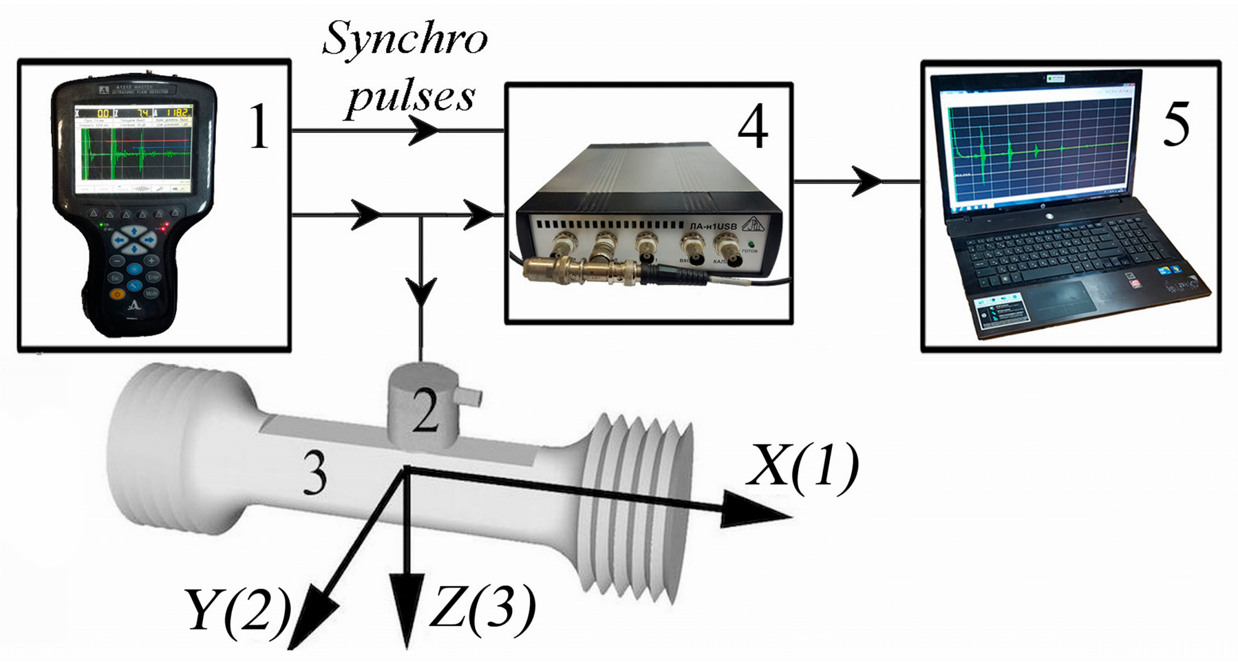
The ultrasonic data were obtained with a specially designed setup, as schematically shown in Figure 5. An ACS A1212 MASTER ultrasonic flaw detector (ACS Group, Saarbrücken, Germany) was used to generate the electrical pulses. An LA-n1USB digital oscilloscope (LLC “Rudnev-Shilyaev”, Moscow, Russia) and ADCLabSE (v.2.1.21344.2042) software were used to record an amplitude–time diagram of the pulses from the piezoelectric transducer on a PC. The sampling frequency was 1 GHz, and the time resolution was 1 ns.
The times of flight of one longitudinal, t33, and two shear (polarization in the mutually perpendicular directions along t31 and across t32, the loading axis) waves propagating through the thickness of the specimen between two plane-parallel platforms were measured using the echo method.
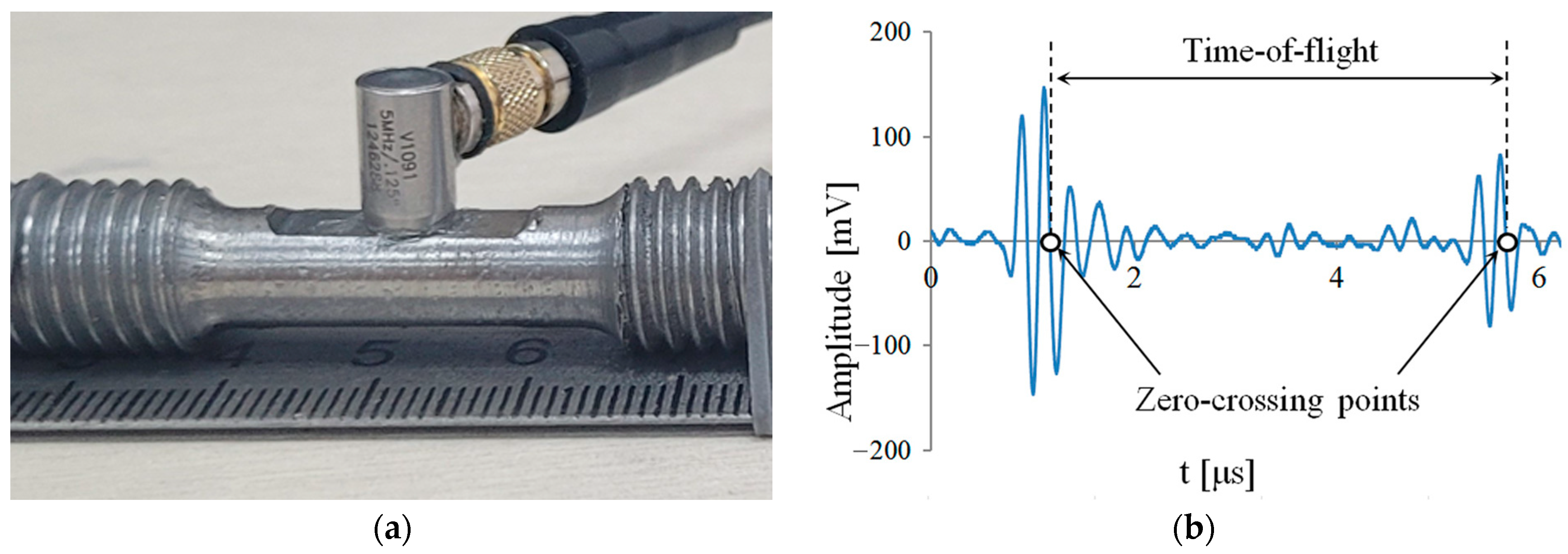
Olympus V1091 and V157 (Evident, Tokyo, Japan) wideband piezoelectric transducers were attached to the plane-parallel platform in the gauge section of the specimen to excite and receive longitudinal and shear waves, respectively. Figure 6a shows a method of installing a bulk wave transducer on a specimen. These transducers have a central frequency of 5 MHz and element sizes of 3.2 mm. Times of flight were measured between the first and second echo pulses at the zero-crossing points. A shear wave diagram is shown in Figure 6b.
Water-based ultrasound gel was used to ensure the acoustic contact of the longitudinal wave transducer, and epoxy resin was used for the shear wave transducer.
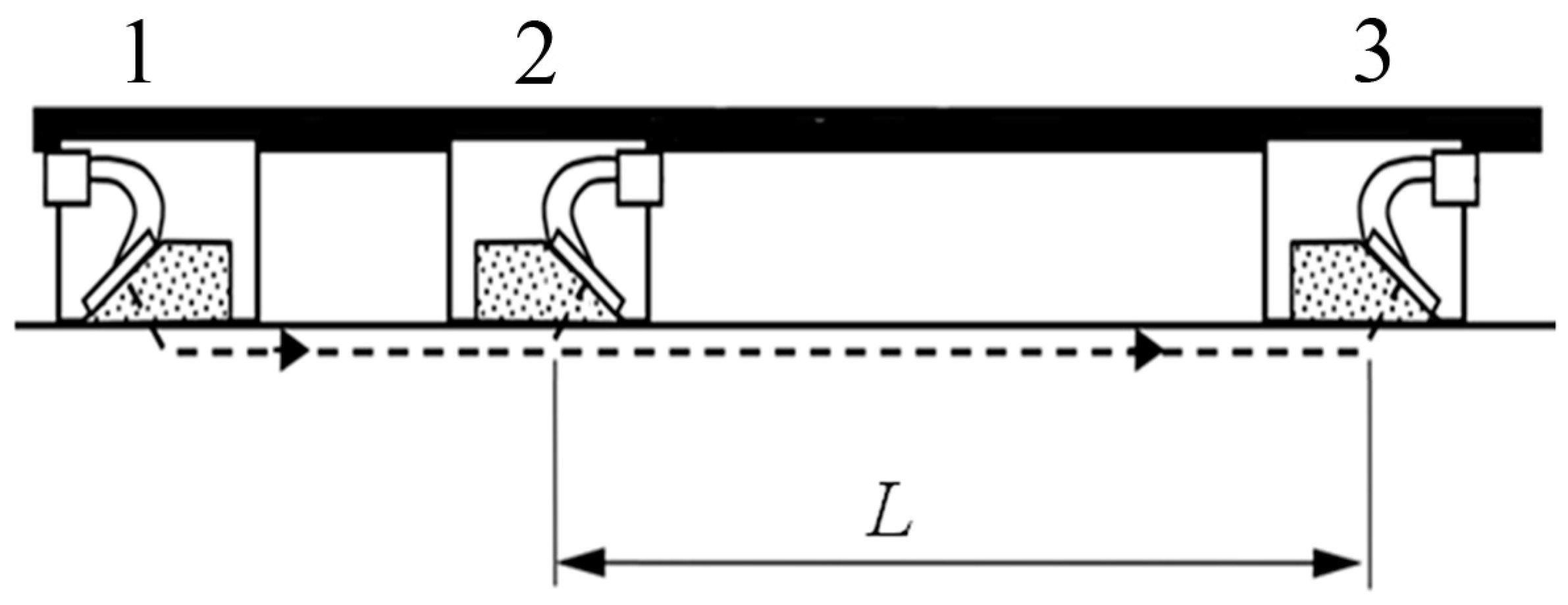
The times of flight of the LCR waves propagating along the specimen were determined through a differential measurement scheme (Figure 7).
This scheme consists of an emission transducer (ET), a first receiving transducer (RT1), and a second receiving transducer (RT2). The transducers are piezoceramic plates glued to a wedge.
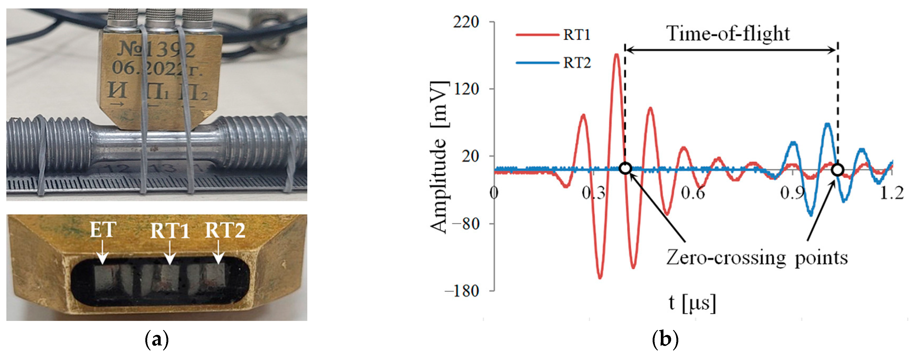
An experimental LCR transducer was manufactured, consisting of three transducers in one casing, in accordance with the scheme (Figure 8a). The piezoelectric plates’ frequency was 10 MHz, and the wedges were made of polymethyl methacrylate. Since the longitudinal wave velocity in polymethyl methacrylate is 2700 m/s, according to Formula (7), the wedge angle (first critical angle) is 27°. The emission and receiving of LCR waves were carried out at the specimens’ surfaces through the contact method using ultrasound gel. The differential measurement scheme made it possible to compensate for the influence of the thermal expansion of the wedge and significantly reduce the layer contact fluid influence and delay lines in the cables [33,34]. The calibration of the LCR transducer was carried out on samples with a known longitudinal wave propagation velocity. From the calibration results and taking into account the choice of in-phase points, the measuring base, L, between the two receiving transducers was 3.760 ± 0.005 mm. In accordance with Formula (7), the propagation depth of the LCR waves at 10 MHz was 0.5 mm.
The times of flight of the LCR waves, t 11 L C R , were measured between the signals from the first and second receiving transducers. The zero-crossing points at the transition from the minimum to the maximum in the signal were taken as in-phase points in the pulses (Figure 8b).
At each stage, the ultrasonic measurements were repeated ten times and then averaged. High accuracy was ensured by maintaining stable contact and exact positioning of the transducer. The absolute error in measuring the time of flight of shear, longitudinal, and LCR waves was no more than 1 ns.
The velocities of longitudinal, V33, and shear waves, polarized along V31 and across the V32 loading axis, are calculated using the following formulas:
V 33 = 2 h t 33 ,           V 31 = 2 h t 31 ,           V 32 = 2 h t 32 .
where h is the thickness of the specimens (measured using a micrometer).
The LCR wave propagation velocity was calculated as follows:
V 11 L C R = L t 11 L C R
The main contribution to the velocity error comes from measuring the distance traveled by the elastic wave. The absolute error in the shear waves’ velocity was 3 m/s, and that of the longitudinal and LCR waves was 5 m/s.
The acoustic birefringence, the module ratios, and the parameter D were determined using Formulas (3), (4) and (8), respectively. The absolute error in determining the acoustic birefringence did not exceed 4 × 10⁻⁴; in determining the module ratios, it did not exceed 2 × 10⁻⁴; and in determining parameter D, it did not exceed 1 × 10⁻³.
The changes in the velocities, ΔV, acoustic birefringence, ΔB, parameter, ΔD, and the module ratios, Δ(C33/C55) and Δ(C33/C44), were calculated as the difference between the subsequent value and the initial one.

3.4. Metallographic Investigations

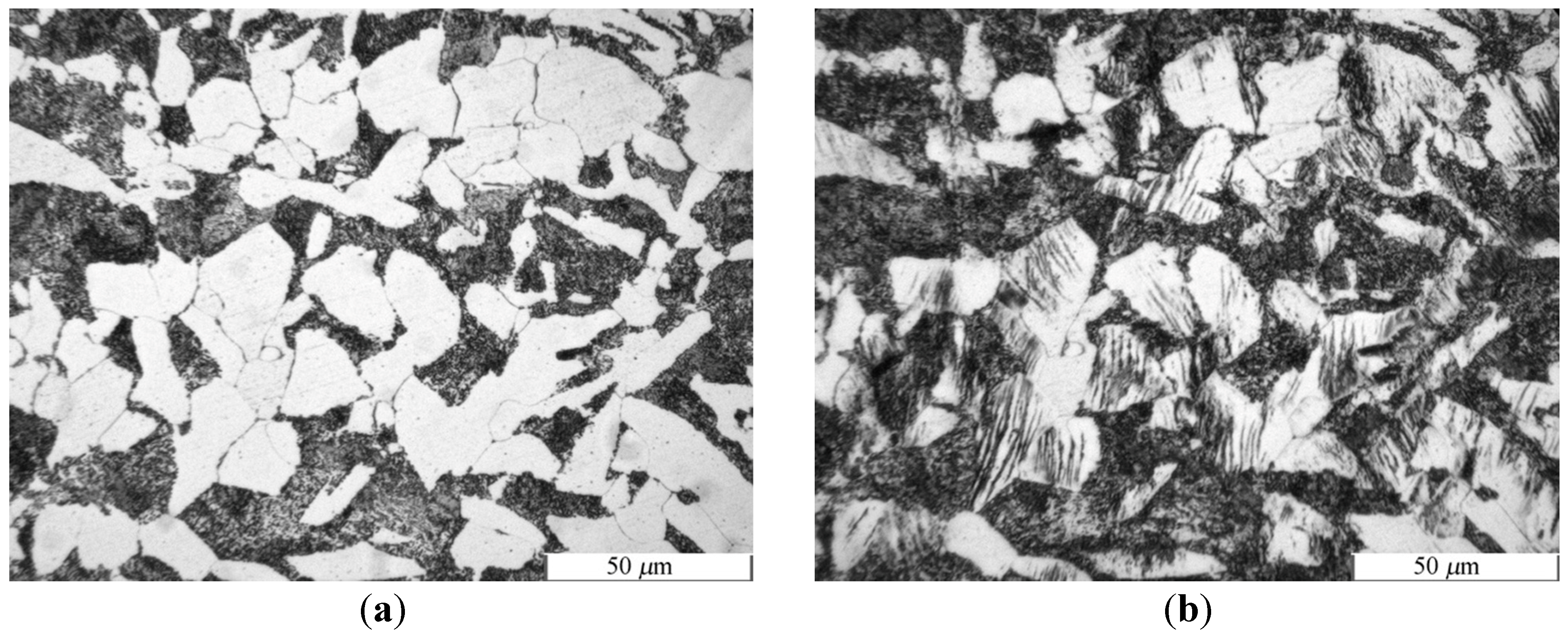
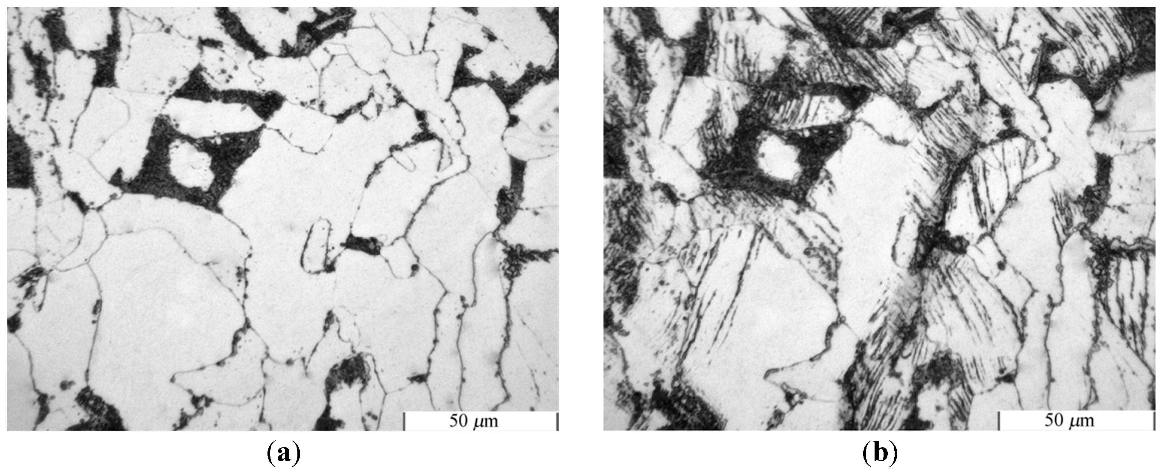
For each tested specimen (for the base metal and heat-affected zone), microstructure images were obtained. The surface was first mechanically polished and then chemically etched within 10 s using a 5% nitric acid water solution to reveal the grain boundaries. The microstructure was observed using a ZEISS Axio Observer optical microscope (ZEISS AG, Oberkochen, Germany). The microstructures of the base material and the heat-affected zone before and after testing are shown in Figure 9 and Figure 10.
The structure of the HAZ differs from that of the BM and corresponds to the welded joint’s overheating area. The grain size of the base metal is 27 µm, and that of the heat-affected zone is 52 µm. It follows from observations that persistent slip bands (PSBs) appear in the ferrite grains already in the first stage of the fatigue test. PSBs have a prevalent orientation across the axis of loading.
A more detailed study of changes in surface topography was carried out using a Keyence VHX 1000 universal digital microscope (KEYENCE CORPORATION OF AMERICA, Itasca, IL, USA). The results are presented in Section 5.

4. Results

The velocities of the longitudinal and shear waves, calculated by Formula (9), and the LCR wave velocities, calculated by Formula (10), in accordance with the number of cycles, N, are presented in Table 4.
The shear wave velocities, V31, V32, and V33 for tests B1, B2, and B3, do not change (Figure 11). For tests B2 and B3, a monotonic decrease in the velocity of the shear waves, V31, is observed. The intensity of the V31 velocity change increases with increasing amplitude deformation.
Compared to the BM, the shear and longitudinal waves’ velocities in the HAZ change more intensively (Figure 12).
A monotonous velocity decrease in V31 is observed in the HAZ (Figure 12a). The velocity of V32 for the H1 test remains almost unchanged (Figure 12b). A monotonous velocity decrease in V32 is observed for tests H2 and H3. The velocity of the longitudinal waves V33 increases monotonically (Figure 12c).
The changes in the velocities of the LCR waves, V 11 L C R , in the BM can be divided into two stages: first, there is a decrease; then, after N/Nf = 0.2–0.3, there is an increase (Figure 13a).
A gradual change in the LCR wave velocity, V 11 L C R , is observed for the HAZ: a slight increase in the initial stage (N/Nf = 0.25), then a decrease (N/Nf = 0.6–0.7), and then rapid growth, as shown in Figure 13b.
Thus, the shear wave velocities V31 and the velocities V 11 L C R for both the BM and the HAZ turned out to be the most sensitive to fatigue.

5. Discussion

Metallographic studies indicate the active formation of PSBs (Figure 3), especially in the HAZ (Figure 4), which are a consequence of the movement of active dislocations. We carried out more detailed studies in our work [35]. An increase in dislocation density reduces the velocity of bulk ultrasonic waves [36].
The PSBs detected on the surface were predominantly oriented across the loading axis. The intrusion–extrusion relief observed on the surface displays the movement of dislocations in certain crystallographic directions in the volume of the material, as shown in Figure 14. Accordingly, defects (mesodefects, dislocations, etc.) formed inside the material have a prevalent orientation and affect the shear waves’ velocity polarized along the loading axis [37]. We suppose that the formation of such oriented defects leads to a monotonic decrease in the shear wave velocity polarized along the loading axis (Figure 11a and Figure 12a).
There was no change in the velocity of the longitudinal waves, V33, in the BM. For the HAZ, a linear increase in the velocity of the longitudinal waves is observed, which may be due to the same influence of texture changes.
The decrease in the LCR wave velocities, V 11 L C R (for BM up to N/Nf = 0.25 and for HAZ from N/Nf = 0.25 to N/Nf = 0.6–0.7), may be associated with PSB formation. Accordingly, these prevalent orientation defects influence the LCR wave velocity in the same way as the shear wave velocity becomes polarized along the loading axis.
Another factor that can affect the decrease in the propagation velocities of LCR waves is an increase in the material surface roughness. The intensity of the relief change is related to the magnitude of the strain amplitude. For example, for test H3, the relief changed significantly after N = 1500, and the maximum depression was from 14 µm to 21 µm (Figure 14). An increase in the effective acoustic path with a constant measurement base, L, for the LCR wave sensor leads to a decrease in velocity when calculated according to formula (10).
The subsequent increase in the LCR wave velocity (for the BM from N/Nf = 0.25 to N/Nf = 1 and for the HAZ from N/Nf = 0.6–0.7) could be associated with several factors. One of the factors may be the influence of changes in the metal’s crystallographic texture. Another factor may be the partial transformation of the LCR wave into a longitudinal wave due to structural transformations in the surface layer, the velocity of which is approximately 10% higher [38]. It is known that in the later stages of fatigue, grain fragmentation and grinding can occur. The authors in [39] showed that the velocity of LCR waves increases with decreasing grain size.
For the HAZ, the slight increase in the LCR wave velocities in the initial stage (from N/Nf = 0 to N/Nf = 0.25) may be associated with internal stress relaxation.
To assess the material’s condition, it is advisable to use dimensionless parameters, for the calculation of which there is no need to measure the material thickness. Therefore, dimensionless parameters (except for parameter D) can be determined with one-sided access to the structure and with less error, in contrast to the elastic wave velocities.
The acoustic birefringence, B, calculated by Formula (3), the parameter D, calculated by Formula (8), and the module ratios C33/C44 and C33/C55, calculated by Formula (4), are presented in Table 5.
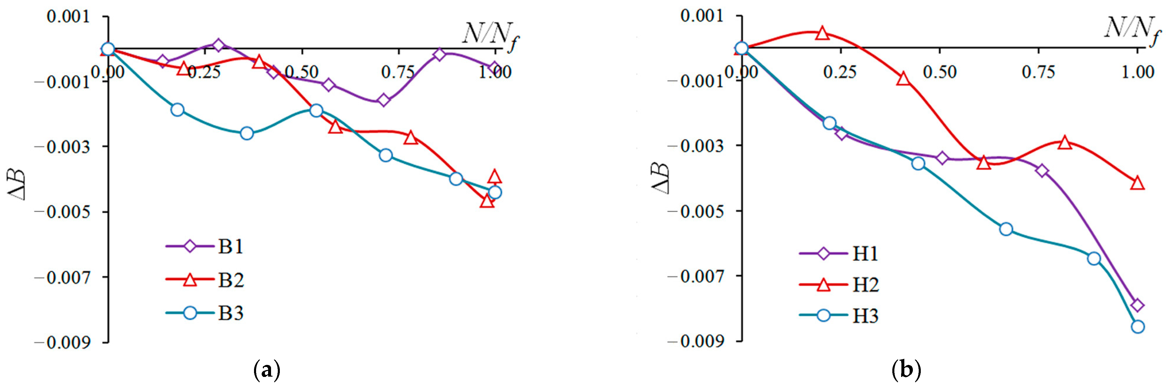
The acoustic birefringence changes in a similar way with velocity, V31 (Figure 15). The monotonous decrease in ΔB is due to the formation of predominantly oriented microdefects.
The behavior of the parameter D is due to the change in velocity V 11 L C R and is associated with the same factors (Figure 16).
A monotonic decrease in ΔB over the fatigue lifetime and a monotonic growth in ΔD after the half-life can be used to determine the material state of a welded joint under fatigue.
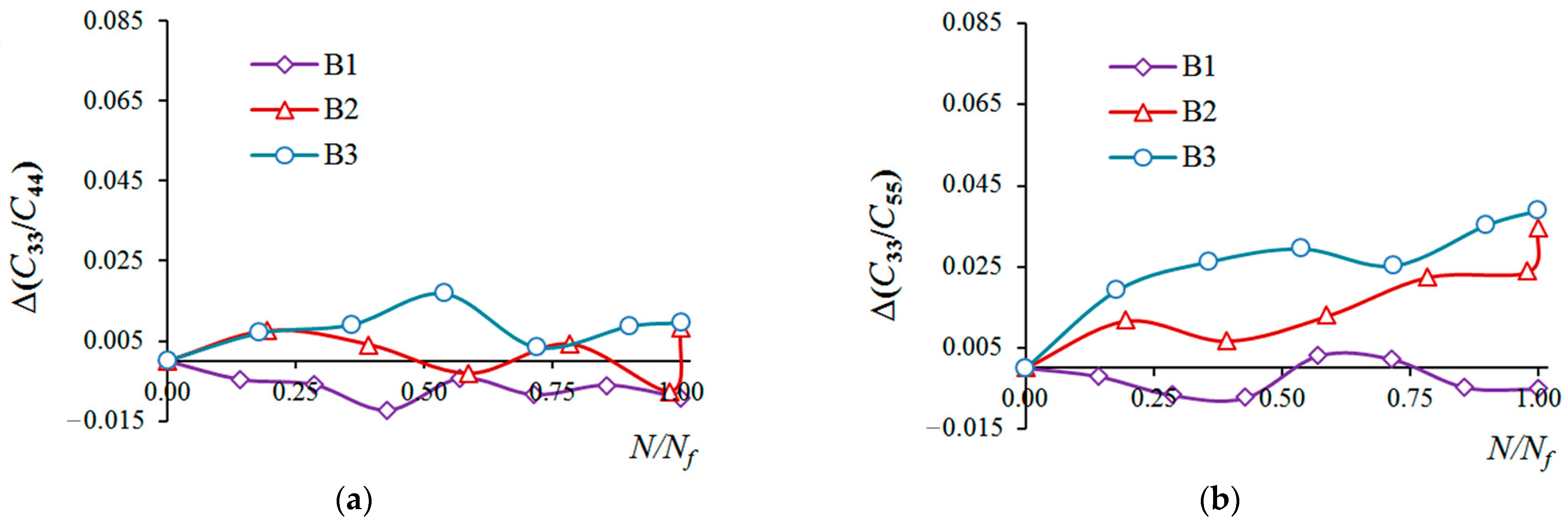
The module ratios, C33/C44, for the base metal do not change (Figure 17a). For test B1, the C33/C55 ratio also does not change (Figure 17b). For tests B2 and B3, C33/C55 grows monotonically with Δε.
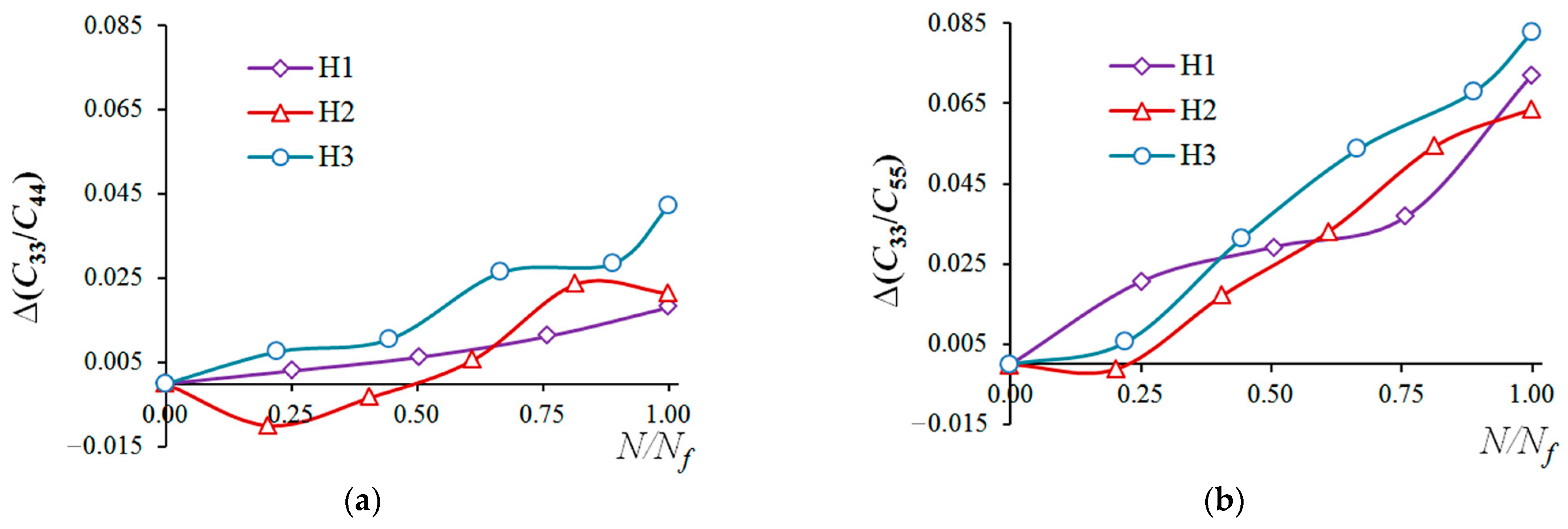
For the HAZ, Δ(C33/C44) and Δ(C33/C55) grow monotonically, as shown in Figure 18. The module ratios in the HAZ Δ(C33/C55) increase according to a linear law, and the intensity of their change is the greatest here.
For the HAZ, the module ratio Δ(C33/C55) does not depend on the strain amplitude, which can be used to calculate the remaining service life, R, during material fatigue:
R = 1 N N f = 1 14.2 Δ C 33 C 55
As a result of ultrasonic studies, it was found that the acoustic parameters change most intensively in the specimens cut from the HAZ. This effect can be explained by the large grain size in the heat-affected zone (overheating area) compared to the base material. It is known that, in accordance with the Hall–Petch law [40,41], as the grain increases, the yield strength decreases. The increased plasticity of the HAZ causes more intense movement of dislocations and changes in the microstructure. It is also necessary to take into account that in large grains more extended microdefects are formed.
The proposed method is based on determining dimensionless first-order acoustic parameters. Acoustic birefringence is insensitive to the coupling layer between the sensor and the test object and is not sensitive to the waviness or roughness of a surface. Therefore, there is no need to know the acoustical patch or thickness, as it can be implemented with single-sided access. This increases the reliability of using this method in industrial facilities, in contrast, for example, to nonlinear ultrasonic coefficient methods [42], the main problem of which is a change in the waveform due to many factors.

6. Conclusions

In this work, the influence of fatigue on the acoustic parameters of the base metal and the heat-affected zone of a welded joint made of ASTM 1020 carbon steel was experimentally investigated. According to the mechanical test data, it was found that the specimens from the overheating zone of the welded joint were destroyed approximately 1.5 times faster than the specimens from the base metal.
It was established that the elastic waves’ velocities change most intensively in the heat-affected zone. The linear decrease in the shear wave velocities polarized along the specimen’s loading axis is explained by the formation of linear microdefects predominantly oriented across the loading axis. The nonmonotonic change in the LCR wave velocity is explained by two factors: microdefect formation and the change in the texture of the subsurface layer. It was found that a monotonic decrease in acoustic birefringence occurs more intensely in the heat-affected zone. It was observed that parameter D, calculated through the ratio of the longitudinal and LCR waves’ velocities (similar to the acoustic birefringence of shear waves), changes states. It was found that the ratios of modules C33/C44 and C33/C55 increase most intensively in the heat-affected zone. The linear relationship between the cycle ratio and the change in C33/C55 is proposed to be used to calculate the remaining fatigue lifetime and predict the moment of failure using the acoustic method.

Author Contributions

Conceptualization, A.G.; experimental methodology, A.G. and A.S.; validation, V.K., A.G. and A.S.; formal analysis, V.K. and A.G.; writing—original draft preparation, A.G.; writing—review and editing, V.K. and A.S. All authors have read and agreed to the published version of the manuscript.

Funding

The research was financially funded by the Russian Science Foundation, grant number 21-79-10395, https://rscf.ru/en/project/21-79-10395/ (27 June 2024).

Data Availability Statement

The original contributions presented in the study are included in the article, and further inquiries can be directed to the corresponding author.

Conflicts of Interest

The authors declare no conflicts of interest.

References

  1. Wolfgang, F. Fatigue Analysis of Welded Joints: State of Development. Marine Struct. 2003, 16, 185–200. [Google Scholar] [CrossRef]
  2. Veerababu, J.; Goyal, S.; Atikukke, N. Studies on creep-fatigue interaction behavior of Grade 92 steel and its weld joints. Int. J. Fatigue 2021, 149, 106307. [Google Scholar] [CrossRef]
  3. Nishikawa, H.-a.; Furuya, Y.; Igi, S.; Goto, S.; Briffod, F.; Shiraiwa, T.; Enoki, M.; Kasuya, T. Effect of microstructure of simulated heat-affected zone on low-to high-cycle fatigue properties of low-carbon steels. Fatigue Fract. Eng. Mater. Struct. 2020, 43, 1239–1249. [Google Scholar] [CrossRef]
  4. Wisner, B.; Mazur, K.; Kontsos, A. The use of nondestructive evaluation methods in fatigue: A rewiew. Fatigue Fract. Eng. Mater. Struct. 2020, 43, 859–878. [Google Scholar] [CrossRef]
  5. Ensminger, D.; Bond, L.J. Ultrasonics: Fundamentals, Technologies, and Applications, 3rd ed.; CRC Press: Boca Raton, FL, USA, 2011. [Google Scholar]
  6. Vanniamparambil, P.A.; Bartoli, I.; Hazeli, K.; Cuadra, J.; Schwartz, E.; Saralaya, R.; Kontsos, A. An integrated structural health monitoring approach for crack growth monitoring. J. Int. Mat. Syst. Struct. 2012, 23, 1563–1573. [Google Scholar] [CrossRef]
  7. Pan, S.; Yu, G.; He, X.; Li, S.; Zhang, Y.; Li, Q. Collective evolution of surface microcrack for compacted graphite iron under thermal fatigue with variable amplitude. Int. J. Fatigue 2019, 118, 139–149. [Google Scholar] [CrossRef]
  8. Chen, E.Y.; Sauer, S.; Meshii, M.; Tucker, W.T. Fatigue microcrack distributions and the reability of a nickel base superalloy. Int. J. Fatigue 1997, 19, 75–82. [Google Scholar] [CrossRef]
  9. Besel, M.; Brueckner-Foit, A. Surface damage evolution of engineering steel. Fatigue Fract. Eng. Mater. Struct. 2008, 31, 885–891. [Google Scholar] [CrossRef]
  10. Mishakin, V.V.; Klyushnikov, V.A.; Gonchar, A.V.; Kachanov, M. On assessing damage in austenitic steel based on combination of the acoustic and eddy current monitoring. Int. J. Eng. Sci. 2019, 135, 17–22. [Google Scholar] [CrossRef]
  11. Cantrell, J.H.; Yost, W.T. Nonlinear ultrasonic characterization of fatigue microstructures. Int. J. Fatigue 2001, 23, 487–490. [Google Scholar] [CrossRef]
  12. Gupta, S.; Ray, A.; Keller, E. Online fatigue damage monitoring by ultrasonic measurements: A symbolic dynamics approach. Int. J. Fatigue 2007, 29, 1100–1114. [Google Scholar] [CrossRef]
  13. Gonchar, A.V.; Solovyov, A.A. Ultrasonic and metallographic study of the heat-affected zone of a carbon steel welded joint under plastic deformation and fatigue. J. Appl. Mech. Tech. Phys. 2023, 64, 921–928. [Google Scholar] [CrossRef]
  14. Makowska, K.; Piotrowski, L.; Kowalewski, Z.L. Prediction of the Mechanical Properties of P91 Steel by Means of Magneto-acoustic Emission and Acoustic Birefringence. J. Nondestruct. Eval. 2017, 36, 43. [Google Scholar] [CrossRef]
  15. Piotrowski, L.; Augustyniak, B.; Chmielewski, M. On the possibility of the application of magnetoacoustic emission intensity measurements for the diagnosis of thick-walled objects in the industrial environment. Meas. Sci. Technol. 2010, 21, 035702. [Google Scholar] [CrossRef]
  16. Gonchar, A.V.; Mishakin, V.V.; Klyushnikov, V.A. The effect of phase transformations induced by cyclic loading on the elastic properties and plastic hysteresis of austenitic stainless steel. Int. J. Fatigue 2018, 106, 153–158. [Google Scholar] [CrossRef]
  17. Hirsekorn, S.; Andel, P.; Netzelmann, U. Ultrasonic methods to detect and evaluate damage in steel. Nondestruct. Test. Eval. 2000, 15, 373–393. [Google Scholar] [CrossRef]
  18. Pei, N.; Zhao, B.; Zhao, X.; Liu, Z.; Bond, L.J. Analysis of the directivity of Longitudinal Critically Refracted (LCR) waves. Ultrasonics 2021, 113, 106359. [Google Scholar] [CrossRef]
  19. Javadi, Y.; Pirzaman, H.M.; Raeisi, M.H.; Najafabadi, M.A. Ultrasonic Evaluation of Welding Residual Stresses in Stainless Steel Pressure Vessel. J. Press. Vessel. Technol. 2013, 135, 041502. [Google Scholar] [CrossRef]
  20. Buenos, A.A.; Jr, P.P.; Mei, P.R.; Santos, A.A. Influence of Grain Size on the Propagation of LCR Waves in Low Carbon Steel. J. Nondestruct. Eval. 2014, 33, 562–570. [Google Scholar] [CrossRef]
  21. Ferrand, A.; Darmon, V.; Chatillon, S.; Deschamps, M. Modeling of ray paths of head waves on irregular interfaces in TOFD inspection for NDE. Ultrasonics 2014, 54, 1851–1860. [Google Scholar] [CrossRef]
  22. Zernov, V.; Fradkin, L.; Gautesen, A.; Darmon, M.; Calmon, P. Wedge diffraction of a critically incident Gaussian beam. Wave Motion 2013, 50, 708–722. [Google Scholar] [CrossRef]
  23. Huet, G.; Darmon, M.; Lhéemery, A.; Mahaut, S. Modeling of corner echo ultrasonic inspection with bulk and creeping waves. In Ultrasonic Wave Propagation in Non Homogeneous Media; Leger, A., Deschamps, M., Eds.; Springer Proceedings in Physics, 128; Springer: Berlin/Heidelberg, Germany, 2009. [Google Scholar] [CrossRef]
  24. Darmon, M.; Ferrand, A.; Dorval, V.; Chatillon, S.; Lonné, S. Recent modelling advances for ultrasonic TOFD inspections. AIP Conf. Proc. 2015, 1650, 1757–1765. [Google Scholar] [CrossRef]
  25. Ermolov, I.N. Progress in the theory of ultrasonic flaw detection. Problems and prospects. Russ. J. Nondestruct. Test. 2004, 40, 655–678. [Google Scholar] [CrossRef]
  26. Fedorov, F.I. Theory of Elastic Waves in Crystals; Springer: New York, NY, USA, 1968. [Google Scholar]
  27. Gonchar, A.V.; Mishakin, V.V.; Klyushnikov, V.A.; Kurashkin, K.V. Variation of Elastic Characteristics of Metastable Austenite Steel under Cycling Straining. Tech. Phys. 2017, 62, 537–541. [Google Scholar] [CrossRef]
  28. Bray, D.E. Ultrasonic Stress Measurement and Material Characterization in Pressure Vessels, Piping and Welds. J. Press. Vessel. Technol. 2002, 124, 326–335. [Google Scholar] [CrossRef]
  29. Bray, D.E.; Griffin, R.B. Monitoring Hydrogen Release from 4140 Steel Using the LCR Ultrasonic Technique. In Nondestructive Testing of Materials and Structures; Springer: Dordrecht, The Netherlands, 2011; pp. 689–694. [Google Scholar] [CrossRef]
  30. Liu, Y.; Liu, E.; Chen, Y.; Wang, X.; Sun, C.; Tan, J. Study on Propagation Depth of Ultrasonic Longitudinal Critically Refracted (LCR) Wave. Sensors 2020, 20, 5724. [Google Scholar] [CrossRef] [PubMed]
  31. ASTM E8/E8M-11; Standard Test Methods for Tension Testing of Metallic Materials. ASTM International: West Conshohocken, PA, USA, 2011.
  32. ASTM E1823-13; Standard Terminology Relating to Fatigue and Fracture Testing. ASTM International: West Conshohocken, PA, USA, 2013.
  33. Szelążek, J. Sets of Piezoelectric Probeheads for Stress Evaluation with Subsurface Waves. J. Nondestruct. Eval. 2013, 32, 188–199. [Google Scholar] [CrossRef]
  34. Liu, H.; Li, Y.; Li, T.; Zhang, X.; Liu, Y.; Liu, K.; Wang, Y. Influence factors analysis and accuracy improvement for stress measurement using ultrasonic longitudinal critically refracted (LCR) wave. App. Acoust. 2018, 141, 178–187. [Google Scholar] [CrossRef]
  35. Gonchar, A.V.; Kurashkin, K.V.; Andreeva, O.V.; Anosov, M.S.; Klyushnikov, V.A. Fatigue life prediction of structural steel using acoustic birefringence and characteristics of persistent slip bands. Fatigue Fract. Eng. Mat. Struct. 2021, 45, 101–112. [Google Scholar] [CrossRef]
  36. Truell, R.; Elbaum, C.; Chick, B.B. Ultrasonic Methods in Solid State Physics; Academic Press: New York, NY, USA; London, UK, 1969. [Google Scholar]
  37. Mishakin, V.V.; Gonchar, A.V.; Kirikov, S.V.; Klyushnikov, V.A. Evaluation of condition of low-carbon steels experiencing plastic deformation using the effect of acoustic birefringence. Nondestruct. Test. Eval. 2021, 36, 225–235. [Google Scholar] [CrossRef]
  38. Viktorov, I.A. Rayleigh and Lamb Waves: Physical Theory and Applications; Plenum Press: New York, NY, USA, 1967. [Google Scholar]
  39. Sarpün, İ.H.; Kılıçkaya, M.S.; Tuncel, S. Mean grain size determination in marbles by ultrasonic velocity techniques. NDT E Int. 2005, 38, 21–25. [Google Scholar] [CrossRef]
  40. Petch, N.J. The cleavage strength of polycrystals. J. Iron Steel Inst. 1953, 174, 25–28. [Google Scholar]
  41. Sylwestrowicz, W.; Hall, E.O. The Deformation and Ageing of Mild Steel. Proc. Phys. Soc. B. 1951, 64, 495–502. [Google Scholar] [CrossRef]
  42. Yan, X.; Wang, H.; Fan, X. Research Progress in Nonlinear Ultrasonic Testing for Early Damage in Metal Materials. Materials 2023, 16, 2161. [Google Scholar] [CrossRef] [PubMed]
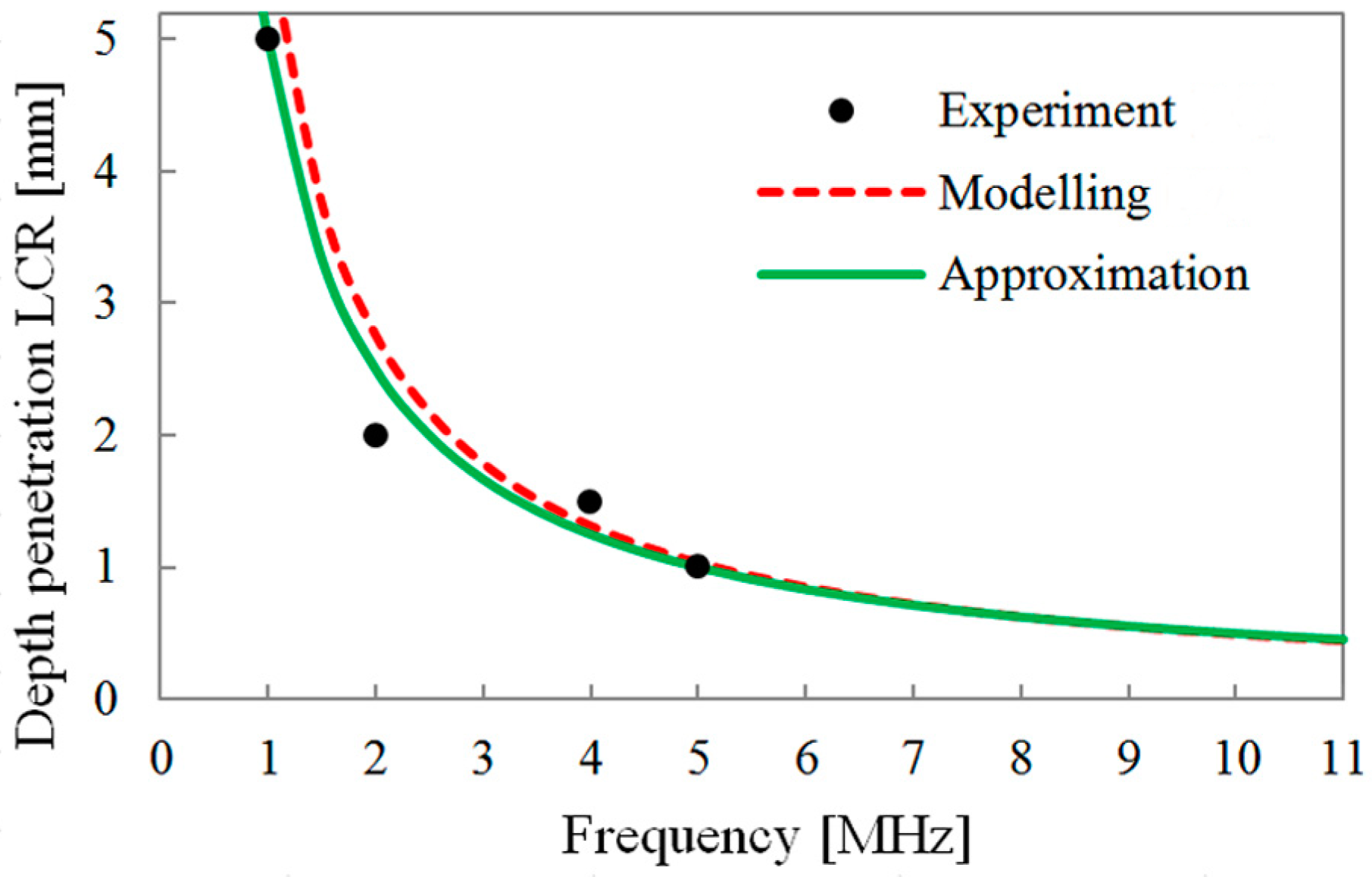
Figure 1. Relationship between the LCR wave propagation depth and frequency: “Experiment”—[19]; “Modelling”—[30]; “Approximation”—calculated by Equation (7).
Acoustics 06 00032 g001
Figure 2. Workpiece (a) and diagram of cutting the test specimens (b).
Acoustics 06 00032 g002
Figure 3. The specimen (a) is in the grips of a test machine with an extensometer installed (b).
Acoustics 06 00032 g003
Figure 4. Mid-life hysteresis loops (a) and stress amplitude evolution (b) for the HAZ.
Acoustics 06 00032 g004
Figure 5. Experimental setup: 1—generator of electrical pulses; 2—piezoelectric transducer; 3—specimen; 4—digital oscilloscope; 5—PC.
Acoustics 06 00032 g005
Figure 6. Transducer of bulk waves (a), amplitude–time diagram of echo pulses of bulk (shear) waves, and methodology for measuring time of flight (b).
Acoustics 06 00032 g006
Figure 7. Differential measurement scheme for LCR waves: 1—emission transducer (ET); 2—first receiving transducer (RT1); 3—second receiving transducer (RT2); dotted arrow—LCR wave direction.
Acoustics 06 00032 g007
Figure 8. Transducer of LCR waves (a), amplitude–time diagram of LCR waves, and methodology for measuring the time of flight of LCR waves (b).
Acoustics 06 00032 g008
Figure 9. Microstructure of base metal in initial state (a) and after failure (b).
Acoustics 06 00032 g009
Figure 10. Microstructure of heat-affected zone in initial state (a) and after failure (b).
Acoustics 06 00032 g010
Figure 11. The effect of the change in velocities V31 (a), V32 (b), and V33 (c) on the BM.
Acoustics 06 00032 g011
Figure 12. The effect of the change in velocities V31 (a), V32 (b), and V33 (c) on the HAZ.
Acoustics 06 00032 g012
Figure 13. Change in the velocity V 11 L C R on the BM (a) and HAZ (b).
Acoustics 06 00032 g013
Figure 14. Change in surface topography under the fatigue of a specimen cut from the HAZ: (a)—initial state; (b)—after N = 1500.
Acoustics 06 00032 g014
Figure 15. Change in acoustic birefringence during cyclic loading for the BM (a) and HAZ (b).
Acoustics 06 00032 g015
Figure 16. Change in parameter D during cyclic loading for the BM (a) and HAZ (b).
Acoustics 06 00032 g016
Figure 17. Change in the module ratios C33/C44 (a) and C33/C55 (b) for the BM.
Acoustics 06 00032 g017
Figure 18. Change in the module ratios C33/C44 (a) and C33/C55 (b) for the HAZ.
Acoustics 06 00032 g018
Table 1. Chemical composition of investigated steel (weight %).
FeCSiMnNiCrCuAsSP
>98.70.180.210.560.080.110.080.04<0.01<0.02
Table 2. Mechanical properties of investigated steel as received.
Yield Tensile Strength, MPaUltimate Tensile Strength, MPaElongation at Break, %
270 ± 10450 ± 1028 ± 2
Table 3. Mechanical test data.
Test No.TypeΔε, %Δσ, MPaNf
B1Base Metal0.330610,500
B20.43475100
B30.53792780
H1Heat-affected zone0.33085900
H20.43144900
H30.53482250
Table 4. Ultrasonic waves’ velocities.
Test No.N, Cycles V 31 , m/s V 32 , m/s V 33 , m/s V 11 L C R , m/s
B103272326859845941
15003268326659755931
30003274327059825907
45003272327159785919
60003269326959825924
75003268327059795936
90003274327159845940
10,5003273327259835944
B203279327760015930
10003273327360005911
20003276327560015902
30003276328160065903
40003274328160115914
50003265327859955929
51003264327560045945
B303275327259785939
5003265326859785897
10003267327259875921
15003262326559825928
20003263327159805936
25003261327159865947
27803255326659785952
H103259327459845869
15003252327559905904
30003252327759975901
45003249327659985914
59003238327860095992
H203258327059905853
10003253326359945863
20003248326259995846
30003245326860055840
40003244326560165858
49003240326560105897
H303255327159725874
5003254327759745884
10003241326959775872
15003236327159855832
20003226326359825877
22503224326859875889
Table 5. Dimensionless acoustic parameters.
Test NoN, CyclesBDC33/C44C33/C55
B100.0011−0.0073.3533.345
15000.0007−0.0083.3483.343
30000.0012−0.0133.3473.339
45000.0004−0.0103.3403.338
60000.0000−0.0103.3483.348
7500−0.0005−0.0073.3443.347
90000.0009−0.0073.3473.341
10,5000.0005−0.0063.3443.340
B200.0007−0.0123.3543.349
10000.0001−0.0153.3613.361
20000.0003−0.0173.3583.356
3000−0.0017−0.0173.3503.362
4000−0.0020−0.0163.3583.371
5000−0.0040−0.0113.3463.373
5100−0.0032−0.0103.3623.383
B300.0009−0.0073.3393.333
500−0.0009−0.0143.3463.353
1000−0.0016−0.0113.3483.360
1500−0.0010−0.0093.3563.363
2000−0.0023−0.0073.3433.358
2500−0.0030−0.0063.3483.369
2780−0.0035−0.0043.3493.372
H10−0.0045−0.0193.3423.372
1500−0.0071−0.0143.3453.393
3000−0.0079−0.0163.3483.401
4500−0.0083−0.0143.3533.409
5900−0.0124−0.0033.3603.444
H20−0.0036−0.0233.3623.386
1000−0.0032−0.0223.3523.385
2000−0.0045−0.0263.3593.404
3000−0.0071−0.0283.3673.419
4000−0.0065−0.0273.3853.441
4900−0.0078−0.0193.3833.450
H30−0.0050−0.0173.3333.366
500−0.0073−0.0153.3413.372
1000−0.0085−0.0173.3433.398
1500−0.0105−0.0243.3593.420
2000−0.0114−0.0173.3613.434
2250−0.0135−0.0163.3753.449
Disclaimer/Publisher’s Note: The statements, opinions and data contained in all publications are solely those of the individual author(s) and contributor(s) and not of MDPI and/or the editor(s). MDPI and/or the editor(s) disclaim responsibility for any injury to people or property resulting from any ideas, methods, instructions or products referred to in the content.