Article

A Power Law Reconstruction of Ultrasound Backscatter Images

Department of Electrical and Computer Engineering, University of Rochester, Rochester, NY 14627, USA
Acoustics 2024, 6(3), 782-791; https://doi.org/10.3390/acoustics6030043
Submission received: 30 April 2024 / Revised: 20 August 2024 / Accepted: 28 August 2024 / Published: 31 August 2024

Abstract

:
Ultrasound B-scan images are traditionally formed from the envelope of the received radiofrequency echoes, but the image texture is dominated by granular speckle patterns. Longstanding efforts at speckle reduction and deconvolution have been developed to lessen the detrimental aspects of speckle. However, we now propose an alternative approach to estimation (and image rendering) of the underlying fine grain scattering density of tissues based on power law constraints. The key steps are a whitening of the spectrum of the received signal while conforming to the original envelope shape and statistics, followed by a power law filtering in accordance with the known scattering behavior of tissues. This multiple step approach results in a high-spatial-resolution map of scattering density that is constrained by the most important properties of scattering from tissues. Examples from in vivo liver scans are shown to illustrate the change in image properties from this framework.

1. Introduction

Ultrasound images are commonly reconstructed from echo amplitudes. Sharing some similarity to coherent optical systems, medical ultrasound images are dominated by the granular speckle pattern caused by patterns of destructive and constructive interference from irregular, fine-scale scattering structures. A landmark early study of speckle in medical ultrasound [1] said “Speckle is an undesirable property of the image as it masks small differences in grey level. This is the motivation for studying it”. Over past decades of research work, many attempts were made to improve reconstructions by applying various forms of speckle reduction and deconvolution [2,3,4,5,6]. Ideally, the backscatter image should present a high-resolution depiction of the tissue interior’s structures as determined from scatterer strength, position, and density, and should not be dominated by a granular interference pattern. Mathematical inverse methods including deconvolutions could, in theory, be helpful in recovering the scattering distribution that underlies speckle. However, the problems with straightforward deconvolution are many, including limited signal-to-noise ratio, limited bandwidth, and the diffraction or spread of the interrogating pulse in 3D which confounds simpler 2D (echo vs. time) image deconvolution approaches.
In recent years, more understanding of the nature of ultrasound from soft vascularized tissues such as the liver and thyroid have been gained. A mutually supportive set of characteristics have been identified which all fall under a common framework of power law behaviors, and which are all tied to the multiscale nature of tissue. For example, the fluid transport channels in soft tissues range from submicron scales to the largest arteries and veins on a centimeter scale and form a network of ultrasound scatterers. The branching network structures are tightly aligned with a number of physical laws of nature and physiology [7], including Murray’s law, Taylor’s law, and growth processes [8], where form follows function.
The combined influence of structures and interactions across many scales of distance or time can produce power law behaviors in key measures obtained by ultrasound [9]. These include power laws governing (i) backscatter vs. frequency, (ii) attenuation vs. frequency, (iii) scatterer number vs. size, (iv) scatterer autocorrelation vs. distance, and (v) ultrasound echo intensity histogram.
In this paper, we hypothesize that these power law behaviors create a set of consistent constraints on the reconstruction of a high-resolution distribution of scatterers from soft tissues. Specifically, after correction for power law attenuation, the intensity (or envelope squared) of the echo from a vascularized tissue region will have a histogram that resembles the Lomax distribution, and the amplitude will resemble a Burr distribution [10]. The scatterers are assumed to be zero-mean under classical weak scattering assumptions, and power law (Pareto) distributed following the multiscale nature of highly vascularized tissues. Furthermore, the backscatter intensity will increase with frequency as a power law [11,12,13].
It is now proposed that these constraints can be applied as a step-by-step process that can reconstruct a plausible set of scatterers at high resolution that adhere to the scaling laws of physiology and that will reproduce the measured echo obtained by the lower-resolution ultrasound pulse. This iterative process may have aspects that are reminiscent of computed tomography arithmetic reconstruction (ART), projection onto convex sets, and to other forward model iterative approaches in medical imaging [14]. However, the major departure here is the strict application of the power law framework along with careful consideration of how the power laws would apply at the level of joint time and frequency domain behaviors. The improvements of higher-resolution reconstruction of ultrasound backscatter images are many; one example is the replacement of speckle interference patterns with a more direct mapping of scatterer strength at high resolution. This paper is organized to briefly review the relevant theory and constructs of the power law reconstruction framework. Then, examples are given of reconstructions from preclinical liver studies. The resulting images are called “thru-scans” because in some respects they see through the dominating granular speckle pattern to form a more representative map of scatterer distributions within the body. Appendix A delves into more details of the processing and outcomes as a guide for those who wish to program their own versions of this approach.

2. Theory

Sophisticated phased array pulse echo systems can have complicated arrangements for transmission, focusing, receiving, and image formation [15]. However in some cases, particularly including a higher f-number effective focusing, a simplified convolutional approximation [16,17] can be used as a reasonable model for the propagating transmit pulse in tissue and the returning echoes from the superposition of reflections from scatterers, defined as a change in the local acoustic impedance mismatch from some average value Z 0 within the organ.
Beginning with Macovski’s convolution model of echo formation, a number of simplifications can apply [16]. Let us assume that all scatterers lie in the y = 0 plane; this reduces the problem to a two-dimensional (2-D) model, and within the paraxial approximation, we may neglect the quadratic phase terms. Finally, we assume that the beampattern is relatively constant for some depth near the focus. Under these assumptions, the received radiofrequency (RF) signal R ^ x , z is modeled as a simple convolution:
R ^ x , z R x , z S x λ z f 2 p z c / 2 ,
where x and z are the coordinates in the lateral and axial directions, respectively, R is the reflection coefficient of the scatterers, c is the speed of sound in the tissue, S is the beamwidth related to the spatial Fourier transform of the apodization function s , p is the envelope of the axial propagating pulse with λ as its wavelength, R ^ is the resulting RF signal received, z f is the focus, “ ” represents the 2D convolution, and the beamwidth and axial pulse parameters S and p are separable functions. In practice, Equation (1) only holds approximately when the scatterer being imaged is near the focus of the system [4].
It is also assumed that R 1 , i.e., weak scattering, and that the scatterers are multiscale structures leading to power law behaviors. Furthermore, we designate the following notation in Table 1:
Our convention in iterations is to use subscripts on these parameters, where 0 represents the original measured value of the function and integers 1, 2, 3…. represent subsequent iterations. Finally, it is assumed that we are working with discrete samples of the functions, sampled properly well above the Nyquist rate such that e t is replaced by discrete e n , where the integer index n is related to t by the sampling rate and where n (contained in symbol here) 1 N .
Our problem can then be stated as follows: given e n and p n , determine R n such that:
  • R n p n e n ;
  • R Ω 2 a power law function of discrete frequency Ω in the expected value of the ensemble average;
  • R n a power law distribution of amplitudes, i.e., Burr distribution;
  • N R I a Lomax distribution of the intensity;
  • R R n the spatial autocorrelation function of R approaches a power law function of lag.
Of these, we will particularly focus on the first two in the following sections.

3. Methods

The iterative approach proceeds as follows:
(i)
Initial conditions: From the received echo R ^ n , calculate the analytical envelope e n and intensity I 0 n ; optionally check the histogram of N R 0 I within a region of interest in tissue.
(ii)
Generate a random uncorrelated noise distribution N 0 n from Gaussian or uniform zero-mean white noise adjusted locally such that the mean is equal to B e 0 n and where B is a scale factor adjusted such that p n N 0 n has approximately the same energy as e n . In two dimensions, N 0 x , n is formed as a discrete and whitened version of R ^ x , z .
(iii)
Filter N 0 x , n with a two dimensional, isotropic f b filter in the frequency domain (or by convolution with the equivalent filter in the sampled time domain) to produce N 1 x , n , which then would have an ensemble-averaged power law spectrum approaching f 2 b .
(iv)
The magnitude of N 1 x , n serves as the first iteration estimate of the local scattering density and can be used as an initial image. The above steps can be repeated and averaged, to obtain an ensemble average estimate of the inherent scattering distributions, and, optionally, further iterations can be taken as follows.
(v)
Calculate the new image lines as e 1 n = p t N 1 n , and the new intensity I 1 n .
(vi)
Adjust the local amplitudes of N 1 so that the convolution with the pulse yields a better match to the original envelope: N 2 n = N 1 n e 0 n / e 1 n .
(vii)
Optionally enforce any of the constraints on the intensity, autocorrelation, and power spectra listed in Section 2.
(viii)
Repeat steps (v)–(vii) until a convergence criteria is met.
In practice, white noise distributions are employed initially in step (ii) because they are produced by common software routines and because a simple filter operation can then produce the power law spectral distribution, as noted in step (iii). While Waag’s data [11,12] indicated a power law exponent of 1.4 for liver scattered intensity vs. frequency (thus, 0.7 for amplitude vs. frequency), we could expect an upper bound of Rayleigh scattering (exponents of 4 for intensity and 2 for amplitude vs. frequency). This could be an adjustable input parameter based on any a priori or independently measured knowledge of the organ and condition. For now, we implemented an intermediate value of 1 for the exponent of amplitude, falling between the range of Waag and Rayleigh. Interestingly, an isotropic filter of the form f 1 is similar to the “rho” filter in filtered backprojection algorithms [16]. The conditioned implementation in the image domain is given by discrete samples of
ρ r = ε + 4 π r 2 ε 4 π r 2 2 ,
and we take ε as 0.1 within a matrix size for convolution of 25 × 25 using Mathematica Version 13 (Wolfram Research, Champaign, IL, USA). All B-scan and thru-scan images are produced in native RF sampled space (typically larger than 300 A-lines by 6000 depth samples) and then are reduced for printing at smaller scale by applying a 3 × 3 pixel median filter and then outputting a .pdf version of the image in Mathematica. Our implementation of the major steps (ii), (iii), and (iv) in Mathematica notebook implementation running on a MacBook Air laptop will be completed in approximately 2 s per image.

4. Results

In this section, we examine standard B-scan envelope images and their reconstruction using steps (i)–(iii) in Section 3 and produce an ensemble average of five independent realizations of the random Gaussian noise scatterers used in the initial steps. First, a normal rat liver on a standard diet is shown in Figure 1a from a study approved by the Institutional Animal Care and Use Committee (IACUC) at the University of Texas at Dallas [18]. The rat liver scan data were obtained using a Vevo 3100 scanner (FUJIFILM VisualSonics Inc., Toronto, ON, Canada) with a 15 MHz center frequency linear probe (MX201) [19] and with the beamformed RF sampled at 50 MHz. This image and subsequent B-scan images are displayed in the conventional sense, on a log amplitude scale of approximately 50 dB dynamic range. The power law reconstruction, or “thru-scan”, is shown in Figure 1b. Note the alternative tissue rendering, presenting a different type of texture, arguably representing the anatomical hepatic structure comprising extensive fluid (hypoechoic) channels. Also seen in Figure 1b is the emergence of small hyperechoic spots, which are usually linked to the local maxima of the original envelope. The possible link of these hyperechoic foci to scattering structures is explored further in Appendix A.
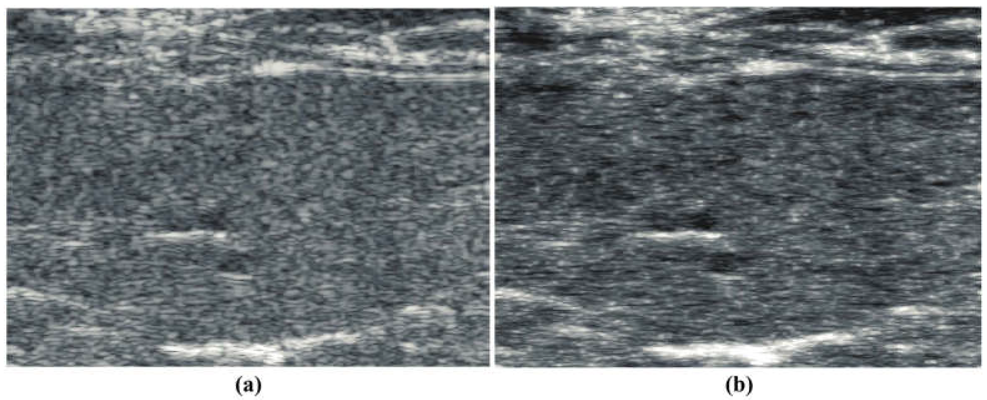
Similarly, a B-scan from a subject on a steatotic diet [19] is shown in Figure 2a, demonstrating the classic general hyperechoic pattern as compared to normals. The corresponding “thru-scan” is shown in Figure 2b. Again, a pattern of possible fluid channels (hypoechoic spaces) along with small hyperechoic foci is seen throughout the background scattering amplitude. Compared with the normal liver’s constrained reconstruction (Figure 1b), the steatotic liver in Figure 2b appears more hyperechoic, and the hyperechoic spots are distributed throughout the liver. The speckle pattern within the liver in Figure 2a from the conventional envelope has a mean/standard deviation ratio of 1.97, close to the theoretical Rayleigh speckle ratio of 1.91 expected from ensembles of subresolved scatterers [1]. In comparison, the constrained power law reconstruction of Figure 2b has a mean/standard deviation ratio of 2.18, indicating a higher value of what Burkhardt termed as the “signal to noise” ratio of speckle patterns [1]. Similar trends are seen in the processing of human livers at 3 MHz, normal vs. steatotic, but these images are not available at this time for distribution, only by request.

5. Discussion and Conclusions

A primary consideration of the reconstructions outlined in this framework is that the resulting image of scatterers (the 2D distribution of the magnitude of R x , z ) is not unique in the sense of a mathematical exact solution to an inverse problem. However, it represents a constrained solution where the constraints are derived from the echo amplitudes and from the theoretical power law distribution of scattering from vascularized tissues. Scattering of ultrasound from soft vascularized tissue is not a white noise process; instead, the nature of a multiscale or fractal distribution of internal structures leads to a power law in scattering [13,20], and this is enforced by filtering in our processing. In practice, we observe a stable rendering of reconstructions by averaging the results from five independent realizations of the random multiplication step. However, the usefulness of this approach outside of soft vascularized tissues, for example, tendons where strong anisotropy or periodicity is present, remains to be evaluated.
Within this framework there is an expansive parameter space that can be explored further. These implementation parameters include the probability distribution of the random multiplication step (we utilized uniformly distributed white noise), the rho filter (our implementation is shown in Appendix A), and any prefiltering steps applied to the envelope prior to use in the algorithm. These parameter choices and trade-offs will influence the final rendition of the reconstruction. However, due to resource constraints, the detailed description of these effects is left for future research. Nonetheless, the examples provided and related studies have shown that an alternative reconstruction process, based on constraints from the received echo envelope and the power law framework, can produce an image that is not dominated by the traditional granular speckle pattern, and may more visibly portray some of the key structural components of tissue parenchyma.

Funding

This research was supported by the National Institutes of Health, grant number R01DK126833.

Data Availability Statement

All data in support of the findings of this paper are available within the article, or by request for the larger RF echo files.

Acknowledgments

The mouse liver scans were obtained from the laboratory of Professor Kenneth Hoyt, and his research is gratefully acknowledged.

Conflicts of Interest

The author declares no conflicts of interest.

Appendix A

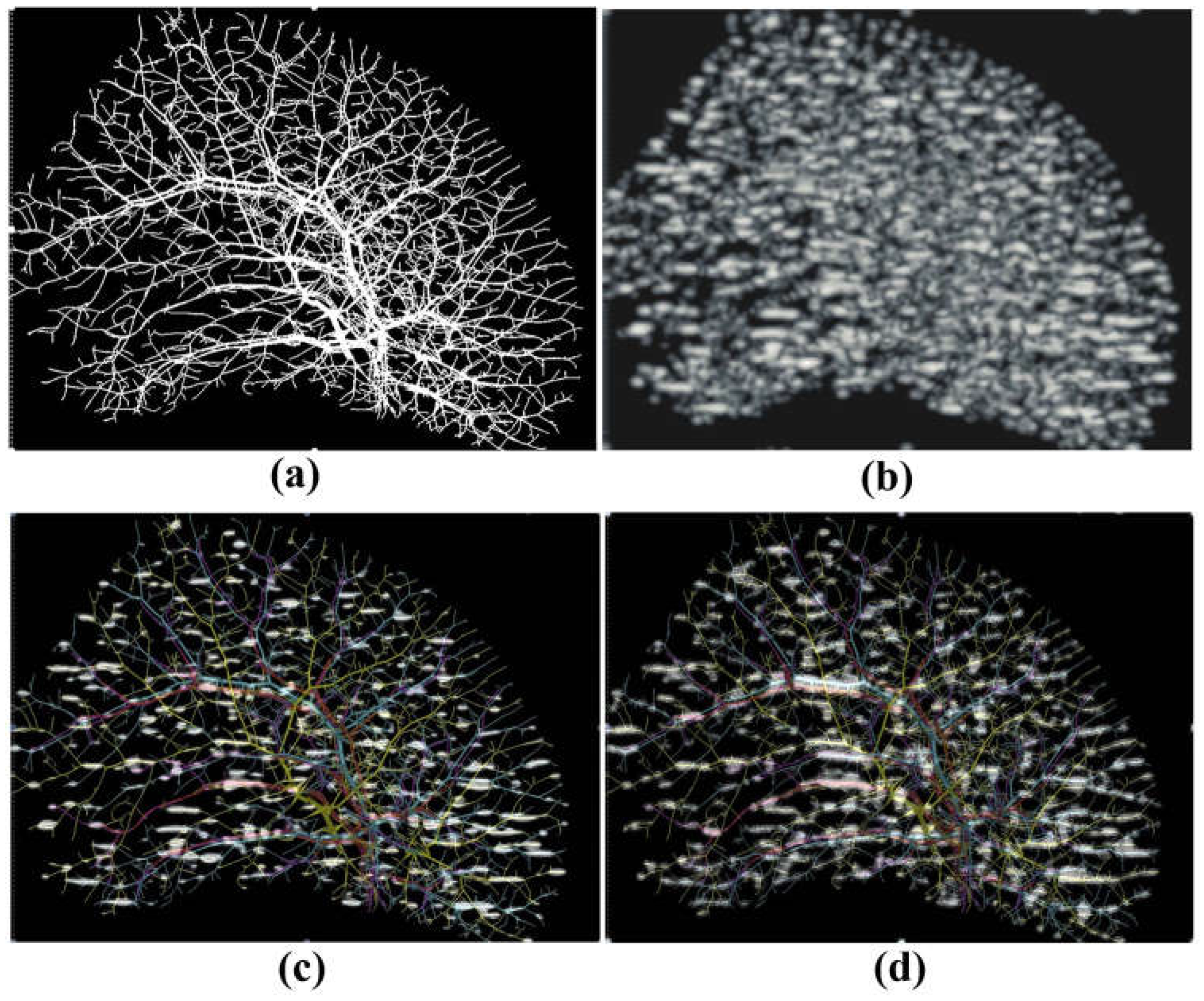
Here, we explored a 2D simulation of the pulse echo model using the hepatic vasculature model in a mouse liver as the dominant scattering structure within the liver and comparing a high-resolution (high-frequency ultrasound) version with the thru-scan version of a low-resolution (low-frequency ultrasound) version. Figure A1 shows (a) the scattering model of the vasculature covering approximately 1.1 × 1.1 cm. This follows the reconstruction of liver vasculature described by Zhang et al. [21] with a thickness projection of 100 μ m. In (b) is the high frequency (approximately 50 microns wavelength and 50% bandwidth pulse-echo envelope, vertical is the axial direction of the pulse echo scan, horizontal is lateral); in (c) is the upper 20% of speckle amplitude (only the maximum quintile amplitudes are shown) co-located over the vascular pattern; and in (d) are the results after lower frequency (approximately 100 microns wavelength) convolution, followed by the thru-scan processing, showing only the upper 20% of echo amplitude, the hyperechoic regions. The high-frequency scan and the power law reconstruction from lower frequencies both produce hyperechoic foci that coincide with strongly reflecting orientation of the structures. When the cylindrical vessels are oriented horizontally, the lateral direction of the scan maximizes the backscatter from that structure [13,22,23].
Figure A1. (a) Scattering structure of vasculature within a liver, represented simply as a binary image with an image scale of approximately 1 cm square. (b) Echo pattern from a high-frequency (wavelength approximately 50 microns) scan, simulated using 2D convolution of a pulse with the binary structure of (a). (c) The top 20% of the amplitudes, the hyperechoic regions (only the top quintile of amplitudes), are superimposed on the vascular tree showing the pattern of high scattering from laterally oriented cylinders. (d) Top 20% of amplitudes of the thru-scan reconstruction from a lower-frequency scan (wavelength approximately 100 microns). The thru-scan reconstruction has numerous hyperechoic areas that correspond to structures highlighted at the 2× higher frequency shown in (c). Vascular tree reproduced with permission [21].
Acoustics 06 00043 g0a1
Furthermore, there is reasonable co-location between the hyperechoic peaks of the high-resolution scan and the power law reconstruction from the lower-frequency, lower-resolution scan. However, the lower-resolution scan evidently includes more regions where a closely located parallel pair of horizontal cylinders were included in the larger pulse at lower frequency, creating a stronger overlapping echo than in the case of the higher-resolution scan. Overall, these simple simulations support the hypothesis that hyperechoic points in thru-scans are plausibly related to strong scatterer orientations within the liver, similar to, but not identical to, all peaks that would be seen from a much-higher-frequency scan of the same tissue.
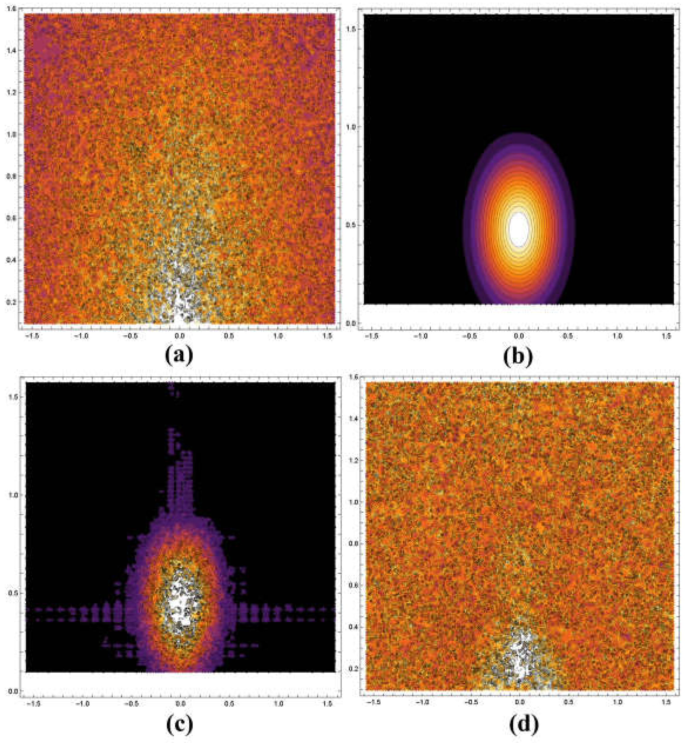
It is instructive to examine the spatial Fourier transform of the process in order to visualize how the spectra are modified during the steps outlined in Section 3. In these examples, the discrete time Fourier transform operation is implemented through the “ListFourierSequenceTransform” routine in Mathematica, and ContourPlot displays are produced, utilizing the log-compressed magnitude and a color scale where dark to light hues represent the minimum to maximum values. The spatial Fourier transform of the binary scattering object of Figure A1 representing the fractal branching vasculature is shown in Figure A2a. In this and following plots, the half plane of the transform space (k-space) is shown, the horizontal scale is the transform of the horizontal axis ( π / 2 to π / 2 ), and the vertical scale represents the transform of the vertical axis of Figure A1a (0 to π / 2 ) in discrete frequency units (the upper half of k-space). Shown in Figure A2a is the spatial transform magnitude of the binary scattering object, which is maximum near the low-frequency origin (0,0 is located at the center of the bottom axis), and generally diminishes as a function of increasing spatial frequency, as would be expected for the Fourier transform of a binary fractal object [20]. Shown in Figure A2b is the transform of the low-frequency pulse described in the previous section. After convolution of the low-frequency pulse with the scattering vasculature, the resulting spectrum of the RF “echo” is shown in Figure A2c. Since convolution in the spatial domain is a multiplication in the transform domain, the support of the RF “echo” has been limited by the pulse, so most of the information contained in the higher spatial frequencies is absent. However, after multiplication of the envelope by random white noise and then “rho” filtering of the scatterers (steps (ii) and (iii) of Section 3), the resulting set of scatterers has a transform, shown in Figure A2d, that more closely resembles the pattern of the original in Figure A2a.
Figure A2. Representation of the half planes of the transform (k-space). The horizontal scale is the transform of the horizontal axes ( π / 2 to π / 2 ), and the vertical scale represents the transform of the vertical axis of Figure A1a (0 to π / 2 ) in discrete frequency units. Zero frequency is located in the middle of the lower horizontal axis in each case, and the color scale for magnitudes is dark to white (the maximum normalized value is shown in white). (a) Magnitude of the spatial Fourier transform of the binary scattering pattern of Figure A1a. (b) Support of the pulse used as the model of the ultrasound pulse echo convolution. (c) Product of (a,b), representing the transform of the RF echo produced by convolution. Comparing (ac), the loss of information across k-space is significant and unrecoverable by traditional means. (d) Transform after the power law constrained reconstruction. This solution is not exact or unique but conforms to the most important constraints, the echo amplitude, and the power law nature of the scattering structures.
Acoustics 06 00043 g0a2
Thus, the processing forms an ersatz solution which approximately conforms to the original envelope and to the general power law behaviors of multiscale scattering structures in tissue. We note that these steps are illustrative of the process but do not represent a complete 3D scattering simulation, which would include scattering theory, including a k 4 weighting of smaller structures (the long wavelength or Rayleigh scattering regime) [20].
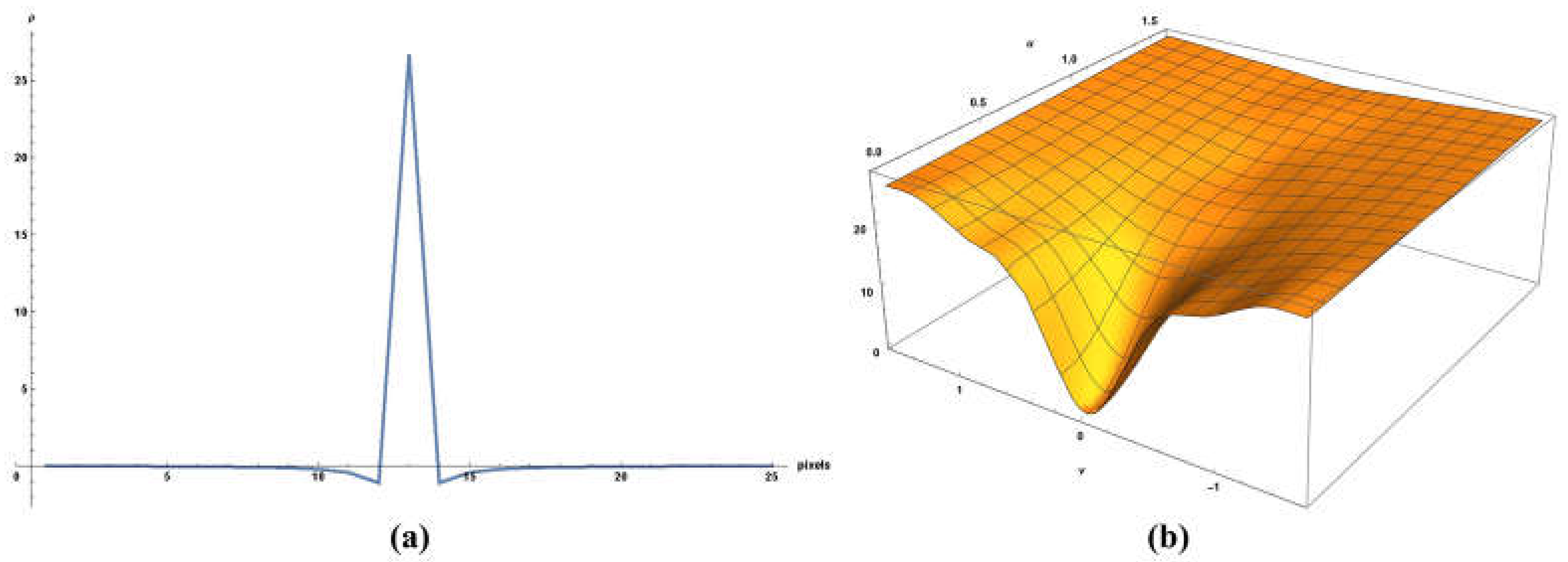
Another important implementation detail is the choice of rho filter (Equation (1) or alternative power law filter for use in the algorithm). Key issues include the spatial sampling rate for use of Equation (1) and avoiding discontinuities and Gibbs phenomenon in the filter response. Our implementation is shown in Figure A3; in (a) is the rho filter as a function of position along the transverse axis (the filter is symmetric in 2D), and in (b) is the magnitude of the discrete time Fourier transform showing the half plane of k-space. Note that this is designed to have zero amplitude at zero frequency and to be increasing from the origin, but then flattens to condition the high frequencies and the periodic replication in discrete frequency space. Final image reconstructions will be affected by the spatial and transform properties; however, a detailed exposition of these is left for future research.
Figure A3. (a) Axis symmetric rho filter along the transverse axis. The filter is implemented as a 2D convolution kernel of 25 × 25 pixels. (b) Magnitude of the discrete time Fourier transform of this 2D filter, showing the half plane of k-space. This filter is designed to enforce a power law behavior on the scatterers and have zero amplitude at zero frequency. To condition the high frequencies and smooth the periodic replication in discrete frequency space, the function flattens at the highest spatial frequencies.
Acoustics 06 00043 g0a3

References

  1. Burckhardt, C.B. Speckle in ultrasound b-mode scans. IEEE Trans. Sonics Ultrason. 1978, 25, 1–6. [Google Scholar] [CrossRef]
  2. Shin, H.C.; Prager, R.; Ng, J.; Gomersall, H.; Kingsbury, N.; Treece, G.; Gee, A. Sensitivity to point-spread function parameters in medical ultrasound image deconvolution. Ultrasonics 2009, 49, 344–357. [Google Scholar] [CrossRef] [PubMed]
  3. Jensen, J.A. Real time deconvolution of in-vivo ultrasound images. In Proceedings of the 2013 IEEE International Ultrasonics Symposium (IUS), Prague, Czech Republic, 21–25 July 2013; pp. 29–32. [Google Scholar]
  4. Chen, S.; Parker, K.J. Enhanced resolution pulse-echo imaging with stabilized pulses. J. Med. Imaging 2016, 3, 027003. [Google Scholar] [CrossRef] [PubMed]
  5. Chen, S.; Parker, K.J. Enhanced axial and lateral resolution using stabilized pulses. J. Med. Imaging 2017, 4, 027001. [Google Scholar] [CrossRef] [PubMed]
  6. Duarte-Salazar, C.A.; Castro-Ospina, A.E.; Becerra, M.A.; Delgado-Trejos, E. Speckle noise reduction in ultrasound images for improving the metrological evaluation of biomedical applications: An overview. IEEE Access 2020, 8, 15983–15999. [Google Scholar] [CrossRef]
  7. Kassab, G.S. Scaling laws of vascular trees: Of form and function. Am. J. Physiol. Heart Circ. Physiol. 2006, 290, H894–903. [Google Scholar] [CrossRef] [PubMed]
  8. Newman, M.E.J. Power laws, Pareto distributions and Zipf’s law. Contemp. Phys. 2005, 46, 323–351. [Google Scholar] [CrossRef]
  9. Parker, K.J. Power laws prevail in medical ultrasound. Phys. Med. Biol. 2022, 67, 09TR02. [Google Scholar] [CrossRef] [PubMed]
  10. Parker, K.J.; Poul, S.S. Burr, Lomax, Pareto, and logistic distributions from ultrasound speckle. Ultrason. Imaging 2020, 42, 203–212. [Google Scholar] [CrossRef] [PubMed]
  11. Waag, R.C.; Lee, P.P.K.; Persson, H.W.; Schenk, E.A.; Gramiak, R. Frequency-dependent angle scattering of ultrasound by liver. J. Acoust. Soc. Am. 1982, 72, 343–352. [Google Scholar] [CrossRef] [PubMed]
  12. Campbell, J.A.; Waag, R.C. Measurements of calf liver ultrasonic differential and total scattering cross sections. J. Acoust. Soc. Am. 1984, 75, 603–611. [Google Scholar] [CrossRef]
  13. Parker, K.J. Shapes and distributions of soft tissue scatterers. Phys. Med. Biol. 2019, 64, 175022. [Google Scholar] [CrossRef] [PubMed]
  14. Doyley, M.M. Model-based elastography: A survey of approaches to the inverse elasticity problem. Phys. Med. Biol. 2012, 57, R35–R73. [Google Scholar] [CrossRef] [PubMed]
  15. Szabo, T.L. Diagnostic Ultrasound Imaging: Inside Out, 2nd ed.; Academic Press: Amsterdam, The Netherlands, 2014. [Google Scholar]
  16. Macovski, A. Basic Ultrasonic Imaging; Prentice-Hall: Englewood Cliffs, NJ, USA, 1983. [Google Scholar]
  17. Prince, J.L.; Links, J.M. Medical Imaging Signals and Systems; Pearson Prentice Hall: Upper Saddle River, NJ, USA, 2006; p. xvi. 480p. [Google Scholar]
  18. Basavarajappa, L.; Li, J.; Tai, H.; Song, J.; Parker, K.J.; Hoyt, K. Early detection of liver steatosis using multiparametric ultrasound imaging. In Proceedings of the 2021 IEEE International Ultrasonics Symposium (IUS), Virtual, 11–16 September 2021; pp. 1–4. [Google Scholar]
  19. Baek, J.; Basavarajappa, L.; Margolis, R.; Arthur, L.; Li, J.; Hoyt, K.; Parker, K.J. Multiparametric ultrasound imaging for early-stage steatosis: Comparison with magnetic resonance imaging-based proton density fat fraction. Med. Phys. 2024, 51, 1313–1325. [Google Scholar] [CrossRef] [PubMed]
  20. Carroll-Nellenback, J.J.; White, R.J.; Wood, R.W.; Parker, K.J. Liver backscatter and the hepatic vasculature’s autocorrelation function. Acoustics 2020, 2, 3–12. [Google Scholar] [CrossRef]
  21. Zhang, Q.; Li, A.; Chen, S.; Yuan, J.; Jiang, T.; Li, X.; Luo, Q.; Feng, Z.; Gong, H. Multiscale reconstruction of various vessels in the intact murine liver lobe. Commun. Biol. 2022, 5, 260. [Google Scholar] [CrossRef] [PubMed]
  22. Faran, J.J., Jr. Sound scattering by solid cylinders and spheres. J. Acoust. Soc. Am. 1951, 23, 405–418. [Google Scholar] [CrossRef]
  23. Stanton, T.K. Sound scattering by cylinders of finite length. II. Elastic cylinders. J. Acoust. Soc. Am. 1988, 83, 64–67. [Google Scholar] [CrossRef]
Figure 1. (a) Conventional B-scan at 15 MHz from a control group rat liver, in vivo. (b) Constrained reconstruction from power law principles, which we call “thru-scan”, demonstrating a modified texture across the liver interior and the emergence of specific hyperechoic points, many of which appear coincident with the local maxima of the original envelope. The images are displayed conventionally using log-compressed 50 dB dynamic range grayscale.
Acoustics 06 00043 g001
Figure 2. (a) Conventional B-scan at 15 MHz from a diet-induced steatotic mouse liver, in vivo. (b) constrained reconstruction from power law principles, which we call “thru-scan”, demonstrating a modified background and the emergence of specific hyperechoic points. The images are displayed conventionally using log-compressed 50 dB dynamic range grayscale.
Acoustics 06 00043 g002
Table 1. Notation for key waveforms and measures.
ParameterDefinitionAdditional Information
e t Analytic envelope of the received signal R ^ t = 2 z / c
I t IntensitySpecified here as the square of the analytic envelope.
P 2 f Power spectrum of p t Specified here as F p t 2 , where F   is the Fourier transform operator.
R t   o r   z Reflection coefficientUnknown at high resolution and is the object of our constrained reconstruction. In the theory of multiscale weak scattering, R is distributed as a zero-mean random variable with a magnitude described by the power law (Pareto) distribution, so the ultrasound pulse will encounter few strong scatterers and many smaller weaker scatterers according to a power law.
N R I Histogram of intensity of the echoesIn theory approaching a Lomax distribution, or concurrently, a Burr distribution for amplitude.
R R z Autocorrelation function of the reflections R z In theory approaching a power law function.
R 2 f Power spectrum of the scatterers R t In theory and from scattering experiments the ensemble average approaches a power law function of frequency.
Disclaimer/Publisher’s Note: The statements, opinions and data contained in all publications are solely those of the individual author(s) and contributor(s) and not of MDPI and/or the editor(s). MDPI and/or the editor(s) disclaim responsibility for any injury to people or property resulting from any ideas, methods, instructions or products referred to in the content.