Article

Tractor Three-Point Hitch Control for an Independent Lower Arms System

Zimeno Inc., dba Monarch Tractor, 203 Lawrence Dr Suite A, Livermore, CA 94551, USA
*
Author to whom correspondence should be addressed.
AgriEngineering 2024, 6(2), 1725-1746; https://doi.org/10.3390/agriengineering6020100
Submission received: 10 May 2024 / Revised: 10 June 2024 / Accepted: 12 June 2024 / Published: 14 June 2024
(This article belongs to the Section Agricultural Mechanization and Machinery)

Abstract

:
The three-point hitch, found on agricultural tractors, facilitates the raising and lowering of an attached implement. Some tractors include a rock shaft that comprises a physical shaft that interconnects and facilitates the raising and lowering of the lower arms of the three-point hitch in a synchronized manner. In this study, we deal with a hitch system with the lower arms actuated by two independent hydraulic cylinders. This innovative tractor hitch system design allows the implement to follow the terrain, instead of the tractor, about the fore–aft (roll) axis of the tractor. However, since the two lower arms are independent, a specialized controller is needed to move these arms in unison. First, we present a position controller for individual arms and a roll controller to move these arms together. Second, we present a unique algorithm to emulate a physical rock shaft while the implement is operating in float mode. The algorithm ensures that the implement does not roll around the fore–aft axis while making sure it moves up and down vertically to follow the terrain. We present experimental results from the step response of the hitch system’s height while tracking a velocity reference. With the roll of the implement defined as the difference between the left arm’s position in percentage and that of the right arm in percentage, we observe that the largest mean roll was 0.23% with a flail mower attached and 0.26% without any implement. We then present results from the implement’s position in the float mode when the software rock shaft was activated and compare them with the case without the software rock shaft. The experiments showed that, when the software rock shaft was turned on, the mean roll reduced from 4.64% to 0.58% with a seed drill implement and from −3.99% to −0.59% with a flail mower implement. The standard deviations in these two implement cases improved from 16.77% to 2.79% and 6.45% to 3.53%, respectively, proving the effectiveness of the software rock shaft and its potential to replace the physical rock shaft found on the traditional tractors.

1. Introduction

The three-point hitch system plays a vital role in agricultural tractors. It attaches external implements to the tractor to carry out various operations, such as disking, mowing, spraying, etc. Standard-sized implements should attach to any three-point hitch system available on the tractor. Significant efforts are devoted to improving the tractor’s functioning by increasing the efficiency of various operations performed by it. Some of these improvements include re-designing the tractor propulsion system, such as electrification, or introducing more by-wire technologies for various hydraulic operations. By-wire technologies play a vital role in the future of farming with human-optional or autonomous tractors.
High-voltage electrification of tractors has become an active area of research [1,2,3]. A prototype for a small electric tractor was developed by remodeling an internal combustion engine tractor in [4]. The performance of a hybrid tractor was analyzed and compared with a traditional tractor in [5]. A similar study and analysis were conducted in [6]. Also, there have been efforts towards developing autonomous tractors in recent times [7]. The tractor used in this study, the Monarch Tractor model MK-V, is fully electric and driver-optional, i.e., optionally autonomous [8].
Due to the electrification of the tractor, hydraulic flow is generated by a pump attached to an electric motor instead of an engine. Microcontroller-based electronic control units (ECUs), which replaced traditional hydro-mechanical systems, are vital in controlling three-point hitch systems [9]. A recent study on a tractor implement performance mapping [10] presents a novel embedded system using a microcontroller, load cells, hall sensors, and a global positioning system (GPS). The design and development of electro-hydraulic systems for hitch control for tractors has been an active area of research [11,12,13].
To improve the performance of various operations carried out by a hitch, some research has been devoted to estimating implement attitudes. A recent study on a novel rolling angle estimation algorithm [2] shows the potential for improving the implement roll control. The authors in [2] used a hydraulic cylinder on one of the two hitch lower arms to control the roll. These hydraulic cylinders are usually installed on only one arm as an accessory. Without this accessory, operators use a locknut-style arm to manually rotate and change the roll of the implement, which is involved and cannot be carried out in real time during the driving operation. A microcontroller-based embedded technology is widely used in tractors for efficiently and accurately measuring vital tractor parameters such as wheel slippage, PTO torque, implement attitude, etc. [2,14,15]. As there have been improvements in parameter measurements and estimations, research also exists on performance improvements using more sophisticated controllers in tractors [16]. The authors in [16] improved the tractor implement’s motion control using the feedback from the front axle.
With increased reliance on microcontroller-based technology to control various operations in tractors, it is important to develop the controllers and logic that emulate the replaced mechanical hardware. For example, as the mechanical connections between the hydraulic valves and the hitch operation lever are removed, it was crucial to emulate the effect of the lever on the hitch movement [9]. Standard closed-loop controllers such as proportional-integral-derivative (PID) controllers are commonly used in various tractor control systems. A PID controller was used to improve the dynamic stability of a tractor in [17], to devise target-tracking and trajectory-planning in [18], and to reduce vibrations in the tractor in [19]. While various controllers similar to those mentioned above are also used on the Monarch Tractor’s MK-V platform, we focus on using a closed-loop PID controller for electro-hydraulic hitch system control in this study. Similar feedback-based control systems on conventional tractor hitch systems are thoroughly reviewed in [20]. The authors in [21] designed a fuzzy-PID adaptive controller for an electro-hydraulic hitch system. Many studies have been devoted to the control of hydraulic cylinders for improved position accuracy, some of which have been summarized in [22]. We have developed a control system based on the approach reported by [23,24] for position and velocity controllers for hydraulic systems.
Traditionally, the two lower arms of the three-point hitch system are attached to a physical rock shaft and actuated by a single hydraulic cylinder, and as a result, they move up and down together [25]. However, in this application, we use a system where two different cylinders actuate these two lower arms. This is discussed in detail in the following sections. Our innovative approach of using independent cylinders for each lower arm of the hitch system brings forth a host of unique benefits. Since we can use the independent cylinders to control the implement freely, we define the implement’s attitude as follows: the roll is the rotation about the fore–aft axis passing through the tractor, the pitch is the rotation about a lateral/sideways axis, and the yaw is the rotation about the vertical axis. The coordinate system is defined in Figure 1. This study focuses on the roll of the implement, and we keep the pitch control for future studies. The development of a yaw controller for the implement is considered out of the scope of this study. The unique benefits provided by the use of independent cylinders to the tractor operators and to the design of the tractor can be summarized as follows:
  • Roll control without any accessory: Independent cylinders on each arm of the tractor provide easy control of the roll of the implement without requiring an extra adjustment arm on the implement. For example, in the case of a box scraper [26], the operators can easily choose an implement without the hydraulic cylinder that would have been used for adjustment of the implement roll. The tractor can save the configuration for the hitch height as well as the roll angle and also allows the operators to actuate the implement with these parameters in real time.
  • Modularity and Serviceability: Using two independent cylinders, we took a modular approach since each set of cylinders and lower arms in one module is independent of the other. This facilitates better serviceability, which can include repairing or replacing existing components.
  • Packaging: Without the rock shaft assembly, the packaging in the tractor becomes less complex, and it saves space for other components and accessories.
  • Cost reduction: By removing the physical rock shaft assembly, we were able to simplify the mechanical design and reduce material costs.
  • Ease of attaching implements: Since the arms can be moved up and down independently, it is easy to attach an implement to the three-point hitch system. Also, the architecture of the hydraulics in MK-V tractors allows individual cylinders to float independently, which makes it easy to move each cylinder without any hydraulic assistance while attaching implements [27].
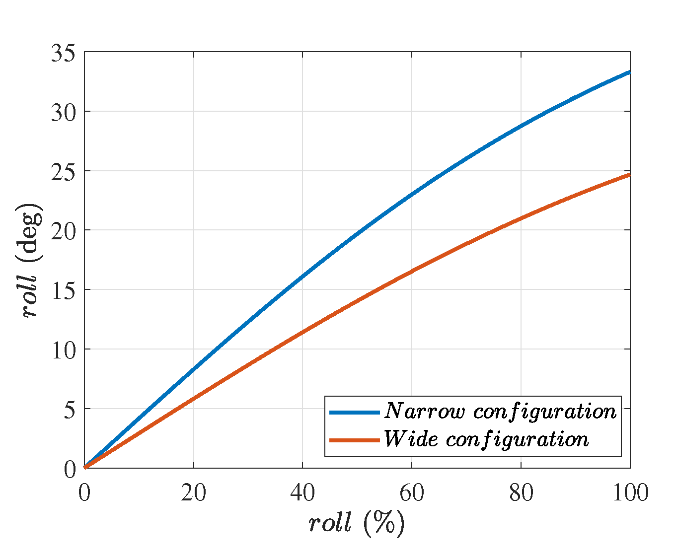
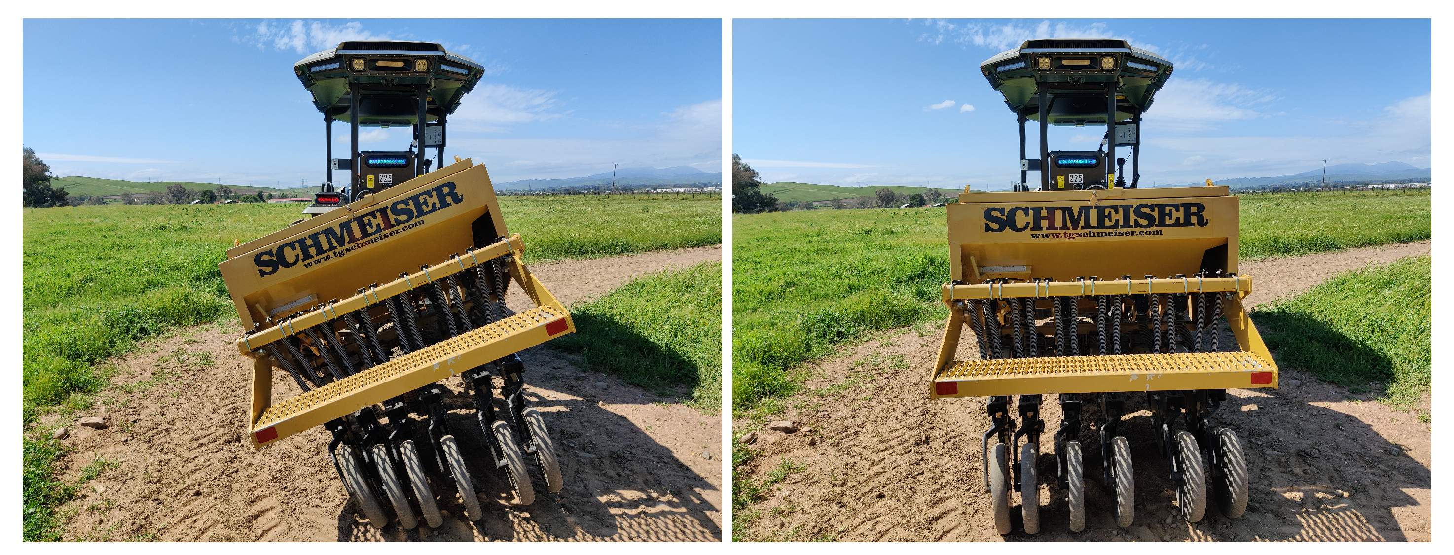
  • Extreme roll: In traditional tractors, solid links are used for three-point hitch lower arms, which can move together because of the physical constraints imposed by the rock shaft. In some implementations, one of these arms is replaced with a hydraulic cylinder [2], which can be actuated to achieve roll in the implement. However, the amount of roll is limited due to the limited stroke length of the add-on cylinder, whereas, in our case, a significantly large amount of roll can be achieved. An extreme roll angle is achieved when one cylinder is fully retracted, and the other is fully extended.
While the hitch’s design with two independent cylinders for lower arms has benefits, emulating the effect of a physical rock shaft is challenging. We list those challenges and their potential solutions below.
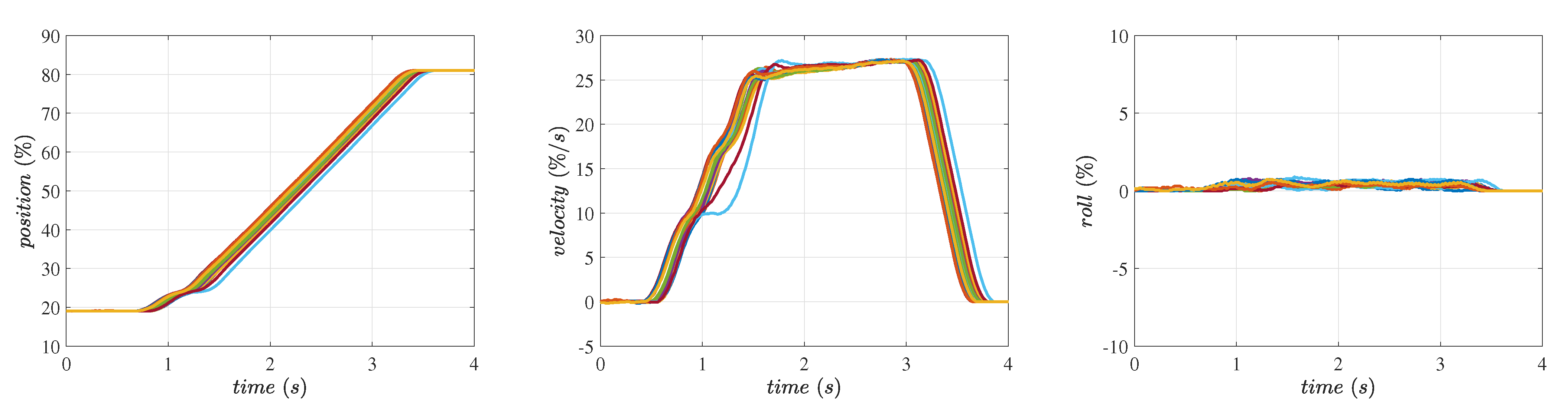
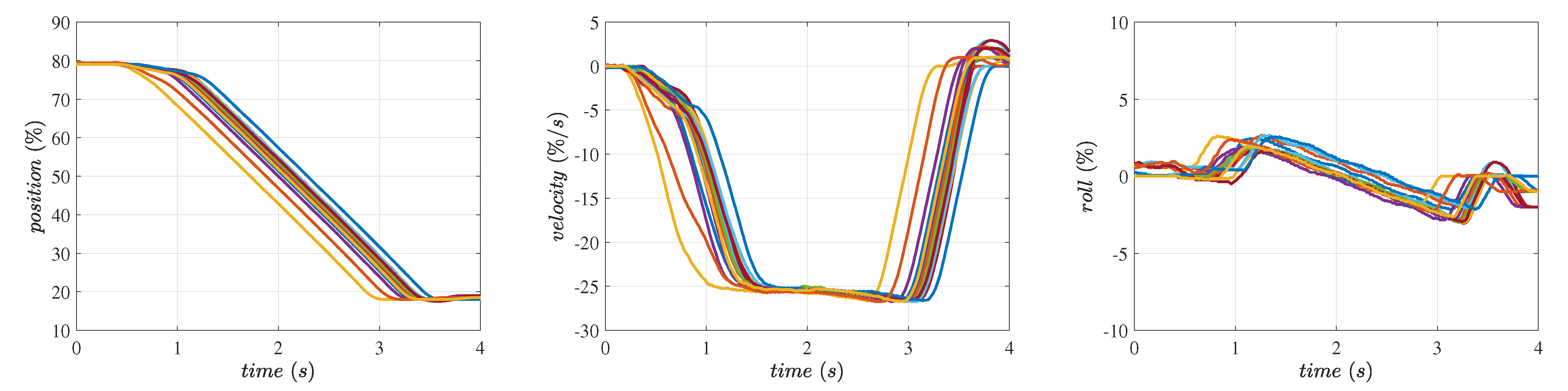
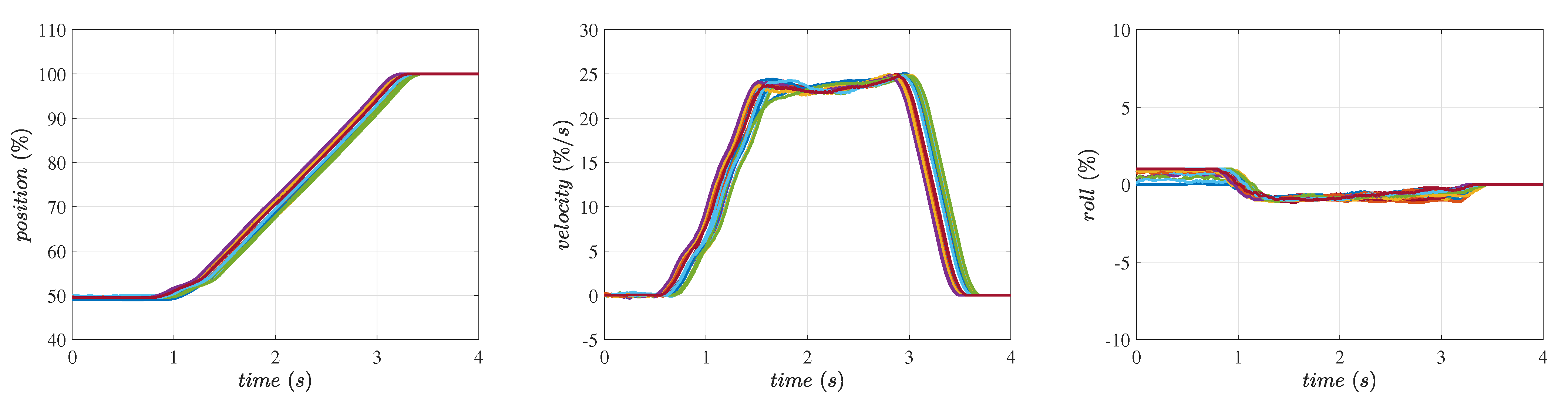
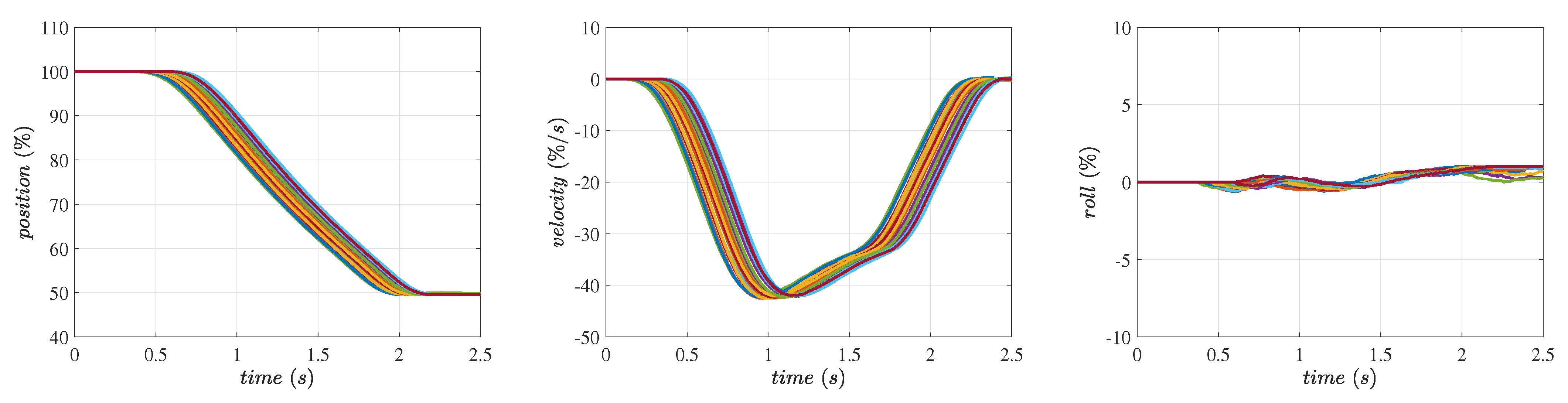
  • Position control: It is often necessary to control the position of the implements in the vertical direction without any roll with respect to the tractor. This basic requirement leads to a challenge as it demands the arms to move up and down in a synchronized manner. We have introduced the roll control algorithm that is coupled with the position control algorithm for the hitch height motion. We have conducted experiments that exhibit the performance of the position control algorithm through step responses.
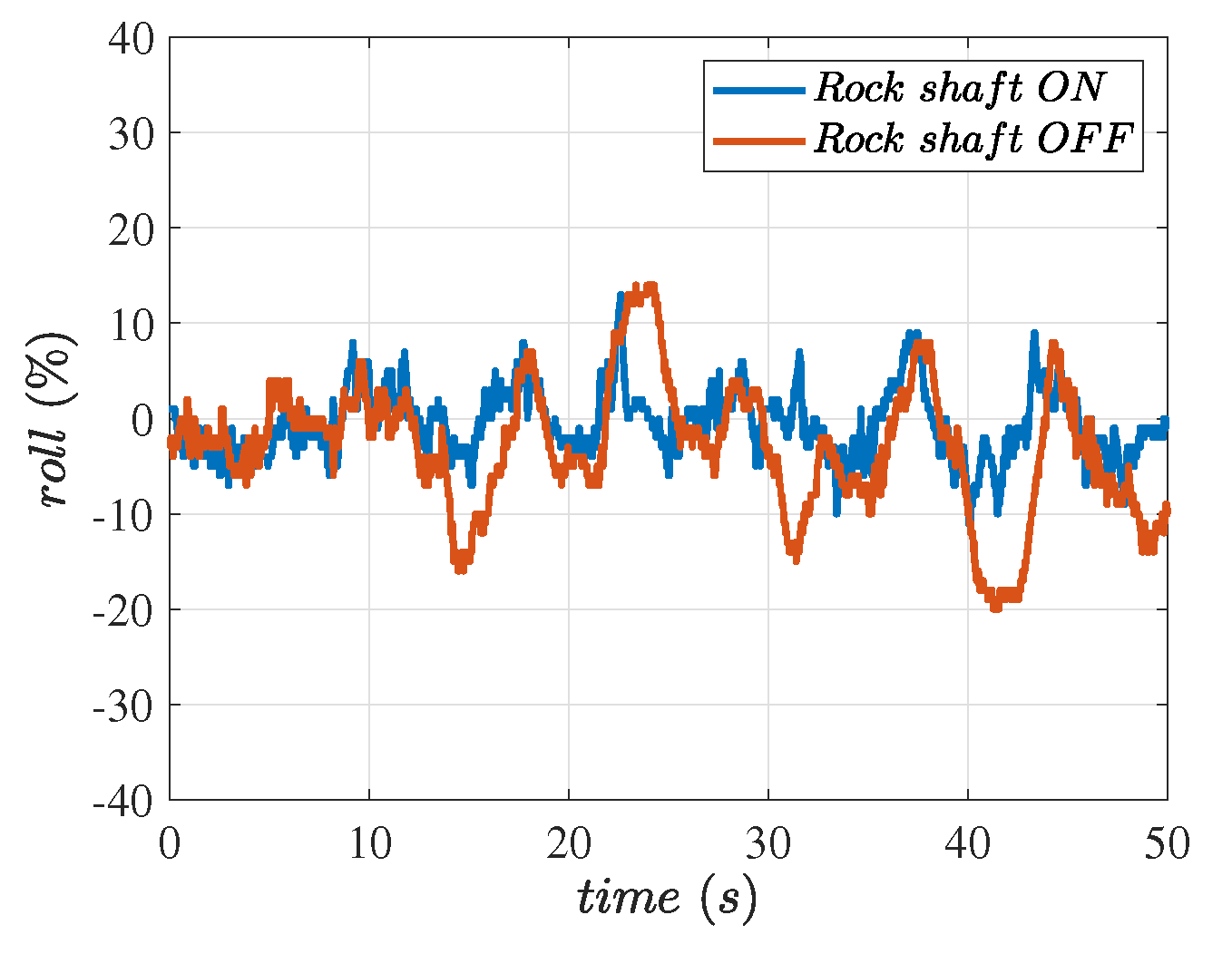
  • Follow the terrain around the roll axis: The hitch system allows the implement to follow the terrain, instead of the tractor, around the roll axis when in float mode. However, if we need the implement to follow the tractor, it is often not feasible without a rock shaft. The importance of implements following the terrain while in float mode is thoroughly explained in [28,29,30]. This motivates our work on a software rock shaft, which we discuss in detail in the following sections and show results from the experiments. The algorithm ensures that the implement does not rotate around the roll axis while making sure it moves up and down to follow the terrain along that axis of the tractor’s motion.
  • Additional actuators and sensors: Since the lower arm cylinders are independent, two sets of actuators and sensors are required to actuate the cylinders and track their positions, as opposed to one actuator and one sensor on traditional tractors. Although an advantage of having a sensor on each arm is the ability to detect a multitude of cases of sensor failures, which is not possible with just one sensor, it adds additional computational load on the controller.
To summarize the contribution briefly mentioned above, this paper deals with the aforementioned challenges by first introducing a novel position controller with velocity reference. This position controller utilizes a supervisory roll controller to maintain zero roll while reaching the target position. Secondly, we present a software rock shaft algorithm, a key component in resolving the issue of the lower arms following the terrain instead of the tractor’s orientation in the system’s float mode. The goal of this study is to develop and implement a software algorithm that can emulate a physical rock shaft present on traditional tractors. We performed experiments with the proposed controllers, measured the implement’s roll with respect to the tractor, and proved the effectiveness of the software rock shaft and its potential to replace physical rock shafts.
The rest of the paper is organized as follows. We introduce the three-point hitch platform in Section 2. In Section 3, we present the design of the control strategy for the three-point hitch system with two independent lower arms. In Section 4, we describe the methodology used to conduct experiments. In Section 5, we present the results from implementing the position control and software rock shaft on the Monarch Tractor MK-V hitch system and we discuss their significance. In Section 6, we summarize the contribution of the study and list down the future directions.

2. Hardware

2.1. Mechanical Platform

The three-point hitch system of the Monarch Tractor’s MK-V platform is shown in Figure 1. It consists of one hydraulic top link cylinder and two independently controlled hydraulic cylinders for lower arms. The top link plays an important role in adapting to the attached implement’s geometry and keeping the pitch of the implement at a particular angle. Unlike traditional solid top links, which are spun by hand to adjust their length, the MK-V top link is hydraulically actuated by joystick commands. In this study, the length of the top link was predetermined, and the cylinder motion was hydraulically locked.
The lower arms are attached to the lower side of the implements. They are hydraulically actuated with the help of two independent cylinders to lower or raise the implements. The two actuators used on this platform are double-acting hydraulic cylinders, that is, each cylinder has ports on both ends to supply pressurized hydraulic fluid to retract or extend the piston. The hydraulic flow to these cylinders is generated with the help of a variable displacement pump that is driven by an AC motor. The AC motor is also used to drive the electric tractor and to supply power to other systems, such as Power Take-Off (PTO). This paper focuses on the control strategies for the motion of the lower arms.

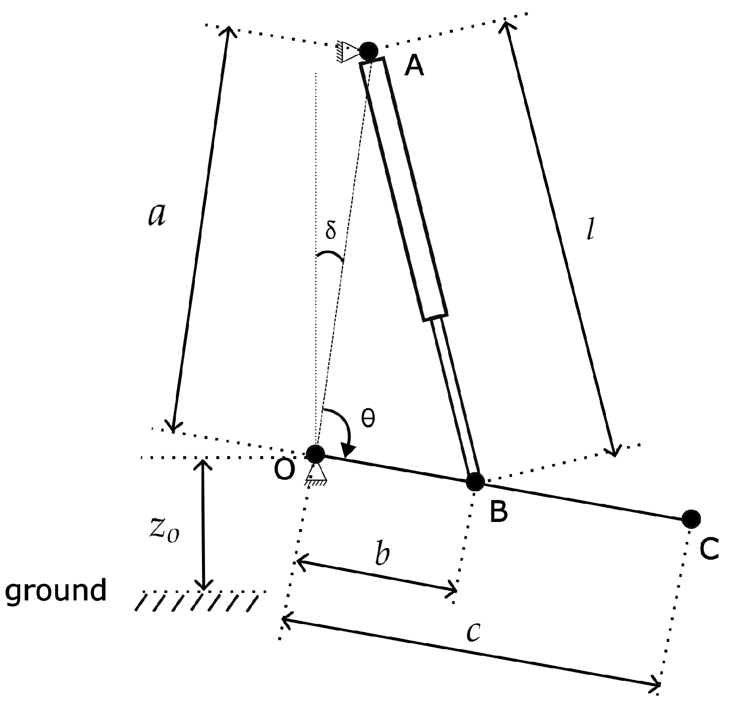
2.2. Geometry of the Actuator

Figure 2 shows the schematic of the side-view of one of the hitch arms, highlighting the involved geometry. The length of the hydraulic cylinder governs the movement of the hitch arm, O C , about point O. The lift point C is where the implement becomes attached to the lower arm of the hitch. It moves up and down as the hydraulic cylinder retracts and extends, respectively. Points A and B are where the cylinder connects to the tractor chassis and hitch arm, respectively. Lengths of segments O A , O B , O C , and A B are denoted by a , b , c , and l, respectively. The length l varies as the cylinder retracts or extends. The angle between the tractor’s frame and hitch arm is defined by A O B in Figure 2 and denoted by θ , and the segment O A makes an angle δ with the vertical. Let z o be the height of the pivot point O of the arm from the ground; then, the height of the lift point, C, from the ground ( z l p ) is given by,
z l p = z o + c c o s ( θ + δ )
Since the lengths a and b are fixed, we can obtain θ as a function of the length of the hydraulic cylinder l using the law of cosines as below,
θ = c o s 1 b 2 + a 2 l 2 2 b a
Using Equations (1) and (2), we can plot the height, z l p , of the lift point C with respect to the range of motion of θ , and cylinder length l. The values of the geometry parameters are listed in Table 1. Figure 3 shows that the height of the lift point ( z l p ) varies approximately linearly with both θ and cylinder length. The motion of the lift point represented by θ is linearly mapped to 0–100%, where 0% and 100% correspond to the lowest and highest positions of the lift point, respectively.

2.3. Actuation and Sensing

We use proportional valves actuated with electromagnetic solenoids to send flow to either side of the hydraulic cylinders. As mentioned in Section 2.1, since we use double-acting hydraulic cylinders, we have separate solenoid valves to control the extension and retraction of the pistons, which correspond to the lowering and raising of the arms, respectively.
The lower arms shown in Figure 2 rotate around their own pivot points, traversing an arc. Using a potentiometer to determine the vertical position of the implement has been a common practice in agricultural engineering [31,32,33]. However, a recent study [34] proved the effectiveness of contactless position sensors for the hitch. We use two hall-effect angle sensors (Novotechnik, Novohall 120 ° Rotary Sensors [35]), which are placed at the two pivot points to measure the angle of the arms, θ . For the feedback to the operator, the full travel of each arm from extreme bottom to extreme top corresponds to 0–100%. Please note here that due to the geometry of the hitch system, 0–100% on the hitch travel does not translate linearly to the height of the implement from the ground, but the relationship is approximately linear as demonstrated in Figure 3. These approximately linear relationships are important for the development of a closed-loop controller of the hitch position, since the position feedback through θ maps linearly with the cylinder length l, which is the direct effect of the actuation. To send flow to either side of the cylinder, we used Hydac proportional valves [36].
In addition to angle sensors at the pivot points of the lower arms, the system includes four Hydac Electronic pressure sensors [37], one for each side of two lower arm cylinders. These four sensors measure pressures on the retract and extend sides of both cylinders. We use these sensors and the geometry of the hitch system to estimate the load on the lower arms. These load estimates play a vital role in the software rock shaft algorithm described in Section 3.3.

2.4. Embedded Microcontroller

The controller used on MK-V is Hydac’s HY-TTC-580 [38], which builds on TI’s 16/32-bit TMS570 microcontroller. The TMS570 series integrates the ARM Cortex-R5F floating-point CPU. Once the algorithm is deployed on the controller, it sends out Pulse-Width Modulated (PWM) signals to actuate the hydraulic valves according to the control logic described in Section 4. The controller’s interface with the position and pressure sensors is implemented over its analog input pins.

3. Controller Design

In this section, we present the design of the software algorithm developed in MATLAB Simulink 2023a for controlling the hitch system presented in the earlier sections. First, we start with the details of the hydraulic cylinders and the hydraulic flow required to actuate them. We then follow up with the system’s position control architecture. Finally, we present the software rock shaft algorithm that mimics the performance of the physical rock shaft found on traditional tractors.

3.1. Plant and Its Actuation

One of the two double-acting cylinders for lower arms in the MK-V hitch system is shown in Figure 4. The extend enable valve and the retract enable valve need to be opened to allow flow to or from the respective port of the cylinder. As these are proportional valves, they can be controlled to allow varying amounts of flow and are controlled by the controller designed in Section 3.2. The extend pressure tank valve and the retract pressure tank valve decide the direction of the cylinder’s motion. To make the cylinder extend, the extend pressure tank valve’s solenoid is energized to connect the pressure line to the extend port (top) of the cylinder, while the retract pressure tank valve’s solenoid is kept de-energized to connect the retract port (bottom) of the cylinder to tank and vice versa for retraction. The flow on the pressure line is generated with the help of a variable displacement pump. To allow the cylinder to float, both the pressure tank valves’ solenoids are kept de-energized while both the enable valves are fully energized to connect both the cylinder ports to the tank.
In this open-loop control system, the controller requests a particular amount of flow to drive the hydraulic actuator at a particular velocity and actuates the valves accordingly. This open-loop control system can move the hitch at a desired velocity only when there is no variation in the identified system’s dynamics. However, in the hitch system, these dynamics vary significantly because of the implement’s weight, geometry, and the location of its center of mass. In the simple case of the arms’ downward motion, the open-loop controller can satisfy the velocity requirement; however, the same open-loop gains would contribute to the hitch system slamming down on the ground if a heavy implement is attached. In fact, in the case of a heavy implement moving down, there is little need for flow as gravity can assist the implement in moving down. Furthermore, valve actuation also needs to be modulated to control the velocity of the implement. This leads to the motivation of a closed-loop position controller, which is described in detail in Section 3.2.
First, we present closed-loop control for controlling the position of each arm. We used a position-velocity cascaded controller instead of a traditional position feedback controller for one major reason—a traditional position controller does not guarantee the cylinder will follow a velocity reference, which is essential, especially when carrying a heavy implement. Also, agricultural tractors traditionally have provided various speed settings for operating the hitch to let the operator control the speed depending on the hitch load. A cascaded position-velocity closed-loop controller has been shown to be effective for controlling hydraulic actuators in [39]. Considering the arm’s desired position as the set point, we designed a controller as shown in Figure 5. The outer loop acts on the error in the position, whereas the inner loop acts on the error in the velocity of the arms. The output of the position PID controller block goes into a velocity saturation block, which considers the desired maximum velocity as the velocity reference for the settings entered by the operator. The output of the velocity saturation block acts as the velocity set point for the arms, and the error in velocity is the difference between this set point and the velocity feedback. The velocity error acts as the input to the velocity PID controller block, which outputs actuation commands for the pump swash plate angle and the hydraulic valve openings. The pump displacement, in combination with the valve openings, moves the cylinder in the desired direction with the desired velocity.

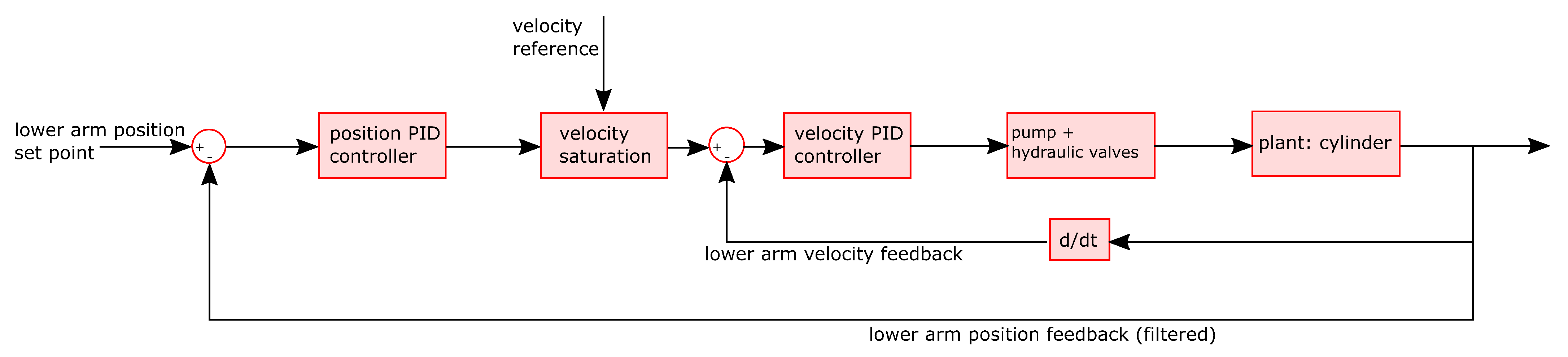
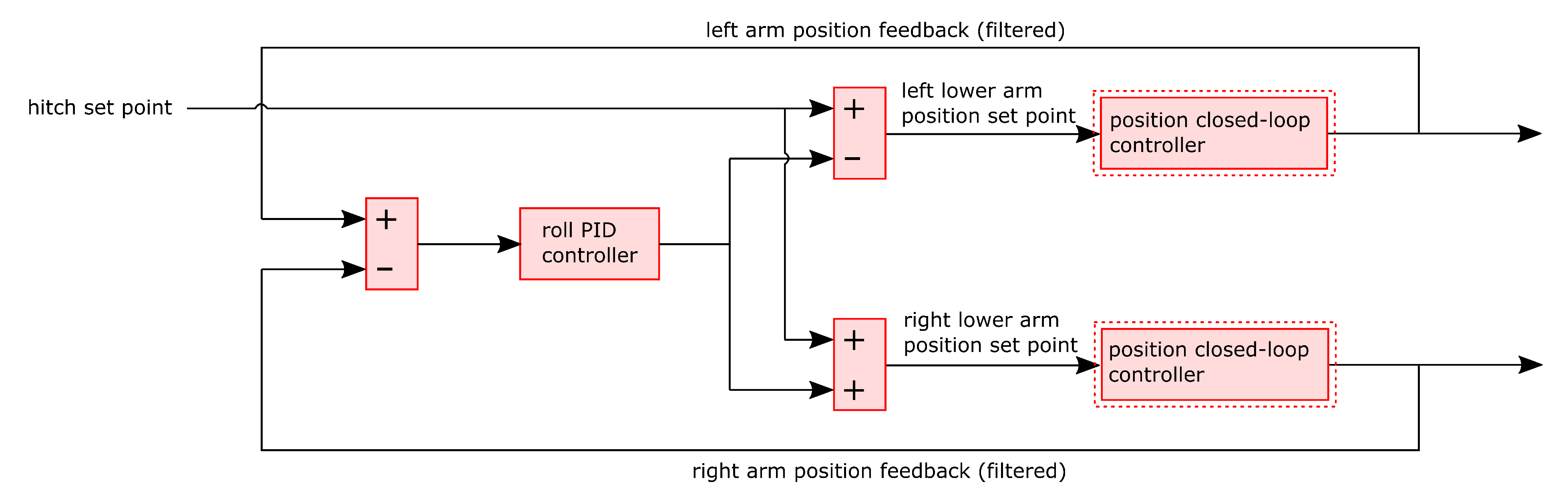
3.2. Closed-Loop Hitch Position Control

The hitch position control system requires both arms to follow a position trajectory in a synchronized manner. However, due to variations in the load on these arms as well as the limitations of the individual closed-loop position controllers, the two arms can often become out of sync. As a reason, it is important to include a roll controller that converges the roll to zero. We define roll, in this case, as the difference between the left arm position and the right arm position. This combined controller, which controls the three-point hitch system, is shown in the form of a block diagram in Figure 6, and it includes the position controller from Figure 5 (shown with dashed boxes in Figure 6).
In an ideal case of no roll in the implement, the individual position controllers for the lower arms would work according to the system’s set point for the hitch height. However, let us consider the cases that the roll controller can address. We consider the cases that the roll controller addresses. When the hitch system is commanded to go up, and the left arm is higher than the right, the roll is positive according to our defined convention. The roll PID controller, with a dominating proportional gain, acts on this positive value to output a processed positive value, which is negated from the left arm position controller’s set point and added to that of the right arm. This supervisory roll controller then helps the left arm to slow down and the right one to speed up while working towards attaining a zero-roll situation. Similarly, the roll controller addresses the cases of negative rolls and also ones when the hitch is commanded to go down, and it poses a non-zero roll situation.

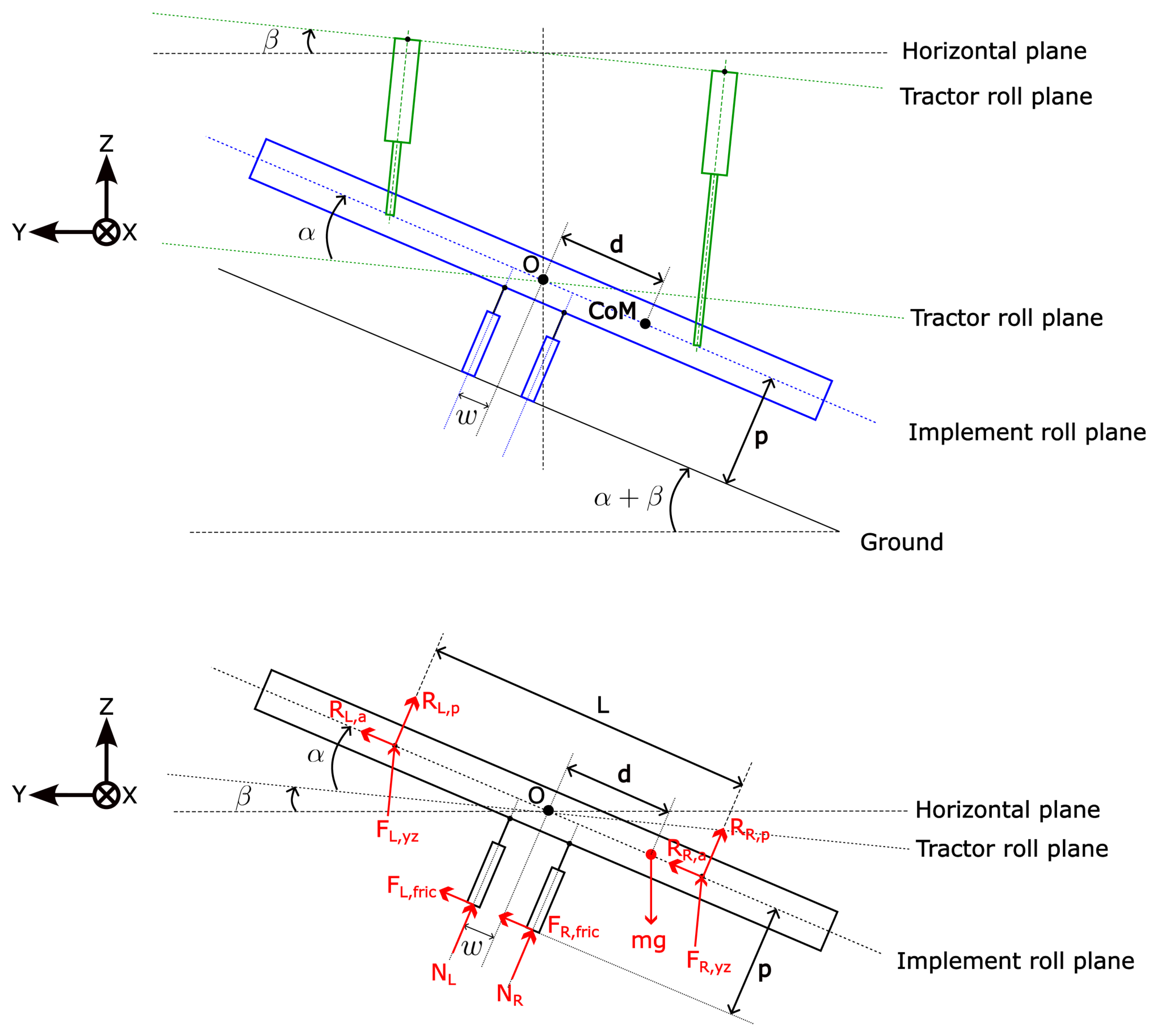
3.3. Software Rock Shaft Algorithm for Float Mode

The hitch system’s position controller uses a supervisory roll controller due to the absence of a physical rock shaft. Similarly, we need to have a sophisticated strategy in the float mode to maintain a zero-roll situation for the hitch with respect to the tractor. In this mode, the implement is expected to float on the ground and follow the terrain while keeping its roll angle relative to the tractor zero. In other words, with this strategy, the implement is expected to not rotate around the roll axis while making sure it moves up and down to follow the terrain along that axis. The hydraulic architecture in the MK-V tractor allows both extend and retract ports shown in Figure 4 to connect to the hydraulic tank. When this feature is used to float the implement, it tends to tilt (roll) as per the terrain profile. This is undesirable for two reasons: it might cause the implement and tractor to become dynamically unstable about the roll axis, and a large implement roll with respect to the tractor will lead to mechanical stress on the implement. This can be avoided by emulating the effects of a physical rock shaft in software.
Figure 7 (top) shows the rear view of an implement connected to the three-point hitch while the tractor moves on uneven terrain, and Figure 7 (bottom) shows its free body diagram. As shown in the figure, an implement of mass m has its center of mass off the center by a distance d, and it has rolled by an angle of α with respect to the tractor, which itself has rolled by an angle of β with respect to horizontal. The two mount points on the implement are separated by a distance L, which is affected by α and the mechanical backlash in the system. F L , y z and F R , y z are the components of the hydraulic force applied by the left and right cylinders, respectively, in the YZ plane, and they are perpendicular to the tractor’s roll plane. The reaction forces from the implement’s mount points to the left and right cylinders are R L and R R , respectively, and they are divided into components along the implement’s roll plane ( R L , a , R R , a ) and perpendicular to it ( R L , p , R R , p ). For the analysis, we consider an implement with wheels that make contact with the ground at a vertical distance of p from the implement’s plane and are connected to the implement at a distance w from the center. They experience normal reactions N L and N R and frictional forces F L , f r i c and F R , f r i c . Assuming J as the moment of inertia of the implement, C as the damping coefficient of the system, which arises due to hydraulic damping in the cylinders and due to the implement tires, and k as the stiffness of the system, which manifests due to the strain on the implement, the dynamic equation for the implement’s roll motion can be written by calculating the moment about the center point O:
J α ¨ + C α ˙ + k α = m g d cos ( α + β ) + ( F L , y z F R , y z ) L 2 cos α                                                                                                                                                                                               + ( R L , p R R , p ) L 2 + ( N L N R ) w + ( F L , f r i c + F R , f r i c ) p
If both the arms are allowed to float independently, the hydraulic forces applied by the cylinders ( F L , y z and F R , y z ) can be assumed to be zero. So, the dynamic equation is simplified to
J α ¨ + C α ˙ + k α = m g d cos ( α + β ) + ( R L , p R R , p ) L 2 + ( N L N R ) w + ( F L , f r i c + F R , f r i c ) p
In Equation (4), m, d, w, and p can vary based on the attached implement. Furthermore, N L , N R , R L , p and R R , p change dynamically. Only the reaction forces R R , p and N R can balance out the rest of the positive terms in the equation to stop an uncontrollable roll. Furthermore, even in the static case of balanced forces, the roll angle can be significant, leading to mechanical strain on the implement. The mechanical strain on the implement in the longitudinal direction increases with the implement’s roll. In the absence of mechanical backlash in the hitch system and the implement, this can be calculated from the geometry in Figure 7 (top) as:
ϵ = L L cos α L cos α = sec α 1
In Equation (3), F L , y z and F R , y z are forces that can be applied by the control system to actively control the roll of the implement. In the scenario shown in Figure 7, F R , y z can help correct the roll of the implement by commanding the right arm to climb up to the left arm’s current position, and by commanding the left arm to stay in float mode ( F L , y z = 0 ) the implement can maintain contact with the ground (Equation (3)). We use these insights to design an active controller that can keep the implement in contact with the ground while correcting the roll of the implement with respect to the tractor (Algorithm 1). To determine when the implement is on the ground, we make use of the pressure sensors in the cylinders to estimate the force on the arms. When the implement is in the air, there is a downward force on the arms due to gravity. However, the downward force vanishes, and an upward force is detected when the implement rests on the ground. Depending on the terrain profile, upward force can be detected on one arm before the other. We use this force detection method, along with the position feedback, to devise an active method to emulate physical rock shafts.
The hitch’s control mode can be flexibly switched between position control or float at any given time based on operator input. Once the operator selects float mode, we initiate the software rock shaft algorithm, as illustrated in Algorithm 1. The algorithm minimizes the implement’s rotation around the roll axis while making sure that some part of the implement stays in contact with the ground. This algorithm, which runs continuously at 200 Hz, is at the core of our control system. It first checks which of the two arms is experiencing an upward force. Let us consider the first scenario where the left arm is experiencing an upward force and the right arm is not. Hence, the left arm stays in float mode. While the left side of the implement is on the ground, the right side might be relatively above or below in position, causing a roll in the implement. If the right side is above the left side, we address this by enabling float mode on the right arm. On the other hand, if the right side is below the left side, we command the position of the left arm as the set point for the right arm in position mode. We similarly handle the second scenario, which is when there is an upward force on the right arm and not on the left arm. The third major case is when both arms face an upward force. In this case, one arm may be at a higher position than the other. The algorithm commands the arm, which is lower in position, to climb up to the height of the other. The final case is when none of the arms are facing an upward force. This can happen due to a sudden dip in terrain that the tractor goes through. In this case, the algorithm commands both arms to stay in float mode, in which the implement drops under gravity.
It must be noted that, in the system’s float mode with the software rock shaft algorithm, some part of the implement can hang in the air to keep it at zero roll with respect to the tractor. The rest of the implement can rest on the ground.
Algorithm 1 Software rock shaft algorithm, which emulates the physical rock shaft found on traditional tractors. The algorithm ensures that the implement attached to the hitch moves up and down with the terrain while ensuring zero roll with respect to the tractor.
  Input:
P o s L H : Position of the left arm
P o s R H : Position of the right arm
U p F o r c e L H : Boolean for upward force detected on the left arm
U p F o r c e R H : Boolean for upward force detected on the right arm
F l o a t M o d e : Boolean for system’s float mode
1:
while  F l o a t M o d e  do == 1
2:
    if  U p F o r c e L H ==1 and U p F o r c e R H ==0 then
3:
        if  P o s L H > P o s R H  then
4:
           Left arm stays in float mode
5:
           Right arm enters position mode with P o s L H as the set point
6:
        else
7:
           Left arm stays in float mode
8:
           Right arm enters float mode
9:
        end if
10:
    else if  U p F o r c e L H ==0 and U p F o r c e R H ==1 then
11:
        if  P o s L H > P o s R H  then
12:
           Left arm enters float mode
13:
           Right arm stays in float mode
14:
        else
15:
           Left arm enters position mode with P o s R H as the set point
16:
           Right arm stays in float mode
17:
        end if
18:
    else if  U p F o r c e L H ==1 and U p F o r c e R H ==1 then
19:
        if  P o s L H > P o s R H  then
20:
           Left arm stays in float mode
21:
           Right arm enters position mode with P o s L H as the set point
22:
        else
23:
           Left arm enters the position mode with P o s R H as the set point
24:
           Right arm stays in float mode
25:
        end if
26:
    else
27:
        Left and Right arms stay in float mode
28:
    end if
29:
end while

4. Methodology

We conducted two distinct sets of experiments to validate the two software algorithms described in Section 3: the first set of experiments was to validate the position control algorithm from Section 3.2 and the second set of experiments was to validate the roll control in float mode using the software rock shaft algorithm described in Section 3.3. For all the conducted experiments, we recorded the angles of both the lower arms at the pivot point O from Figure 2 using angle sensors and then post-processed these measurements to calculate velocity and roll. First, the extreme angles for the arms’ motion were mapped to 0–100%, 0% corresponding to the angle for the lowest position, and 100% corresponding to the angle for the highest position of the arms. The position (in percentage) of the hitch is defined as the average position (in percentage) of each of the two lower arms. Secondly, since we do not have a sensor that measures the angular velocity directly, we rely on differentiating the position measurements to find the velocity of the hitch arms in percent per second. We perform calculations in three stages to obtain the velocity. In the first stage, we apply a moving average filter with a time window of 300 ms on the position readings with a sample time of 5 ms (200 Hz). This means that we have a total of 60 points in the moving average window. In the second stage, these filtered readings are differentiated using a two-point finite difference numerical derivative to obtain velocity measurements. These are further fed into a low-pass filter with a cutoff frequency of 3.35 Hz. The above-mentioned values of the time window and cutoff frequency were chosen to reduce noise. The implement’s roll is defined as the difference between the left arm position and the right arm position. Figure 8 provides a physical interpretation of the roll of an implement attached to the hitch arms, which was obtained from the geometrical relationship between z l p from Equation (1) and range of values of θ from Table 1. While the arms are in a narrow configuration, i.e., the hitch arms are 86 cm apart, the implement can roll up to an angle of 33.3 °. Whereas in the wide configuration, where the hitch arms are 123 cm apart, the implement can roll up to an angle of 24.7 °.
To demonstrate the effectiveness of the position controller, we commanded a constant hitch height to the system as a step input with a reference velocity value. We performed two sub-experiments to demonstrate position control with velocity reference. In the first sub-experiment, we inspected the motion of the hitch without an implement in both the upward and downward directions. The initial position of the hitch and the set point provided are summarized in Table 2. In the second sub-experiments, the hitch traveled upward as well as downward with a flail mower [40] attached. The target velocities were ± 25 % per second in all the cases, except for the case of moving downward with the implement attached. The velocity reference for the case of downward motion with the implement was set to 33 % per second; this was intended to utilize assist from gravity without adding extra load on the pump. Also, note that the initial position and the set points are adjusted based on the implement size to avoid jacking the tractor up. We carried out 17 trials without an implement connected and 21 trials with an implement connected to show consistency in the results.
For validating the software rock shaft algorithm defined in Algorithm 1, we attached two implements, first a Schmeiser seed drill [41] and then a Tierre Lupo flail mower [40], to an MK-V tractor using its three-point hitch system. These implements were chosen specifically due to their unique distinguishing features with respect to the geometry of contact with the ground and different centers of mass positioning to validate our algorithms. The seed drill had a single wheel in the center making contact with the ground, making the implement an unstable system like an inverted pendulum. On the other hand, while the mower has a straight line of contact points, it also has an off-center center of mass. After attaching the implement, we activated the system’s float mode and drove the tractor over uneven terrain. To evaluate the performance of the algorithm, we carried out two sets of sub-experiments: in the first one, we deactivated the algorithm, whereas in the second one, we kept it activated.

5. Results and Discussion

As mentioned in the earlier sections, the hitch system used on the Monarch Tractor MK-V model differs significantly from that used on traditional tractors, in which a physical rock shaft allows the lower arms to move together in position mode and at a fixed angle when in float mode. A physical rock shaft is absent on the MK-V tractor. This is advantageous for the reasons described in Section 1. On the MK-V tractor, since two independent hydraulic cylinders move the arms, it is challenging to force them to move in a synchronized manner in position control mode as well as float mode. This motivates the necessity of emulating the behavior of the physical rock shaft in software. In the hitch’s position mode, this is achieved through the position controller described in Section 3.2, and in the float mode, this is achieved through the software rock shaft algorithm described in Section 3.3.
In this section, we present the results from two distinct sets of experiments we carried out on the MK-V tractor: (a) position and velocity control of the lower arms with and without implements attached to the hitch and (b) driving the tractor with a seed drill and a flail mower implement attached to the hitch lower arms to determine the effectiveness of the software rock shaft algorithm in real-world scenarios. Please note here that we do not include the results for the position and velocity control (described in Section 3.1) of the individual lower arms, as these have proven to be effective in past research [39]. Instead, we focus on the effect of the roll controller (described in Section 3.2) in the first set of experiments.

5.1. Position Control of the Hitch System

The position, velocity, and roll of the lower arms are shown for four sub-experiments as summarized in Table 2. We started with the position controller for each cylinder (Figure 5). We then devised a roll controller feeding inputs to the two individual position controllers (Figure 6). Although the position controllers on each arm are capable of following a common set point leading to zero roll, it is often necessary to actively control the roll of the implement to overcome external factors such as changes in implement weight, geometry, and center of mass. Figure 9 and Figure 10 show the performance of the position and roll controllers without any implement attached to the hitch. It can be seen that the hitch system could maintain a constant velocity and reach the target position with no overshoot. Figure 9 shows the results for the hitch moving up from 20% to 80% at 25%/s. The right plot in Figure 9 shows that the roll was close to 0% throughout the travel as an effect of the roll controller. Figure 10 shows the results for the hitch moving down from 80% to 20% at 25%/s. In Figure 10’s right plot, although the roll drifted slowly from positive to negative, it stayed close to 0%. This can be attributed to sluggishness or stiction in the right cylinder, as it started slow but eventually was able to catch up with the left cylinder. A small amount of overshoot in the roll controller led to the drift toward a negative roll percent value. We aim to improve the performance in the future with different sets of gains for no-load cases. We also aim to learn the relationship between the duty cycle to the valve and the actual opening for the individual cylinder in real time and use it adaptively in the controller.
Figure 11 and Figure 12 show the performance of the position and roll controllers with a flail mower weighing 240 kgs attached to the hitch. Figure 11 shows the results for the hitch moving up from 50% to 100% at 25%/s, while Figure 12 shows the results for the hitch moving down from 100% to 50% at 33%/s. It can be seen that the hitch was able to meet the target position and control the velocity while moving a heavy implement in both the upward and downward directions. It can also be seen that the roll was controlled throughout the motion of the hitch despite the implement having a left-biased weight distribution.
The velocity overshoot while going down can be due to the sudden drop of the implement due to its weight. Although we have significantly alleviated this issue throughout the study by introducing the position and velocity controller and fine-tuning the PID controllers, the issue remains since our controller relies on feedback to take corrective actions. In the future, we would like to try solving this issue by—(1) estimating the load using pressure sensors and introducing an adaptive controller to update the PID gains according to the load and (2) constantly learning the valve opening as a function of load and input duty cycle to avoid accidentally opening the valve more leading to a sudden drop which is difficult to recover from.
Table 3 summarizes the effect of the supervisory roll controller in the step responses of the implement’s position controller devised in this study. With the help of an active roll controller, we achieved the mean roll equal to 0.26% (SD = 0.23%) and 0.16 % (SD = 1.24%) while moving up and down without an implement, respectively. In the case of the responses with a flail mower attached to the hitch, we achieved the mean roll equal to 0.20 % (SD = 0.66%) and 0.23% (SD = 0.45%) while moving up and down, respectively.

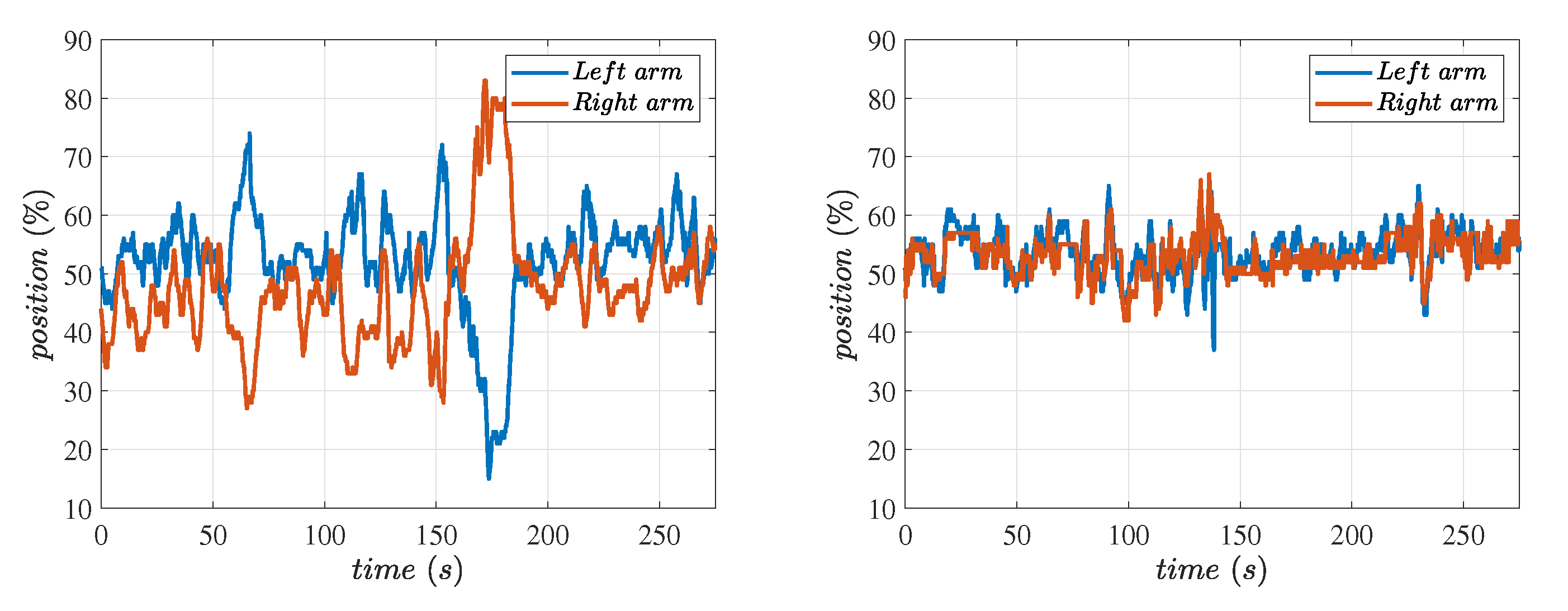
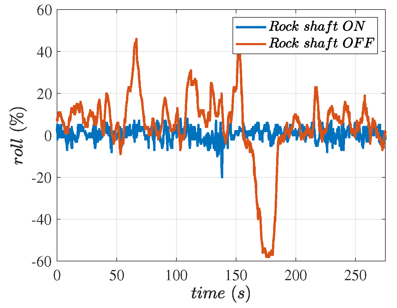
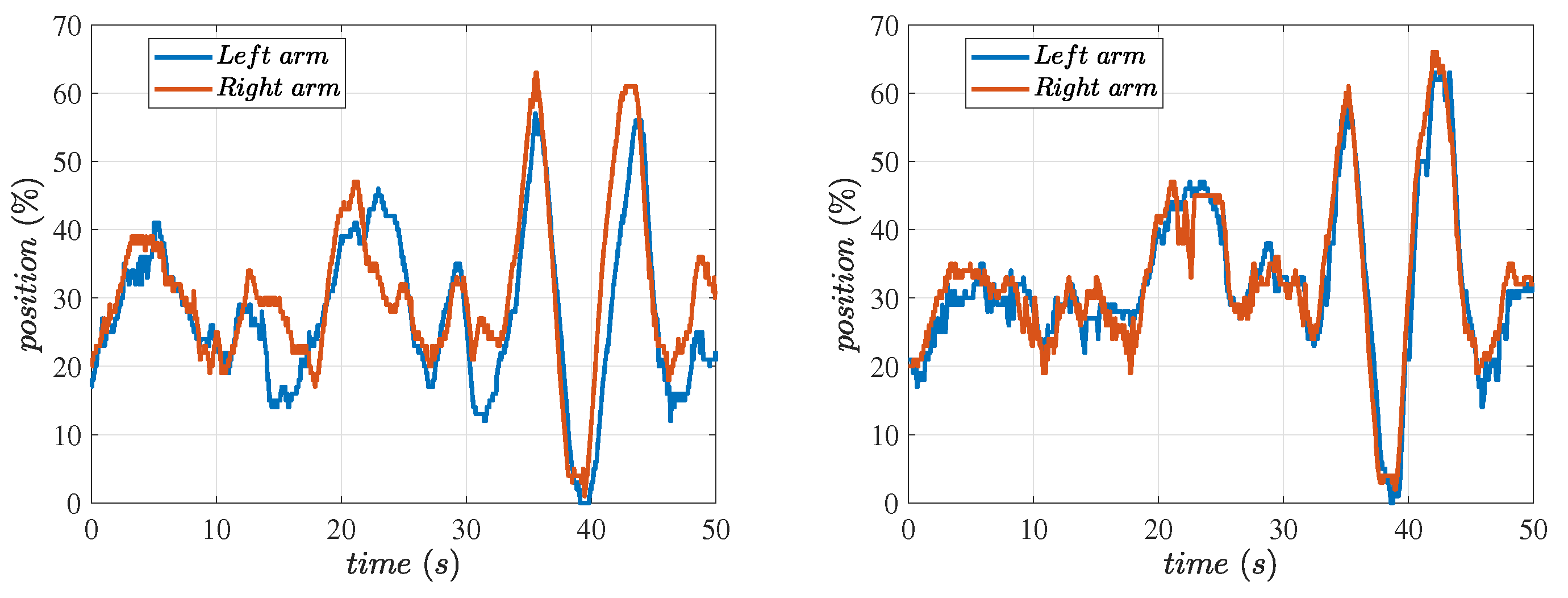
5.2. Float Control of the Hitch System Using Software Rock Shaft Algorithm

In the next set of experiments, we used two implements for validating the software rock shaft algorithm in float mode: a seed drill and a flail mower. Because the three-point arms have two independent cylinders, we can set both arms in float mode independently. This is carried out by connecting both ports of each cylinder (Figure 4) to the hydraulic tank.
We started with the seed drill connected to the three-point hitch and drove the tractor on uneven terrain with the software rock shaft deactivated and activated. Figure 13 and Figure 14 present the results from two rounds of five-minute drives with the seed drill. The left plot in Figure 13 shows the position of each arm when the software rock shaft was deactivated, whereas the right plot shows the positions of the arms when the software rock shaft was activated. Figure 13 (left) shows that the implement followed the terrain about the roll axis when the software rock shaft was deactivated. While, in the case of some implements, this can offer an advantage, it may be more desirable to achieve a zero-roll condition for the implement with respect to the tractor in most cases. In other words, it may be more important to follow the tractor about the roll axis than to follow the terrain, similar to the case of the physical rock shaft found on traditional tractors. Figure 14 compares the roll between the two cases for the same terrain when driven at approximately the same velocity. Figure 15 shows two images of the tractor with the seed drill implement. The left image shows the implement tilted to its left when the software rock shaft was deactivated. The image on the right shows the implement in a reasonably zero-roll position when the software rock shaft was activated. The images were captured at the same location and under the same terrain conditions. The adverse effect on the seed drill in float mode without correcting the roll can be seen in Figure 15 (left). The seed drill, which has a wheel at the center and no wheels on the sides, is an unstable equilibrium system. When the system was perturbed with uneven terrain, the implement became unstable about the roll axis. Once we implemented Algorithm 1, the hitch system was able to maintain the implement close to a zero-roll angle as shown in Figure 13 (right) and Figure 14; that is, the implement was able to follow the tractor rather than the terrain around the roll axis while moving up and down with the terrain along the same axis of the tractor’s motion. This effect can be seen very clearly in Figure 15 (right), showing a significant reduction in roll.
Similarly, in the next sub-experiment, we drove the tractor on uneven terrain with a flail mower connected with software rock shaft activated and deactivated, and the results for which are shown in Figure 16 and Figure 17. Figure 16 (left) and Figure 16 (right) show the positions of the arms with the software rock shaft deactivated and activated, respectively. Figure 17 compares the roll between the software rock shaft turned off and turned on test cases. Figure 16 (left) shows a larger roll when the software rock shaft was deactivated, whereas the roll was negligible with the software rock shaft activated (Figure 16, right). In Figure 17, even with the small overall roll, we saw that the software rock shaft was able to improve the roll performance of the flail mower. Due to the roller spanning the width at the back of the flail mower, it was seen that this implement performed well without the software rock shaft since no significant roll was observed (Figure 18, left). Nevertheless, there was an amount of roll that the software rock shaft could fix. This effect can be clearly seen in Figure 18, which shows two images of the tractor with the flail mower. The left image shows the implement tilted with respect to the tractor when the software rock shaft was deactivated, whereas the right image shows the implement staying flat with respect to the tractor when the software rock shaft was activated.
Table 4 summarizes the effect of the software rock shaft algorithm on the roll of an implement. It can be seen that the seed drill’s roll was significantly reduced from the mean of 4.64% to 0.58%. The standard deviation (SD) was reduced from 16.77% to 2.79%. As mentioned above, the roll percent was not significant in the case of the flail mower without the software rock shaft; however, it could still improve the mean roll percent from 3.99 % to 0.59 %, and the SD from 6.45% to 3.53%. As shown in Figure 8, the implement roll of 4.64%, 16.77%, 3.99 %, and 6.45%, observed with software rock shaft off, correspond to up to 1.93°, 6.97°, −1.66°, and 2.69°, respectively.
It should be noted that for implements like the seed drill shown in Figure 15, it is desirable to activate the software rock shaft since such implements have an unstable equilibrium due to contact with the ground with wheels in the center. In addition, implements with an off-center center of mass may also need the software rock shaft algorithm. However, for implements like a mower shown in Figure 18, which have a larger surface contact with the ground, the software rock shaft can be deactivated since in this operation following the terrain is more desirable than maintaining a zero roll with respect to the tractor.

6. Conclusions

In this paper, we introduced an innovative hitch system with the lower arms actuated by two independent hydraulic cylinders. We then devised a position controller for individual lower arms and a roll controller to move these arms together. We presented experimental results from the step response of the hitch system’s height while tracking a velocity reference. In summary, in position control mode, we achieved three goals: (a) reaching a desired position, (b) moving at the commanded velocity while moving to the position setpoint, and (c) maintaining close to zero roll while moving up or down. We observed that the largest mean roll was 0.23% with a flail mower attached and 0.26% without any implement. We then presented a novel algorithm to emulate a physical rock shaft while the implement operates in float mode. Our results with this novel software rock shaft show that the implement can follow the terrain by moving vertically while also maintaining a zero roll about the fore–aft axis. We also compared these results with the case where both cylinders were free to float without the assistance of the software rock shaft. The experiments showed a significant reduction in roll when the software rock shaft was turned on. The mean roll reduced from 4.64% to 0.58% with a seed drill implement and from −3.99% to −0.59% with a flail mower implement. The standard deviations in these two implement cases improved from 16.77% to 2.79% and 6.45% to 3.53%, respectively, showing that the software rock shaft algorithm designed in this paper can emulate and replace physical rock shafts present on traditional tractors.
We have presented a promising start with our initial results on hitch control in tractors with independent cylinders for three-point arms in both position and float modes. Looking ahead, we envision further advancements: we plan to delve deeper into understanding the variation in the cylinders and implements, such as changes in mass and shifts in the center of mass during operation. Additionally, we are committed to enhancing the software rock shaft algorithm’s performance, particularly for implements with the center of mass outside the tractor’s lateral dimension. This includes implements like an offset flail ditch bank mower [42] when extended out. Also, the scope of this study was limited to the implement position and roll control. In the future, we would like to use the current hitch architecture to actively control the pitch of an implement by actuating the hydraulic top link cylinder. Additionally, on the rock shaft front, it is a valuable feature to be able to select either a software rock shaft or no rock shaft in real time, depending on the type of ground the vehicle is operating on and the desired groundwork outcome. These future improvements hold great promise for the field of tractor technology.

7. Patents

  • Tractor Three-point Hitch Control for an Independent Lower Arms System [43]
  • Three-point hitch control system [44]
  • Three-point hitch hook up assist system [27]

Author Contributions

Conceptualization, Y.M.C. and Z.O.; methodology, Y.M.C.; software, Y.M.C.; validation, Y.M.C., S.C. and K.S.J.; formal analysis, Y.M.C., S.C., K.S.J. and N.E.; investigation, Y.M.C., S.C., K.S.J. and N.E.; resources, U.A.R. and Z.O.; data curation, Y.M.C., S.C. and K.S.J.; writing—original draft preparation, Y.M.C.; writing—review and editing, Y.M.C., N.E., U.A.R. and Z.O.; visualization, Y.M.C., S.C. and K.S.J.; supervision, Z.O.; project administration, Z.O.; funding acquisition, Z.O. All authors have read and agreed to the published version of the manuscript.

Funding

This research was supported by Zimeno, Inc. dba Monarch Tractor, Livermore, CA, USA.

Data Availability Statement

The data and plots presented in this article are from the original contributions of the study; further inquiries can be directed to the corresponding author.

Acknowledgments

The authors wish to thank Matt O’Brien for insightful discussions while preparing the manuscript. The authors also appreciate the support from Monarch Tractor and the permission from them for this research to be conducted and published.

Conflicts of Interest

All the authors are currently employees of Zimeno Inc., dba Monarch Tractor, where they conducted the research. Yogesh M Chukewad and Zachary Omohundro are co-inventors on a provisional patent application that includes all the concepts and results presented in the manuscript. The patent is– “Tractor Three-point Hitch for an Independent Lower Arms System." Provisional Application Number: 63/644,704. The details of other relevant patent applications are included in the manuscript.

References

  1. Moreda, G.; Muñoz-García, M.; Barreiro, P. High voltage electrification of tractor and agricultural machinery–A review. Energy Convers. Manag. 2016, 115, 117–131. [Google Scholar] [CrossRef]
  2. Yu, J.H.; Park, J.K.; Cheon, S.H.; Byeon, S.J.; Lee, J.W. Development of a rolling angle estimation algorithm to improve the performance of implement leveling-control systems for agricultural tractors. Adv. Mech. Eng. 2022, 14, 16878132221138310. [Google Scholar] [CrossRef]
  3. Florentsev, S.; Izosimov, D.; Makarov, L.; Baida, S.; Belousov, A. Complete traction electric equipment sets of electro-mechanical drive trains for tractors. In Proceedings of the 2010 IEEE Region 8 International Conference on Computational Technologies in Electrical and Electronics Engineering (SIBIRCON), Irkutsk, Russia, 11–15 July 2010; pp. 611–616. [Google Scholar]
  4. Ueka, Y.; Yamashita, J.; Sato, K.; Doi, Y. Study on the development of the electric tractor: Specifications and traveling and tilling performance of a prototype electric tractor. Eng. Agric. Environ. Food 2013, 6, 160–164. [Google Scholar] [CrossRef]
  5. Mocera, F.; Somà, A. Analysis of a parallel hybrid electric tractor for agricultural applications. Energies 2020, 13, 3055. [Google Scholar] [CrossRef]
  6. Mousazadeh, H.; Keyhani, A.; Javadi, A.; Mobli, H.; Abrinia, K.; Sharifi, A. Life-cycle assessment of a Solar Assist Plug-in Hybrid electric Tractor (SAPHT) in comparison with a conventional tractor. Energy Convers. Manag. 2011, 52, 1700–1710. [Google Scholar] [CrossRef]
  7. Chen, Y.C.; Chen, L.W.; Chang, M.Y. A design of an unmanned electric tractor platform. Agriculture 2022, 12, 112. [Google Scholar] [CrossRef]
  8. Monarch Tractor MK-V. Available online: https://www.monarchtractor.com/mk-v-electric-tractor (accessed on 25 April 2024).
  9. Boe, T.E.; Bergene, M.A. Tractor three-point hitch control system. SAE Trans. 1989, 98, 229–236. [Google Scholar]
  10. Kushwah, A.; Chouriya, A.; Tewari, V.; Gupta, C.; Chowdhury, M.; Shrivastava, P.; Bhagat, P. A novel embedded system for tractor implement performance mapping. Cogent Eng. 2024, 11, 2311093. [Google Scholar] [CrossRef]
  11. Bhondave, B.; Ganesan, T.; Varma, N.; Renu, R.; Sabarinath, N. Design and development of electro hydraulics hitch control for agricultural tractor. SAE Int. J. Commer. Veh. 2017, 10, 405–410. [Google Scholar] [CrossRef]
  12. Kumar, S.; Tewari, V.K.; Bharti, C.K.; Ranjan, A. Modeling, simulation and experimental validation of flow rate of electro-hydraulic hitch control valve of agricultural tractor. Flow Meas. Instrum. 2021, 82, 102070. [Google Scholar] [CrossRef]
  13. Sun, X.; Lu, Z.; Song, Y.; Cheng, Z.; Jiang, C.; Qian, J.; Lu, Y. Development status and research progress of a tractor electro-hydraulic hitch system. Agriculture 2022, 12, 1547. [Google Scholar] [CrossRef]
  14. Nataraj, E.; Sarkar, P.; Raheman, H.; Upadhyay, G. Embedded digital display and warning system of velocity ratio and wheel slip for tractor operated active tillage implements. J. Terramechanics 2021, 97, 35–43. [Google Scholar] [CrossRef]
  15. Xi, Z.; Feng, T.; Liu, Z.; Xu, H.; Zheng, J.; Xu, L. Estimation of Soil Characteristic Parameters for Electric Mountain Tractor Based on Gauss–Newton Iteration Method. World Electr. Veh. J. 2024, 15, 217. [Google Scholar] [CrossRef]
  16. Ro, Y.M.; Moon, J.H.; Kim, K.U. Performance improvement of the horizontal control system for a tractor implement using sensor signal from the front axle. J. Biosyst. Eng. 2016, 41, 67–74. [Google Scholar] [CrossRef]
  17. Cheng, Z.; Lu, Z. Research on the PID control of the ESP system of tractor based on improved AFSA and improved SA. Comput. Electron. Agric. 2018, 148, 142–147. [Google Scholar] [CrossRef]
  18. Khalaji, A.K. PID-based target tracking control of a tractor-trailer mobile robot. Proc. Inst. Mech. Eng. Part C J. Mech. Eng. Sci. 2019, 233, 4776–4787. [Google Scholar] [CrossRef]
  19. David, S.A.; de Sousa, R.V.; Valentim Jr, C.A.; Tabile, R.A.; Machado, J.A.T. Fractional PID controller in an active image stabilization system for mitigating vibration effects in agricultural tractors. Comput. Electron. Agric. 2016, 131, 1–9. [Google Scholar] [CrossRef]
  20. Wang, L.; Wang, Y.; Dai, D.; Wang, X.; Wang, S. Review of electro-hydraulic hitch system control method of automated tractors. Int. J. Agric. Biol. Eng. 2021, 14, 1–11. [Google Scholar] [CrossRef]
  21. Li, M.; Wang, L.; Liu, J.; Ye, J. Method study on fuzzy-PID adaptive control of electric-hydraulic hitch system. In Proceedings of the International Conference on Advances in Materials, Machinery, Electronics (AMME 2017), Wuhan, China, 25–26 February 2017; Volume 1820. [Google Scholar]
  22. Meena, K.; Dhavalikar, M.; Thorat, S. A review on the position control of hydraulic cylinder for accuracy and response time. Mater. Today Proc. 2023, 72, 995–999. [Google Scholar] [CrossRef]
  23. Manring, N.D.; Fales, R.C. Hydraulic Control Systems; John Wiley & Sons: Hoboken, NJ, USA, 2019. [Google Scholar]
  24. Cundiff, J.S. Fluid Power Circuits and Controls: Fundamentals and Applications; CRC Press: Boca Raton, FL, USA, 2001. [Google Scholar]
  25. Hook, R.; Murphy, K. Depth Control of Integral Flexible Implements; Technical Report, SAE Technical Paper; SAE International: Warrendale, PA, USA, 1969. [Google Scholar]
  26. Land Pride Box Scraper BB12. Available online: https://www.landpride.com/products/58/BB12-Series-Box-Scrapers (accessed on 29 April 2024).
  27. Omohundro, Z.M.; Chenjia, Y.; Jutkowitz, A.; Chukewad, Y.M. Three-Point Hitch Hook Up Assist System. US Patent App. 18/164,592, 5 February 2023. [Google Scholar]
  28. White, E. Relation of the Tractor to the Implement. SAE Trans. 1919, 14, 323–334. [Google Scholar]
  29. Johannsen, B. Tractor Hitches and Hydraulic Systems—An Implement Designer’s Viewpoint. SAE Trans. 1954, 62, 173–185. [Google Scholar]
  30. Kubota Float Function Demonstration. Available online: https://www.wickhamtractor.com/kubota-float-function (accessed on 3 June 2024).
  31. Shafaei, S.; Loghavi, M.; Kamgar, S. Development and implementation of a human machine interface-assisted digital instrumentation system for high precision measurement of tractor performance parameters. Eng. Agric. Environ. Food 2019, 12, 11–23. [Google Scholar] [CrossRef]
  32. Al-Janobi, A. A data-acquisition system to monitor performance of fully mounted implements. J. Agric. Eng. Res. 2000, 75, 167–175. [Google Scholar] [CrossRef]
  33. Yahya, A.; Zohadie, M.; Kheiralla, A.; Giew, S.; Boon, N. Mapping system for tractor-implement performance. Comput. Electron. Agric. 2009, 69, 2–11. [Google Scholar] [CrossRef]
  34. Sandeep, T.; Prashant, K.; Abhijit, H.; Swarupanand, S.; Sanjeev, H. Study on Various Position Sensing Technologies in Tractor Hitch Application: Paper No.: 2023-JL-05. ARAI J. Mobil. Technol. 2023, 3, 820–834. [Google Scholar] [CrossRef]
  35. Novotechnik Novohall Rotary Sensor. Available online: https://www.novotechnik.com/resources/data-sheets/rotary-shaft-type/59_DS_295_RSA-3200_Ratiometric–enUS.pdf (accessed on 21 April 2024).
  36. Hydac Proportional Needle Valve PWSM06020W. Available online: https://www.hydac.com/_de-es/productos/valves/proportional-valves/proportional-needle-valves-poppet-type/pwsm06020w.html?type=9999 (accessed on 7 May 2024).
  37. Hydac Electronic Pressure Transmitter HPT 146K-R-0250-077. Available online: https://www.hydac.com/shop/en/sensors/pressure-sensors/pressure-transmitters (accessed on 29 April 2024).
  38. HYDAC HY-TTC-580 Series. Available online: https://catalog.hydac.com/viewitems/controllers/hy-ttc-580 (accessed on 14 April 2024).
  39. Cunha, M.A.; Guenther, R.; De Pieri, E.R.; De Negri, V.J. Design of cascade controllers for a hydraulic actuator. Int. J. Fluid Power 2002, 3, 35–46. [Google Scholar] [CrossRef]
  40. Tierre Lupo 140. Available online: https://www.tierreonline.com/en/grass-cutter/lupo-revers/ (accessed on 26 April 2024).
  41. Schmeiser Seed Drill VD48PW. Available online: https://www.tgschmeiser.com/products/vineyarddrills/no-till.html (accessed on 26 April 2024).
  42. FHM Standard Ditch Bank Flail Mower AGL125. Available online: https://www.farmer-helper.com/proDetail.aspx?id=2999 (accessed on 29 April 2024).
  43. Omohundro, Z.M.; Chukewad, Y.M.; Jutkowitz, A. Tractor Three-Point Hitch Control for an Independent Lower Arms System. US Provisional Patent App. 63/644,704, 9 May 2024. [Google Scholar]
  44. Omohundro, Z.M.; Jutkowitz, A.; Chukewad, Y.M. Three-point hitch control system. US Provisional Patent App. 18/522,088, 28 November 2023. [Google Scholar]
Figure 1. Three-point hitch system of the Monarch Tractor’s MK-V platform, shown in the side-view (left) and the rear-view (right). The major components are one hydraulic top link cylinder and two independently controlled hydraulic cylinders for the lower arms. The coordinate axes are shown for reference. The roll is defined as the rotation of the implement, attached to the lower arms, around the X-axis.
Agriengineering 06 00100 g001
Figure 2. Schematic of the side-view of one of the hitch arms highlighting the involved geometry. The hitch arms are pivoted at point O, which lies on the tractor chassis. The hydraulic cylinder is attached to the tractor chassis and the hitch arm at pivot points A and B, respectively. δ denotes the angle between the tractor chassis O A and the vertical. C is the lift point of the hitch arms, and it is also a spherical joint.
Agriengineering 06 00100 g002
Figure 3. Plots demonstrating the variation in the lift point height ( z l p ) with respect to angle θ and cylinder length ( l ) . Left plot: Variation in the lift point height ( z l p ) with respect to θ in degrees (upper X-axis) and in percentage (lower X-axis). Right plot: Variation in the lift point height ( z l p ) as the hydraulic cylinder is extended, i.e., l is increased from its minimum to maximum value.
Agriengineering 06 00100 g003
Figure 4. The plant, in this case, is a set of two double-acting cylinders. One such cylinder is shown here. The top side of the cylinders is attached to the tractor chassis, and the bottom side is attached to the lower arms of the hitch system. The extend pressure tank valve and retract pressure tank valve are digital valves that are normally connected to the tank and can be controlled to connect the pressure side or the tank side to either cylinder port, while the extend enable valve and retract enable valve are normally closed proportional valves that can be controlled to allow varying amounts of flow to either port of the cylinder. In addition, mechanical relief valves are connected to both ports of the cylinder as an additional safety.
Agriengineering 06 00100 g004
Figure 5. The controller is designed to control the position and velocities of the lower arms. Two of these controllers operate in parallel on the two hydraulic lower arm cylinders. The outer loop controller runs on the position error, whereas the inner loop controller runs on the velocity error.
Agriengineering 06 00100 g005
Figure 6. The hitch control system includes a roll controller preceding individual position controllers of the two lower arms. The roll controller adjusts the set points for individual position controllers according to the roll in the implement, which is defined as the difference between the left arm position and the right arm position. In an ideal case of no roll in the implement, the individual controllers would work according to the system’s set point for the hitch height. However, for example, if there is a positive roll when the hitch is commanded to go up (the left arm is higher than the right), the left would slow down, and the right one would speed up. Similarly, the controller also takes care of situations when there is a case of a negative roll or the hitch is commanded to go down with positive or negative rolls.
Agriengineering 06 00100 g006
Figure 7. Top: Geometry of a connected implement (blue) with off-center center of mass while the tractor (green) moves on uneven terrain (black). The tractor has a roll angle of β with respect to the horizontal, and the implement has a roll angle of α with respect to the tractor’s plane. The implement has an offset center of mass, which is distance d away from the center, and it has two wheels attached at a distance of w from the center. The height of the wheels’ contact from the ground to the implement’s plane is p. Bottom: free body diagram of the implement of mass m. The distance between the implement’s mount points is L, which varies with α . The left and right three-point arms apply hydraulic forces whose components YZ plane are F L , y z and F R , y z , respectively, and they are perpendicular to the tractor’s roll plane. The reaction forces at the mount points are resolved into components along ( R L , a , R R , a ) and perpendicular ( R L , p , R R , p ) to the implement’s plane. The implement experiences normal reactions N L , N R and frictional forces F L , f r i c , F R , f r i c from the contact of its left and right wheels, respectively, with the ground.
Agriengineering 06 00100 g007
Figure 8. Roll of hitch arms in degrees compared to roll in % for two different hitch configurations. The narrow configuration corresponds to a distance of 86 cm between hitch arms, while the wide configuration corresponds to a distance of 123 cm between hitch arms. These configurations are usually adjusted manually using the stabilizers on the side of the lower arms.
Agriengineering 06 00100 g008
Figure 9. Results from 17 trials conducted on a tractor while moving the hitch up in position control without an implement attached. Left plot: Position of the hitch. The hitch was initially at 20% and a set point of 80% was commanded. Center plot: Velocity of the hitch. A velocity set point of 25%/s was commanded. Right plot: Roll of the hitch system. The roll controller aims to maintain zero roll of the hitch.
Agriengineering 06 00100 g009
Figure 10. Results from 17 trials conducted on a tractor while moving the hitch down in position control without an implement attached. Left plot: Position of the hitch. The hitch was initially at 80% and a set point of 20% was commanded. Center plot: Velocity of the hitch. A velocity set point of −25%/s was commanded. Right plot: Roll of the hitch system. The roll controller aims to maintain zero roll of the hitch.
Agriengineering 06 00100 g010
Figure 11. Results from 21 trials conducted on a tractor while moving the hitch up in position control with a flail mower attached. Left plot: Position of the hitch. The hitch was initially at 50% and a set point of 100% was commanded. Center plot: Velocity of the hitch. A velocity set point of 25%/s was commanded. Right plot: Roll of the hitch system. The roll controller aims to maintain zero roll of the hitch.
Agriengineering 06 00100 g011
Figure 12. Results from 21 trials conducted on a tractor while moving the hitch down in position control with a flail mower attached. Left plot: Position of the hitch. The hitch was initially at 100% and a set point of 50% was commanded. Center plot: Velocity of the hitch. A velocity set point of −33%/s was commanded. The overshoot in the velocity can be due to the sudden drop of the implement due to its weight. Right plot: Roll of the hitch system. The roll controller aims to maintain zero roll of the hitch.
Agriengineering 06 00100 g012
Figure 13. Positions of the left and right arms in % with software rock shaft off (left) and with software rock shaft turned on (right) while using a Schmeiser seed drill.
Agriengineering 06 00100 g013
Figure 14. Comparison of the roll (difference between the left and right hitch arms in %) while using a Schmeiser seed drill. It was observed that there was a large roll when the software rock shaft was turned off.
Agriengineering 06 00100 g014
Figure 15. A 4-foot Schmeiser seed drill attached to the tractor, driven around on rough terrain in float mode. Left image: The software rock shaft was turned off. It was observed that the implement followed the terrain but did not stay flat since each cylinder was in float mode. Right image: The software rock shaft was turned on. It was observed that the implement followed the terrain and stayed flat as well.
Agriengineering 06 00100 g015
Figure 16. Positions of the left and right arms in % with software rock shaft off (left) and with software rock shaft turned on (right) while using a Tierre Lupo flail mower.
Agriengineering 06 00100 g016
Figure 17. Comparison of the roll (difference between the left and right hitch arms in %) while using a Tierre Lupo flail mower. It was observed that there was noticeable roll when the software rock shaft was turned off.
Agriengineering 06 00100 g017
Figure 18. A flail mower attached to the tractor, driven around on rough terrain in float mode. Left image: The software rock shaft was turned off. Despite the subtle difference, it was observed that the implement followed the terrain around the roll axis. Right image: The software rock shaft was turned on. It was observed that the implement followed the tractor around the roll axis.
Agriengineering 06 00100 g018
Table 1. List of hitch geometry parameters shown in Figure 2, which define the geometry of the actuator.
ParameterValue
a75.0 cm
b30.0 cm
c70.0 cm
z o 25.3 cm
l53.3 cm to 79.0 cm
θ 35.0 ° to 86.4 °
δ 8.0 °
Table 2. List of test parameters, including initial positions and set points, with velocity references for the position control experiments. A total of 76 trials were carried out in both directions with and without implement.
DirectionImplement
(Flail Mower)
Initial Position
(%)
Set Point
(%)
Target Speed
(%/s)
Trials
UpNo20802517
DownNo8020−2517
UpYes501002521
DownYes10050−3321
Table 3. The mean and standard deviation (SD) values for the roll with active supervisory roll controller devised in our hitch position controller.
ImplementWeight (kg)Motion DirectionMean (%)SD (%)
No implementN/AUp0.260.23
No implementN/ADown 0.16 1.24
Tierre Lupo Flail Mower240Up 0.20 0.66
Tierre Lupo Flail Mower240Down 0.23 0.45
Table 4. The mean and standard deviation (SD) values for roll of two different implements with rock shaft off and on.
ImplementWeight (kg)Software Rock ShaftMean (%)SD (%)
Schmeiser Seed Drill515Off4.6416.77
Schmeiser Seed Drill515On0.582.79
Tierre Lupo Flail Mower240Off 3.99 6.45
Tierre Lupo Flail Mower240On 0.59 3.53
Disclaimer/Publisher’s Note: The statements, opinions and data contained in all publications are solely those of the individual author(s) and contributor(s) and not of MDPI and/or the editor(s). MDPI and/or the editor(s) disclaim responsibility for any injury to people or property resulting from any ideas, methods, instructions or products referred to in the content.

