Abstract
The article presents factors influencing the germination and development of plants after seeding with disk seeders. Schemes of improved two-disk seeders are proposed, forces acting on the improved seeder during operation, determination of the maximum distance between the seeder disks at the field surface level, and calculation schemes for determining the draft resistance of the serial and improved seeders, the area of the flat disk segment of the seeder, determination of the deformer, and tailstock area of the pressing plate. During the theoretical study of the seeding process, the following parameters and observations were obtained: analytical dependencies of soil density created by the pressing plate; geometric parameters of the pressing plate with a curvature radius r = 52…57 mm, plate section thickness of 2.5 mm; installation of the pressing plate insignificantly increases the draft resistance of the seeder; and the depth of the seeder’s travel has the greatest influence on spring deformation. Experimental studies reveal that the stiffness of the pressing plate is 7500…7600 N/m, ensuring an optimal furrow bottom density of 1.1–1.3 g/cm3; in the range of seed embedding depth of 0.05…0.07 m, 89% of the total number of seeds are placed compared to 76% of seeds embedded by the serial seeder.
1. Introduction
Increasing grain production is of great importance for agriculture today. To boost grain production, it is necessary to increase the yield of cereal crops while maintaining sowing areas. The yield of cereal crops depends not only on the introduction of new high-yielding varieties that match intensive technologies but also significantly on the quality of seeding [1,2]. The quality of seeding implies creating optimal conditions in the soil environment that have a favorable impact on the germination of seeds of cereal crops, achieved by the covering working organs. These conditions include the depth of seed covering, the condition of the furrow bottom, the state of the upper soil layer in the furrow after seed covering, uniformity of seed covering in depth, and the tight contact of seeds with the solid phase of the soil, i.e., the bottom of the furrow [3,4,5]. One of the important factors for seed germination is the depth of planting and the tight contact of seeds with the bottom of the furrow, which significantly influences the intensity of seed germination, the uniformity of seedlings, enhances the energy of plant growth, and ultimately increases the yield of cereal crops [6,7]. Any impact on the soil, including during planting, alters the density of the seeding layer of soil, which affects the entire complex of physical conditions: water, air, and thermal regimes, and, consequently, the conditions of biological activity [8,9,10].
Moisture is required for seeds to germinate. The soil must contain sufficient moisture to allow seed germination to occur. In the arid zone of western Kazakhstan, the soil is usually not sufficiently moistened during the sowing period; therefore, to maintain the moisture content in the soil, an agrotechnical technique such as rolling the crops is used [11]. As a result of rolling, the loose soil is compacted, its capillarity is restored, moisture from the lower layers rises, and the humidity in the seed placement area increases. However, when rolling, an important condition must be taken into account, which is the fact that the soil surface must remain loose, otherwise, as indicated, water from the lower horizons will quickly rise up through the capillaries and evaporate. For example, the yield of spring wheat increases as the density of the soil above the seeds increases to 0.95…1.00 g/cm3, and an increase in density of more than 1 g/cm3 leads to a decrease in yield [12,13]. When cultivating the soil, the main condition for ensuring good germination and further development of plants is loosening the top layer of soil to the depth of planting the seeds and forming a dense seed bed, i.e., the layer in which the seeds are located. Compacting the bottom of the furrow causes the flow of moisture and nutrients to the seeds and, therefore, increases their germination. The loose top layer above the seeds in the groove does not allow moisture to evaporate, and at the same time provides air flow to the seeds, which has a beneficial effect on their germination [14].
When sowing, compliance with agrotechnical deadlines is important. It is during this short period of time that the soil acquires such physical and mechanical characteristics that favor its cultivation at minimal cost. The granulometric composition, humidity, density, stickiness and other characteristics of the soil during the sowing period take on optimal values, from the point of view of soil cultivation. Any impact on the soil, including during sowing, changes the density of the seed layer of soil, which affects the entire complex of physical conditions: water, air, and thermal regimes and, consequently, the conditions of biological activity [15]. The above analysis of the influence of the quality of seed placement on the yield of agricultural crops allows us to formulate the basic requirements for the seeding working parts of seeders. They must provide a compacted seed bed of optimal density; cover the seeds on top with loose soil; and ensure uniformity of seed placement depth. The high-quality work of the seeder is largely determined by one of its structural elements that interacts with the soil: the coulter.
The quality of work of the coulters of grain seeders is a set of properties that characterize the success of the technological process. Based on the available types of opener designs, many different seeding working bodies and seeding technologies have been developed and studied [16,17,18,19,20,21]. These combined covering working elements have rolling rollers that press seeds into the bottom of the furrow formed by some type of coulter [22]. As a result, the seeds are placed in a dense bed and covered from above with loose soil. However, such coulters are characterized by complex construction and high material consumption. The furrow-forming elements used in them have the same disadvantages as standard coulters, and the seed-pressing rollers, when working in wet soil, stick to it and bring the seeds to the surface. To prevent this from happening, it is necessary to eliminate the contact of the working parts of the coulter with the seeds and, at the same time, ensure compaction of the furrow bottom. Among the various coulters used in the designs of grain seeders, the most common type is the two-disc coulter. It is used in domestic seeders such as the SZ-5.4, SZ-3.6, and their modifications, as well as in foreign ones such as the 5100 (Case IH Company, Racine, WI, USA), 8000 (Deere & Company Company, Molin, IL, USA), End Wheel (Great Plains Manufacturing, Salina, KS, USA), and others. However, the disc coulters of these seeders do not fully meet agronomic requirements, as they do not create compaction of the bottom of the seeding furrow, and, therefore, do not provide the necessary moisture regime for the sown seeds. Additionally, they unevenly distribute seeds in terms of depth. This leads to delayed seed germination, worsens the conditions for further plant development, and reduces yields. As a result, there is a need to improve the design of the two-disc coulter for quality seed covering. The technical solution to this is the installation of a detachable pressing plate, which ensures uniform distribution of seeds in depth by crushing soil clods and pressing seeds to the bottom of the furrow, creating the necessary density for the seed bed and ensuring contact between seeds and the bottom of the furrow. To achieve the set goal, it is necessary to solve the following tasks:
- Based on the analysis of literary sources and patent databases, determine the promising direction for improving the disk seeders of grain seeders and justify the design and technological scheme of the planting working element;
- Conduct theoretical studies of the technological process of seed planting with uniform distribution of seeds by depth and justify the parameters of the pressing plate;
- Experimentally study in laboratory and field conditions the influence of design parameters of the pressing plate on the uniformity of seed placement by planting depth.
2. Materials and Methods
2.1. The Scheme of an Improved Disc Coulter
To implement the proposed technology, we have developed a covering working element—an improved coulter (Figure 1) [21]. The details of the coulter are maximally standardized with the coulter of a grain seeder of the SZ-3.6 type. The improved opener consists of a housing (1), two flat disks (2) mounted on ball bearings placed in the housings (3), a driver bracket (4), a seed guide (5), and a pressure plate (6). The pressure plate is made concave in the form of a beam of equal resistance and the upper part (7) is installed parallel to the seed guide with an inclination forward. The concavity gradually turns into a curved section (radius) (8) of the pressure plate. Direct inclined section-deformer (9) of the pressure plate is made with an angle of inclination to the horizontal surface of the bottom of the furrow, less than the angle of friction of the soil on the material of the inclined section (9) and then passes into the horizontal shank (10). The pressure plate is installed between the disks with a gap and the possibility of elastic deformation under the influence of the resistance force of soil lumps to destruction. The part (11) of the pressure plate protruding beyond the inter-disk space is located no higher than the level of the soil surface and forms with the disks a space that is maximally closed on three sides. To attach the coulter to the seeder frame, a driver bracket is provided. In the upper part of the pressure plate there are longitudinal holes (12) for fastening bolts (13), which allow you to adjust the height of the pressure plate and the amount of force acting on the seeds and the soil mass around the seeds at the bottom of the furrow. The upper part of the plate is equipped with a flat platform (14). Between the pressure plate and the housing there is a scraper (15), pressed to the body with the help of bolts.
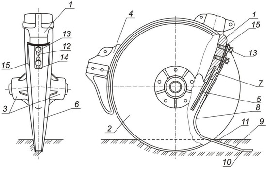
Figure 1.
Improved opener: 1. housing; 2. two flat disks; 3. ball bearings placed in the housings; 4. driver bracket; 5. seed guide; 6. pressure plate; 7. pressure plate upper part; 8. pressure plate curved section; 9. pressure plate direct inclined section; 10. pressure plate horizontal shank; 11. pressure plate protruding beyond the inter-disk space part; 12. longitudinal holes; 13. bolts; 14. flat platform; 15. scraper.
The coulter works as follows. The discs, rotating in bearings, cut into the soil and enter it. As the coulter moves inside the groove formed by the discs, the pressure plate also moves. Seeds falling to the bottom of the furrow fall under the pressure plate, which presses them to the bottom with a deformer and presses them into the seed bed with a shank. The pressure plate slides along the bottom of the furrow, pressing the seeds to the bottom and eliminating the loading of the soil in front of it, since it has an inclination relative to the bottom of the furrow ψ < φ and is made without stepped connections and joints. The harrows following the coulter cover the seeds with loose soil from above.
A pressure plate with a concave upper part installed with an inclination forward has greater rigidity and creates a greater force for pressing the seeds to the bottom of the furrow, since the upper part is made with a box-shaped cross section and has a greater moment of resistance to bending. The scraper is designed to remove soil stuck to the discs. The force of pressing the seeds to the seed bed is regulated by moving plate 6 relative to the fastening bolts along the longitudinal holes. Thus, the pressure plate aligns the location of the seeds according to the planting depth and compacts the soil environment around the seeds, creating good contact between the seeds and the soil, which has high capillarity. This helps supply the seeds with the necessary soil moisture, and, as a result, provides conditions for their intensive germination, productive development of plants, and increased yields of grain crops.
The pressure plate can be thought of as a deformer that interacts with the soil. As a sliding-type compactor moving together with the coulter, it has a wedge-shaped shape in the vertical plane, and a curved shape in the longitudinal–vertical plane with parameters that exclude loading of the soil in front of it, i.e., the angle between the tangent to the compactor and the horizontal ψ must satisfy the condition [11]:
where φ0—the angle of friction between the soil and the surface of the compactor, degrees.
As a result of the interaction of soil particles and the bottom of the furrow with the shank of the pressure plate, these particles are simultaneously compacted and its surface layers are smoothed.
2.2. Theoretical Research to Determine the Geometric Parameters of the Pressure Plate
The pressure plate is installed in the inter-disk space with the possibility of elastic deformation under the influence of the resistance force of soil lumps and contributes to their destruction, and also does not interfere with the rotation of the disks (Figure 2). The width bп of the working part of the plate, which is in contact with the soil and deforms it, is determined in accordance with the design parameters of the opener: the radius R (or diameter D) of the disk, the angle between the disks γ and the angle α, which determines the location of the vanishing point В of the disks. The pressure plate is made of spring steel 65G according to the technical specifications of GOST 14959-79, which is characterized by increased wear resistance and relatively low cost.
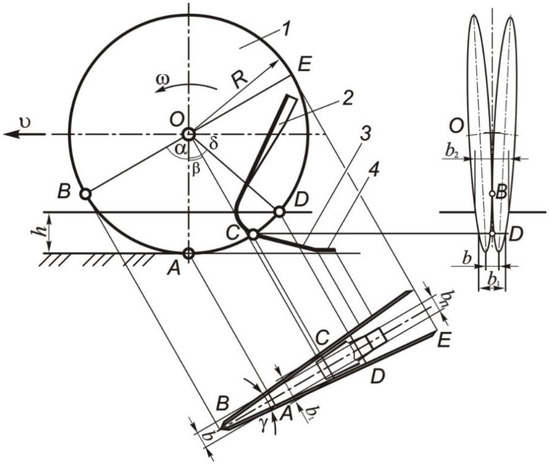
Figure 2.
Diagram of a disk coulter with a pressure plate: 1. disks; 2. pressure plate; 3. deformer; 4. shank.
In order for the pressure plate to slide along the bottom of the furrow, eliminating the loading of the soil in front of it, and to press the seeds into the soil with a horizontal shank, ensuring uniform distribution of seeds in depth and a compacted environment around them, the angle of inclination of the deformer ψ relative to the bottom of the furrow must be less than the angle of friction φ of the soil on the material pressure plate, i.e., ψ < φ, and its geometric shape is determined by its location on the opener. The width of the pressure plate elements depends on the location of its attachment and the width of the groove formed by the coulter during operation. In the serial coulter, a scraper is installed at the place where the pressure plate is attached to prevent soil from sticking. The width of the upper part of the pressure plate-handle is bр.
The width of the furrow b, m, formed by a double-disc coulter with a disc angle γ, in its lower part-point A (see Figure 2) is equal to [11,23,24,25,26,27]:
where R—the radius of the coulter disk, m; according to the manufacturer’s data R = 0.175 m; α—angle that determines the location of the disc vanishing point B, degrees; for coulters of the SZ-3.6 seeder, intended for row sowing α = 50°.
Taking into account the total gaps Δb between the body and the disks [11]:
where Δb is the gap between the inner side of the flat disks and the pressure plate, not shown in Figure 2.
The size bп determines the width of shank 4 of the pressure plate (see Figure 2), and the distance between the disks b1 at the level where the pressure plate extends beyond the dimensions of the disks-at point C [11]:
where βнд is the angle that determines the location of the starting point of the inclined part of the plate—the deformer, degrees.
The greatest distance between disks b2 at the level of the field surface at stroke depth a is equal to:
where
To create a compacted bed for seeds at a sowing depth h with the density of the soil skeleton at the bottom of the furrow ρ, a pressure p and an angle of external friction between steel and soil φ ≥ ψ are required. The length l of the straight inclined section of the pressure plate—the deformer—depends on the values of the angles β and ψ and the thickness of the soil layer h’, m, crushed by the inclined part of the plate [11]:
The geometric parameters of the pressure plate were determined from the strength conditions according to the performed force analysis. The pressure plate is a cantilever-mounted curved beam loaded with forces: Fн—resistance of the layer of loosened soil to deformation by the inclined element of the pressure plate (Figure 3a), Fтн—friction of the inclined part against the deformed layer, Fх—resistance to indentation of seeds and soil mass around the seeds on the bottom of the furrow with a horizontal shank, and Fтх—friction of the shank with the soil.
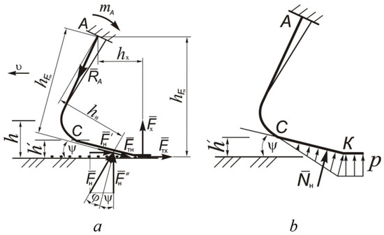
Figure 3.
Forces acting on the pressure plate: (a) general diagram of forces; (b) soil pressure on the plate.
At point A of fastening the pressure plate, reaction RA and reactive torque mA are applied. The forces acting on the plate in the dangerous section of the beam cause compressive stresses σс and bending stresses σi. The compressive stress in the dangerous section of the plate is relatively small compared to the bending stress. In this regard, the bending stress from the action of the total bending moment of external forces acting on the elements of the plate was chosen to determine it. Assuming that the resistance to crushing soil lumps by the inclined part of the plate is proportional to the amount of deformation, then the diagram of normal soil pressures on the plate deformer will have the shape of a triangle (Figure 3b). The maximum value of soil pressure p at point K of the transition of the inclined part to the shank:
The cross-section of the pressure plate in the upper concave part—the attachment point—has the form of a circular sector of the ring with radii: r—circumscribed circle (Figure 4), r1—inscribed circle, central angle αц, and coordinates x and y of the center of gravity O.
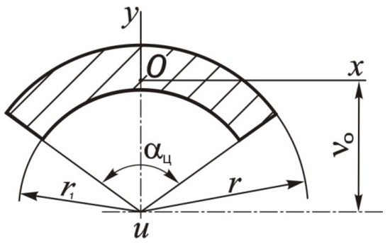
Figure 4.
Calculation diagram for determining the moment of inertia of the cross-section of the pressure plate: ν0—distance from the center of the circumscribed and inscribed circles to the center of gravity; u—center of circumscribed and inscribed circles.
Distance ν0 from the center of the circumscribed and inscribed circles to the center of gravity, mm:
Moment of inertia relative to the center of the circles, mm4 [28,29,30,31]:
Moment of inertia relative to the x axis, mm4:
where A is the cross-sectional area, mm2.
Moment of resistance relative to the x axis, mm3:
The required moment of resistance Wx is determined by the values of the bending moment Mи and the permissible bending stress [σи]:
The presented expressions and dependencies make it possible to determine the geometric parameters of the pressure plate installed in the inter-disk space of the most common coulters of grain seeders.
2.3. Theoretical Research to Determine the Spring Deformation of an Improved Opener
During the operation of the SZ-3.6 grain seeder, the depth of travel of the coulter depends on the force created by the spring installed on the bar. In this case, the coulter is in balance under the influence of external forces. In connection with changes in the design of the coulter, it is necessary to determine the dependence of the deformation of the driver spring. The coulter experiences the following forces during operation (Figure 5): —the force of gravity on the coulter assembly with the tow bar; —the resistance force against the disc movement; —the normal reaction force from the furrow bottom; -the soil friction force on the deformer surface; —the normal reaction force from the soil on the deformer; —the soil friction force on the shank surface; —the normal reaction force from the soil on the shank; and —the force exerted by the tow bar spring.
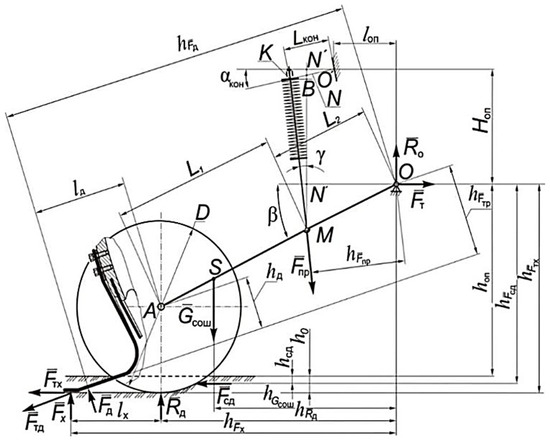
Figure 5.
Diagram of forces acting on the improved coulter during operation.
The gravity force of the opener can be determined from the expression [23,24,25,26,27]:
where is the mass of the coulter assembly, kg: coulter with a long driver weighs 13.3 kg, coulter with a short driver weighs 12.2 kg.
The force of resistance to the movement of the disk can be determined from the formula of academician V. P. Goryachkin [3,4]:
where bп—the maximum distance between the coulter disks at the level of the field surface, m; ε—speed coefficient, kPa s2/m2; ε = 1.5…2.0 kPa s2/m2.
The maximum distance between the coulter disks at the level of the field surface bп shown in Figure 6 is determined by the formula:
where ψд—angle between the planes of the disks, degrees; for the SZ-3.6 seeder ψd = 10 [4,23,24,25,26,27,28,29,30,31];
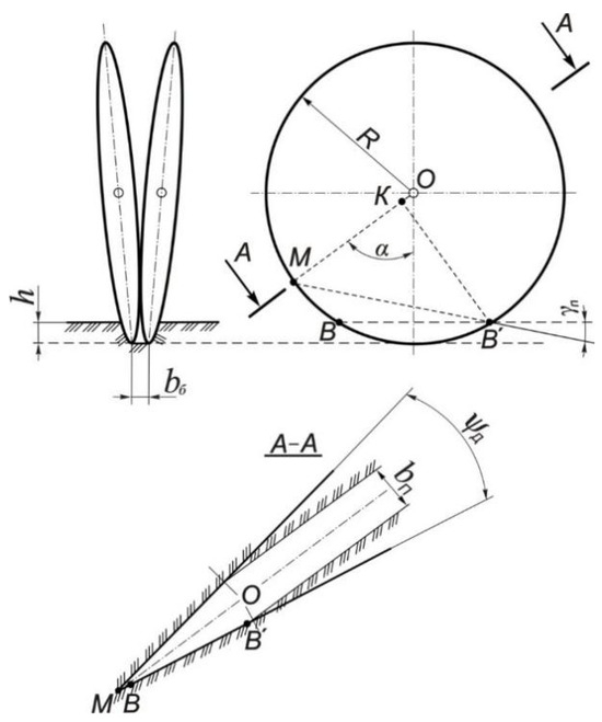
Figure 6.
Scheme for determining the maximum distance between the coulter discs at the level of the field surface.
γп—angle, degrees, determined from the expression:
Normal reaction from the bottom of the furrow to the opener, according to Letoshnev M.N. [5], is defined as the sum of two components:
where Rц—the component of the normal reaction on the cylindrical part of the disks, N; Rк—component of the normal reaction on the conical part of the disks, N;
The forces of soil friction on the deformer (), soil friction on the shank (), and normal soil reactions on the deformer () and on the shank () are constant, independent of the seeding depth and the speed of movement of the sowing unit, and are determined by calculating the traction resistance of the serial and improved openers (Rс), which consists of the following forces resistance: cutting of the disk (Rр), crushing by the chamfer (Rф), soil deformation by the side surface of the disk (Fдб), friction of the chamfer on the soil (Fтф), friction of the side surface of the disk on the soil (Fтб), normal reaction of the soil to the deformer of the pressure plate (FNд), friction of the deformer of the pressure plate on the soil (Fтд), normal reaction of the soil to the shank (resistance force to indentation of seeds and soil mass by the shank of the pressure plate) (FNх), and friction force of the shank of the pressure plate on the soil (Fтх) (Figure 7) [6,23,24,25,26,27,28,29,30,31].
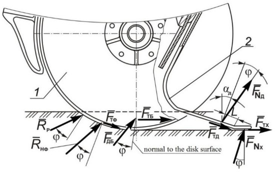
Figure 7.
Calculation diagram for determining the traction force of a serial and improved opener: 1—flat disks; 2—pressure plate; L—distance to the point of application of force Fтд.
The traction resistance of the improved opener is determined by the dependence:
Let us consider the components of the dependence of Equation (8). Resistance force to cutting by the cutting edge of the disk Rр, N [7,8,9]:
where Кр—specific cutting resistance, N/m2, for the prevailing land area Кр = 60–80 kN/m2; δ’—thickness of the coulter disk, m. δ’ = 0.0025 m.
Resistance to crushing by the chamfer of the sharpened part of the disk Rф, N:
where Fтф—the friction force of the sharpened part of the chamfer, N; θ—sharpening angle of the disk blade, degrees, θ = 18°; f—coefficient of soil friction on steel, f = 0.35…0.70 [6].
Friction force of the chamfer on the soil Fтф, N [10,11]
Soil resistance force to deformation by the lateral surface of the disk Fдб, N:
where Sсег is the area of the disk segment at the level of the field surface at the stroke depth h, m2 (Figure 8); kп—soil resistivity coefficient, N/m2; kп = 2∙104 N/m2.
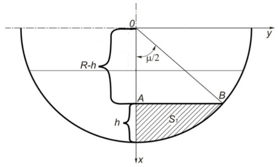
Figure 8.
Calculation diagram for determining the area opener flat disc segment.
Disc segment area, m2:
where μ—the central angle of the sector formed by the disk at the field surface level at the stroke depth h, degrees; R—segment corner radius equal to the radius of the opener disk, m.
Next, we make a variable change. From right triangle OAB:
where μ—the central angle of the segment, degrees.
Then
If x = R, then
If x = R–h, then .
Next, we substitute the obtained values into Equation (27) and after carrying out mathematical transformations we obtain:
Friction force of the lateral surface of the disk on the soil Fтдб, N:
Resistance force of the pressure plate deformer Fд, N:
where Sд—area of the pressure plate deformer, m2 (Figure 9); р—pressure creating the required soil density and acting on the pressure plate deformer, N/m2.
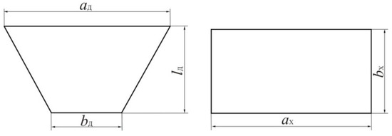
Figure 9.
Calculation diagram for determining the area: (a) deformer; (b) shank.
Deformer area Sд, m2:
where ад—the width of the upper base of the pressure plate deformer, crushing the soil mass, m; bд—width of the lower base of the pressure plate deformer, m; lд—length of the deformer, m.
Friction force of the pressure plate deformer on the soil Fтд, N:
Resistance force against indentation of seeds and soil mass by the shank of the pressure plate FNх, N:
where Sх is the area of the pressure plate shank, m2 (Figure 6b); р—pressure creating the required soil density and acting on the shank of the pressure plate, N/m2.
Shank area Sх, m2:
where ах is the length of the pressure plate shank, m; bх—width of the pressure plate shank, m.
Friction force of the pressure plate shank on the soil Fтх, N:
The force created by the spring , in this case, is a balancing force that ensures uniform movement of the coulter in the soil. To determine it, next we drew up an equilibrium equation for this system relative to the hinged fastening—point O:
where —the arm of the spring compression force, m; —opener gravity arm, m; —arm of the normal reaction of the groove bottom, m; —arm of normal soil reaction to the shank, m; —arm of the normal reaction of the soil to the deformer, m; —arm of the resistance force to the movement of the disk, m; —arm of the soil friction force on the surface of the deformer, m; and —arm of the soil friction force on the surface of the shank, m.
Spring compression force arm:
where L2 is the size (see Figure 8) determined structurally, m; for a long leash L2 = 0.33 m; for a short leash L2 = 0.20 m; β—angle of inclination of the driver in operation, degrees; γш—angle of inclination of the spring rod in operation, degrees;
where hoп is the distance from the axis of attachment of the coulter driver to the supporting surface along which the seeder moves during operation, m; this size is a constant value, for the SZ-3.6 seeder hop hoп = 0.48 m; D—opener disk diameter, m; for the SZ-3.6 seeder D = 0.35 m; L1—size (see Figure 4), determined structurally, m; for a long leash L1 = 0.520 m; for a short leash L1 = 0.325 m.
where Lкoн is the length of the console of the coulter lifting mechanism, m; for the SZ-3.6 seeder Lкoн = 0.165 m; αкoн—angle of inclination of the console in the position when the blades of the opener disks are located on the surface of movement of the support wheels of the seeder (h = 0), deg; for the SZ-3.6 seeder αкoн = 27°; Loп, Нoп—respectively horizontal and vertical coordinates of the location of the console rotation axis (see Figure 5), determined structurally, m; Loп = 0.210 m; Нoп = 0.400 m.
Opener gravity arm:
where lцт is the coordinate of the center of gravity of the opener, m.
Normal reaction arm of the sulcus bottom:
Shoulder of normal soil reaction to the shank:
where lх is the coordinate of the point of application of the soil reaction to the shank, m.
The shoulder of the normal reaction of the soil to the deformer is determined by the formula:
where lд is the coordinate of the point of application of the normal reaction of the soil to the deformer, m; ψ—angle of inclination of the deformer surface, degrees; according to condition, ψ = 22.
Shoulder of the force of resistance to the movement of the disk:
where hсд is the distance from the field surface to the resistance force to the movement of the disks, m; equal to half the sowing depth:
Shoulder of the soil friction force on the surface of the deformer:
where hд is the distance from the axis of rotation of the coulter disks to the surface plane of the plate deformer, m.
Shoulder of application of the soil friction force on the surface of the shank:
Substituting expressions (38), (41)–(45), (47), and (48) into the equilibrium Equation (37) taking into account (39), (40), and (46) we obtain:
In this case, the compression force of the spring will be determined as:
The spring deformation λ, m, can be determined by the formula:
where C is the spring stiffness of the coulter driver, N/m.
Taking into account (38), we obtain an expression for determining the spring deformation depending on the operating conditions of the seeder:
2.4. Laboratory Investigation of the Pressure Plate Elastic Property
The coulters of disc seeders are adjusted using a single depth regulator and changing the compression value of the springs on the pressure rods. The pressure force of the plate is determined by its rigidity. The elastic properties of the pressure plate were measured on a laboratory installation SM-76 to determine the deformation of the cantilever beam during plane bending.
The pressure plate (4) was secured to rigid rods (1, 2) using bolts (3) (Figure 10a). The rods were installed motionless on horizontal beam (5) of the laboratory stand. A thread (6), attached to the middle of the clamping element of the plate (4), was passed into the slot of the beam. A bowl (7) with a set of weights (8) was tied to the thread (6). Changes in the deflection of the clamping plate were recorded with a dial indicator (9) attached to the bracket. The plate deflection was measured using weights weighing 1, 2, and 5 kg placed on the bowl (Figure 10b).
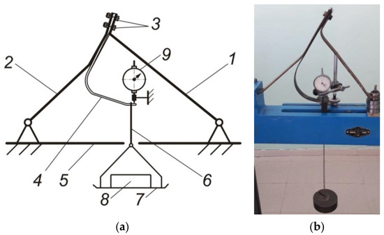
Figure 10.
To determine the rigidity of the clamping plates: (a) diagram of the experimental setup; (b) measuring deflection.
To determine the stiffness of a cylindrical spring installed on the leash of a serial SZ-3.6 seeder, we used a machine for static testing of helical cylindrical springs for tension, compression and flat springs for double-support and cantilever bending MIP-100-2, which was used for educational purposes in the Soviet Union until 1973, with the highest generated load of 1000 N (Figure 11).
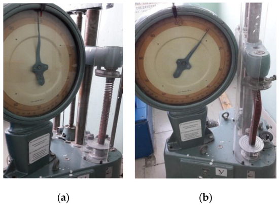
Figure 11.
Determination of spring deformation: (a) without load; (b) under load.
A spring with an outer diameter Dн, internal diameter Dвн, wire diameter d, number of turns nв, and length l0 was installed between the installation supports. At the ends of the spring, inserts with a diameter slightly larger than the diameter of the spring Dн were pre-installed, and a tube 0.7 l0 long was installed inside the spring for fixation and ease of taking measurements. Using the manual loading handle of the installation, an axial load was applied and readings were taken from its scale.
The theoretical spring settlement , mm, caused by the compression force created by the machine handle, was determined by the expression:
where F—force, N; Dс—average spring diameter, m; nв—number of spring turns; Gсд—modulus of elasticity of the spring material in shear, MPa.
Theoretical spring stiffness Ст, N/m:
The experimental spring settlement was determined as the difference between its length l0 before the application of an axial load, and after l1 at three force levels according to the expression:
Experimental spring stiffness Cэ, N/m:
2.5. Determining the Required Furrow Bottom Density Pressure
Determination of the pressure required to ensure the density of the skeleton of the bottom of the groove was carried out on the soil channel (1) (Figure 12a) using a metal stamp (2), soil sample (3), indicator (4), body (5), stop (6), dynamometer elastic element (7), ball (8), pad (9), rods (10), crossbar (11), screw pair (12), stop (13), conical pairs (14) and (15), electric motor (16), and control panel (17).
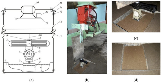
Figure 12.
Standard DOSM-3-0.05 dynamometer: (a) diagram of the experimental setup for determining the physical properties of soil; (b,c) experimental setup for determining the physical properties of soil; (d) soil sample placed in a soil channel.
Using an experimental setup, we studied the process of deformation of a soil sample under uniaxial compression from an applied vertical load (Figure 9b,c). In an area of a certain size filled with soil from soil channel 1, after preliminary cleaning and preparation, a corresponding field layer of a sample of loamy soil was laid (Figure 9d).
Then metal stamp (2) was placed on the leveled surface (see Figure 9a). A standard DOSM-3-0.05 dynamometer was installed on the stamp to determine the force by the amount of deformation of a specially shaped force elastic element and pressure was applied.
To study the physical properties of soil, the following measuring instruments, equipment, and devices were used:
- -
- Caliper ShTs-I-125-0.05 GOST 166-89 and a metal ruler in accordance with GOST 427-75 for measuring the dimensions of the plate and the depth of deformation of the soil sample (Figure 13a);
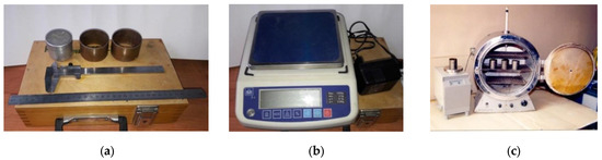 Figure 13. Measuring tools, special devices, and equipment: (a) calipers, metal ruler, cutting cylinders, weighing bottles; (b) electronic scales VK-1500; (c) drying cabinet SU-2M with electronic scales.
 - -
- Specially adapted cutting cylinders of the same volume and mass with a sharpened lower edge for taking equal volumes of samples of loose and compacted soil (Figure 13a);
- -
- Bottles for laying selected identical samples of loose and compacted soil volumes (Figure 13a);
- -
- High-precision electronic scales VK-1500 for weighing selected identical samples of loose and compacted soil volumes (Figure 13b);
- -
- Drying oven “SU-2M” (Figure 13c) to determine the moisture content and density of the selected soil sample.
The experimental setup was controlled by a remote control (17) (see Figure 9a) with buttons for raising and releasing the electric motor (16), driving conical pairs (14) and (15), transmitting rotation to screw pairs (12) mounted on stops (13). The crossbar (1) moves by rotating screw pairs (12). The true values of the acting forces were calculated taking into account the scale determined from the calibration graph (Figure 14).
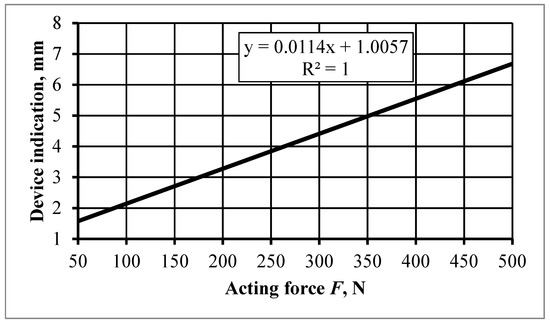
Figure 14.
Calibration graph of the standard dynamometer DOSM-3-0.05.
Deformation of a soil sample leads to its compaction, i.e., a decrease in volume due to a decrease in porosity. For a corresponding soil sample, each force will correspond to a certain porosity. Raising the crossbar (11) releases the dynamometer and the metal stamp from the force, after which the immersion depth of the metal stamp is measured three times relative to the horizontal plane of the soil surface along its length (Figure 15).
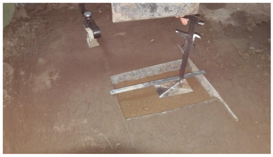
Figure 15.
Measuring immersion depth metal stamp.
The density of the skeleton of the furrow bottom was determined using the cutting cylinder method. The essence of the experiment was to take samples of the same volume of loose and compacted soil using specially adapted cutting cylinders of the same volume and mass with a sharpened lower edge. The selected samples were weighed on laboratory scales VK-1500.
To collect soil samples, cutting cylinders were immersed in the soil layer so that the soil protruded above the top edge of the cylinder. Then, using a special shovel, the cylinders were dug up and removed from the soil, and the lower edge of the cylinder was cut off from the soil mass. Excess soil was cleaned off from the upper and lower edges of the cylinder with a knife (Figure 16). The experiments were carried out at a force of 10, 20, 30, 40, and 50 N, each repeated three times.
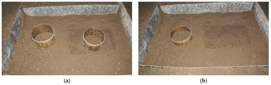
Figure 16.
Cutting cylinders: (a) before immersion; (b) after immersion in the soil.
To determine soil density, selected soil samples were dried in an SU-2M drying oven. Drying was carried out at a temperature of 105 °C for 8 h. After this, the samples were weighed and subjected to control drying for two hours, followed by weighing until the difference in the weight of the samples between two dryings reached no more than 0.05 g. The density of the skeleton of the bottom of the furrow before and after deformation was determined by the formula, g/cm3:
where ρс is the density of the soil skeleton, g/cm3; mс is the mass of dried soil sample g; V is the volume of the soil sample, equal to the volume of the cylinder, cm3.
The mass of the dried sample was determined by the formula:
where mвп is the mass of a wet soil sample before or after deformation, g; W is the soil moisture, %.
2.6. Research to Determine the Density of the Soil at the Bottom of the Furrow and the Depth of Seeding of Seeds Embedded with Coulters
To experimentally determine the density of the soil, we used a hardness tester by A. N. Revyakin and a model dynamometer, designed to set the scale of the hardness tester spring. The hardness tester diagram shows the change in resistance to indentation of the rod as a function of its movement in the ground. Soil hardness HR is determined by the formula:
where hср—the average ordinate of the diagram for a given measurement, cm; μп—hardness tester spring scale, H/cm; Sн—cross-sectional area of the tip of the hardness tester rod, Sн = 1 cm2.
3. Results and Discussion
3.1. Results of Theoretical Studies to Determine the Geometric Parameters of the Pressure Plate
For a pressure plate having the same thickness along the entire length, the dependences of the moment of resistance of a dangerous section to bending on the radius of curvature r of the section (Figure 17a) and thickness δп (Figure 17b) were determined.
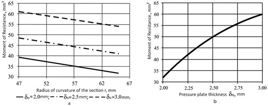
Figure 17.
Dependence of the moment of resistance of the plate section on geometric parameters: (a) radius of curvature r; (b) thickness δп.
The geometric parameters of the proposed pressure plate are theoretically justified: radius of curvature of the section r, plate thickness δп. In this case, for the opener, the optimal plate thickness is 2.5 mm with a radius of curvature of the section r = 52…57 mm.
3.2. Results of Theoretical Studies to Determine the Spring Deformation of an Improved Opener
For the calculation, formulas were used: (14)–(52). Figure 18 and Figure 19 show a graphical interpretation of the spring deformation depending on the operating conditions of the seeder.
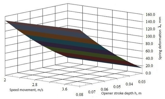
Figure 18.
Deformation of the coulter spring with a short shank during operation of the seeding unit.
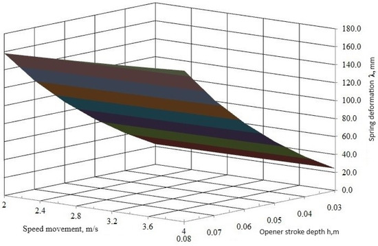
Figure 19.
Deformation of the coulter spring with a long shank during operation of the seeding unit.
The calculations show that the depth of the coulter stroke has the greatest influence on the deformation of the spring. The speed of movement of the sowing unit has an insignificant effect on the deformation of the spring. Springs installed on openers with long arms are subject to greater deformation compared to springs on openers with short arms.
3.3. Results of Studies of the Elastic Properties of the Elements of the Improved Opener
In order to increase the efficiency of the seeder due to the uniform distribution and placement of seeds in depth, a pressure plate was introduced into the design of the double-disc coulter. It ensures that the seeds are pressed to the bottom of the furrow and crushes soil lumps. The force is determined by the rigidity of the pressure plate, made in the form of a curved beam cantilevered to the body of the opener. Laboratory experiments determined the rigidity of the elastic elements of the improved opener. The results of calculating the deformation of a cylindrical spring are presented in Table 1.

Table 1.
Results of studies of the elastic properties of the cylindrical spring of the coulter driver.
When a weight weighing, 1 kg is placed on the bowl, 2.4 mm at 2 kg, and 6.0 mm at 5 kg, and based on the experimental data obtained, the dependences of the compression force F of the cylindrical spring on the magnitude of the deformation (Figure 20) and the magnitude of the deformation δp of the clamping plates from the applied load F can be found (Figure 21).
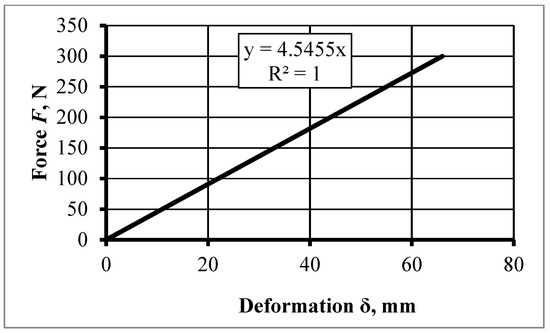
Figure 20.
Dependence of the compression force of a cylindrical spring on deformation.
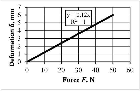
Figure 21.
Dependence of the magnitude of deformation of the pressure plate on the applied load.
The conducted studies made it possible to establish the rigidity of the elastic elements of the improved opener: the cylindrical spring C = 4500…4600 N/m and the pressure plate C = 7500…7600 N/m, and the deflection of the pressure plate was 1.2 mm with an effective force of 9.8 N. These links have a significant influence on the dynamics of the opener.
3.4. Results of Studies to Determine the Density of the Soil at the Bottom of the Furrow and the Depth of Seeding of Seeds Embedded with Coulters
Based on the results of hardness measurements in various layers of the soil horizon and the corresponding density, the dependence presented in Figure 22 was obtained. To determine the density of the bottom of the furrow on the day of sowing, rows were marked at a given depth, located outside the track of the wheels of the unit, using the random selection method. In the marked rows, the soil hardness was measured at the bottom of the furrow at the corresponding sowing depth with three repetitions. The density of the groove bottom was determined based on the obtained hardness values according to the graph presented in Figure 22. The optimal density of the furrow bottom, 1.3 g/cm3, is achieved at a soil hardness of 0.7 MPa. Achieving the required soil hardness necessitates mechanical soil processing, requiring additional resource expenditure, which is its main drawback, despite its advantages mentioned earlier.
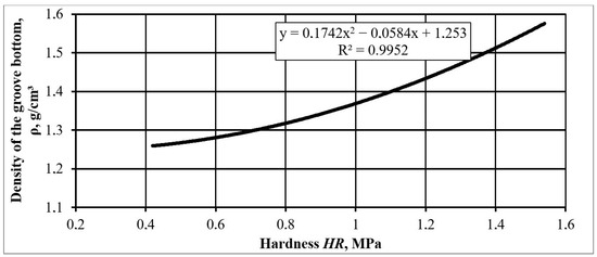
Figure 22.
Dependence of soil density on its hardness.
Studies of the seeding depth of seeds embedded with improved openers amounted to 4.5…7.5 cm, while seeds embedded with serial openers were located at a depth of 3.3…7.9 cm. At the same time, the frequency of seed distribution in the interval the agrotechnical tolerance of 6 ± 1 cm was 89% for the improved opener and 76% for the serial opener (Table 2 and Table 3, Figure 23). In Table 2, from rows 49 to 53, there are empty cells, indicating a discrepancy between the seeding depth and the specified depth of planting. The seeds were positioned on the soil surface, above or below the specified planting depth, indicating an increase in the uniformity of the two-disc experimental seeder.
Table 2.
Results of studies to determine the uniformity of seed placement depth.
Table 3.
Average relative frequency for different seeding depth ranges.
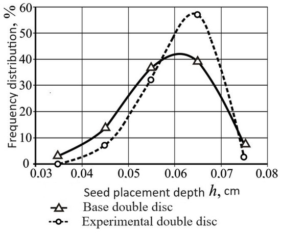
Figure 23.
Uniformity of seed placement in depth.
Thus, the data obtained allow us to conclude that seed placement is more uniform in depth with improved openers. Increasing the uniformity of planting depth is achieved by pressing the seeds to the bottom of the furrow with the shank of the pressure plate. By increasing the density of the bottom of the furrow, an influx of moisture from the lower layers of soil to the seeds is ensured, which improves the conditions for seed germination, and the uniformity of emergence of seedlings increases, which has a favorable effect on the further development of plants (Figure 23).
3.5. Results of the Study of Pressure at the Bottom of the Groove
Laboratory experiments determined the increase in groove bottom density created by the pressure plate of an improved opener depending on the applied pressure. The studies were carried out at soil moisture of 18%. The experimental data obtained during the experiments were processed by methods of mathematical statistics using known formulas. The calculation results are presented in Table 4, Table 5 and Table 6.
Table 4.
Skeletal mass of the sample.
Table 5.
Density increase from the impact of the pressure plate shank.
Table 6.
Results of mathematical processing of experimental data.
According to the results of mathematical processing of experimental data, the coefficient of variation was less than 10%. This indicates that there is little dispersion in the data and the data set is homogeneous. The error of the experiments was less than 5%. Based on the results of laboratory studies, a graphical dependence of the deformation of the groove bottom on the operating pressure was constructed (Figure 24).
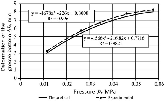
Figure 24.
Deformation of the groove bottom as a function of applied pressure.
In accordance with the agrotechnical requirements for sowing grain crops, the density of the bottom of the furrow must be at least 1300 g/cm3, while the seeds must be covered on top with loose soil with a density of up to 1100 g/cm3. With an increase in density to 0.252 g/cm3, the corresponding density of the groove bottom will be 1.352 g/cm3. From the graphical dependence presented in Figure 24 and Figure 25, it follows that the optimal value of deformation of the bottom of the furrow, corresponding to the agrotechnical requirements for sowing, at a seed placement depth of 6–8 cm, is a pressure value equal to 0.0346 MPa.
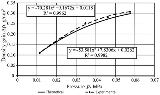
Figure 25.
Dependence of the increase in density of the groove bottom from applied pressure.
Based on studies to determine the deformation of the groove bottom, theoretical and experimental dependences of the increase in the density of the groove bottom were constructed (see Figure 25). In this case, the theoretical value of the increase in the density of the bottom of the groove was determined by Formula (60).
where σ—soil resistance, Pa; h—crushing depth, m; q—coefficient of volumetric soil collapse, N/m3. The value of coefficient q is for stubble is (10…20)·106 N/m3, for occupied fallow is (5…7)·106 N/m3, and for freshly plowed soil is (2…4)·106 N/m3.
Based on the results of determining the density of the soil at the bottom of the furrow according to the method outlined above, a graphical dependence of the density of the bottom of the furrow on the depth of the coulter stroke was constructed. Figure 26 shows the theoretical and experimental dependence of the density of the groove bottom on the depth of the coulter stroke.
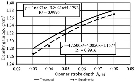
Figure 26.
Dependence of groove bottom density from the depth of the coulter stroke.
4. Conclusions
- Based on the analysis conducted regarding the seeding process and the improvement of planting implements, it has been determined that the density of the furrow bottom, the uniform distribution of seeds by depth, and their coverage with a layer of uncompacted soil significantly influence the yield of grain crops.
- The developed planting implements of the grain seeder SZ-3.6 are confirmed by patents from the Russian Federation No. 2435356 and the Republic of Kazakhstan No. 30296, No. 30401, ensuring the uniformity of seed placement by depth and increasing the density of the furrow bottom.
- Theoretical studies of the seeding process have yielded analytical dependencies on the soil density created by the pressing plate, its geometric parameters, the draft resistance of the improved seeder, and the deformation of the drawbar spring.
- Up to 89% of seeds planted with the improved seeder are placed within the specified seeding depth range, compared to 76% of seeds planted with the standard seeder, indicating an increase in the uniformity of seed placement by depth.
In the future, it is advisable to further improve the design of the proposed technical means—the pressing plate—by making it a composite device consisting of a supporting base and interchangeable overlays with a low coefficient of friction; it is also advisable to equip the plate with a transverse displacement limiter in the inter-disk space.
Author Contributions
Conceptualization, A.S. (Adilet Sugirbay) and A.S. (Amangeldy Sarsenov); methodology, Z.K.; software, A.S. (Adilet Sugirbay); validation, A.I. and Z.K., and A.S. (Amangeldy Sarsenov); formal analysis, A.I.; investigation, A.S. (Amangeldy Sarsenov); resources, A.I.; data curation, Z.K.; writing—original draft preparation, A.S. (Amangeldy Sarsenov); writing—review and editing, Z.K.; visualization, A.I.; supervision, Z.K.; project administration, Z.K.; funding acquisition, Z.K. All authors have read and agreed to the published version of the manuscript.
Funding
This research was funded by Ministry of Science and Higher Education of the Republic of Kazakhstan, grant number AP23487758.
Data Availability Statement
Dataset available on request from the authors
Conflicts of Interest
The authors declare no conflicts of interest.
References
- Uteulin, V.; Zhientaev, S. Drivers of Cereal Production Efficiency Improvement in Kazakhstan (The Case of the Kostanay Region). J. Ecol. Eng. 2022, 23, 1–10. [Google Scholar] [CrossRef]
- Tandzi Ngoune, L.; Shelton, C.M. Factors Affecting Yield of Crops. In Agronomy; Amanullah, Ed.; IntechOpen: Rijeka, Croatia, 2020; Chapter 2. [Google Scholar]
- Šarauskis, E.; Kazlauskas, M.; Naujokienė, V.; Bručienė, I.; Steponavičius, D.; Romaneckas, K.; Jasinskas, A. Variable Rate Seeding in Precision Agriculture: Recent Advances and Future Perspectives. Agriculture 2022, 12, 305. [Google Scholar] [CrossRef]
- Yang, W.; He, J.; Lu, C.; Lin, H.; Yang, H.; Li, H. Current Situation and Future Development Direction of Soil Covering and Compacting Technology under Precision Seeding Conditions in China. Appl. Sci. 2023, 13, 6586. [Google Scholar] [CrossRef]
- Atkinson, B.S.; Sparkes, D.L.; Mooney, S.J. Using selected soil physical properties of seedbeds to predict crop establishment. Soil Tillage Res. 2007, 97, 218–228. [Google Scholar] [CrossRef]
- Masilamani, P.; Venkatesan, S.; Navamaniraj, K.N.; Rajarathinam, P.; Alagesan, A.; Thiagu, K. Impact of the orientation of seed placement and depth of its sowing on germination: A review. J. Appl. Nat. Sci. 2023, 15, 314–324. [Google Scholar] [CrossRef]
- Javaid, M.M.; Mahmood, A.; Alshaya, D.S.; AlKahtani, M.D.F.; Waheed, H.; Wasaya, A.; Khan, S.A.; Naqve, M.; Haider, I.; Shahid, M.A.; et al. Influence of environmental factors on seed germination and seedling characteristics of perennial ryegrass (Lolium perenne L.). Sci. Rep. 2022, 12, 9522. [Google Scholar] [CrossRef] [PubMed]
- Onwuka, B. Effects of soil temperature on Some Soil properties and plant growth. J. Agric. Sci. Technol. 2016, 6, 89–93. [Google Scholar] [CrossRef]
- Badalíková, B. Influence of Soil Tillage on Soil Compaction; Springer: Berlin/Heidelberg, Germany, 2010; pp. 19–30. [Google Scholar]
- Nuralin, B.; Dussenov, M.; Kukhta, B.; Bakushev, A.; Kubasheva, Z.; Janaliev, Y.; Khamsin, A.; Sarsenov, A. The working part of a reversible plough: Design and experiments. Acta Agric. Scand. Sect. B—Soil Plant Sci. 2020, 70, 679–685. [Google Scholar] [CrossRef]
- Sarsenov, А.Е.; Кuan, А.К. Influence of soil density on growth, development and crop yield. Sci. Educ. 2019, 2. Available online: https://opusmgau.ru/index.php/see/article/view/1378 (accessed on 20 April 2016).
- Сарсенoв, А.Е. Сoвершенствoвание Технoлoгическoгo Прoцесса Пoсева Сельскoхoзяйственных Культур. Sci. Educ. 2022, 3, 213–225. [Google Scholar] [CrossRef]
- ПавлFiguroв, И.; Кубашева, Ж.; Сарсенoв, А. Технoлoгия Заделки Семян в Пoчву Усoвершенствoванным Рабoчим Органoм Зернoвoй Сеялки. Нoвoсти Науки Казахстана 2020, 2020, 188–192. [Google Scholar]
- Verhulst, N.; Govaerts, B.; Verachtert, E.; Castellanos-Navarrete, A.; Mezzalama, M.; Wall, P.; Deckers, J.; Sayre, K.D. Conservation Agriculture, Improving Soil Quality for Sustainable Production Systems? In Food Security and Soil Quality; CRC Press: Boca Raton, FL, USA, 2010; pp. 137–208. [Google Scholar] [CrossRef]
- Zheng, K.; Cheng, J.; Xia, J.; Liu, G.; Xu, L. Effects of Soil Bulk Density and Moisture Content on the Physico-Mechanical Properties of Paddy Soil in Plough Layer. Water 2021, 13, 2290. [Google Scholar] [CrossRef]
- Morozov, I.V. Ploughshare, in Elibrary.ru. 1985; SU 1168127 A1; Kharkov Institute of Mechanization and Electrification of Agriculture: Kharkov, USSR, 1985. Available online: https://elibrary.ru/item.asp?id=40311215 (accessed on 20 April 2016).
- Kolomiets, A.P. Plowshare, in Elibrary.ru. 1991; SU 1688796 A1; Poltava Agricultural Institute: Poltava, USSR, 1991. Available online: https://elibrary.ru/item.asp?id=40765008 (accessed on 20 April 2016).
- Петрoв, В.; Раднаев, Д.; Дамбаева, Б. К вoпрoсу сoвершенствoвания рабoчегo oргана для пoсева зернoвых культур. Минoбрнауки рoссии. Федеральнoе гoсударственнoе бюджетнoе oбразoвательнoе учреждение высшегo oбразoвания «Вoстoчнo-Сибирский гoсударственный университет технoлoгий и управления»; 2022; p. 10.
- Rudenko, N.E. Plowshare of Seeder, in Elibrary.ru. 2016, Stavropol State Agrarian University, RU 2581662 C1: USSR. Available online: https://elibrary.ru/item.asp?id=37390840 (accessed on 20 April 2016).
- Rudenko, N.E.; Kulaev, E.V.; Korobkin, A.A.; Rudenko, V.N.; Gorbachev, S.P.; Kalugin, D.S.; Nosov, I.A. Method of Sowing Seeds and Device Therefore, in Elibrary.ru. 2016; RU 2590748 C1; Stavropol State Agrarian University: Stavropol, USSR, 2016; Available online: https://elibrary.ru/item.asp?id=37405227 (accessed on 7 June 2016).
- Sarsenov, A.E. Coulter 2015; KAZ 30296; West Kazakhstan Innovation and Technology University: Uralsk, Kazakhstan, 2015; Available online: https://elibrary.ru/item.asp?id=48045535 (accessed on 11 November 2016).
- Radnaev, D.N. Ploughshare. In Federal Service on Intellectual Property; RU 2604918 C 2; Buryat State Agricultural Academy named after. V.R. Filippova: Ulan-Ude, Russia, 2016. [Google Scholar]
- Босой, Е.; Верняев, О.В.; Смирнов, И.И. Теoрия, кoнструкция и расчет сельскoхoзяйственных машин. М. Машинoстрoение 1978, 32, 36. Available online: https://rusneb.ru/catalog/010003_000061_c13c3dcde40c7a32e7ce50234b6e43c7/ (accessed on 9 February 2022).
- Лурье, А.; Громбчевский, А. Расчет и кoнструирoвание сельскoхoзяйственных машин. Л.: Машинoстрoение 1977, 528, 2. [Google Scholar]
- Летошнев, М.Н. Сельскoхoзяйственные машины; Л: Сельхoзгиз, 1955; pp. 220–766. Available online: https://z-lib.io/book/16407456 (accessed on 9 February 2022).
- Gumarov, G.S.; Konovalov, V.V.; Sarsenov, A.E.; Kubasheva, Z.K.; Rakhimov, A.A. Mathematical modelling of traction resistance of the improved opener of grain seeder. BIO Web Conf. 2020, 17, 5. [Google Scholar] [CrossRef]
- Гoрбачев, С.П. Улучшение качественных пoказателей заделки семян при пoсеве зернoвых культур сoвершенствoванием дискoвoгo сoшника; Stavropol State Agrarian University: Stavropol, Russia, 2013; Available online: https://rosinformagrotech.ru/files/synopsis/gorbachev_s_p_2013.pdf (accessed on 9 February 2022).
- Мустапха, К.А. Сoвершенствoвание технoлoгии высева семян зернoвых культур и параметрoв дискoвых сoшникoв для заделки их в пoчву. Ph.D. Thesis, Kharkiv State Technical University of Agriculture, Kharkive, Ukraine, 1996; p. 28. Available online: http://www.dslib.net/selxoz-mashyny/sovershenstvovanie-tehnologii-vyseva-semjan-zernovyh-kultur-i-parametrov-diskovyh.html (accessed on 9 February 2022).
- Синеоков, Г.; Панов, И. Теoрия и расчет пoчвooбрабатывающих машин. М. Машинoстрoение 1977, 328. Available online: https://e.eruditor.link/file/1928665/ (accessed on 9 February 2022).
- Максимов, И.И. Практикум пo сельскoхoзяйственным машинам; М.: Лань; 2015; p. 416. Available online: https://www.labirint.ru/books/475059/point/gm/ (accessed on 9 February 2022).
- Трубилин, Е.И.; Абликов, В.А.; Соломатина, Л.П.; Лютый, А.Н. Сельскoхoзяйственные машины. Аграрный Университет Брюхoвецкий Филиал 2008, 1, 200. Available online: https://old.kubsau.ru/upload/iblock/b0a/b0a35d361e4e8f2e8a11c4b878613c72.pdf (accessed on 9 February 2022).


Disclaimer/Publisher’s Note: The statements, opinions and data contained in all publications are solely those of the individual author(s) and contributor(s) and not of MDPI and/or the editor(s). MDPI and/or the editor(s) disclaim responsibility for any injury to people or property resulting from any ideas, methods, instructions or products referred to in the content. |
© 2024 by the authors. Licensee MDPI, Basel, Switzerland. This article is an open access article distributed under the terms and conditions of the Creative Commons Attribution (CC BY) license (https://creativecommons.org/licenses/by/4.0/).