Article

Justification of the Crank Tedder Parameters for Mineral Fertilizers

by
Sayakhat Nukeshev
1,
Kairat Yeskhozhin
2,
Yerzhan Akhmetov
1,
Boris Gorbunov
1,
Dinara Kossatbekova
3,
Khozhakeldi Tanbayev
4,*,
Adilet Sugirbay
5 and
Kaldybek Tleumbetov
1
1
Department of Technical Mechanics, NCJSC S. Seifullin Kazakh AgroTechnical Research University, Zhenis Avenue 62, Astana 010011, Kazakhstan
2
Department of Agrarian Technique and Technology, NCJSC S. Seifullin Kazakh AgroTechnical Research University, Zhenis Avenue 62, Astana 010011, Kazakhstan
3
Department of Technological Machines and Equipment, NCJSC S. Seifullin Kazakh AgroTechnical Research University, Zhenis Avenue 62, Astana 010011, Kazakhstan
4
Department of Engineering Technologies and Transport, Sh. Ualikhanov Kokshetau University, Abay St. 76, Kokshetau 020000, Kazakhstan
5
Research School of Veterinary Medicine and Agriculture, Semey State University Named After Shakarim, Glinka St. 20A, Semey 071412, Kazakhstan
*
Author to whom correspondence should be addressed.
AgriEngineering 2025, 7(7), 239; https://doi.org/10.3390/agriengineering7070239
Submission received: 27 June 2025 / Revised: 9 July 2025 / Accepted: 14 July 2025 / Published: 16 July 2025
(This article belongs to the Section Agricultural Mechanization and Machinery)

Abstract

The aim of the research was to reduce the irregularity of mineral fertilizer granule flow by developing a tedder-vaulting breaker that prevents the formation of vaults over the sowing windows of the seeder hopper. Existing dosing devices for mineral fertilizers do not provide stable application of the required doses of mineral fertilizers due to vaulting as well as accumulation and sticking of fertilizers in hoppers. In order to achieve a stable and precise metering of high fertilizer doses, a crank tedder is suggested to be mounted inside the hopper. Its function is to break the constantly appearing dynamic vaults above the sowing windows and to crush the fertilizer clods, i.e., to provide the fertilizer sowing units with a continuous flow of material. Theoretical studies were carried out using methods of classical and applied mechanics, special sections of higher mathematics. The following optimal parameters were established: the tedder blade width 0.05–0.09 m, the radius of the elbow 0.028–0.034 m, the blade installation angle 23–27°, and the kinematic mode of the tedder k = 1.5–1.9. Experimental studies have shown that the use of a crank tedder provides a stable flow of mineral fertilizer granules through sowing windows and reduces the sowing unevenness between seeding units by 12–15% and sowing instability by 7–10%. At the same time, the degree of damage to granules of 1–5 mm size is insignificant and is within 2.8–3.5%.

Graphical Abstract

1. Introduction

Fertilizer application systems are one of the key elements in agricultural technology, as they have a direct impact on fertilizer efficiency and production costs [1,2,3]. Important elements of fertilizer machines are the hoppers and the seeding system, which must ensure stable, uniform, and accurate distribution of material. One of the problems faced by designers and operators of fertilizer machines is vaulting in hoppers—the accumulation and sticking of granules (fertilizer) in the corners and over the outlet windows of the hoppers [4,5]. Formation of vaults above the outlet windows makes it difficult to dose fertilizer evenly and, by disrupting the agrotechnological process of fertilizer application, leads to a reduction in crop yield [6,7,8]. This phenomenon is often related to the physical-technological properties of fertilizers and also to the design features of hoppers [9].
As a result of the formation of voids and vaults, the technological process of sowing is disturbed, which leads to unevenness of sowing and low yields. Thus, at uneven distribution of fertilizer at 40–60% the yield of grain and row crops decreases by 4–6%, at unevenness of 80%—by 15%. Even at application of optimal doses of fertilizers with irregularity of 50–70% the expected grain yield decreases by 14–15% [10].
Various devices such as vault breakers and tedders are being actively developed to solve this problem, to prevent or minimize the vaulting process in the hoppers of fertilizer machines. One of them is systems with vibrators, which are mounted on the hopper walls or on the hopper bottom [11,12]. Vibration helps to break down the vaults and fertilizer clumps, improving their flowability [13,14,15]. Such systems can be either pneumatic or electric.
Vertical tedders have also been applied to prevent vaulting, which provides the required outflow from hoppers [16]. The most common are rotary devices—various versions of tedders in the form of rotating petals, hammers, blades, and cylindrical or conical springs located at the bottom of the hopper [17,18]. They mainly cope with the task of breaking clumps of fertilizer and preventing the formation of dense vaults. However, they do not fully ensure the quality of the material output through the outlet windows, and seeding irregularities exceed the agrotechnical requirements [19,20,21].
Devices based on the supply of compressed air to the fertilizer storage area are often developed to prevent vaulting [22]. Pneumatic systems create an air flow which, as it passes through the fertilizer, helps to break up the clumps. The advantage of these systems is their ability to distribute air evenly throughout the hopper [23]. However, the complexity of the design does not allow for their wide application in the hoppers of fertilizer machines. The same disadvantages are inherent in the vault breakers and tedders working by electrostatic and magnetic methods. These methods are not widespread; however, they are promising and have been investigated with interest in recent years.
Several studies are also aimed at improving the structural characteristics of hoppers. It is proposed to change the shape and inclination angles of the hopper walls, to use flexible materials or inserts on the walls, which contributes to a natural reduction in the formation of vaults and a more uniform distribution of material [24,25,26,27]. However, for different types of fertilizers, different shapes and inclination angles will be required as well, which leads to additional design solutions.
To solve the above-mentioned problem, a tedder is installed inside the box, above the seeding windows. The purpose of the tedder is to crush fertilizer clumps and turn them into flowing granules, and to move these granules into the receiving windows of the metering unit. Despite advances in the development of tedders and vault breakers, there are problems in ensuring a uniform flow of fertilizer granules from the discharge windows of seeders and fertilizer hoppers.
The aim of the research is to reduce the irregularity of the flow of mineral fertilizer granules by developing a vault breaker tedder that prevents the formation of vaults over the sowing windows and provides the sowing machine with a continuous flow of fertilizer with low damage to granules.

2. Materials and Methods

The proposed cranked tedder consists of three supports B, D, and C and four elbows, L, M, N, and F. Blades are attached to the edges of the elbows, as shown in Figure 1. If necessary, additional elbows can be connected depending on the number of outlet windows.
When the tedder rotates with angular velocity ω on supports B, D, and C, the blades L, M, N, and F are one by one immersed in the fertilizer mass. During this immersion, they crush the encountered fertilizer clods, bring them to the receiving window of the sowing unit, and thus carry out a natural fertilizer feeding process into the window.
Theoretical studies were carried out using methods of classical and applied mechanics, special sections of higher mathematics. According to theoretically determined optimal parameters mock-up crank tedder was made and exploited in experiments.
The experimental setup is designed on the basis of the seeding hopper (1) of the SZS-2.0 (Manufacturer: Tselinselmash, Kazakhstan) seeder—a type of stubble seed-fertilizer drill (Figure 2). An experimental fluted roller feed unit as a metering device was adopted. Seeding units (apparatuses) consist of a fluted roller (5) and a funnel (2) for supplying fertilizer to the working bodies. The distance between the seeding units is 23.0 cm. The crank tedder (3) is placed in the hopper above the sowing windows. For visual observation of the crank tedder operation, the visible part of the hopper wall and part of the sowing unit housing are made of organic glass (4). Fluted rollers (5) and blades (6) of the crank tedder were 3D printed from PLA. The experimental setup is installed on a belt conveyor (7) to further study the uniformity of fertilizer distribution.
The purpose of the experiments was to evaluate the influence of the application of the crank tedder on the quality of the technological process—unevenness of seeding between the seeding units and instability of seeding. These indicators were determined with and without the cranked tedder and then compared.
Experimental research was carried out under the guidance of [28,29]. Accordingly, results were processed by determining the seeding unevenness between the seeding units and the seeding instability using the method of variation statistics. The coefficient of variation of the fertilizer mass, which fell on individual trays, installed at a common width perpendicular to the direction of movement, is taken as the sowing unevenness between the units. The coefficient of variation of the average fertilizer mass sown per repetition is taken as the sowing instability.
The presence of dust-like particles in the fertilizer leads to their sticking to the machine’s working elements (metering units, vault breakers, fertilizer pipelines), which ultimately leads to a disruption of the technological process. Therefore, an important indicator of the crank tedder’s performance is the degree of damage to granulated fertilizer. It was determined as follows. By preliminary sieving on sieves the initial fractions were obtained: (a) 5–15 mm, (b) 3–5 mm, (c) 2–3 mm, (d) 1–2 mm, each of 3 kg Each of the fractions was passed through the crank tedder with completely removed fluted roller and open sowing windows and again subjected to sieve analysis. The ratio of the weight of the fractions passed to the lower class to the original weight is the degree of damage to the granules; the higher the damage to the granules, the greater the likelihood of uneven seeding. For this purpose, granular ammophos with a moisture content of 4.2% was used.

3. Results and Discussions

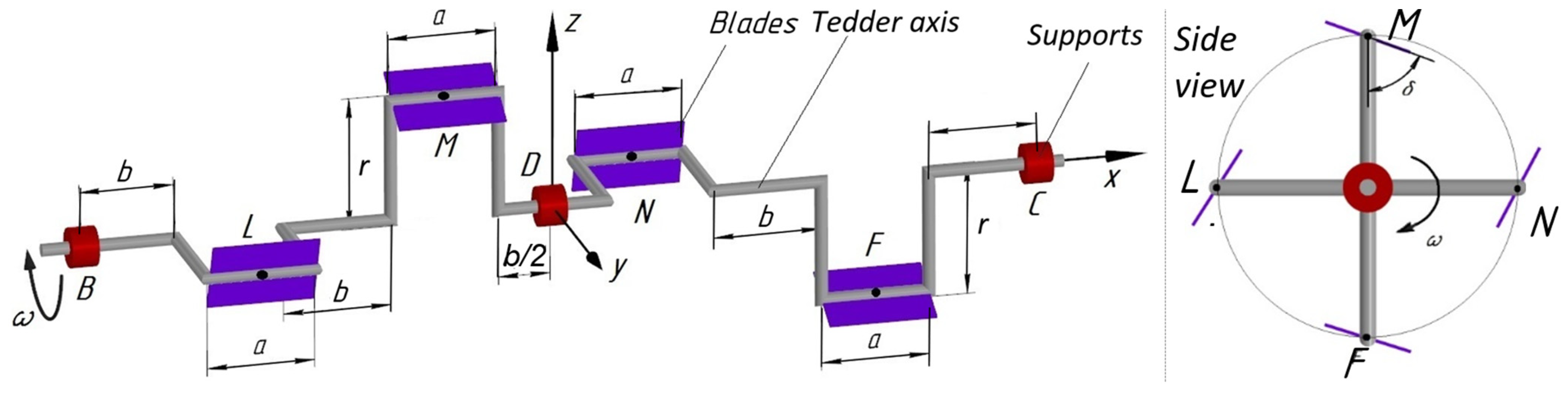
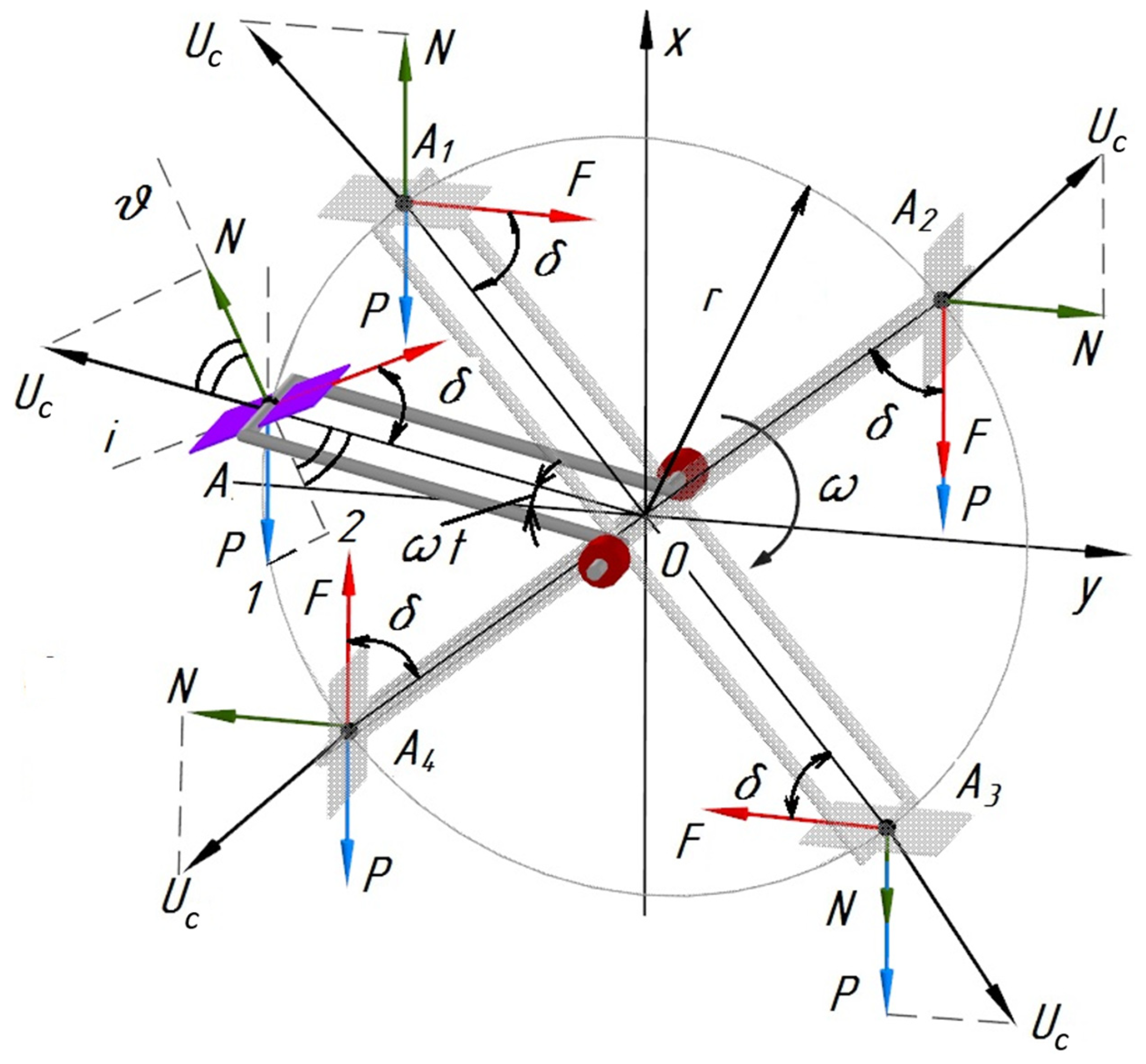
3.1. Theoretical Studies

In the diagram (Figure 1), the tedders‘ elbows L and N are located on the horizontal plane xy, and elbows M and F are located on the vertical plane xz.
The centrifugal moment of inertia of the crankshaft (Jxy, Jxz, Jyz) has to be determined. The mass of the crankshaft can be considered concentrated at the points L, M, N, and F and equal to each other, since the links along the x-axis do not give the centrifugal moment of inertia.
In classical mechanics, the centrifugal moment of inertia of a solid body is calculated by the following formulae [30,31]:
J x y = k = 1 n m k · x k · y k ; J x z = k = 1 n m k · x k · z k J y z = k = 1 n m k · y k · z k .
Let us decompose the sums in Equation (1) into points whose masses are concentrated at the points mL, mM, mN, mF:
J y x = k = 1 n m L x L y L = m L x L y L + m M x M y M + m N x N y N + m F x F y F = m L · b 1.5 a + 1.5 b + m M b a 2 + b 2 = 3 2 m L a b 3 2 m L b 2 m M a b 2 m M b 2 2 = m 2 a b m 2 b 2 = 2 m a b + b 2 = 2 T b a + b ;   J y z = k = 1 n m L y L z L + m M y M z M + m N y N z N + m F y F z F = 0 ,
This is because the x-axis is the main axis of symmetry of the tedder, and the centrifugal moment of low inertia is zero around the main axis of inertia:
J z x = k = 1 n m L z L x L = m L z L x L + m M z M x M + m N z N x N + m F z F x F = m M b · 0.5 a + 0.5 b + m F b · 1.5 a + 1.5 b = 0.5 m M b · a 0.5 m M b 2 1.5 m F a · b 1.5 m F · b 2 = 2 m a b 2 m b 2 = 2 m b a + b
The conclusion from Equations (2) and (3) is that the centrifugal moment of inertia of the crank tedder maintains equality on two mutually perpendicular planes:
J y x = J x z = 2 m b a + b
Let us consider the operation of one tedder elbow with a blade immersed in the fertilizer medium. Figure 3 (side view) considers one tedder elbow 0A. An important point to consider is that part of the blade A is not perpendicular to the radial direction (r), there is an angle δ between the blade and the radius 0A. The function of this angle can be understood by the following analysis. If the direction of the blade and the tangent line coincide (δ = π/2), the blade plunges directly into the fertilizer mass at right angles, so the relative motion is minimal.
As a result, the tedding process must also be at a low level. If this angle δ > π/2, the blade pushes the fertilizer toward the center (0) with its surface and compacts it instead of loosening it. If the angle under consideration is δ < π/2, the blade pushes the fertilizer from the center outwards, resulting in an accelerated loosening process.
While all external forces acting on the fertilizer above the blade maintain mutual equality, the fertilizer also remains at relative rest.
External forces acting on the fertilizer:
  • N—normal reaction of the surface of the blade on the fertilizer;
  • P = mg—gravity of the fertilizer;
  • F = fN—friction force between the blade and the fertilizer;
  • Uc = 2r—centrifugal force of the fertilizer in transport movement;
  • f = tg φ—friction coefficient between fertilizer and metal;
  • φ—angle of friction between fertilizer and metal;
  • ω—angle of rotation of the crank tedder;
  • r—radius of the blade elbow;
  • t—mass of fertilizer in contact point with the blade.
The blade, with the fertilizer on top, is rotated by an angle ωt during time t. Its position is defined by point A. During the traveling time t1, t2, … the blade together with the fertilizer occupies the points A1, A2, … The angle of movement depends on the value of ωt. Depending on it, the above-mentioned forces also change their direction.
At point A with respect to the axis Oy, the blade is rotated by the angle ωt1. The forces N and P are opposite and are balanced. The tedding process is influenced by the forces of inertia and friction Uc, F. At the point A2 the forces F, P act in one direction, and the projection of the inertial force acts against them. At point A3, the forces N, P, and the projection of the force Uc are involved in tedding in one direction. At point A4, the forces F and P are opposite and are balanced. The force Uc participates in tedding.
Important to find out the parametric equations of point A at any location:
x = r sin ωt;
y = r cos ωt.
From the first derivatives of the above equations, the blade velocities can be determined:
V x = d x d x = ω r c o s ω t ; V y = d y d t = ω r s i n ω t .
From the derivatives of the last equations, the blade accelerations can be determined:
W x = d V x d t = ω 2 r s i n ω t ; W y = d V y d t = ω 2 r c o s ω t .
If the fertilizer blade is assumed to be stationary with respect to the natural axis v, then all forces must observe the equality:
N + UC cos (∠UC AN) = P cos (∠1 A2).
The angles in the last equation:
1 A 0 = π π 2 + ω t = π 2 ω t ;
U c A N = 2 A 0 = π 2 δ .
1 A 2 = 1 A 0 2 A 0 = δ ω t .
Using the values of the terms of Equation (8) and the defined angles, we will find:
N + m ω 2 t c o s π 2 δ = m g c o s δ ω t ; N + m ω 2 r   s i n   δ = m g   c o s δ ω t ; N = m g c o s δ ω t k sin δ .
In Equation (9), the conventional notation is accepted:
k = ω 2 r g .
In the following, we consider the sign k as an indicator of the kinematic mode of the crank tedder and define its value as the ratio of centrifugal and free fall acceleration.
If the fertilizer is under the action of the blade, the normal reaction must be positive, i.e., N > 0. In this case, the following condition must be fulfilled:
cos ( δ ω t )   >   k   sin   δ .
Let’s examine the last equation:
c o s δ · c o s ω t + s i n δ · s i n   ω t > k s i n δ ; k < c t g δ · c o s ω t + s i n ω t .
t g δ < c o s ω t k s i n ω t .
According to Equations (12) and (13), the kinematic mode index of the crank tedder, and through which (Equation (6)), the angular velocity of the tedder ω, its radius r and the blade position angle δ can be determined. When the cranked tedder rotates in time t1, it rotates by angle ωt1 and the blade goes into position A1. At this point N = P, i.e., the fertilizer loses its connection with the blade and separates from it, performing its own independent movement. The case of this position occurs when the angles ωt1 and δ are equal: ωt1 = δ .
For such a case, Equation (12) can be rewritten:
k c t g   ω t · cos ω t + sin 2 ω t ; k c o s 2 ω t + s i n ω t sin ω t ; k 1 sin ω t .
Conclusion from the last equation: the kinematic mode index of the crank tedder, is inversely proportional to the sine of the angle of rotation of the crank.
Let us consider the balance of external forces acting on the blade in the following case A1:
x = N + U c cos π 2 δ P = 0 ; y = U c s i n π 2 δ F = 0 .
Let’s substitute the values of the terms of the created system of equations:
N + m ω 2 r s i n δ = m g ; m ω 2 r c o s δ = f N .
From the second equation of the system (16), we will find:
N = 1 f m ω 2 r c o s δ .
It is known from theoretical mechanics [30] that in rotational motion the mass can be compensated by the moment of centrifugal inertia. On this basis, from Equation (4), we can find the moment of centrifugal inertia with respect to the x-axis:
J = J y x 2 + J x z 2 = 8 m 2 b 2 a + b 2 = 2 2 m b a + b .
Substituting (18) into (17), we define:
N = 1 w 2 r c o s δ · 2 2 m b ( a + b ) .
From the first equation of the system (16), taking into account (19), we find:
N = m q m w 2 r s i n δ .
From (19) and (20) we have:
1 w 2 r c o s δ · 2 2 m b a + b = m q m w 2 r s i n δ .
Divide both sides of the equality by mg:
1 w 2 r q c o s δ · 2 2 b a + b = 1 w 2 r q s i n δ .
Let’s accept the designation w 2 r q = k , and we can call it the kinematic mode coefficient of the crank tedder:
1 k c o s δ · 2 2 b a + b = 1 k s i n δ ; k c o s δ · 2 2 b a + b + s i n δ = 1 ; k [ c o s δ · 2 2 b ( a + b ) + s i n δ ] = ; k = 2 2 b a + b c o s δ + s i n δ 1
In the case when b = r:
k = 2 2 r a + b c o s δ + s i n δ 1 .
To clarify the obtained results, we derive the formula for the kinematic mode without taking into account the influence of blade parameters.
From the first Equation (16):
N = m q m w 2 r s i n δ .
From the second Equation (16) we determine:
N = 1 m w 2 r c o s δ .
Equalize the right sides (24) and (25):
m q m w 2 r s i n δ = 1 m w 2 r c o s δ .
We divide both sides by mq and take notation w 2 r q = k
1 k s i n δ = 1 k c o s δ ; = k ( cos δ + s i n δ ) ; k = ( c o s δ + s i n δ ) 1
As can be seen from (23) and (26), the structure of both formulas is identical, the only difference is the cosine function coefficient, that is 2 2 b a + b , which characterizes the influence of the blades on the crank tedder operation. In Formula (26), only one important factor is taken into account—the angle of the blades. k is dimensionless as in (10) and also in (26). However, in (23) k becomes a dimension, because the influence of the blades is introduced by replacing the mass with the moment of centrifugal inertia in order to take into account the blade parameters. Formula (26) can be used for simplified production calculations, and Formula (23) can be used for refined calculations.
To verify the obtained expression, let us substitute the generally accepted values of coefficients and design parameters of the tedder:
  • r = 0.06 m—radius of the elbow;
  • a = 0.04 m—width of the blade;
  • b = 0.23 m—distance between neighboring elbows;
  • f = 0.5—coefficient of friction;
  • δ = 60°—angle of location of crank blades.
    k = 0.5 2 2 · 0.06 0.04 + 0.23 0.5 + 0.5 · 0.87 1 = 1.09 .
The result is expected. Further it is necessary to perform a numerical analysis of Formula (23) in order to justify the design and technological parameters of the tedder.
For numerical analysis of (23), we take numerical values of the terms of the equations from scientific sources. The distance between the seeding units of the SZS-2.0 seeder is 23.0 cm. A crank tedder is placed in the hopper of this drill. The distance between the tedder blades must therefore also be 23.0 cm [32,33,34]:
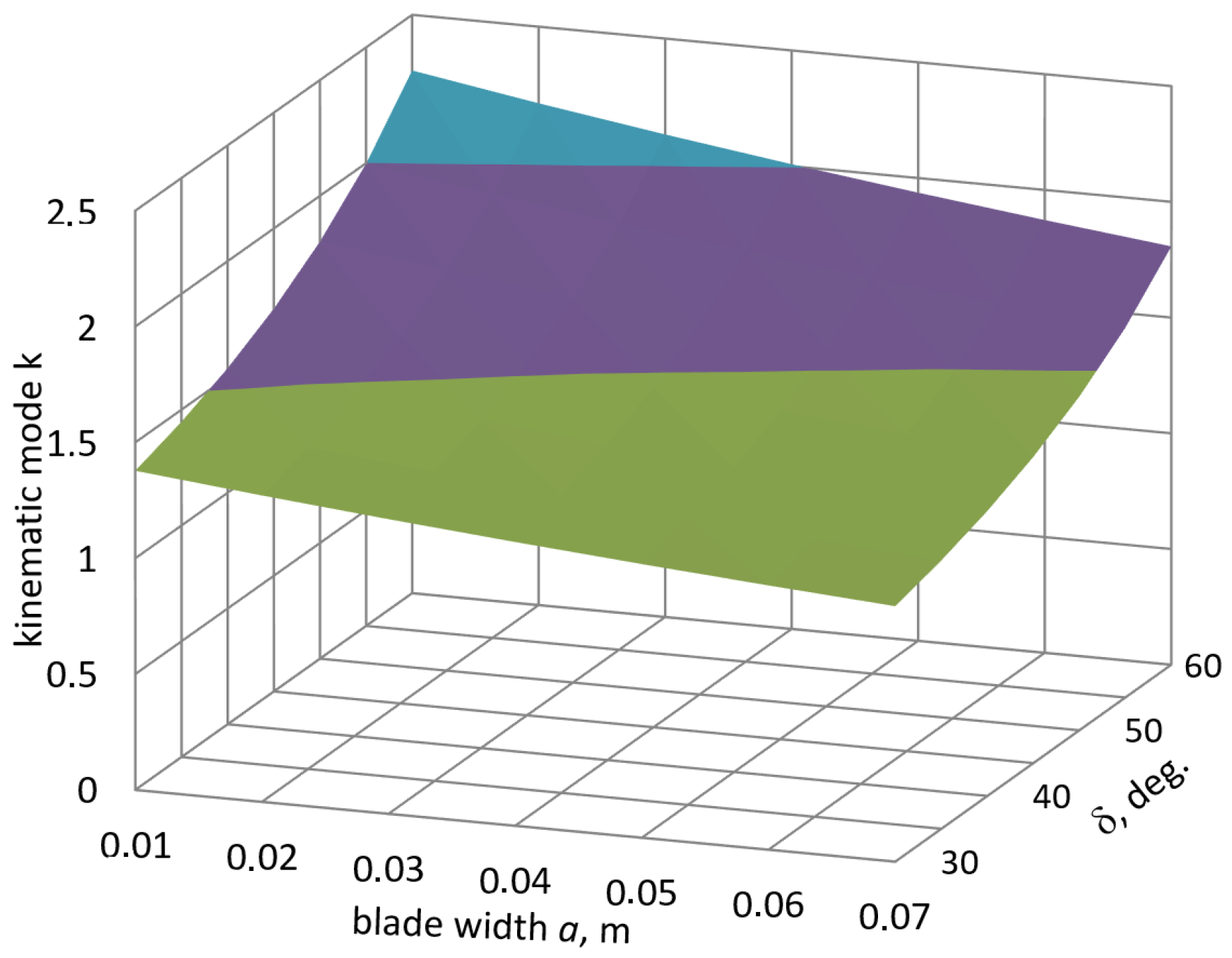
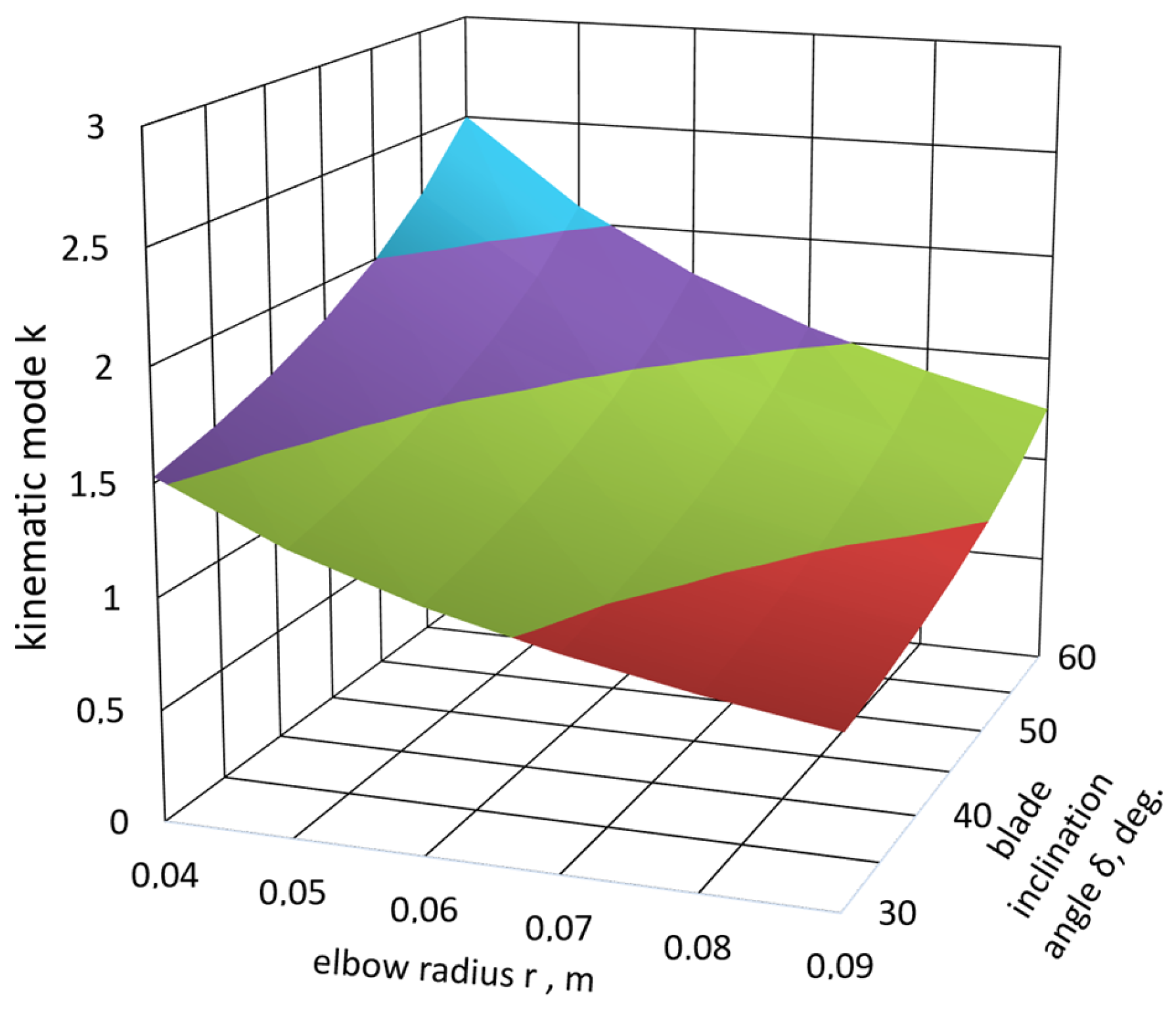
  • δ = 20–65°—angle of location of crank blades;
  • r = 0.01–0.1 m—radius of the elbow;
  • a = 0.05–0.2 m—width of the blade.
Dependences of design parameters and kinematic mode of the crank tedder are shown in Figure 4.
The most significant influence on the kinematic mode is the angle δ. Thus, increasing the blade mounting angle by 75%, from 20° to 35°, led to a decrease in the kinematic mode by 51.6%, that is from 2.35 to 1.55. On the contrary, increasing the width of the tedder blade from 0.05 m to 0.01 m resulted in a decrease in the kinematic mode by 3%, from 1.72 m to 1.67. The radius of the tedder elbow has a similar effect on the kinematic mode. Thus, when reducing the specified radius from 0.07 m to 0.01 m, the kinematic mode increases from 1.69 to 1.95, that is 15.4%.
The obtained indicators testify to the correctness of the solution of the technical problem on the destruction of constantly appearing vaults over sowing windows, crushing of fertilizer clods due to the impact of blades, as the blade installation angle δ have most significant influence on the kinematic mode.
Figure 5, Figure 6, Figure 7 and Figure 8 show the dependence of kinematic mode on different parameters of the crank tedder. It can be seen that increasing the blade inclination angle, blade width, and radius of the elbow allows for reducing the kinematic mode, hence reducing its rotational speed. However, the extent of their influence differs.
Thus, the dependences f (r) and f (δ) intersect at the coordinate points (Figure 4): k = 1.87, a = 0.07 m, r = 0.031 m, δ = 25.2°.
Consequently, the optimal parameters of the crank tedder are:
  • blade width—0.07 m;
  • radius of the elbow—0.031 m;
  • elbow angle—25.2°
  • kinematic mode coefficient, k = 1.87.

3.2. Results of Experiments

3.2.1. Determination of Sowing Quality

Experiments have shown that the use of a crank tedder provides a steady flow of granules through the sowing windows and reduces the unevenness of sowing between the devices by 12–15% and 7–10% sowing instability (Figure 9).

3.2.2. Degree of Granule Damage in Fertilizer

The fracture and damage behavior of granules under impact is very important in many industrial processes [35]. Table 1 shows that the degree of damage to granules and particles of larger sizes is higher in comparison with particles of smaller sizes. Visual observations showed that large granules (lumps) are destroyed at the moment of meeting with the elbows and pushing them into the sowing windows by the blades of the crank tedder. The degree of damage to granules 1–5 mm in size is insignificant and ranges from 2.8–3.5%. Since they constitute the main part of the fertilizer (about 90%), the degree of granule damage by the crank tedder is acceptable.
Further research will be directed to the study of the proposed tedder-vaulting breaker for sowing of hard-to-flow materials—grass seeds.

4. Conclusions

Physical and mechanical properties of mineral fertilizers, design features of hoppers, and shapes or dimensions of the sowing opening lead to the formation of vaults (arches) over the seeding window, which causes the violation of the technological process of seeding. Based on the analysis of known devices, it is proposed to install a crank tedder above the seeding windows of fertilizer hoppers or seed drills. The performed theoretical study allowed us to establish optimal parameters of the crank tedder for hopper or the grain-fertilizer seeder: width of the tedder blade 0.05–0.09 m, radius of the elbow 0.028–0.034 m, the blade installation angle 23–27°, kinematic mode of the tedder k = 1.5–1.9. Experimental studies have shown that the use of the crank tedder provides a stable flow of granules through the sowing windows, reduces the unevenness of seeding between the devices by 12–15%, and decreases the seeding instability by 7–10%. The degree of damage to granules of 1–5 mm size is insignificant and ranges between 2.8 and 3.5%. Further research plans to equip the experimental seed drill (SZS-2.0) with the crank tedder and conduct field experiments for performance evaluation.

Author Contributions

Conceptualization, S.N.; methodology, Y.A., K.T. (Khozhakeldi Tanbayev), K.T. (Kaldybek Tleumbetov) and A.S.; validation, S.N. and B.G.; formal analysis, K.T. (Khozhakeldi Tanbayev) and K.Y.; investigation, S.N. and Y.A.; resources, Y.A. and K.Y.; data curation, K.T. (Kaldybek Tleumbetov); writing—original draft preparation, S.N.; writing—review and editing, S.N. and K.T. (Khozhakeldi Tanbayev); visualization, A.S. and B.G.; Software, D.K.; supervision, S.N.; project administration, S.N.; funding acquisition, S.N. All authors have read and agreed to the published version of the manuscript.

Funding

This research was funded by the Science Committee of the Ministry of Science and Higher Education of the Republic of Kazakhstan (Grant No. AP19674514).

Data Availability Statement

The original contributions presented in this study are included in the article. Further inquiries can be directed to the corresponding authors.

Conflicts of Interest

The author declares no conflicts of interest.

References

  1. Lu, Y.; Liu, M.; Li, C.; Liu, X.; Cao, C.; Li, X.; Kan, Z. Precision Fertilization and Irrigation: Progress and Applications. Agric. Eng. 2022, 4, 626–655. [Google Scholar] [CrossRef]
  2. Gavrilović, M.; Dimitrijević, A.; Radojičin, M.; Mileusnić, Z.; Miodragović, R. Effects of the application system on the physical and mechanical properties of mineral fertilizers. J. Process. Energy Agric. 2018, 22, 180–183. [Google Scholar] [CrossRef]
  3. Tanbayev, K.; Nukeshev, S.; Engin, T.; Saktaganov, B. Flat Spray Nozzle for Intra-Soil Application of Liquid Mineral Fertilizers. Acta Technol. Agric. 2023, 26, 65–71. [Google Scholar] [CrossRef]
  4. Wang, S.; Yan, Y.; Ji, S. Transition of granular flow patterns in a conical hopper based on superquadric DEM simulations. Granul. Matter 2020, 22, 79. [Google Scholar] [CrossRef]
  5. Magalhães, F.G.R.; Atman, A.P.; Moreira, J.G.; Herrmann, H.J. Analysis of the velocity field of granular hopper flow. Granul. Matter 2016, 18, 33. [Google Scholar] [CrossRef]
  6. Nukeshev, S.; Slavov, V.; Karaivanov, D.; Balabekova, A.; Zhaksylykova, Z. Forced vibrations of the hopper of fertilizer applying machine. Mechanika 2019, 24, 798–804. [Google Scholar] [CrossRef]
  7. Mundhe, R.; Thakkar, M.; Suwase, A.; Sharma, J.; Bhosale, V. Design and manufacturing of fertilizer spreader machine. Mater. Today Proc. 2023. [Google Scholar] [CrossRef]
  8. Nukeshev, S.; Kossatbekova, D.; Ramaniuk, M.; Sagitov, A.; Akhmetov, Y.; Mamyrbayeva, I.; Tanbayev, K.; Tleumbetov, K. Traction Force, Sowing Quality, and Deformation Characteristics of the Coulter of a Grain–Fertilizer–Grass Seeder. Agric. Eng. 2024, 6, 2326–2351. [Google Scholar] [CrossRef]
  9. Méndez, D.; Hidalgo, R.C.; Maza, D. The role of the hopper angle in silos: Experimental and CFD analysis. Granul. Matter 2021, 23, 34. [Google Scholar] [CrossRef]
  10. Pobedinsky, P.N. Methodology for assessing the quality of mineral fertilizer application. Tech. Agric. 1988, 4, 48. (In Russian) [Google Scholar]
  11. Lozano, C.; Lumay, G.; Zuriguel, I.; Hidalgo, R.C.; Garcimartín, A. Breaking arches with vibrations: The role of defects. Phys. Rev. Lett. 2012, 109, 068001. [Google Scholar] [CrossRef] [PubMed]
  12. Lozano, C.; Zuriguel, I.; Garcimartín, A. Stability of clogging arches in a silo submitted to vertical vibrations. Phys. Rev. E Stat. Nonlin. Soft Matter Phys. 2015, 91, 062203. [Google Scholar] [CrossRef] [PubMed]
  13. Nukeshev, S.; Mamyrbayeva, I.; Eskhozhin, K.; Balabekova, A.; Zhaksylykova, Z. The results of theoretical studies of the vibrator compensating chamber of the dispenser of mineral fertilizers. J. Eng. Appl. Sci. 2018, 13, 130–136. [Google Scholar]
  14. Nukeshev, S.; Tanbayev, K.; Ramaniuk, M.; Kakabayev, N.; Sugirbay, A.; Moldazhanov, A. Spray Angle and Uniformity of the Flat Fan Nozzle of Deep Loosener Fertilizer for Intra-Soil Application of Fertilizers. Agric. Eng. 2024, 6, 1365–1394. [Google Scholar] [CrossRef]
  15. Carlevaro, C.M.; Kuperman, M.N.; Bouzat, S.; Pugnaloni, L.A.; Madrid, M.A. On the use of magnetic particles to enhance the flow of vibrated grains through narrow apertures. Granul. Matter 2022, 24, 51. [Google Scholar] [CrossRef]
  16. Ebrahim, I.Z.; Ibrahima, M.M.; El-Saadanya, M.A.; Foudab, O.A. Agitator Unit in Auger Metering Device for Fertilizer Applicator. AMA Agric. Mech. Asia Afr. Lat. Am. 2011, 42, 36–41. [Google Scholar]
  17. Andreev, K.P.; Kostenko, M.Y.; Shemyakin, A.V. Force interaction of the tedder blade with the fertiliser layer. In Bulletin of Ulyanovsk State Agricultural Academy; Russian, 2017; Volume 2. Available online: https://cyberleninka.ru/article/n/silovoe-vzaimodeystvie-lopasti-voroshitelya-so-sloem-udobreniy (accessed on 15 November 2024). (In Russian).
  18. Rogachev, S.Y.; Vasilenko, E.V.; Radchenko, A.I.; Sobchak, P.A.; Zelensky, N. Z Rotary Vault Breaker of Bulk. Materials. Patent RU1800934C, 7 March 1993. Bulletin No. 9. [Google Scholar]
  19. Klenin, N.I.; Kiselev, S.N.; Levshin, A.G. Agricultural Machines: Textbook and Manual; Kolos: Moscow, Russia, 2008; p. 816. (In Russian) [Google Scholar]
  20. Collection of agrotechnical requirements for agricultural machinery and tractors. In T.XI.—M.: CNTIITEN of Agricultural Machinery; 1990; p. 342. (In Russian)
  21. Adamchuk, V.V. Justification of the Process of Work and Parameters of Auger Distributive-Sowing Systems of Machines for Application of Solid Mineral Fertilisers: Dissertation Cand. of Technical Sciences; Ukrainian Institute of Mechanization and Electrification of Rural Industries: Glevakha, Ukraine, 1985; p. 284. (In Russian)
  22. McCartney, D.; Hultgreen, G.; Boyden, A.; Stevenson, C. Development of agitators for seeding forages using air delivery systems. Rangel. Ecol. Manag. 2005, 58, 199–203. [Google Scholar] [CrossRef]
  23. Beshnikhin, A.Y. Efficiency of tedder application in pneumatic seeders. In Achievements of Science and Technology of Agroindustrial Complex; 2007. Available online: https://elibrary.ru/item.asp?id=10429086 (accessed on 15 November 2024). (In Russian).
  24. Ryabov, N.V. Mechanism of vaulting of loose bodies at their flow from hoppers. In Izvestiya Vuzov. North-Caucasian Region. Series: Technical Sciences; 2012. Available online: https://cyberleninka.ru/article/n/mehanizm-svodoobrazovaniya-sypuchih-tel-pri-ih-istechenii-iz-bunkerov (accessed on 15 November 2024). (In Russian).
  25. Cleary, P.W.; Mark, L.S. DEM Modelling of Industrial Granular Flows: 3D Case Studies and the Effect of Particle Shape on Hopper Discharge. Appl. Math. Model. 2002, 26, 89–111. [Google Scholar] [CrossRef]
  26. Bansal, R.; Gharras, O.E.; Hamilton, J. A roller-type positive-feed mechanism for seed metering. J. Agric. Eng. Res. 1989, 43, 23–31. [Google Scholar] [CrossRef]
  27. Preobrazhenskiy, P.A.; Lange, B.Y.; Alexandrovskiy, A.A. Calculation of a double-spiral mixer with coupled spirals. In Spiral-screw Conveyors (Flexible Screws) and Mixers; Kazan, Russian, 1970; pp. 138–152. (In Russian) [Google Scholar]
  28. GOST 28714-2007; Interstate Standard. Machines for Application of Solid Mineral Fertilizers. Moscow, Russia, 2008. Available online: https://agronomy.emu.ee/wp-content/uploads/2021/06/AR2021_Raamat_3_Tehnika_S1_V_trukk.pdf (accessed on 15 November 2024).
  29. ISO 5690-1:1985; Equipment for Distributing Fertilizers—Test Methods—Part 1: Full Width Fertilizer Distributors. International Organization for Standardization: Geneva, Switzerland, 1985.
  30. Drong, V.I.; Dubinin, V.V.; Ilyin, M.M.; Kolesnikov, K.S.; Kosmodemyansky, V.A.; Nazarenko, B.P.; Pankratov, A.A.; Rusanov, P.G.; Saratov, Y.S.; Stepanchuk, Y.M. Course of Theoretical Mechanics; Under Edition of Kolesnikov, K.S. M.; Bauman MSTU Publishing House: Moscow, Russia, 2005; p. 736. (In Russian) [Google Scholar]
  31. Markeev, A.P. Theoretical Mechanics. In Textbook for Universities; 1999; p. 572.
  32. Klenin, N.I.; Sakun, V.A. Agricultural and Meliorative Machines; Izd. 2; Kolos: Moscow, Russia, 1980; p. 671. (In Russian) [Google Scholar]
  33. Listopad, G.E.; Demidov, G.K.; Zonov, B.D. Agricultural and Meliorative Machines; Agropromizdat: Moscow, Russia, 1986; p. 688. (In Russian) [Google Scholar]
  34. Alferov, K.V.; Zenkov, R.L. Bunker Installations. Design, Calculation and Operation; Mashgiz: Moscow, Russia, 1955; p. 308. (In Russian) [Google Scholar]
  35. Salman, A.; Fu, J.; Gorham, D.; Hounslow, M. Impact breakage of fertiliser granules. Powder Technol. 2003, 130, 359–366. [Google Scholar] [CrossRef]
Figure 1. Crank tedder scheme. a—width of the blade; b—distance between neighboring elbows; r—radius of the elbow.
Agriengineering 07 00239 g001
Figure 2. Experimental unit.
Agriengineering 07 00239 g002
Figure 3. External forces acting on the crank tedder.
Agriengineering 07 00239 g003
Figure 4. Dependences of the kinematic mode of the crank tedder on its design parameters.
Agriengineering 07 00239 g004
Figure 5. Dependence of the kinematic mode of the crank tedder on the blade width a and angle of location of crank blades, δ (b = 0.23 m and r = 0.06 m are fixed values).
Agriengineering 07 00239 g005
Figure 6. Dependence of the kinematic mode of the crank tedder on the elbow radius r and blade inclination angle δ (b = 0.23 m, a = 0.03 m are fixed values).
Agriengineering 07 00239 g006
Figure 7. Dependence of the kinematic mode of the crank tedder on the elbow radius r and blade width a (b = 0.23 m, δ = 60° are fixed values).
Agriengineering 07 00239 g007
Figure 8. Dependence of the kinematic mode of the crank tedder on the elbow radius r and blade width a and blade spacing in b (r = 0.06 m, δ = 60° are fixed values).
Agriengineering 07 00239 g008
Figure 9. Dependence of seed unevenness on fluted roller speed at machines with cranked tedder and without cranked tedder.
Agriengineering 07 00239 g009
Table 1. Damage to ammophos granules by crank tedder.
Granule Size, mmGranule Damage,%
>514.64
3–53.38
2–32.95
1–22.84
Disclaimer/Publisher’s Note: The statements, opinions and data contained in all publications are solely those of the individual author(s) and contributor(s) and not of MDPI and/or the editor(s). MDPI and/or the editor(s) disclaim responsibility for any injury to people or property resulting from any ideas, methods, instructions or products referred to in the content.

