1. Introduction
An active volcano may be defined as a volcanotectonic surface structure that has transported magma and volatiles to the Earth’s surface at least once during Holocene, namely, in the past 11,700 years. While generally acceptable and useful for hazard assessments, this definition must still be used with caution. This is because some large and powerful volcanoes may still be active even if they have not erupted during Holocene. One well-known example is the Yellowstone Caldera in the United States whose last significant (rhyolitic) lava-flow eruptions occurred about 70,000 years ago—with a minor (mostly steam) eruption some 14,000 years ago. Yellowstone, however, has an extensive double (upper and lower) magma chamber [
1] and should thus be regarded as active.
While the concept of an active volcano—of fundamental importance for hazard studies—is thus reasonably well established, the term volcano needs a more careful definition. This follows because there are, as regards eruption frequency, two main volcano types: monogenetic volcanoes and polygenetic volcanoes. As the name implies, monogenetic volcanoes erupt only once. That is, they are volcanic structures formed in one eruption. Many are single volcanic crater cones, of scoria, spatter, or both, while others constitute parts of crater rows formed during fissure eruptions. Polygenetic volcanoes, by contrast, erupt many times. Commonly polygenetic volcanoes are active over long periods of time, from tens or hundreds of thousands to millions of years. They are of two main types, namely shield volcanoes, also named basaltic edifices, and stratovolcanoes, also named composite volcanoes. Additionally, both these main types are referred to as central volcanoes. In this paper, the focus is exclusively on polygenetic volcanoes.
From a hazard point of view, one main reason for monitoring polygenetic volcanoes is to assess how likely an unrest period is to result in an eruption. Many unrest periods result in some expansion of the main source chamber of the volcano, with associated earthquakes and inflation of the ground, but not in chamber rupture and dike injection. Other unrest periods give rise to magma-chamber rupture and dike injection, but no eruption [
2,
3,
4,
5,
6]. The really important unrest periods, as regards hazards, are the ones where an injected dike (or an inclined sheet) is able to propagate all the way from the source to the surface, thereby causing a volcanic eruption. Some eruptions are associated with vertical (caldera) collapses and others with lateral collapses (landslides). All these processes—dike propagation to the surface, vertical collapses and lateral collapses—relate to the mechanical strength of the volcano. More specifically, they depend on how easily the layers that constitute the volcano fail; in other words, how resistant a volcano is to large-scale fracture propagation.
The primary aim of the present paper is to analyse the conditions for failure of polygenetic volcanoes in extension and in shear. The focus is on the propagation of extension fractures, primarily as dikes and inclined sheets, but attention is also given to failure in shear as exemplified by lateral (landslides) and vertical (caldera) collapses. For this purpose, analytical and numerical models together with field data are presented with a view of better understanding the conditions that make volcanoes easy to fracture or, alternatively, difficult to fracture (fracture resistant). Here, volcanoes that are easily fractured are referred to as mechanically weak, but as mechanically strong if they are fracture-resistant. The main thesis of the paper is that in this sense stratovolcanoes tend to be mechanically stronger than shield volcanoes.
2. Measures of Volcano Strength
All volcanoes are, from a mechanical point of view, made of composite materials. This is because they are all composed of layers of various mechanical properties. Additional factors that affect volcano strength include contacts between layers, existing fractures, such as faults and joints, as well as dikes, and inclined sheets. Here, the mechanical strength of a volcano refers to its resistance to tectonic fracture propagation, that is, to the overall tensile (for extension fractures) and shear (for faults) strength of the layers that constitute the volcano. The term mechanical strength as used here thus does not mean load-bearing capacity of the volcanic edifice. That capacity, however, does depend strongly on shear and tensile strength of the layers of which the edifice is composed. The resistance to tectonic fracture propagation operates both locally, as regards the tensile and shear strength of layers within the volcano, as well as more generally when considering the mechanical strength of large parts of, or even the entire, volcanic structure. Shield volcanoes and stratovolcanoes show great differences in both local and general mechanical strength.
A novel approach taken here is to analyse the conditions for failure of volcanic edifices in terms of Hamilton’s principle of least action. Hamilton’s principle can be used to forecast the likely path of a propagating tectonic fracture, such as a dike or a fault. More specifically, the principle can be used, together with appropriate information on the mechanical layering of the volcano, to determine the likely fate of propagating dike or a fault. In particular, it makes it possible to assess whether a propagating tectonic fracture during an unrest period is more likely to become arrested (commonly with minor hazard consequences) that to reach the surface, possibly resulting in a landslide (for a fault) or a volcanic eruption (for a dike), both of which have major hazard implications.
Consider first the mechanical strength of shield volcanoes. One measure of their general strength is that they are the tallest structures at the surface of the Earth. More specifically, the tallest shield volcano, namely Mauna Loa in Hawaii, rises about 9 km above the sea floor, but if the depression of the sea floor on which the volcano stands is taken into account, then the total height of the volcano is about 17 km. However, shield volcanoes commonly form clusters, such as in Hawaii, in which case the elevation level from which their height should be measured is often unclear [
7,
8,
9,
10]. But Mauna Loa is not the largest shield volcano as regards volume. That volcano is Puhahonu, which is located on the Northwest Hawaiian Ridge. While Mauna Loa has a volume of about 74 thousand cubic kilometres, Puhahonu has a volume of about 148 thousand cubic kilometres, or double the volume of Mauna Loa [
11]. The location of Puahaonu and its age, about 13 Ma, indicates that it is an extinct volcano.
While most shield volcanoes are much smaller than either Puhahonu or Mauna Loa, they are all characterised by slopes that are very gentle in comparison with those common of stratovolcanoes—as discussed below. The sub-aerial parts of the shield volcanoes of Kilauea and Mauna Loa, for instance, have slopes that are mostly 4–8° [
12]. These gentle slopes are partly because of the low viscosity of the basaltic lava flows that constitute the volcanoes, but partly, it is suggested here, due to the low mechanical strength (tectonic fracture resistance) of shield volcanoes. One main theme in this paper is that the steepness of the flanks of volcanoes—their slopes—reflect their mechanical stability and strength. Thus, one way by which the flanks of shield volcanoes fail to reach or maintain steep slopes is through lateral collapses, that is, landslides. On shield volcanoes, slopes that are greatly in excess of those indicated above are therefore mechanically unstable and commonly result in landslides.
As regards the strength of stratovolcanoes, two geometric factors indicate that stratovolcanoes are mechanically stronger—are more resistant to tectonic fracture propagation—than shield volcanoes. One is the tallness of stratovolcanoes, some of which reach an elevation of 6–6.9 km above sea level and 4–4.8 km above their surroundings (their prominence). That structures are able to stand so high above their surroundings for a long time indicates comparatively great mechanical strength, with full consideration of the fact that in active volcanoes eruptions from time to time add to the structure.
The other factor is the steepness of parts of the volcanoes. The flanks of stratovolcanoes gradually become steeper towards their uppermost parts which may be as steep as 35–42° [
7,
8,
9,
10]. Given the steep slopes of the upper parts of stratovolcanoes, small landslides are common [
13,
14]. However, large lateral collapses where an individual landslide carries as much as 20–30% of the cone material are rare. Not only are such collapses rare but they commonly seem to require, for their initiation, some specific external loading, such as magmatic intrusion at a shallow depth or earthquakes [
15].
3. Volcano Structure and Mechanical Strength
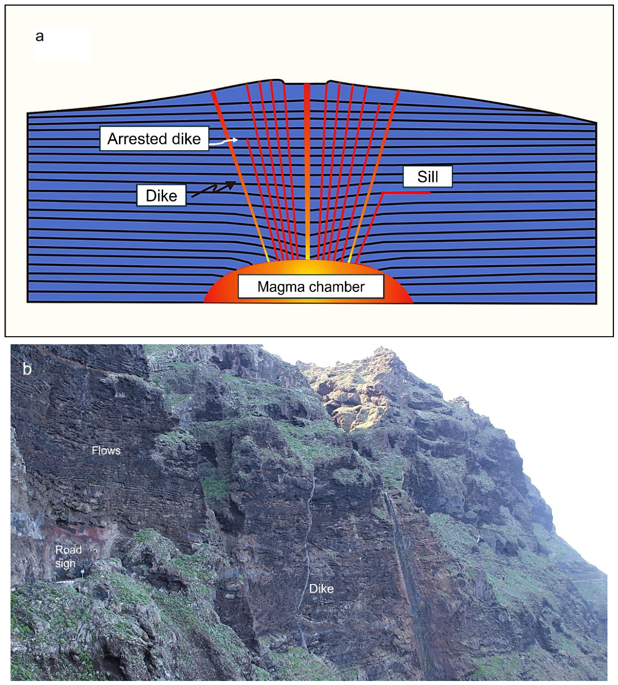
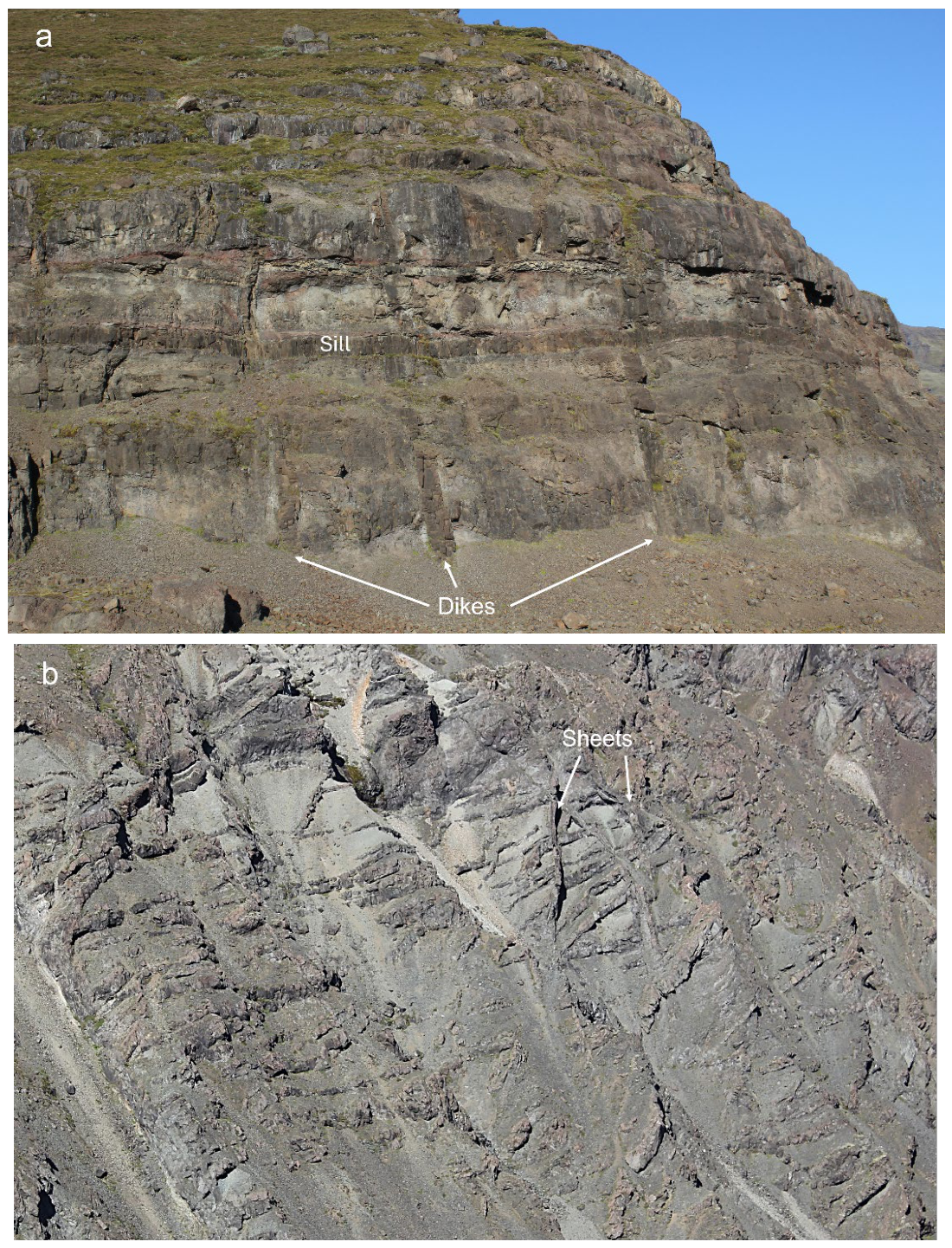
Shield volcanoes are almost entirely composed of basaltic rocks, lava flows, intrusions, and scoria layers in-between the lava flows (
Figure 1), while some also contain sedimentary interbeds. The intrusions are mainly dikes (
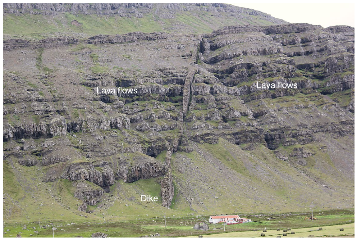
Figure 1 and
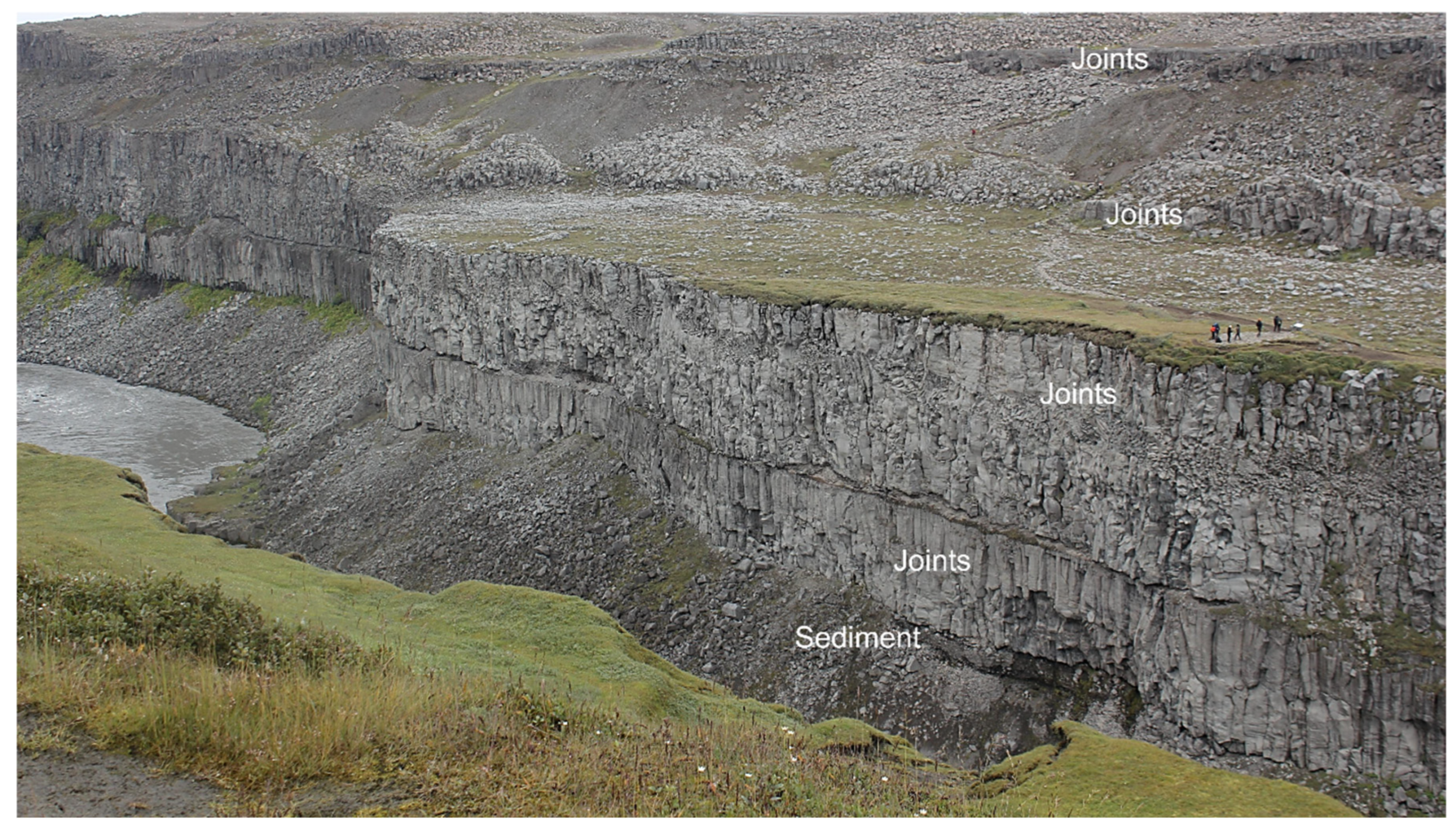
Figure 2), mostly dipping close to vertical, but also sills (normally parallel with layering and subhorizontal) and inclined sheets (cutting through layers and commonly dipping 30–60°). Additionally, sills tend to be thicker and with much better developed systems of columnar joints than inclined sheets. The lava flows and intrusions contain numerous columnar joints (
Figure 3). The joints not only lower their effective Young’s modules, that is, stiffness, but also decrease the tensile strength to as low as 0.5 MPa [
16,
17]. There are both horizontal and vertical joints in the sheet intrusions. The horizontal joints are best developed in dikes and the vertical joints in sills. Dikes, however, are generally much more common than sills in shield volcanoes (
Figure 1 and
Figure 2). Additionally, there are mechanically weak contacts between many lava flows (
Figure 1 and
Figure 3). So there are numerous horizontal weaknesses that propagating fractures can use while making their paths inside a shield volcano.
While there are numerous horizontal weaknesses, it follows from the main units that constitute a shield volcano being close to horizontal that vertical weaknesses are normally much more common. This is because vertical cooling joints are so common in the lava flows themselves (
Figure 3). Horizontal weaknesses are important for sill emplacement and for the parts of some lateral collapses, but these weaknesses are primarily contacts between layers rather than cooling joints. Vertical weaknesses, however, are important for all other fractures that have the potential of causing major volcano failure. These include dike-fed eruptions, general faulting, vertical collapses, and lateral collapses.
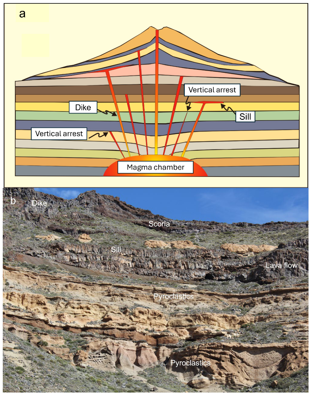
While a shield volcano is mostly made up of basaltic units, primarily lava flows and scoria layers in-between the flows, a stratovolcano is composed of rocks of widely different origin and composition (
Figure 4). One main difference between shield volcanoes and stratovolcanoes is the normally high proportion of pyroclastic material in the latter. More specifically, pyroclastic units can constitute as much as 50% of the volume of a stratovolcano. The compositional range is also much greater in stratovolcanoes than in shield volcanoes. Thus, while shield volcanoes are almost entirely basaltic, the rocks that constitute stratovolcanoes, not only the pyroclastic units but also lava flows and intrusions, range in composition from mafic to felsic.
In addition to igneous rocks, units of sedimentary rocks are common in stratovolcanoes. The sediments mostly come from sources higher up on the slopes of the volcano. Later, the sediments become buried by subsequent lava flows and pyroclastic flows, harden into rocks, and form a part of the internal solid structure of the volcano. Yet, many sedimentary units remain comparatively compliant (with a low Young’s modulus) as do many non-welded pyroclastic layers. By contrast, some welded pyroclastic layers may be stiffer (with a higher Young’s modulus) than common lava flows [
16,
17]. As we shall discuss further below, because a typical stratovolcano is composed of layers and contacts whose mechanical properties vary much more than those of a typical shield volcano, a stratovolcano is, as regards its greater resistance to the propagation of tectonic fractures, stronger than a shield volcano.
Both shield volcanoes and stratovolcanoes contain layers or units that have been subject to geothermal alteration. Because of the greater variation in composition of the layers that constitute a stratovolcano, geothermally altered layers are more common in stratovolcanoes than in shield volcanoes. Such layers can act as weak interfaces and, depending on their dips and other factors, may contribute to the development of landslides (lateral collapses). Alternatively, because compliant (soft) layers contribute to the material toughness of the parts of the volcano within which they are located, they may also play a role in tectonic fracture arrest. Under certain conditions, geothermally altered layers may thus encourage volcano failure, particularly for shallow-dipping parts of landslides. Under other conditions, they may encourage fracture arrest, particularly for propagating dikes, and thereby increase volcano strength.
Dikes, sills, and inclined sheets form a framework that reinforces or strengthens the volcanic structure, the edifice, as a whole [
17]. In many fossil and deeply eroded volcanoes, and also in some caldera walls, there are exposed networks of sheet intrusions (
Figure 5) that increase the overall stiffness and strength of a volcanic edifice, primarily in two ways. First, the framework of intrusions provides resistance against loading on the volcanic structure, whether external (such as due to nearby fault slip and earthquakes) or internal (such as during magma chamber inflation or deflation). While the main framework is normally composed of sheet-like intrusions, volcanic plugs (necks) may also add to the overall mechanical strength of the volcano. Necks are known to be commonly stronger—more resistant to erosion—than the rest of the volcano [
17]. Second, depending on its exact internal structure (the strongest being a combination of vertical dikes, inclined sheets, and horizontal sills), the framework tends to arrest or deflect the propagation of subsequently formed fractures (dikes, faults). This is partly because the sheet intrusions are normally stiffer (with a higher Young’s modulus) than the host rock, so a propagating fracture that meets any of them has a tendency to be deflected along the contact or arrested altogether—as explained in detail below.
While there are no detailed statistical studies as to the comparative frequency of dikes, sills, sheets, and associated networks in shield volcanoes and stratovolcanoes, sills are likely to be more common in the latter. This follows because, as explained above, the variety in mechanical properties—particularly Young’s modulus—is much greater in stratovolcanoes than in shield volcanoes. Consequently, the tendency for dikes and inclined sheets to deflect into sills, based on the mechanisms of Cook–Gordon delamination, elastic mismatch, and stress barriers [
17], is stronger in stratovolcanoes than in shield volcanoes. These considerations suggest that a stratovolcano would normally have a stronger sheet-intrusion network, and thereby, in that sense also, be mechanically stronger, than shield volcanoes.
4. Volcano Failure
Volcano failure here means a large-scale rupture of a part of the volcano. The fractures responsible for the rupture are primarily magma-driven extension fractures or faults. The magma-driven fractures are, as discussed above, mainly sills, inclined sheets, and dikes. While sills do not normally rupture many layers, since they are mostly confined to contacts between layers (
Figure 4 and
Figure 5), some sills propagate from one contact to another, referred to as transgressive sills. Sills can contribute to large-scale failure of a volcanic edifice through acting (while liquid or semi-liquid) as a lubricating, or at least a mechanically weak, layer that may encourage large-scale lateral collapses.
In forming their paths, dikes and inclined sheets, however, normally cut through numerous layers. So in this paper, reference to volcano failure through a magma-driven fracture means failure through the propagation of dikes and inclined sheets. While many stratovolcanoes have central conduits, these are normally not continuously open. Those that are open cavities are so usually over geologically short periods and reach only shallow depths. Most conduits are filled with rocks of various types, as is seen when the volcano becomes extinct and eroded and the fossil conduits are exposed as plugs (necks) of breccias and (mainly dike and inclined sheet) intrusions. Eruptions from conduits are presumably commonly the result of a single dike propagating through the conduit rocks to erupt at the surface rather than the conduit as a whole erupting.
This description of the function of conduits is supported by the results of drilling into the conduit of the Unzen Volcano in Japan [
18]. At the depth of 1.3 km below the summit of the volcano, the 500 m thick conduit is mainly composed of volcanic breccias within which there are emplaced numerous dikes and igneous (pyroclastic) veins. The dikes are subparallel (form a swarm), mostly close to vertical, and are oriented perpendicular to the local minimum principal compressive stress, σ
3. The dikes occur across the entire 500 m wide conduit, some are multiple, and range in thickness from 7 to 40 m. These results suggest that the means of magma transport in large elliptical or circular (in horizontal section, plan view) conduits may be primarily through dikes.
The most common type of large-scale volcano failure is through dike propagation, and particularly dike-fed eruptions. In the latter case, the failure of the volcano is more significant than in the case of an arrested (non-erupting) dike because the feeder dike propagates from its source to the surface. This means that the dike is a through fracture, extending from one free surface (the magma source) to another free surface (the Earth’s surface), and thereby cutting through all the layers and contacts between the source and the surface.
How common are large-scale volcano failures? Small fault displacements and small landslides are common, but large lateral collapses are comparatively rare. The same applies to large vertical collapses—caldera collapses; in any given volcano, whether a shield volcano or a stratovolcano, they occur much less frequently than volcanic eruptions. Since most volcanic eruptions are supplied with magma through dikes and inclined sheets, dike/inclined sheet propagation is the most common type of large-scale volcano failure. This is particularly so because not all dike/sheet injections reach the surface to feed eruptions—many become arrested at various depths in the volcano.
Some volcanoes erupt daily, others once every 0.1–10 years. Such high eruption frequencies, however, are commonly related to open central conduits, a rare feature, or lava lakes, rather than to feeder dike formation and associated edifice failure. In some shield volcanoes, such as Kilauea in Hawaii, there are periods of almost continuous eruptions followed by somewhat less frequent eruptions. For example, there was an almost continuous eruption activity in Kilauea for 35 years, from 1983 to 2018, when a major caldera collapse occurred. Following that collapse, there have been at least eight eruptions in Kilauea, mainly in the summit, but not a continuous eruption [
19]. The 35-year continuous eruption was facilitated by the formation of a multiple dike which allowed an easy path for the magma from the shallow chamber to the surface [
20,
21]. Among stratovolcanoes that erupt very frequently is Sakurajima in Japan, which often erupts many times each day, and Stromboli in Italy, which also erupts many times per day. These are exceptionally high frequencies and presumably related to a more or less open central conduit. A common eruption frequency in a mature stratovolcano, however, is once every several hundred to several thousand years [
7,
8,
9,
10]. Thus, for most polygenetic volcanoes, large-scale failure through dike/sheet propagation can have a frequency somewhere between once every few years to once every thousand years. For large-scale faulting, however, the frequency may be even lower.
5. Lateral and Vertical Collapses
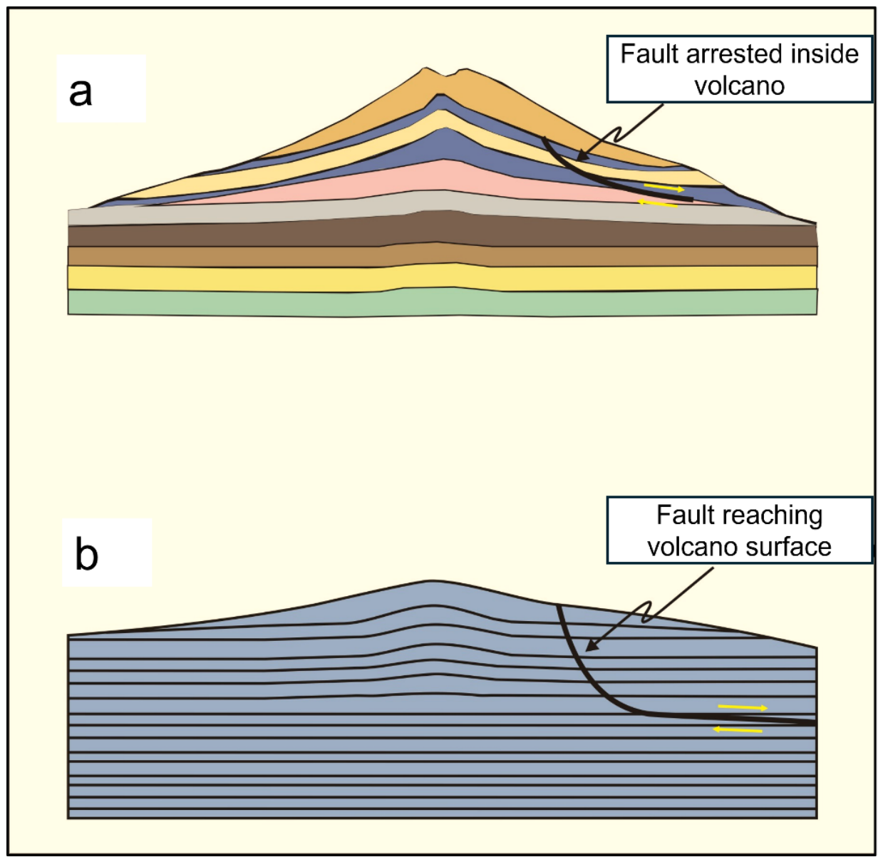
As in all tectonically active areas, faulting is common in polygenetic volcanoes, particularly during unrest periods. For example, when significant inflation and/or deflation takes place, small fault slips and associated earthquakes are common. Small fault slips, however, do not constitute large-scale volcano failure. But large fault slips do, and as regards volcano failures, these are the two main types: lateral collapses and vertical collapses.
Lateral collapses are common in shield volcanoes (
Figure 6 [
22]). Detailed studies have been made as to the frequency of lateral collapses on the Canary Islands [
23,
24,
25,
26]—some parts of which have the structure of shield volcanoes—on Reunion Island [
27], and on the Big Island of Hawaii [
28,
29,
30]. Large lateral collapses are very common, and especially well documented on Big Island, many occurring as large submarine landslides. Although many landslides associated with shield volcanoes are submarine, they are also very common on land [
31,
32].
Lateral collapses occur also in stratovolcanoes [
33,
34] but very small landslides are more common [
14,
35]. That small landslides occur in stratovolcanoes is a direct consequence of their steep slopes, so they are most frequent in the upper parts of the volcanoes. However, large lateral collapses are less frequent in stratovolcanoes than might be expected given the steepness of their slopes [
14]. There are indications that for a large lateral collapse to occur in a stratovolcano, some specific mechanical or tectonic conditions need to be satisfied. The conditions identified as encouraging large lateral collapses in stratovolcanoes include mechanically weak and outward-dipping layers, parts of which may be hydrothermally altered into clay and other soft and low-strength materials, as discussed above. Included here, although not clearly identified so far, is sill emplacement along outward-dipping contacts. Other tectonic events that provide conditions for lateral collapses in stratovolcanoes are shallow dike injections [
15,
36] and earthquakes [
37,
38].
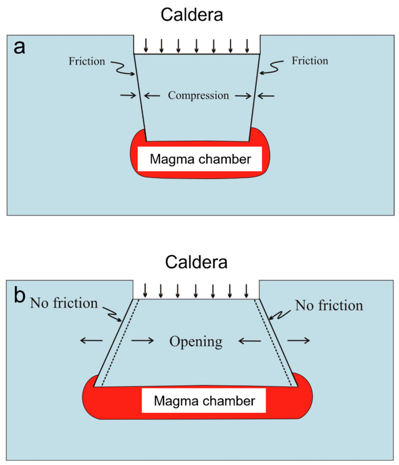
Vertical collapses, that is, caldera collapses, happen at some time in many polygenetic volcanoes. The collapses occur on ring fault that are of two main geometric types: outward dipping and inward dipping (
Figure 7). The inward-dipping ring faults appear to be more common. Since they are subject to greater friction along the ring fault, their displacements tend to be smaller than those on outward-dipping ring faults. The latter is less frequent but more dangerous as regards the eruption potential. This follows because during an outward-dipping ring fault, displacement there is almost always a ring-dike forming, meaning that the friction along the fault walls is minimal (
Figure 7). Furthermore, since the fault dip is outward and the friction is minimal, there is basically no mechanism for stopping the subsidence of the caldera body—the ‘piston’—for subsiding deep into or, for a totally molten magma chamber, to the floor of the chamber. This means that much of the magma in the chamber may be squeezed out during an eruption associated with the subsidence of the caldera floor along an outward-dipping ring fault [
17].
While collapse calderas occur in both stratovolcanoes and shield volcanoes, the total number of calderas hosted by stratovolcanoes is greater than the number hosted by basaltic edifices [
39]. But these numbers are misleading in the sense that there are simply many more known and classified stratovolcanoes than shield volcanoes [
7,
8,
9,
10]. Thus, when the formation of and slip on existing ring faults of calderas is analysed, the results suggest that both are more common in individual shield volcanoes [
40] than in individual stratovolcanoes [
41].
6. Fracture Propagation and Resistance
The most common large-scale failure of polygenetic volcanoes is through inclined sheet and dike propagation (
Figure 1,
Figure 2 and
Figure 4). Since both are sheet intrusions and propagate as magma-driven extension fractures, the basic principles of their propagation, hence for the resulting volcano failure, will be discussed together here. Thus, unless specified otherwise, in this section, the word dike covers both subvertical intrusions, ordinary dikes, as well as inclined sheets. The conditions for faulting—ordinary faulting as well as the initiation and development of ring faults—is mechanically different from that of the initiation and development of dikes, primarily because the former are shear fractures while the latter are extension fractures. The resistance to large-scale volcano failure, however, is basically the same for both shear and extension fractures. Thus, here we analyse the general aspects of large-scale volcano failure through the analysis of the conditions for, and rock resistance to, dike fracture propagation.
6.1. Fracture Initiation
For a fluid-driven fracture such as a dike, the condition for source rupture and fracture initiation is given by [
17]:
Here,
denotes the lithostatic stress at the location of rupture and dike initiation at the boundary (usually the roof) of the source,
the excess magma pressure in the source,
σ3 the minimum compressive (maximum tensile) principal stress, and
the local in situ tensile strength at the rupture site. Here, compressive stress is regarded as positive (tensile stress as negative), and excess magma pressure with reference to lithostatic stress (in excess of the lithostatic stress). A lithostatic state of stress means that the stress magnitude increases with depth in the earth’s crust or lithosphere at a rate which depends on the density of the crustal/lithosphere layers, and that all the principal stresses are equal. It follows that lithostatic stress is an isotropic (a hydrostatic or spherical) state of stress.
When there is no unrest in a polygenetic volcano, its magma source can neither be expanding nor contracting. This implies that the source is in a mechanical or lithostatic equilibrium with the host rock before unrest and dike injection [
17]. It then follows that there is no excess pressure in the source, so that
pe = 0, and the pressure in the source exactly balances the crustal stresses at the boundary of the source. Then the state of stress at the boundary of the source is:
. Equation (1) may also be written as
, where
pt is the total fluid pressure in the source at the time of rupture and dike injection, as can be derived directly from Griffith’s theory of fracture [
42].
6.2. Magma Overpressure
A magma-driven fracture, a dike, propagating vertically from its source, is not only driven by the excess pressure at its point of initiation, but also by the difference in density between the magma and the host-rock layers through which the dike propagates. The density difference gives rise to a buoyancy term which contributes to the magma pressure driving the dike propagation, which is referred to as driving pressure or overpressure
po, and given by:
Here,
denotes the excess magma pressure in the source,
ρr the average host-rock density,
ρm the average magma density,
g is the acceleration due to gravity,
h the dip dimension of the dike, and
σd is the differential stress (the difference between the maximum and the minimum principal stress) in the host rock at the depth in the crust where the dike overpressure is estimated. For a propagating (fluid) dike, that depth is determined by associated earthquakes [
43] and, if the dike upper tip (top) is shallow, through dike-induced deformation at the surface [
44]. For a solid dike in a fossil (extinct) volcano or volcanic system, this depth refers to the depth of the dike exposure below the original top of the volcano/volcanic system within which the dike was emplaced.
The buoyancy term can be positive (when the average fluid density is less than average rock density up to the point of overpressure measurement along the dike), zero or neutral (when the average rock and fluid density are the same), or negative (when the average rock density is less than average fluid density). The buoyancy term, however, does not provide a significant contribution to the overpressure until the dip-dimension or height of the dike above its point of origin in the roof of the source has reached about 1000 m or more.
When the magma in the dike is acid or intermediate, the buoyancy is normally positive. This applies particularly to acid magmas whose typical densities are 2180–2250 kg m
−3, whereas the densities of shallow crustal layers in volcanic areas are 2300–2500 kg m
−3 [
17]. In the uppermost 1–2 km of the crust, however, the buoyancy term may be close to zero or possibly somewhat negative for intermediate magmas because typical densities of intermediate magmas such as andesite are 2450–2500 kg m
−3. Mafic magmas, however, have common densities of 2650–2800 kg m
−3 and so for such magmas the buoyancy term is normally negative in the uppermost 1–2 km of the crust. At deeper crustal levels the buoyancy term for mafic magmas is first zero and then, as the depth increases, positive.
Once a dike has initiated and started to propagate upwards, the conditions for its further propagation, or possible arrest [
45,
46], can also be formulated in terms of fracture mechanics principles, namely as follows:
Here, for the host rock,
KIc is the fracture toughness for an extension (mode I) fracture (the mode appropriate for dikes),
a is the dip dimension (height) of the dike,
GIc is the material toughness (for mode I),
E is Young’s modulus (stiffness), and
ν is Poisson’s ratio. Equation (3) is for plane-stress conditions (applicable for crustal segments that are laterally very extensive in comparison with their thickness), whereas Equation (4) is for plane-strain conditions (where the lateral dimensions of the crustal segment under consideration are similar to that of its thickness), in which case the term
) is included. When a dike is many times longer (strike dimension) than its height (depth to its source), then Equation (3) is applicable, but when these dimensions are similar or the dike is shorter than its height, Equation (4) is applicable. Equations (3) and (4) were initially derived for homogeneous and isotropic materials. They can be applied to heterogeneous and anisotropic materials, but cannot be used to forecast accurately the (commonly complex) propagation paths of dikes, particularly in stratovolcanoes. These paths are complex primarily because of the effects of layering in the crust and in the volcanoes themselves, to which we turn now.
6.3. Theory of Fracture-Path Selection
There are various factors that affect the propagation paths of dikes, and many of these are discussed below. Here, the focus is on the general principles that control path selection of dikes. These principles apply to all extension fractures—and with modifications (taking into account that shear stresses rather than normal stresses control shear-fracture propagation) of faults as well. These principles have been discussed in detail in recent papers [
6,
45], so the summary below will be reasonably brief.
The principal idea is that path selection by dikes is controlled by Hamilton’s principle of least action. This implies that the dike selects the path along which the time integral of the difference between the kinetic energy and the potential energy is an extremum (a maximum or a minimum) relative to all other possible paths that have the same rupture sites at the source and the same end points inside the crust (or, for a feeder, at the surface). Most commonly, however, the extremum is actually a minimum.
Dikes typically propagate at rates between 0.01 m s
−1 and 1 m s
−1 [
6]. For comparison, earthquake ruptures propagate at rates similar to those of S-waves—so commonly at rates of 2–4 km s
−1 in the upper parts of the crust. Thus, the kinetic energy is mainly associated with seismic waves of the earthquakes induced during dike propagation whereas the potential energy is the strain energy stored in the volcano/volcanic system plus the elastic energy supplied by the forces acting on the volcano/volcanic system during dike propagation. When the kinetic energy is omitted and some additional mechanical conditions are satisfied, Hamilton’s principle of least action reduces to the principle of minimum potential energy—as discussed below.
For a discrete and conservative system, Hamilton’s principle may be given as:
where
S denotes the action,
L the Lagrangian,
t1 and
t2 two arbitrary chosen times in the course of the development of the system,
δ the variational symbol (indicating a small change),
T the kinetic energy, and
V the potential energy. It follows that the Lagrangian
L is equal to the difference between the kinetic energy and the potential energy:
The action integral (Equation (5)) means that when a system moves from time t1 to time t2, the chosen path makes the variation of the action, δS, zero, that is, the one for which the action integral is an extremum (assumed a minimum) along the selected path. Action has the dimensions of energy × time (or linear momentum × distance) and the unit of J s. Of the infinite number of possible dike paths from the rupture site at its source to the place of arrest, or to the surface (if a feeder dike), the selected one is where the energy transformed multiplied by the duration of the propagation is a minimum.
Equation (5) is for a discrete system—one that is composed of numerous distinct particles—while a volcano/volcanic system behaves mechanically as a continuous (approximately elastic) system. A discrete system composed of N independent particles and without constraints (free particles) has 3N degrees of freedom—the latter meaning the number of independent coordinates needed to specify the configuration of the system that is compatible with any prescribed constraints. This is because for each particle in a three-dimensional space three independent coordinates (such as x, y, z) are needed to specify the particle’s position; thus, for N independent particles, we need 3N coordinates, that is, degrees of freedom. Here, the position at a given moment of the N particles (for a discrete system) or material points (for a continuous system) is referred to as the system configuration. In a discrete system N is always finite (while often very large), but in a continuous system N is infinite—and so are the degrees of freedom.
For a continuous system such as a volcano/volcanic system, the potential energy
V (Equation (6)) does not depend only on the external forces, such as plate-tectonic forces, acting on the system, but also on the internal strain energy
U. The strain energy is due to internal forces stored in the elastic host rock of the magma source before it ruptures and a dike/sheet is initiated. During source inflation the strain energy concentrates in the volcano/volcanic system hosting the source. If the generalised external forces
Qi are conservative, they are derivable from the potential energy
V, thus:
Here,
qi denotes generalised coordinates. We can then define the Hamilton’s principle of least action for a volcano/volcanic system modelled as an elastic solid as follows [
47,
48,
49]:
where all the symbols have been defined above. In this formulation, there are no constraints and the external forces acting on the volcanic system do not depend on the resulting elastic displacements; that is, the forces are conservative, as is commonly assumed for an elastic deformation [
47,
50].
The energy associated with the generalised external force acting on the volcanic system (Equation (7)) together with the strain energy stored in the volcanic system/volcano hosting the magma chamber constitutes the total potential energy Π:
so that the Lagrangian (Equation (6)) becomes:
It follows that Hamilton’s principle for a volcanic system (Equation (8)) may be written as:
The kinetic energy transformed during typical dike propagation is comparatively small. This is because of the slow rate of propagation of dikes (mostly 0.01–1 m s
−1). Consider the case where the transformed kinetic energy is assumed zero, so that
T = 0, and furthermore that the volcanic system under consideration behaves as a conservative, elastic system. Then it follows [
47,
49,
51] that the total potential energy of the system in equilibrium is a minimum, and therefore:
which is a presentation of the mechanical principle of minimum potential energy. Thus, under the conditions discussed above, Hamilton’s principle of least energy reduces to the principle of minimum potential energy or least work. In essence, this principle means that the actual displacements or configurations of an elastic body under external and internal loading are those that minimise the total potential energy of the body. Thus, for an elastic body to be in a stable equilibrium, the total potential energy of the body must be a minimum.
Using the principle of least action or minimum potential energy, we can theoretically forecast the likely propagation paths of dikes, and thereby the most common type of large-scale failure of volcanic edifices. For any specific volcano, however, the general mechanical layering and large-scale fracturing needs to be known along the estimated (from Hamilton’s principle) potential paths in order to forecast the actual dike path with reasonable accuracy.
6.4. Rock Resistance to Fracture
We have now explained how, in principle, a tectonic fracture-propagation path is selected based on the principles of Hamilton and minimum potential energy. But the rocks that constitute a polygenetic volcano offer a resistance to fracture propagation. This resistance means that an initiated rock fracture may propagate for only a short distance until it becomes permanently arrested. Alternatively, the resistance may result in the fracture path being more irregular and longer—and thus requiring greater energy for its formation—than would be the case if the volcano was composed of a single rock unit with uniform mechanical properties. One main mechanical difference between stratovolcanoes and shield volcanoes is in their resistance to fracture propagation.
The principal measure of resistance to fracture propagation, and failure in general, in solid materials is toughness. Toughness is a measure of the energy needed for the material to fracture. Thus, for tough rock, much energy is absorbed before it fails—here, as a tectonic fracture initiates and propagates through the rock. In volcanoes and volcanic systems, one major reason for high toughness is layering; more specifically, the different mechanical properties of the layers that constitute the volcano as well as the contacts between the layers (
Figure 1,
Figure 2,
Figure 3,
Figure 4 and
Figure 5). Toughness of polygenetic volcanoes and volcanic systems—and layered rocks in general—is discussed in detail elsewhere [
17]. The following is a summary of the main conclusions that are relevant to the present discussion of the mechanical strength (fracture resistance) of shield volcanoes and stratovolcanoes.
Toughness in layered rocks is primarily related to the tendency to fracture deflection or arrest at (or close to) contacts between layers or units. For an upward propagating fracture, this tendency is attributable to three main factors. These are, first, the relationship between the fracture-parallel tensile stresses ahead of the propagating fracture and the tensile strength of the contact versus that of the adjacent rock layers. If the tensile stress is greater than the tensile strength of the contact, the contact may open up, resulting in either fracture deflection or arrest. Second, rotation of the local principal stresses at the contact between the layer or unit hosting the fracture at a given moment during its propagation and the layer/unit above the contact. More specifically, this rotation results in the local stresses in the layer above the contact becoming unfavourable to the further upward propagation of the fracture, resulting in fracture deflection or arrest. Third, unfavourable (for further fracture propagation) material toughness of the contact in comparison with the material toughness of the adjacent rock. Again, this may result in deflection of the fracture into the contact or fracture arrest.
The first factor is referred to in solid mechanics as Cook–Gordon delamination or debonding. Its main effect is the opening of a contact that is comparatively weak in fracture-parallel tension. Thus, the tensile stresses ahead of a dike tip may open the contact, resulting in the fracture propagation stopping altogether or becoming deflected into the contact—which, for a dike, may result in sill formation [
17,
45,
46]. In volcanoes and volcanic systems, opening of contacts between rock layers or units is most likely to happen at shallow crustal depths.
The second factor is common at contacts between mechanically dissimilar rocks and can occur at any depth in the crust. Here the principal stresses rotate so that the local stress in a layer or unit above the one hosting a propagating fracture at a given moment becomes unfavourable to the further upward propagation of that type of fracture. The layer or unit with unfavourable local stress is referred to as a stress barrier. A vertically propagating fracture would then either stop its propagation on reaching the contact—or just before meeting the contact [
5,
52]—or, alternatively, deflect into the contact. For a fluid-driven extension fracture such as a dike, a stress barrier would have σ
1 horizontal and σ
3 vertical, and the deflected part along the contact would form a sill [
46].
The third factor pertains to a mixed-mode fracture, namely a fracture that propagates partly in one mode and partly in another, the principal modes being I, II, and III. Such a propagation makes a fracture path from one site to another inside the crust—for a dike from the rupture site at its source to its place of arrest, or to the surface (if a feeder dike)—comparatively long and, therefore, requires an extra energy input for the fracture propagation. This factor is referred to as elastic mismatch.
Consider first the total energy release rate G
total for a mixed-mode (extension and shear) loading, which may be given as [
53]:
The notation is as follows: G is the energy-release rate, ν is Poisson’s ratio, E is Young’s modulus, and K is the stress-intensity factor. The critical value of G, in joule per square metre (J m
−2), is named material toughness, whereas the critical value of K, given as stress times the square root of (crack) length (MPa m
1/2), is named fracture toughness. Equation (13) assumes plane-strain conditions, so that the dimensions of the fractured rock body, the crustal segment, are all of a similar size. Here, the subscripts I–III for G and K denote the crack loading modes, that is, the movement of the crack walls [
17]. Extension fractures such as dikes are modelled as mode I cracks whereas faults and other shear fractures are modelled as a mode II and III cracks. In particular, many normal and reverse (dip–slip) faults are modelled as mode II cracks whereas many strike–slip faults are modelled as mode III cracks.
For a pure extension fracture (
Figure 1,
Figure 2,
Figure 4 and
Figure 5), modelled as a mode I crack, the first term on the right-hand side of the second equals sign in Equation (13) gives the total energy release rate, G
I. However, deflection of such a fracture into the contact between two layers or units would normally entail a mixed crack mode, that is, two or more modes [
54,
55]. Then the total energy release rate is no longer G
I but rather is a combination of, for example, G
I and G
II or G
III or all three. It follows for a given length of fracture propagation, the energy required to deflect an extension fracture from, say, its vertical path into and along, say, a horizontal contact between layers or units needs more energy than the entire propagation as an extension fracture in pure mode I.
A further energy input is required for a fracture deflected into contacts along parts of its path because the path is then longer—with a zig-zag geometry—than in the case of a comparatively straight vertical path between given fracture endpoints (such as the source of a feeder dike and the surface). This is because the stress-intensity factor in Equation (13) varies positively with the length of the fracture path, namely (for mode I crack) as:
Here,
KI is the mode I stress-intensity factor,
po is the magmatic overpressure driving the dike, and a is half its dip dimension (half its vertical path length). A measure of the general tendency for a propagating, say vertical extension fracture, to become deflected into a contact between layers or units is the Dundurs elastic extensional mismatch parameter α
D is given by [
54,
55]:
Here, E
2 is the plane-strain extensional Young’s modulus of the layer or unit hosting the vertically propagating fracture and E
1 is Young’s modulus of the layer or unit above the contact. The fracture would tend to deflect into a contact that it meets along its path if E
1 > E
2. As the numerator E
1 − E
2 increases, that is, the positive difference between these Young’s moduli becomes greater and the Dundurs mismatch parameter α
D increases, the tendency for the fracture to deflect into the contact increases [
54,
55,
56,
57].
The third factor favours arrest or deflection of a vertically propagating fracture into a horizontal where the layer above the contact has a higher Young’s modulus than the layer below the contact (and hosting the propagating fracture). The other two factors that favour fracture arrest/deflection are not so restricted; they both allow for the layer below the contact having a higher Young’s modulus than the layer above the contact. A contact between layers can open up (resulting in delamination) when a propagating fracture approaches it (from below) if it is mechanically weak enough in relation to the fracture-parallel tensile stress at and ahead of the fracture tip, irrespective of whether the layer above or below the contact is the one with the higher Young’s modulus. Similarly, unfavourable local stresses for fracture propagation, stress barriers, may form in a comparatively low-Young’s modulus layer on top of a layer with a higher Young’s modulus.
The main point as regards tectonic fracture deflection or arrest at or close to contacts is the contrast in mechanical properties of the layers or units across the contact; the greater the contrast, the more likely is the fracture to become deflected or arrested on meeting the contact. Deflection along contacts and arrest become less and less likely as the properties of the rock layers on either side of a contact become more similar. It follows that on meeting contacts between layers, propagating tectonic fractures are more likely to be deflected or arrested in stratovolcanoes than in shield volcanoes. This means that fracture resistance is greater in stratovolcanoes, so that they are mechanically stronger than shield volcanoes.
No systematic, accurate studies have been made on the long-term fraction of dikes that reach the surface to erupt in shield volcanoes—a research topic of great importance given its impact on hazard assessment. For shorter periods in basaltic volcanoes and volcanic systems, however, many and sometimes most of the injected dikes reach the surface. This is well known from volcanoes such as Kilauea in Hawaii and the dike-fed eruptions in the past five years on the Reykjanes Peninsula in Iceland. Many of these dike-fed eruptions, however, are through multiple dikes, which offer especially favourable conditions for injected dikes reaching the surface [
6]. As for stratovolcanoes, some detailed studies have been made on the long-term fraction of injected dikes becoming arrested (and thus ending as non-feeders). Thus, 93% of 165 dike studied in the uppermost 200 m of the caldera walls of Miyakejima in Japan turned out to be arrested [
58]. Since the caldera collapse in the year 2000, the dikes are particularly well exposed in the caldera walls, making it possible to determine their propagation paths with great accuracy. The remarkable thing is that even at a shallow depth of less than 200 m below the surface, the great majority of the dikes are seen to end vertically, that is, to become arrested, primarily at contacts between mechanically dissimilar rocks, mostly lava flows with a high Young’s modulus and more compliant tuff layers. Thus, these observations, while so far being less extensive than they should be, are in agreement with tectonic fractures—here dikes—being more easily arrested or deflected at contacts in stratovolcanoes than in shield volcanoes, meaning that stratovolcanoes are mechanically stronger than shield volcanoes.
7. Volcano Failure Through Dike Propagation
According to Hamilton’s principle, dikes select the path that minimises the action (Equation (11)) which, because of the slow propagation of most dikes, reduces to the path of minimum potential energy (Equation (12)). In order for a dike to propagate, the magmatic pressure must be high enough to rupture the rock and open up the fracture. When the magma in the dike solidifies, there is shrinkage, so that the thickness of the dike is about 90% of the opening of the magma-driven fracture and thus a good measure of the opening while the dike is propagating [
17]. Additional indications of dike fracture opening, even if generally less accurate than direct field measurements of solidified dikes, are geodetic measurements based on detected surface displacements [
3,
23,
59]. These are generally most accurate for feeder dikes [
59].
For a propagating dike, the magmatic overpressure (Equation (2)) must repeatedly rupture the rock at and ahead of the dike tip at a given time and location and then push the walls aside to form the dike fracture. The horizontal displacement of the walls—the opening of the dike fracture—requires work, that is, energy. Because stress is force per unit area, it follows that more energy is needed to displace (open up) the fracture walls against a large than a small compressive force per unit area (stress) acting against the opening displacement. If the force acting perpendicular to the dike fracture being opened is tensile, as may happen at a shallow depth in rift zones, then that tensile force adds to, rather than acting against, the opening-displacement force, thereby making the opening easier, that is, requiring less energy. The principal stresses are defined so that σ1 is the maximum principal compressive stress (maximum compressive force per unit area), σ2 is the intermediate principal compressive stress, and σ3 is the minimum principal compressive stress (and sometimes, in fact, a tensile stress), so that .
From the definition of the principal stresses and Hamilton’s principle of least action (or its reduced form, the principle of minimum potential energy), it follows that a dike fracture should ideally select a path that is everywhere perpendicular to the orientation of σ3. The only paths that satisfy that condition are the ones which include σ1 and σ2. In two-dimensional plots, the paths therefore coincide with the trajectories (directions) of σ1, so that these can be used to forecast the likely propagation paths of dike fractures. Furthermore, the time constraints in Hamilton’s principle imply that a dike fracture tends to follow the shortest path that is compatible with the other constraints. We will now apply the principles established above to dike propagation to the surface of a shield volcano.
7.1. Dike Propagation in a Shield Volcano
While shield volcanoes are clearly layered (
Figure 1), essentially all the layers are basaltic and mostly of similar mechanical properties. There are some scoria layers, which would normally be more compliant than the central parts of the pahoehoe flow units and aa lava flows, and there may be occasional sedimentary layers, but overall the shield volcanoes show comparatively small variation in mechanical properties—particularly when compared with the variation in mechanical properties of the layers that constitute stratovolcanoes. To a first approximation, we may therefore model shield volcanoes as having close to uniform mechanical properties, that is, being composed of layers whose properties vary very little up through a potential dike path.
For a shield volcano, the main change in Young’s modulus is related to the depth of the layers. The basaltic layers at and close to the surface would normally be more compliant than layers of the same composition that are buried at depth in the volcano. This follows for two main reasons. First, there is a slight compaction of the layers with increasing depth of burial, particularly of the porous parts (scoria parts) at the top and bottom of many of the aa layers and, to a lesser degree, of the flow units of pahoehoe lava flows. This compaction is due to the weight or overburden pressure which increases with depth. Second, the pores in the scoria parts as well as vesicles and cooling joints and contacts between layers tend to become gradually filled with secondary minerals such as quartz, zeolites, or calcite (depending on temperature and depth). Both the compaction and the mineral infill result in increasing density and stiffness (Young’s modulus) of the layers with increasing depth of burial.
The following numerical models for shield volcanoes and stratovolcanoes are not applied to any specific volcano. They are rather meant to show how potential paths of dikes (and inclined sheets and sills) are affected by increasing mechanical contrast between the layers and units that constitute the volcano. Thus, the isotropic homogeneous models are at one end of the spectrum, and may be regarded as a idealisation of some shield volcanoes. At the other end of the spectrum are models where there is a considerable contrast in the mechanical properties of the layers and units that constitute the volcano. These may be regarded as representing many stratovolcanoes.
Consider first a shield volcano where the stiffness (Young’s modulus) of the layers is regarded as constant, namely 40 GPa (and Poisson’s ratio as 0.25). These values are appropriate average values for the uppermost 10 km of the crust in Iceland [
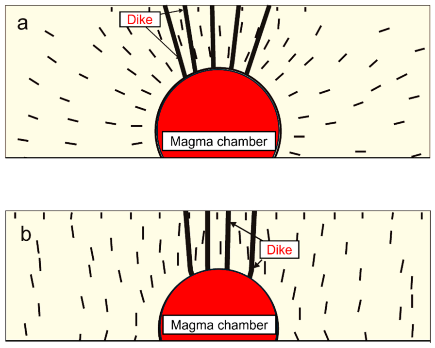
17]. The volcano is gently sloping, so we take the surface simply as flat. The lower part of the model is fastened, as indicated by crosses, so as to avoid any rigid-body rotation or translation. We regard the magma chamber as being with a circular vertical cross-section, but subject to two types of loading (
Figure 8a,b). In model a, the only loading is internal magmatic excess pressure of 5 MPa. In model b, the only loading is horizontal external tensile stress of 5 MPa. In both cases, the loading is close to a typical high in-situ tensile strength of rocks.
Figure 8.
Dike propagation paths, including those of feeder dikes, differ depending on the loading [
17]. Here the effects of different loading on likely dike paths are shown for dikes injected from a shallow magma chamber and hosted by a homogeneous, isotropic part of the crust whose Young’s modulus and Poisson’s ratio are 40 GPa and 0.25, respectably. In these numerical models the shallow magma chamber has a circular vertical cross-section, but only the upper part of the chamber is shown. The short straight lines, ticks, represent the direction of the maximum compressive principal stress, σ
1. The stress magnitudes (contours) around similar chambers are shown in
Figure 9 and
Figure 10. (
a) A magma chamber subject to internal excess magmatic pressure of 5 MPa as the only loading. Five potential paths for feeder dikes are indicated. Notice that while subvertical dikes (
Figure 1b,
Figure 2 and
Figure 5a) are favoured above the uppermost part of the chamber, inclined sheets would be favoured, based on the dips of the σ
1-trajectories, from the marginal parts of the chamber—both of which are commonly observed close to fossil magma chambers (
Figure 5b). (
b) A magma chamber subjected to external horizontal tension of 5 MPa as the only loading. Four potential paths for feeder dike propagation paths are indicated. All the indicated dike paths are vertical and the same would apply for sheet injections from the marginal parts of the chamber—they would also tend to result in subvertical dikes. Thus, edifice failure through the propagation of magma-filled fractures can result in different fracture paths depending on whether the main loading is internal pressure or external tension.
Figure 8.
Dike propagation paths, including those of feeder dikes, differ depending on the loading [
17]. Here the effects of different loading on likely dike paths are shown for dikes injected from a shallow magma chamber and hosted by a homogeneous, isotropic part of the crust whose Young’s modulus and Poisson’s ratio are 40 GPa and 0.25, respectably. In these numerical models the shallow magma chamber has a circular vertical cross-section, but only the upper part of the chamber is shown. The short straight lines, ticks, represent the direction of the maximum compressive principal stress, σ
1. The stress magnitudes (contours) around similar chambers are shown in
Figure 9 and
Figure 10. (
a) A magma chamber subject to internal excess magmatic pressure of 5 MPa as the only loading. Five potential paths for feeder dikes are indicated. Notice that while subvertical dikes (
Figure 1b,
Figure 2 and
Figure 5a) are favoured above the uppermost part of the chamber, inclined sheets would be favoured, based on the dips of the σ
1-trajectories, from the marginal parts of the chamber—both of which are commonly observed close to fossil magma chambers (
Figure 5b). (
b) A magma chamber subjected to external horizontal tension of 5 MPa as the only loading. Four potential paths for feeder dike propagation paths are indicated. All the indicated dike paths are vertical and the same would apply for sheet injections from the marginal parts of the chamber—they would also tend to result in subvertical dikes. Thus, edifice failure through the propagation of magma-filled fractures can result in different fracture paths depending on whether the main loading is internal pressure or external tension.

Figure 9.
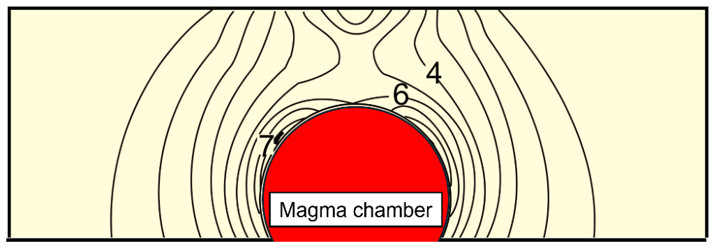
Stress concentration around the upper part of a shallow magma chamber, of a circular vertical cross-section (only the upper part is shown here) subject to internal excess pressure as the only loading. When a chamber subject to internal excess pressure as the only loading—here the pressure is 5 MPa—is located close to the surface relative to its size, as here, the highest tensile stress concentration (shown as contours of the maximum principal tensile stress, σ
3) is no longer around the top of the chamber roof (the point closest to the free surface), but rather around two locations at the upper margins of the chamber (where the stress is shown as 7 MPa at the left margin of the chamber). In combination with the results in
Figure 8a, this numerical model shows that failure of a volcanic edifice through the propagation of a magma-filled fracture from its shallow magma chamber, when the main loading is internal excess pressure, would commonly be through an inclined sheet (the location of the highest tensile stress concentration shown here) rather than a subvertical dike. The part of the crust hosting the chamber is with the same mechanical properties as in
Figure 8, namely homogeneous and isotropic with a Young’s modulus of 40 GPa and a Poisson’s ratio of 0.25.
Figure 9.
Stress concentration around the upper part of a shallow magma chamber, of a circular vertical cross-section (only the upper part is shown here) subject to internal excess pressure as the only loading. When a chamber subject to internal excess pressure as the only loading—here the pressure is 5 MPa—is located close to the surface relative to its size, as here, the highest tensile stress concentration (shown as contours of the maximum principal tensile stress, σ
3) is no longer around the top of the chamber roof (the point closest to the free surface), but rather around two locations at the upper margins of the chamber (where the stress is shown as 7 MPa at the left margin of the chamber). In combination with the results in
Figure 8a, this numerical model shows that failure of a volcanic edifice through the propagation of a magma-filled fracture from its shallow magma chamber, when the main loading is internal excess pressure, would commonly be through an inclined sheet (the location of the highest tensile stress concentration shown here) rather than a subvertical dike. The part of the crust hosting the chamber is with the same mechanical properties as in
Figure 8, namely homogeneous and isotropic with a Young’s modulus of 40 GPa and a Poisson’s ratio of 0.25.

Figure 10.
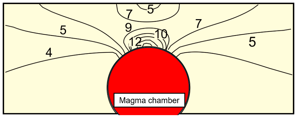
Stress concentration around the upper part of a shallow magma chamber, of a circular vertical cross-section (only the upper part is shown here) subject to external horizontal tensile stress as the only loading. When a chamber is subject to external horizontal tensile stress, which may occur in rift zones, as the only loading—here the tensile stress is 5 MPa—the highest tensile stress concentration (shown as contours of the maximum principal tensile stress, σ
3) occurs at the top of the chamber roof (the point closest to the free surface), namely the region where the tensile stress reaches 12 MPa. In combination with the results in
Figure 8b, this numerical model shows that failure of a volcanic edifice through the propagation of a magma-filled fracture from its shallow magma chamber, when the main loading is horizontal external tension, would commonly be through subvertical dikes [
17]. The crustal segment hosting the chamber has the same mechanical properties as in
Figure 8, namely homogeneous and isotropic with a Young’s modulus of 40 GPa and a Poisson’s ratio of 0.25.
Figure 10.
Stress concentration around the upper part of a shallow magma chamber, of a circular vertical cross-section (only the upper part is shown here) subject to external horizontal tensile stress as the only loading. When a chamber is subject to external horizontal tensile stress, which may occur in rift zones, as the only loading—here the tensile stress is 5 MPa—the highest tensile stress concentration (shown as contours of the maximum principal tensile stress, σ
3) occurs at the top of the chamber roof (the point closest to the free surface), namely the region where the tensile stress reaches 12 MPa. In combination with the results in
Figure 8b, this numerical model shows that failure of a volcanic edifice through the propagation of a magma-filled fracture from its shallow magma chamber, when the main loading is horizontal external tension, would commonly be through subvertical dikes [
17]. The crustal segment hosting the chamber has the same mechanical properties as in
Figure 8, namely homogeneous and isotropic with a Young’s modulus of 40 GPa and a Poisson’s ratio of 0.25.

Based on the direction of the trajectories (shown as short lines, ticks) of σ
1,
Figure 11 indicates five potential paths of feeder dikes for the model subject to internal excess pressure and four potential paths of feeder dikes for the model subject to external tension. The potential feeder dikes propagate through the entire lava pile above the magma chamber and therefore represent a through-going extension-fracture failure of the lava pile. The σ
1—trajectories are either subvertical or steeply inclined above the entire upper part of the magma chamber for the external tension loading (
Figure 8b), and for the central part above the magma chamber in the internal excess pressure loading (
Figure 8a). However, in the upper marginal parts of the model where internal excess pressure is the only loading (
Figure 8a), inclined sheets would be injected.
Hamilton’s principle suggests that, for the models shown here, the most likely path to be selected, of those available (
Figure 8), is most commonly the one with the shortest distance to the surface. This would mean the dike that is injected from the central top of the circular chamber. But that conclusion applies only if the stress concentration around the upper part of the magma chamber is the same everywhere. In reality, the tensile stress concentration varies greatly around the upper margin of the chamber. For the chamber subject to internal excess pressure as the only loading (
Figure 8a and
Figure 9), and provided the chamber is close to the Earth’s surface in comparison with its size (as is common), the highest tensile stress concentration is to either side of the top, namely in the regions where the stress trajectories would favour the propagation of inclined sheets. Thus, the most likely sites for rupture and sheet injection for such a loading and geometry would be in regions that favour inclined sheets rather than vertical dikes—as is, indeed, observed in sheet swarms around many fossil shallow magma chambers [
60]. For the chamber subject to external tension as the only loading (
Figure 8b and
Figure 10), however, the highest tensile stress concentration occurs at the central top of the chamber, that is, at the location closest to the surface. In this case, the tensile stress concentration, the orientation of the stress trajectories, and Hamilton’s principle combine to favour vertical feeder dikes following the shortest path to the surface (
Figure 8b).
The conclusion is thus that in a shield volcano where the mechanical properties of most of the layers are very similar, the propagation paths of subvertical dikes as well as inclined sheets would tend to be comparatively straight. Also, given that the orientation of the σ
1 stress trajectories is rather similar from the top of the chamber to the surface (
Figure 8), so that there are no abrupt changes, such as 90° flips, in the orientation of σ
1, then so long as the overpressure in a propagating magma-filled fracture—a dike or an inclined sheet—is high enough, there are no strong mechanical reasons for the dikes to become arrested or deflected into sills on their paths towards the surface. It follows that once a dike/inclined sheet is injected, there is a comparatively high probability of its reaching the surface and erupting and, thereby, causing local failure of that part of the shield volcano through which the feeder dike propagates.
The assumption in the models in
Figure 8,
Figure 9 and
Figure 10 is that all the layers have the same mechanical properties and that the contacts are welded together. This is because only a single Young’s modulus is used in these models for the entire lava pile which hosts the magma chamber. In reality, even in shield volcanoes, this is an oversimplification. There are always contacts between pahoehoe flow units (
Figure 1) and aa lava flows (
Figure 2 and
Figure 3), some of which may be mechanically weak. In addition, the tops and bottoms of the flow units are often with more vesicles than the centres, and some gradate into scoria, which are normally with a lower Young’s modulus than the main, and particularly the central, parts of the flow units. Thus, more detailed numerical models of shield volcanoes would include the effects of contacts and scoriaceous parts of the flow units and lava flows. However, for volcano failure as addressed here through an analysis of shield volcano stress fields, particularly in contrast with stratovolcano stress fields, these simple numerical models are sufficient to demonstrate the basic principles. The overall conclusion is thus that the propagation of fluid-filled extension fractures, and by implication that of tectonic rock fractures in general, through typical shield volcanoes is easier than through typical stratovolcanoes, making the stratovolcanoes mechanically stronger.
7.2. Dike Propagation in a Stratovolcano
The main mechanical difference between shield volcanoes and stratovolcanoes is that the latter are composed of layers, strata and units, that have widely different mechanical properties, particularly as regards Young’s modulus. While Young’s modulus in shield volcanoes can vary considerably between the scoria (and sometimes soil) layers and the dense central parts of the basaltic flow units and lava flows, the variation is generally much less than that in stratovolcanoes. This means that there is stronger large-scale anisotropy in stratovolcanoes than in shield volcanoes. The definition of anisotropy is that material (here the rock) properties have different values in different directions at a given location within the body. On an outcrop scale, as we are dealing with here, the anisotropy primarily refers to the layering along the potential propagation path of a large-scale tectonic fracture—here a dike or an inclined sheet.
Outcrop-scale anisotropy as reflected in layering has two main effects on dike paths, and therefore, on the likelihood of propagating dikes reaching the surface of a stratovolcano, resulting in its partial failure. The first is that layering commonly provides mechanically weak contacts (with low tensile strength, shear strength, or both). Such weak contacts can open up when a dike is approaching them, namely through the Cook–Gordon delamination discussed above.
The second effect has to do with changes in the local stress field that make it unfavourable to dike propagation, resulting in the formation of a stress barrier, as discussed above. Additionally, this effect often correlates with abrupt changes in Young’s modulus across a contact—in particular, when the layer above a horizontal contact has a higher Young’s modulus than the layer below the contact and hosting the propagating dike—an effect named elastic mismatch and discussed above. Related to these effects or factors are changes in the orientation of the trajectories of maximum principal compressive stress
σ1—and therefore also in the orientations of
σ2 and
σ3. It follows from Hamilton’s principle (Equations (8) and (11)) that the dike fracture strives to be everywhere parallel with
σ1 and perpendicular to
σ3 because then the energy used during the propagation is minimised. Furthermore, the dike-fracture seeks to minimise the time needed to propagate from
t1 to
t2. The rate of propagation of dike-fractures is normally between about 0.01 and 1 m s
−1 [
43]. For the common rate of propagation of 0.1 m s
−1, minimising the duration goes hand in hand with minimising the dike-path length, for the specific constraints.
As an example of large-scale path selection in a stratovolcano in practice, consider a two-dimensional model where there is a gradual increase in Young’s modulus of the crustal layers with depth. This is common because, as indicated above, as the lava flows (and other layers) become buried to depths under younger layers, most cavities (such as vesicles, pores, and small cracks), cooling joints, and contacts become filled with secondary minerals (for example, quartz, zeolites, and calcite, depending on the pressure-temperature conditions and the composition of the rock layers), so as to increase their density. Also some layers, and particularly compliant layers such as of soil, scoria, and sediments and some sedimentary rocks, are subject to compaction due to the increasing load from the overburden. Thus, both density and Young’s modulus—which have a positive relationship [
42,
61]—increase with depth of burial in a lava pile.
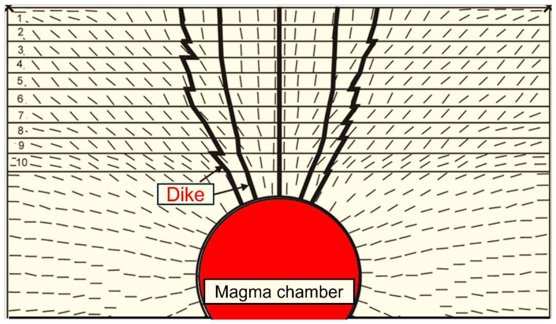
The two-dimensional model is composed of 10 layers above the unit or layer that hosts the source magma chamber (
Figure 11). All the layers have a Poisson’s ratio of 0.25, as is common for solid rocks [
17]. The variation in elastic properties between layers is thus reflected in changes in Young’s modulus or stiffness between layers. Layer 1, which is the topmost layer and forms the surface of the volcanic system, has a Young’s modulus of 10 GPa. For each subsequent deeper layer, Young’s modulus increases by 2 GPa. This means that the second layer has a Young’s modulus of 12 GPa, the third layer a Young’s modulus of 14 GPa, and so on until the 10th layer which has a modulus of 28 GPa. The layer or unit below the 10th layer is the one hosting the magma chamber, and is, in accordance with the step-like increase of 2 GPa across each contact, assigned a Young’s modulus of 30 GPa. The model loading is magmatic excess pressure of 10 MPa in the chamber. As is usual in this type of models, there is fastening (see crosses) at the model corners (indicated by crosses).
The results show that even if the variation in Young’s modulus between layers is very small—only 2 GPa—still the effects on the potential paths, and thereby on the likelihood of large-scale failure of the volcanic edifice, are comparatively large.
Figure 11 illustrates five potential dike paths from the roof of the chamber. The central one is straight, and the two adjacent ones are comparative smooth. The geometry of the outermost potential dike paths, however, is irregular, with abrupt changes from subvertical (steeply dipping) to horizontal, the latter being along contacts between layers.
Hamilton’s principle (Equation (11)) indicates that if dike initiation was equally likely everywhere in the roof of the chamber, then the three central ones would normally be selected—particularly the central straight one, since it is the shortest one. But the probability of dike initiation depends on the tensile stress concentration around the chamber, which is generally not uniform. The highest stress concentrations around magma chambers depend primarily on the mechanical layering, the loading, the shape of the chamber, and its depth below the surface in relation to its size. For a chamber with a circular vertical cross-section, the highest tensile stress concentration may be at the top—particularly if the only loading is horizontal tensile stress such as may occur at divergent plate boundaries (
Figure 10). For a chamber with a circular vertical cross-section but subject to internal excess pressure as the only loading—and particularly if the chamber is comparatively close to the surface—the maximum tensile stress concentration in the roof of the chamber is no longer at its top but rather some distance from the top (
Figure 9). In that case, the outermost potential dike paths might be selected rather than the vertical ones above the centre of the roof of the chamber.
Thus, even if the contrast in Young’s modulus between layers is small, that contrast does still have significant effects on dike paths and, therefore, on the likelihood of the dike reaching the surface to cause a significant volcano failure. Many similar models have been made of potential dike propagation paths, some with much greater contrast in Young’s modulus between layers—and thus applicable to stratovolcanoes [
17,
45]. They all indicate that dike propagation through stratovolcanoes is much more difficult than through shield volcanoes. In particular, the models suggest that many injected dikes in stratovolcanoes would tend to become arrested, and thus never make it to the surface to cause a major volcano failure as well as an eruption. This is, indeed, in agreement with direct field observations which show that a very high proportion of injected dikes in stratovolcanoes become arrested [
45].
By implication, the same results apply to all tectonic fractures. Because of much greater contrast in mechanical properties of the layers and units that constitute stratovolcanoes than those that constitute shield volcanoes, there is a much greater tendency to fracture deflection and arrest at and close to contacts in stratovolcanoes than in shield volcanoes. This means that stratovolcanoes are more fracture-resistant, have a higher toughness and are therefore mechanically stronger than shield volcanoes.
8. Hazards
Consider now how the modes and ease of (and resistance to) failure in shield volcanoes and stratovolcanoes relates to volcanic hazards. Let us first consider some definitions. Volcanic hazard is defined as the probability that an eruption will occur in a given volcano/volcanic zone/field within a specified window of time. The concept of volcanic hazard relates to that of volcanic unrest. The latter is defined as any significant increase in various detected geophysical, geochemical, and geological signals indicating changes in the rates or styles of associated physical processes within the volcano. The signals include changes in earthquake activity, ground deformation, emission of volcanic gases, and flow and chemistry of groundwater.
Many episodes of volcanic unrest—but certainly not all—are related to new magma being injected into the shallow chamber of the volcano, resulting in its expansion and surface inflation. Increasing tensile stress concentration around the chamber—by adding magma to it, by external loading through extension, or both—may result in magma-chamber rupture and dike/sheet injection. Although most unrest periods do not result in a volcanic eruption, any volcanic unrest period gives rise to the following questions when assessing volcanic hazards:
Is the magma chamber going to rupture, with a dike or sheet injection?
If the answer to first question is yes, what is then the likely propagation path of the resulting dike/sheet?
Is the dike/sheet likely to reach the surface to erupt, and then where?
If the answer to the third question is yes, then how large the eruption is likely to be?
To answer these questions and to make a reliable assessment of the hazard involved during an unrest period, one must understand what goes on inside the volcano during the unrest and, in particular, the conditions for volcano failure. We have seen that these conditions depend on various factors, but primarily the mechanical properties of the layers (and their contacts) that constitute the volcano. When a rock fracture is propagating towards a contact, it may become arrested at or just below the contact, or deflected into the contact [
5,
45] by the three principal mechanisms of Cook–Gordon delamination, stress barrier, and elastic mismatch discussed above.
In this paper we have shown that because stratovolcanoes are composed of layers and contacts whose mechanical properties vary much more widely than those that constitute shield volcanoes, stratovolcanoes have a higher toughness, that is, are mechanically stronger, more fracture-resistant, than shield volcanoes. This means that it is easier for any type of a tectonic fracture to propagate through a shield volcano than through a stratovolcano. This conclusion implies that during unrest periods with dike or inclined sheet injection, the probability of the dike/sheet reaching the surface to erupt is considerably higher in a shield volcano than in a stratovolcano. In other words, the volcanic hazard is greater during an unrest period in a shield volcano than in a stratovolcano. This assessment applies only to the probability of a dike-fed eruption during an unrest period and not to the likely type of eruption (such as its size and it being explosive or effusive) and how that may affect the estimated hazards.
And these results also apply to other types of hazards in these volcanoes that concern fracture propagation, such as caldera collapses and large landslides. For example, while stratovolcanoes are much more common than shield volcanoes and with much steeper slopes, particularly in their upper parts, most very large landslides are associated with shield volcanoes. This applies particularly to the Hawaiian shield volcanoes, where there are gigantic submarine landslides [
28]. Stratovolcanoes have frequent, but mostly comparatively small, landslides [
15], whereas shield volcanoes, while also producing numerous small landslides [
62,
63], are those that produce the really large volcanic landslides [
28,
62].
It might be suggested that since the largest shield volcanoes are much larger than the largest stratovolcanoes, then it would follow that the largest landslides should be associated with the volcanoes. On closer examination, it is seen that this suggestion is not very plausible. This is because to generate a large landslide—or a lateral collapse—a large tectonic fracture would normally be needed. By large fracture we here mean one with a comparatively large lateral and/or vertical dimensions, that is, large strike-dimension and/or dip-dimension. To become large in this sense, a fracture in a volcano composed of numerous layers—as all volcanoes are—has to propagate through many layers. Since many of the layers are gently dipping, one condition that must be satisfied in order to reach a large dip-dimension is that the fracture must extend through many layers. Based on Hamilton’s principle and related theoretical considerations discussed here, long-distance propagation in the dip-dimension is easier in shield volcanoes than in stratovolcanoes. Consequently, large landslides are easier to generate, irrespective of volcano size, in shield volcanoes than in stratovolcanoes—a conclusion that is supported by observations.
Caldera collapses also appear to be more frequent in shield volcanoes than in stratovolcanoes. Of the instrumentally well-documented caldera collapses, the following occurred in basaltic edifices: Fernandina, Galapagos (1968), Plosky Tolbachik, Russia (1975–1976), Piton de la Fournaise, Reunion Island (2007), and Kilauea, Hawaii (2018). The remaining instrumentally documented significant collapses so far are Pinatubo, Philippines (1981) and the submarine Hunga Tonga-Hunga Ha’apai (2022), which are stratovolcanoes, and Miyakejima, Japan (2000), which is sometimes classified as a basaltic stratovolcano but also produces andesite and is, in the present classification, regarded as a stratovolcano. The well-documented 60 m maximum subsidence, and associated earthquakes, in Bardarbunga in Iceland in 2014–2015, cannot be regarded as ordinary significant caldera collapse [
17]. A proper caldera collapse requires subsidence of the order of hundreds of metres, including a large displacement along a ring fault—neither of which happened during the largely elastic/plastic subsidence in Bardarbunga.
Thus, even if shield volcanoes, or more generally, subaerial basaltic edifices, are much rarer than subaerial stratovolcanoes, more instrumentally documented caldera collapses—that is collapses during the past 50–60 years—have occurred in them than in stratovolcanoes. Again, this indicates that fracture propagation, here ring fault development—mostly as normal faults—is easier and more common in shield volcanoes than in stratovolcanoes, primarily because shield volcanoes are mechanically weaker, are less fracture-resistant, than stratovolcanoes.
Can volcanic hazards and eruption forecasts be reliably estimated using probabilistic or statistical methods? There have, of course, been many attempts to estimate the probability of an eruption in a given volcano during a particular time window [
64,
65,
66,
67,
68]. These estimates normally rely on statistical data, that is, empirical data collected from the volcano—sometimes with additional input data from other similar volcanoes—so as to assess the likely events in view of previous events. More specifically, the aim of these estimates is to forecast actual eruptions as regards their probability of happening, and then decide when and where in a volcano they are likely to occur and with what power or magnitude—as well as the likely products. Additionally, there are long-term hazard assessments for a given volcano; these are mostly based on the location and style of the volcano’s past activity and events.
Probabilistic methods are successful in many fields of science, such as statistical physics. Some of basic principles of statistical physics have been applied to improve our understanding of the size distribution of tectonic fractures such as dikes and faults [
60]. These distributions are then partly explained in terms of the state of stress in the rock hosting a particular tectonic fracture being favourable or unfavourable to the propagation to that type of fracture. Ultimately, the explanatory power of such a probabilistic approach rests on its being able to relate the observed statistical distributions to energy input into the system (here, a fault zone or a volcanic zone or system), the mechanical properties of the hosting rocks, and the stress concentrations and gradients that control fracture development.
In some cases, probabilistic or empirical methods are the only ones available when trying to forecast a likely scenario during a volcano unrest period. This is so, for example, when little is known about the internal structure and history of a volcano that has entered an unrest period. Then general probability methods can be applied based on analogy with events in volcanoes of the same type and located in a similar volcanotectonic environment. At the other end of the spectrum, probabilistic methods are commonly applied to volcanoes whose eruptive history and instrumentally documented behaviour prior to eruptions are well documented. Then the probability forecasts are made, often using the Bayesian approach, where the experience and knowledge of the experts making the forecast is the foundation of the prior probability distribution, to which updates can be made as more data are obtained during the unrest period. While the assumed prior probability distribution in all Bayesian models is to a degree subjective, the impact of the subjective elements decreases when more data are obtained (in general or during unrest periods), making it possible to update the forecast.
Probabilistic and physics-based approaches for eruption forecasting are complementary. This is partly seen in that many current probabilistic volcanic hazard models incorporate more of the relevant physics, reflecting the fact that accurate forecasting of geological hazards of any kind relies not only on extensive datasets but also on a deep understanding of the physical processes that give rise to the hazards.
Volcanoes and volcanic systems are highly dynamic systems in that their energy input, mechanical properties, and stress gradients are continuously changing. Thus, even when many eruptions are along the same dike over a period of a few years—generating a multiple dike [
60], as has happened during the nine Sundhnukur eruptions on the Reykjanes Peninsula from December 2023 to July 2025—pure empirical models have not been found to be reliable. For example, the estimated magma volume in the source has varied widely before the nine eruptions, as has their duration and lava volumes, and similarly for the three eruptions in the nearby Fagradalsfjall in 2021 to 2023 [
60].
When a dike-fed eruption occurs—and most eruptions are fed by dikes/inclined sheets—then the emplacement of the dike alters the stress field [
69]. The dike may also provide a favoured path to the surface for subsequent dikes, that is, encourage the formation of a multiple dike. Here, Hamilton’s principle can be applied to explain the tendency for new dike injections to follow earlier-formed dikes so as to generate a multiple dike. For example, Hamilton’s principle has been applied to explain why all the feeder dike injections that supplied magma to the nine Sundhnukur eruptions propagated as part of a multiple dike [
6].
In addition to feeder-dike-induced changes in the local stress field and potential paths for subsequent dike injections, faulting may change the stress field, and thus the potential for subsequent eruptions. Although normal and strike–slip faulting is most common in volcanoes and volcanic systems, reverse faulting also occurs. For example, there are well-known examples of reverse faulting induced by the magmatic overpressure of nearby dikes in some parts of Iceland [
69]. Occasionally, there are significant caldera collapses, either along normal-fault or reverse-fault ring fractures, and these not only have widespread effects on the local stress field, but may also reduce greatly—at least for a while—the size of the magma source.
The above considerations do not apply only to the propagation of extension fractures, including dikes and inclined sheets, but also to the propagation of shear fractures such as those generating landslides and caldera collapses. Even when they are based on large empirical datasets, empirical and probabilistic models on large-scale volcano failure (and estimates of associated hazards) benefit from a deep understanding of not only the geology but also the physics of volcanoes. Such an understanding must be partly based on the appropriate use of the mechanical principles that control local stresses and their gradients around the magma sources and within the volcano. In particular, the models should ideally include the conditions for magma-driven fracture initiation, propagation and (eventual) arrest, the rate of magma transport (and associated heat flow) through such fractures, and the conditions for large-scale failure (lateral and vertical) of the volcano. This conclusion is in harmony with the basic theme of the present paper, namely that during unrest periods their internal mechanical structure largely controls the probability of large-scale failure of stratovolcanoes and shield volcanoes.
9. Discussion
Understanding how easily a large-scale tectonic fracture is able to propagate through a volcanic edifice is of fundamental importance for reliable assessments of volcanic hazards. In particular, such an understanding is necessary for a sound estimation of the probability of an eruption during an unrest period. Additional points in such an estimation, whether for shield volcanoes or stratovolcanoes, is the likely location and size of the eruption. Eruptions are primarily related to the propagation of magma-driven extension fractures, dikes or inclined sheets. By contrast, lateral and vertical collapses, that is, landslides and caldera collapses, are mostly related to the propagation of shear fractures.
Large-scale shear-fracture propagation is the main reason for the development of lateral collapses or landslides as well as for vertical collapses or caldera collapses (
Figure 6 and
Figure 7). Shear fractures, just like extension fractures, depend for their propagation on their continuing to be within rock bodies whose local stresses are favourable to that type of fracture development. I have shown in the present paper that the tendency to fracture deflection and arrest is much stronger in stratovolcanoes than in shield volcanoes, which implies that the likelihood of large-scale lateral and vertical collapses is less in stratovolcanoes than in shield volcanoes.
Assessing the likelihood of lateral and vertical collapses in volcanoes is of great importance. This is so for several reasons. First, lateral collapses, such as large landslides in ocean islands, can generate tsunamis. There is little doubt that the large landslides around ocean islands such as Hawaii [
13,
24,
29] generated large tsunamis. And tsunamis, primarily related to earthquakes, have had devastating effects as regards lost lives and properties in the past decades [
70,
71,
72].
Second, large caldera collapses can give rise to some of the largest eruptions on the planet. The most recent of such caldera-related ‘super-eruptions’ is the one in Toba some 75 thousand years ago [
73]. The volume of erupted material in this eruption is estimated at 2800 km
3—on the scale that, for a similar one to happen today, it would threaten human civilisation. It is thus paramount to be able to understand the conditions inside a volcano—and the hosting crustal segment—that allows such eruptions to occur. That understanding is likely to help in reliable hazard assessment, and thereby forms the basis for a necessary evacuation. Such an understanding may also provide the theoretical framework within which it may be possible, in the future, to prevent eruptions on a similar scale from happening [
17].
Many large caldera eruptions are explosive. In fact, it has been estimated that most explosive eruptions that exceed about 25 km
3 in eruptive materials are erupted from calderas [
41]. However, equally large volumes are generated through basaltic fissure eruptions. Some of these are of the same order of magnitude as the largest caldera-driven explosive eruptions. The volumes of single lava flows in the very largest fissure eruptions have been estimated at 5000 km
3 [
74]. Some of these can be connected to a large graben subsidence, in which case the mechanism of squeezing out the magma from the source is similar to that operating during caldera collapse [
17].
‘Super-eruptions’ are fortunately very rare. Eruptions with volumes in excess of 1000 km
3 occur perhaps once every 50 thousand years [
17]. But there are many eruptions with much smaller eruptive volumes than this that can still have devastating effects on nearby areas. In order to provide reliable forecasts of such—and, for that matter, any—eruptions, the state of stress and its variation inside the volcano/volcanic system must be assessed. The state of stress decides, first, if the magma source is going to rupture and inject a magma-filled fracture and, second, the likely path of that fracture.
Once a magma source has ruptured and a magma-filled fracture is propagating up into the roof of the source, the eventual fate of the fracture propagation depends on the details of the local stress field. In particular, the local stress field and the mechanical layering determine whether or not the injected magma-filled fracture is able to reach the surface to erupt or, alternatively, becomes arrested at depth in the volcano/volcanic system. And if an eruption occurs, the local stress and layering determine where the magma-filled fracture reaches the surface, and whether that eventual fracture is a subvertical dike or an inclined sheet.
When the mechanical layering is reasonably well known, Hamilton’s principle can be used to forecast and explain the paths that injected dikes select. From the surface geology, seismic studies, and numerous geothermal boreholes, the mechanical layering on the Reykjanes Peninsula in Iceland is rather well known [
43]. Since the principle effectively demands that propagating dikes orientate themselves in a direction perpendicular to σ
3 and parallel with σ
1, stress modelling for the layered crust, such as in
Figure 11 [
17,
45], makes it possible to explain the dike paths observed (through seismicity and deformation studies) during the 2021 dike injection in Fagradalsfjall—in particular, why the main part of the dike became arrested at about 2 km depth and never reached the surface [
43]. Similarly, the principle explains why all the dike injections in Fagradalsfjall and Sundhnukur (Reykjanes Peninsula) during the period 2021–2025 have resulted in the formation of multiple dikes [
6,
43]. While this application of Hamilton’s principle is for extension fractures, there is already a wide use of the principle in phase-field engineering fracture mechanics studies [
6]. The damage zone generated in phase-field modelling suggests it may be applicable to the propagation paths of faults, such as those associated with landslides and caldera collapses.
The processes by which volcanic edifices fail on a large scale, and how they fail, thus depends on the internal structure of the edifice. A stratovolcano can store much more strain energy before failure than a shield volcano. This is primarily because of the different types of layering. In the shield volcano, nearly all the layers are basaltic and mostly similar in mechanical properties, which means that the local stress fields tend to be similar along the likely path of a large fracture. In a stratovolcano the layers are of a wide variety of lithologies with a strong contrast in mechanical properties. Consequently, the local stress fields along most potential paths for large fractures are commonly highly dissimilar and, therefore, tend to deflect and arrest fracture propagation.
Because stratovolcanoes can store more strain energy than shield volcanoes before large-scale failure means that the rock layers that constitute stratovolcanoes together have normally a significantly higher toughness than those that constitute shield volcanoes. Thus, a greater energy input is needed to propagate a non-stratabound (non-layerbound) fracture in a stratovolcano than in a shield volcano. In other words, shield volcanoes are mechanically weaker, are more easily fractured on a large scale, than stratovolcanoes.
10. Conclusions
Because a stratovolcano is composed of layers with widely different elastic properties, it tends to be much tougher than a shield volcano. The high toughness of a typical stratovolcano is a principal reason why dike-fed eruptions and large lateral and vertical collapses are comparatively rare during unrest periods. Thus, stratovolcanoes become mechanically strong (resistant to tectonic fracture propagation) because they function as high-toughness composite structures made of layers that encourage fracture deflection and arrest, with clear implications for associated hazards. The strain energy required to propagate a tectonic fracture for a given distance (and through many layers) in a stratovolcano is therefore normally much larger than that required to propagate a fracture of an equal distance in a basaltic edifice. In other words: strain energy that is sufficiently large to propagate a feeder dike, a caldera fault, or a landslide fault through many layers and to the surface in a shield volcano is commonly too small to propagate a similar fracture to the surface in a stratovolcano.