
Static Model-Based Optimization and Multi-Input Optimal Control of Automatic Transmission Upshift during Inertia Phase

 ,
, 
Abstract
:1. Introduction
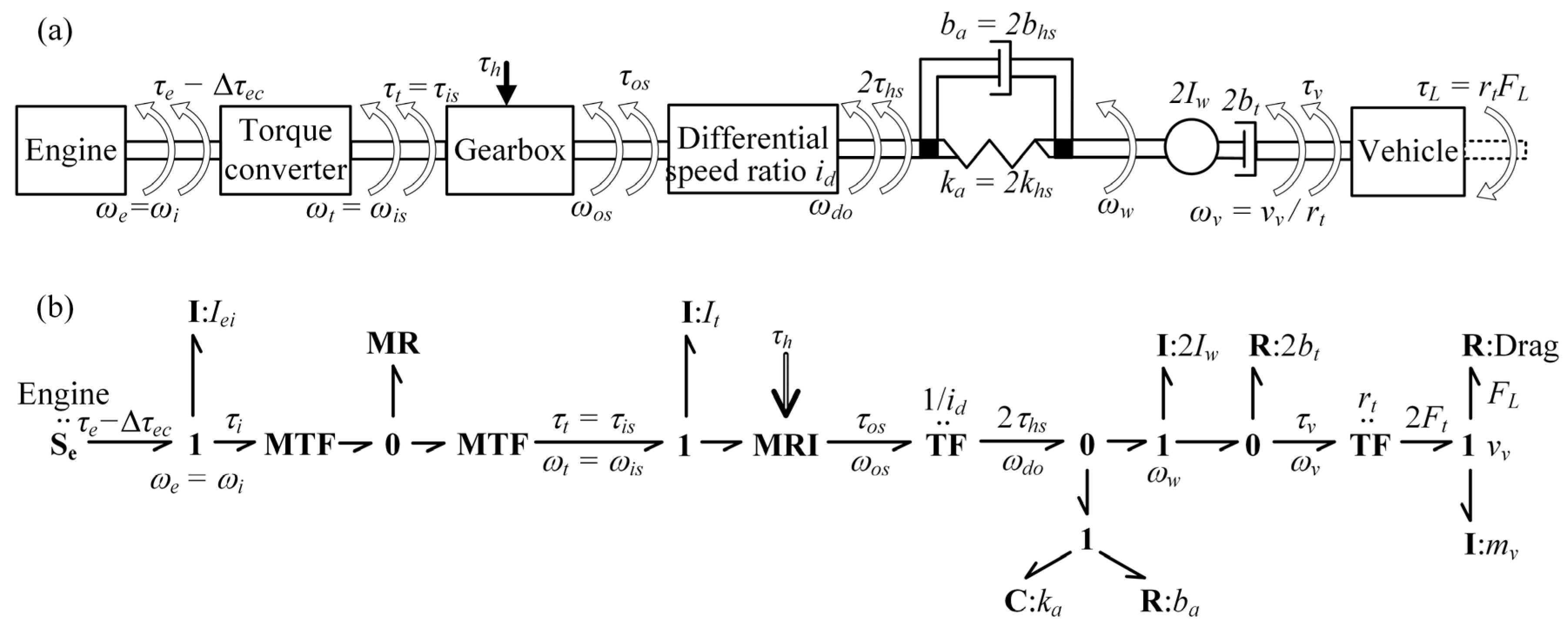
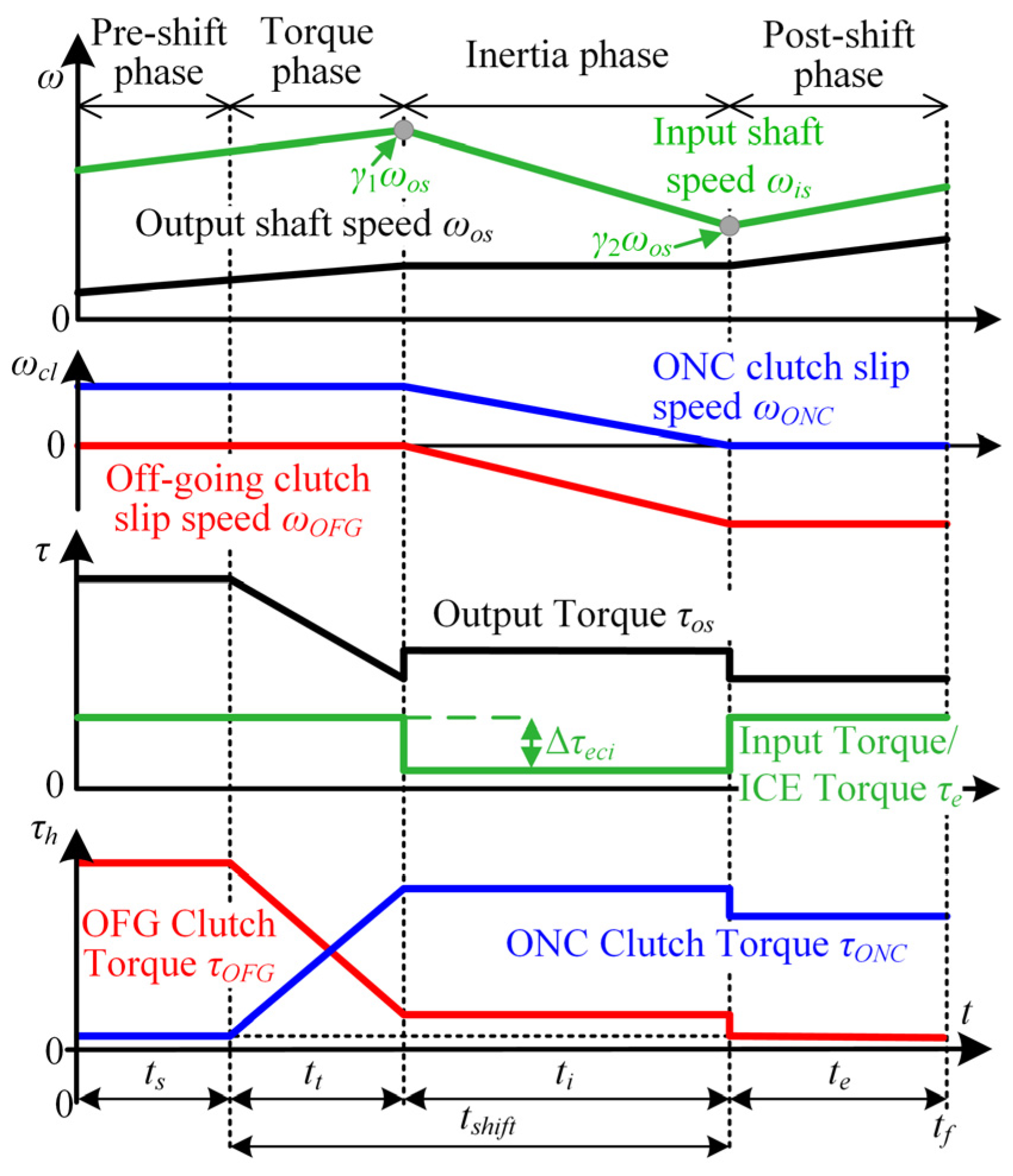
2. Powertrain Dynamics Model
3. Control Parameter Optimization
3.1. Problem Formulation
- ONC clutch only,
- ONC and OFG clutch,
- ONC clutch and engine torque reduction,
- ONC and OFG clutch including engine torque reduction.
3.2. Optimization Results
4. Static Model-Based Optimization
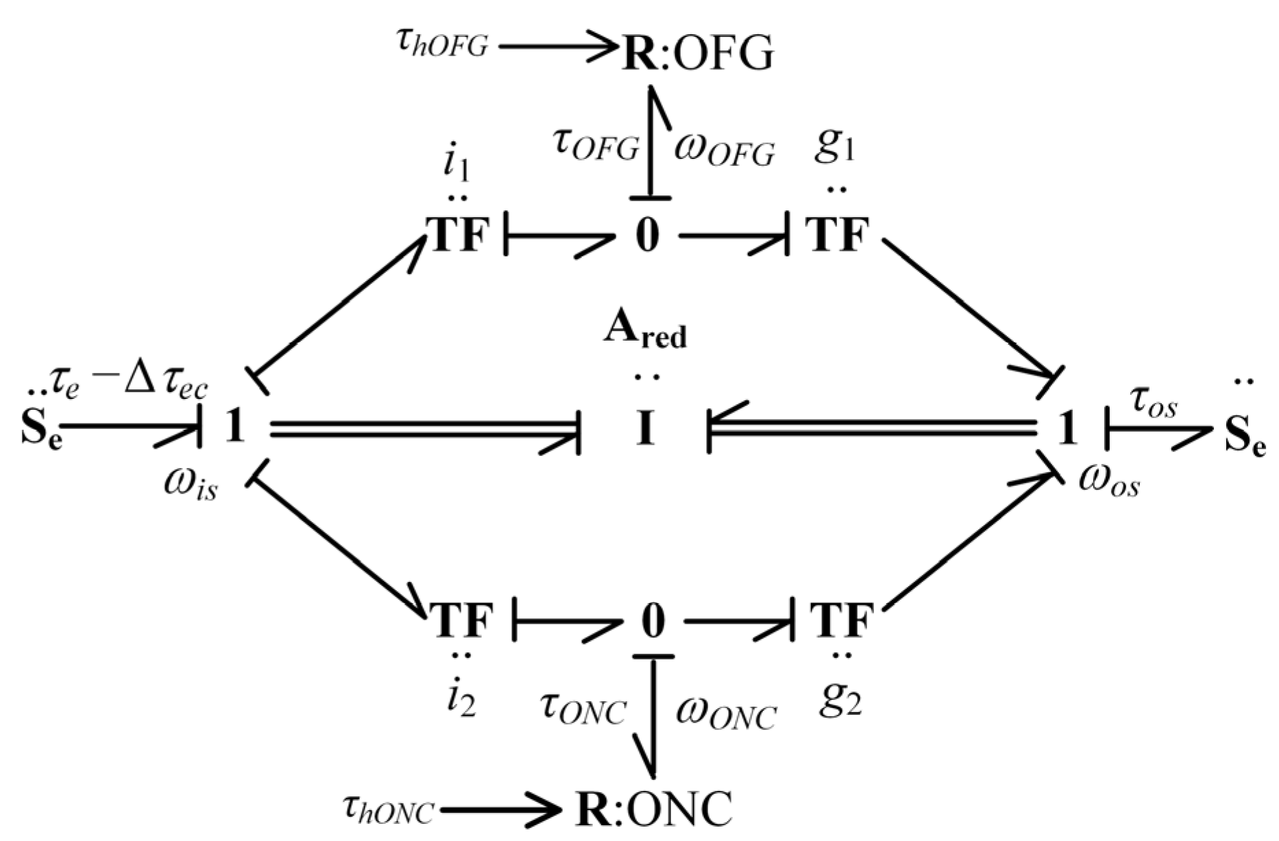
4.1. Model Simplification
4.2. Definition of Optimization Objectives
4.2.1. Inertia Phase Duration
4.2.2. Energy Loss in Inertia Phase
4.2.3. Shift Comfort Equivalent
4.3. Final Expressions for Optimization Objectives
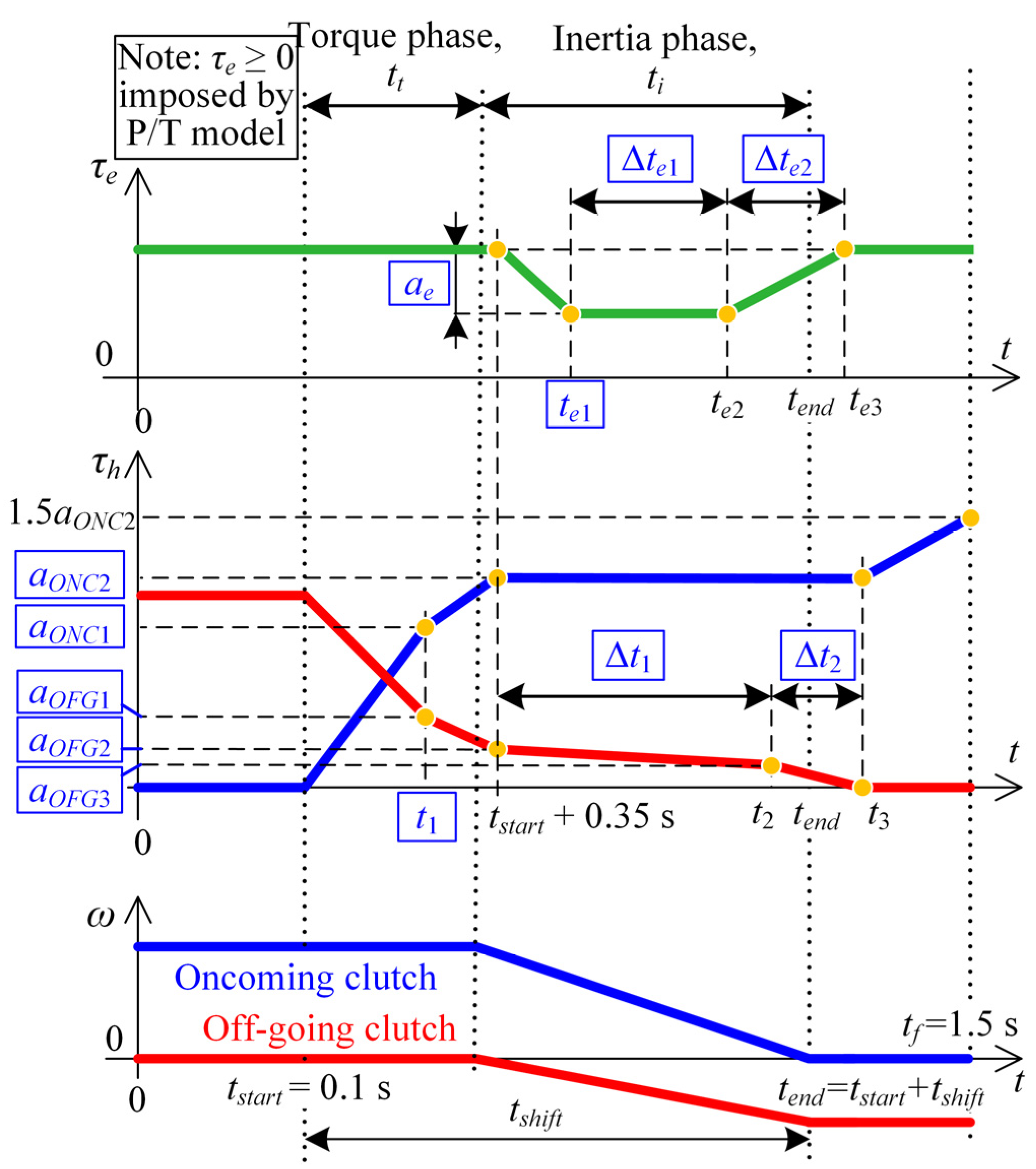
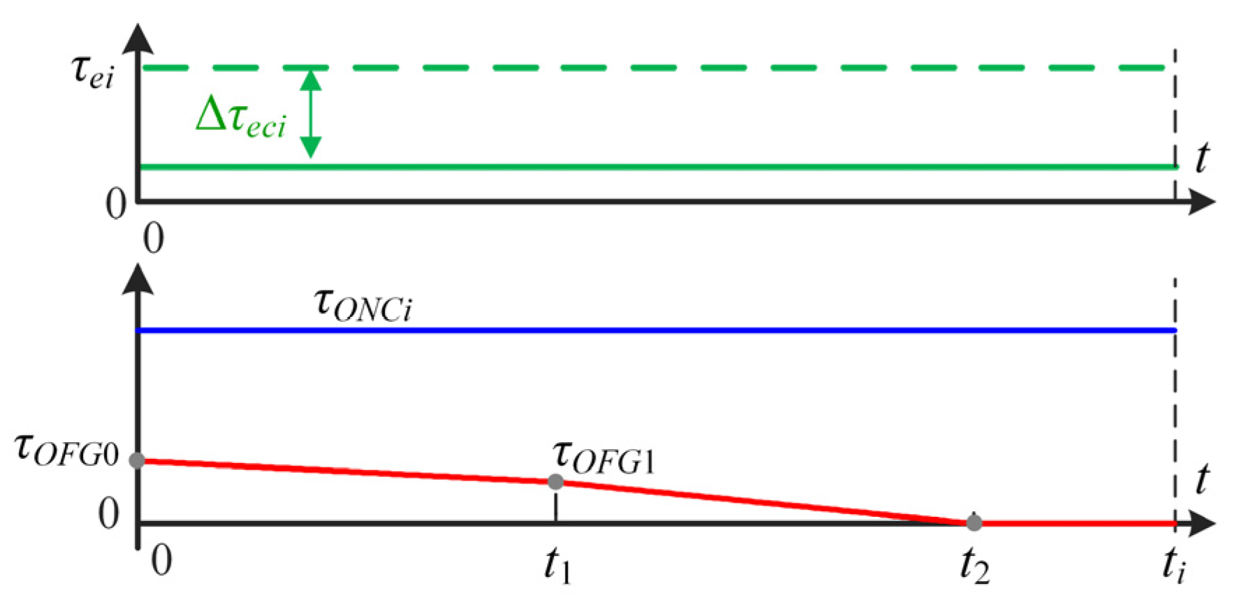
4.3.1. Constant Control Inputs
4.3.2. Piecewise Linear Profile of Off-Going Clutch Torque Control Input
4.4. Optimization Framework
4.5. Algebraic Analysis for Constant Control Input Case
4.5.1. Inertia Phase Duration
4.5.2. Total Clutch Energy Loss
5. Optimization Results and Performance Analysis
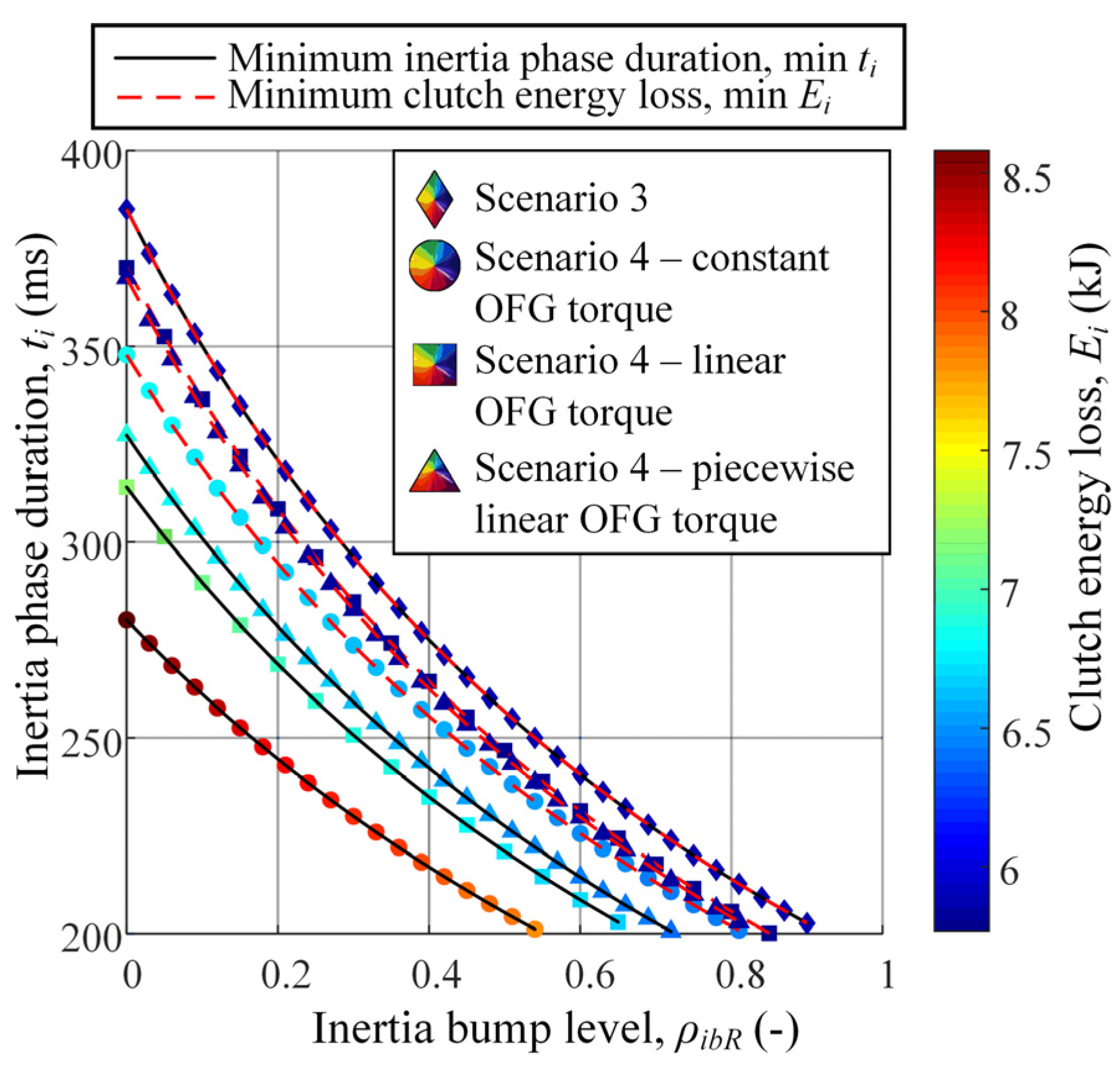
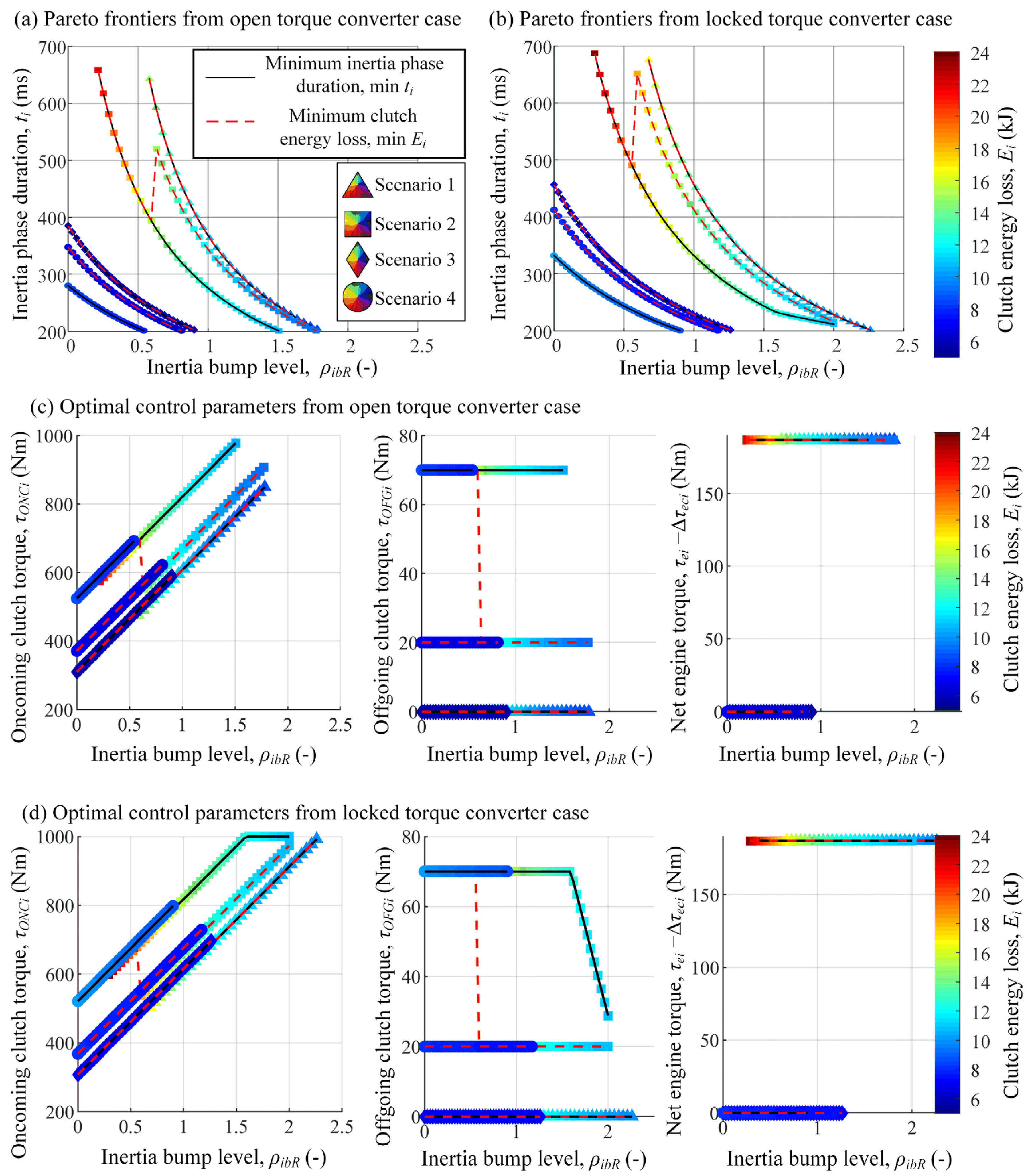
5.1. Optimization Results
5.1.1. Constant Control Inputs
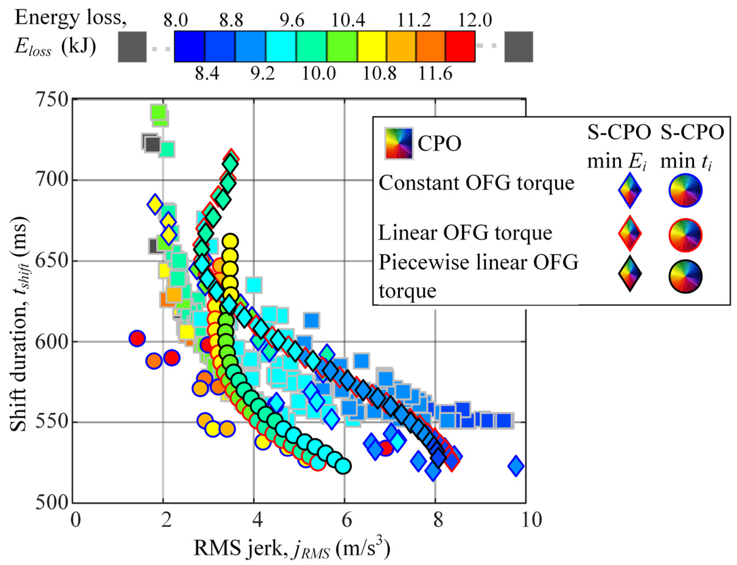
5.1.2. Piecewise Linear Profile of Off-Going Clutch Torque Control Input
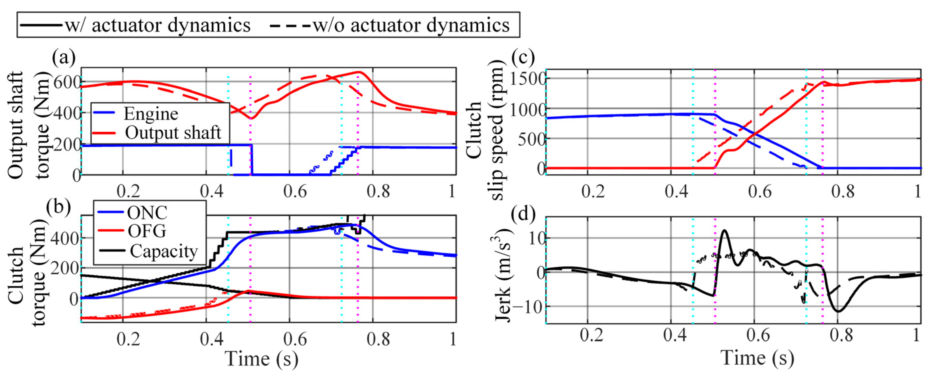
5.2. Simulation-Based Performance Analysis
6. Static Model-Based Predictive Control
6.1. Control System Design
6.1.1. Basic Control Law
6.1.2. Control Signal Difference Dead Zone
6.2. Simulation Verification Results
7. Conclusions
Author Contributions
Funding
Data Availability Statement
Acknowledgments
Conflicts of Interest
Nomenclature
| Symbols | Subscripts | ||
| I | Inertia | e | Engine |
| i | AT input shaft-clutch torque ratio | is | Input shaft |
| g | Clutch-AT output shaft torque ratio | io | Input-to-output shaft |
| Eloss | Dissipated energy in clutches | os | Output shaft |
| jRMS | Root mean square of vehicle jerk | ONC | Oncoming (clutch) |
| t | Time | OFG | Off-going (clutch) |
| tshift | Shift time | 1 | Off-going clutch path |
| ω | Speed | 2 | On-coming clutch path |
| τ | Torque | ||
| γ | Gear ratio | ||
Abbreviations
| Abbreviation | Meaning |
| AT | Automatic transmission |
| CPO | Control parameter optimization |
| CTO | Control trajectory optimization |
| OFG | Off-going clutch |
| ONC | Oncoming clutch |
| RMS | Root mean square |
| S-CPO | Static model-based control parameter optimization |
| S-MPC | Static model-based predictive control |
| SQP | Sequential quadratic program |
Appendix A. Clutch Energy Loss for Piecewise Linear Shape of Off-Going Clutch Torque
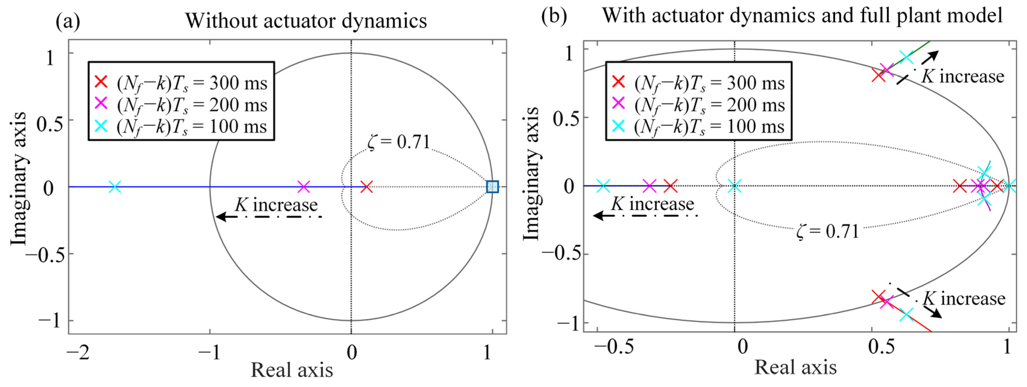
Appendix B. Root-Locus Analysis of Ringing and Instability Effects

References
- Bai, S.; Maguire, J.; Peng, H. Dynamic Analysis and Control System Design of Automatic Transmissions; SAE International: Warrendale, PA, USA, 2013. [Google Scholar] [CrossRef]
- Greiner, J.; Grumbach, M. Automatic Transmission Systems Beyond 2020- Challenger and Competition. SAE Tech. Paper; 2013; p. 2013-01-1273. [Google Scholar] [CrossRef]
- Li, D. Control and Integration Challenges for Future Automatic Transmissions. SAE Int. J. Engines 2016, 9, 1881–1890. [Google Scholar] [CrossRef]
- Wurm, M.S.A.; Bestle, D. New Approach for Transmission Calibration—Model-based Multi-Objective Optimization Via SIL. In Proceedings of the 7th International Symposium and Exhibition, Innovative Automotive Transmission, Hybrid & Electric Drives, Detroit, MI, USA, 13–15 May 2013. [Google Scholar]
- Ranogajec, V.; Coric, M.; Deur, J.; Ivanovic, V. Multi-objective Parameter Optimization of Automatic Transmission Shift Control Profiles. SAE Tech. Paper 2018, 2018-01-1164. [Google Scholar] [CrossRef]
- Ranogajec, V.; Deur, J.; Ivanović, V.; Tseng, H.E. Multi-objective parameter optimization of control profiles for automatic transmission double-transition shifts. Control Eng. Pract. 2019, 93, 104183. [Google Scholar] [CrossRef]
- Zhang, H.; Zhao, X.; Yang, J.; Zhang, W. Optimizing Automatic Transmission Double-Transition Shift Process Based on Multi-Objective Genetic Algorithm. Appl. Sci. 2020, 10, 7794. [Google Scholar] [CrossRef]
- Čorić, M.; Ranogajec, V.; Deur, J.; Ivanović, V.; Tseng, H.E. Optimization of Shift Control Trajectories for Step Gear Automatic Transmissions. J. Dyn. Syst. Meas. Control 2017, 139, 061005. [Google Scholar] [CrossRef]
- Ranogajec, V.; Ivanović, V.; Deur, J.; Tseng, H.E. Optimization-based assessment of automatic transmission double-transition shift controls. Control Eng. Pract. 2018, 76, 155–166. [Google Scholar] [CrossRef]
- Gao, B.; Chen, H.; Sanada, K. Two-Degree-of-Freedom Controller Design for Clutch Slip Control of Automatic Transmission. SAE Int. J. Passeng. Cars-Mech. Syst. 2009, 1, 430–438. [Google Scholar] [CrossRef]
- Mishra, K.D.; Srinivasan, K. Robust control and estimation of clutch-to-clutch shifts. Control Eng. Pract. 2017, 65, 100–114. [Google Scholar] [CrossRef]
- Mishra, K.; Srinivasan, K. Improved Integrated Powertrain Control of Gearshifts Using Linear Parameter Varying Control. In Proceedings of the 2019 American Control Conference (ACC), Philadelphia, PA, USA, 10–12 July 2019; pp. 4553–4558. [Google Scholar] [CrossRef]
- Liu, F.; Chen, L.; Li, D.; Yin, C. Improved Clutch Slip Control for Automated Transmissions. Proc. Inst. Mech. Eng. Part C J. Mech. Eng. Sci. 2018, 232, 3181–3199. [Google Scholar] [CrossRef]
- Cvok, I.; Deur, J.; Ivanovic, V.; Zhang, Y.; Fujii, Y. An LQR Approach of Automatic Transmission Upshift Control Including Use of Off-going Clutch within Inertia Phase. SAE Int. J. Adv. Curr. Pract. Mobil. 2020, 2, 2081–2091. [Google Scholar] [CrossRef]
- Soldo, J.; Cvok, I.; Deur, J.; Ivanovic, V.; Zhang, Y.; Fujii, Y. Automatic Transmission Upshift Control Using a Linearized Reduced-Order Model-Based LQR Approach. SAE Int. J. Adv. Curr. Pract. Mobil. 2021, 3, 2290–2300. [Google Scholar] [CrossRef]
- Liu, Q.; Guo, L.; Gao, B.; Ye, K.; Chen, H.; Guo, H. Coordinate Receding Horizon Control for the Power-Shift Process of Multispeed Electric Vehicles. IEEE Trans. Veh. Technol. 2019, 69, 1055–1059. [Google Scholar] [CrossRef]
- Mesmer, F.; Szabo, T.; Graichen, K. Embedded Nonlinear Model Predictive Control of Dual-Clutch Transmissions with Multiple Groups on a Shrinking Horizon. IEEE Trans. Control Syst. Technol. 2018, 27, 2156–2168. [Google Scholar] [CrossRef]
- Ranogajec, V.; Deur, J.; Coric, M. Bond Graph Analysis of Automatic Transmission Shifts including Potential of Extra Clutch Control. SAE Int. J. Engines 2016, 9, 1929–1945. [Google Scholar] [CrossRef]
- Zhang, Y.; Haria, H.; Hippalgaonkar, R.; Pietron, G.; Fujii, Y. Automatic Transmission Shift Control for Canceling Inertia Torque. SAE Tech. Paper 2018, 2018-01-1167. [Google Scholar] [CrossRef]
- Cvok, I.; Ranogajec, V.; Deur, J.; Zhang, Y.; Ivanovic, V.; Fujii, Y. Analysis of Improving Automatic Transmission Upshift Performance by Using Off-Going Clutch during Inertia Phase. J. Dyn. Syst. Meas. Control 2021, 144, 021005. [Google Scholar] [CrossRef]
- Hrovat, D.; Tobler, W. Bond Graph Modeling of Automotive Power Trains. J. Frankl. Inst. 1991, 328, 623–662. [Google Scholar] [CrossRef]
- Deur, J.; Asgari, J.; Hrovat, D.; Kovač, P. Modeling and Analysis of Automatic Transmission Engagement Dynamics-Linear Case. J. Dyn. Syst. Meas. Control 2005, 128, 263–277. [Google Scholar] [CrossRef]
- Goleski, G.D.; Baldwin, R.A. Multi-Speed Transmission. U.S. Patent 8,545,362 B1, 1 October 2013. [Google Scholar]
- Ivanovic, V.; Tseng, H.E. Bond Graph Based Approach for Modeling of Automatic Transmission Dynamics. SAE Int. J. Engines 2017, 10, 1999–2014. [Google Scholar] [CrossRef]
- Ranogajec, V.; Deur, J. An Automated Model-Order Reduction Method for Automatic Transmissions. J. Dyn. Syst. Meas. Control 2017, 139, 071004. [Google Scholar] [CrossRef]
- Ranogajec, V.; Deur, J. Bond Graph Analysis of Automatic Transmission Double-Transition Shift Dynamics. In Proceedings of the International Conference on Bond Graph Modeling (ICBGM 2018), Bordeaux, France, 9–12 July 2018; p. 11. [Google Scholar]
- Karnopp, D. Computer Simulation of Stick-Slip Friction in Mechanical Dynamic Systems. J. Dyn. Syst. Meas. Control 1985, 107, 100–103. [Google Scholar] [CrossRef]
- Zhang, Y.; Fujii, Y.; Hippalgaonkar, R.; Cvok, I.; Ivanovic, V.; Deur, J.; Ranogajec, V. Mathematical Analysis of Clutch Thermal Energy during Automatic Shifting Coupled with Input Torque Truncation. SAE Tech. Paper 2020, 2020-01-0967. [Google Scholar] [CrossRef]
- Isermann, R. Digital Control Systems; Springer: Berlin/Heidelberg, Germany, 1989. [Google Scholar] [CrossRef]


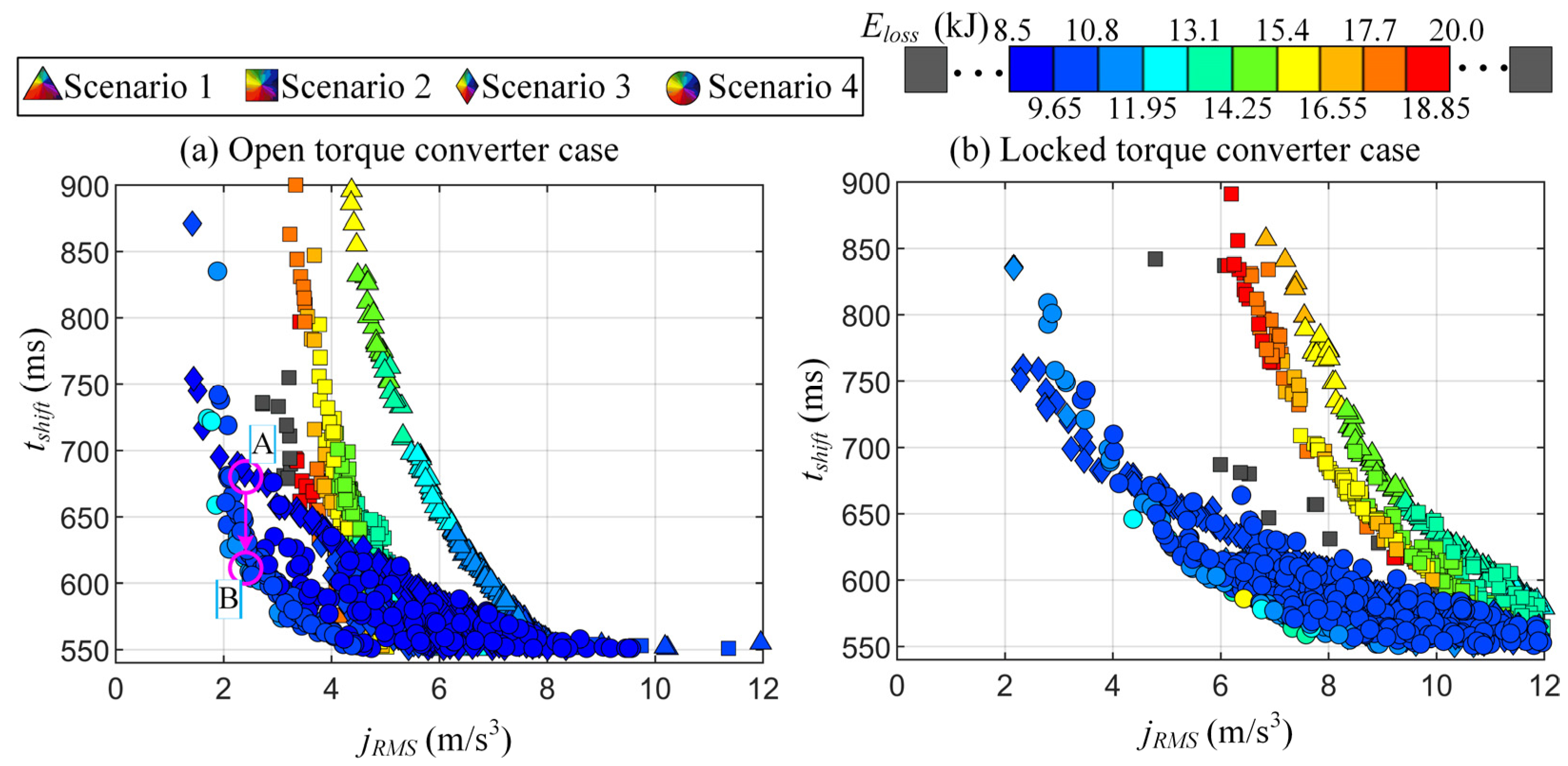
| Point | jRMS (m/s3) | tshift (ms) | Eloss (kJ) |
|---|---|---|---|
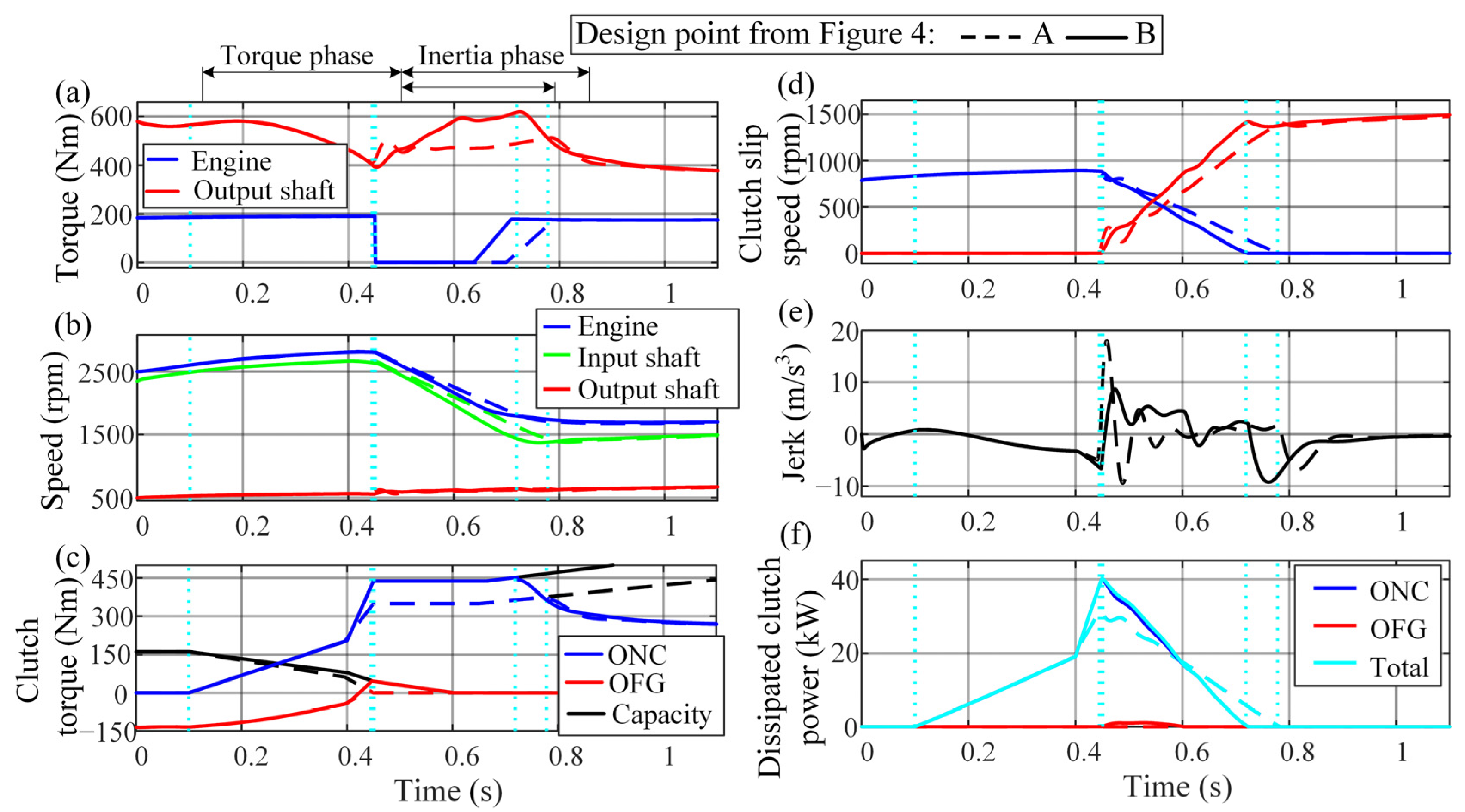
| A (Scenario 3) | 2.64 | 678 | 9.4 |
| B (Scenario 4) | 2.68 (+1.5%) | 619 (−8.7%) | 9.76 (+3.8%) |
| Scenario | Min | Mean | Max | Min | Mean | Max |
|---|---|---|---|---|---|---|
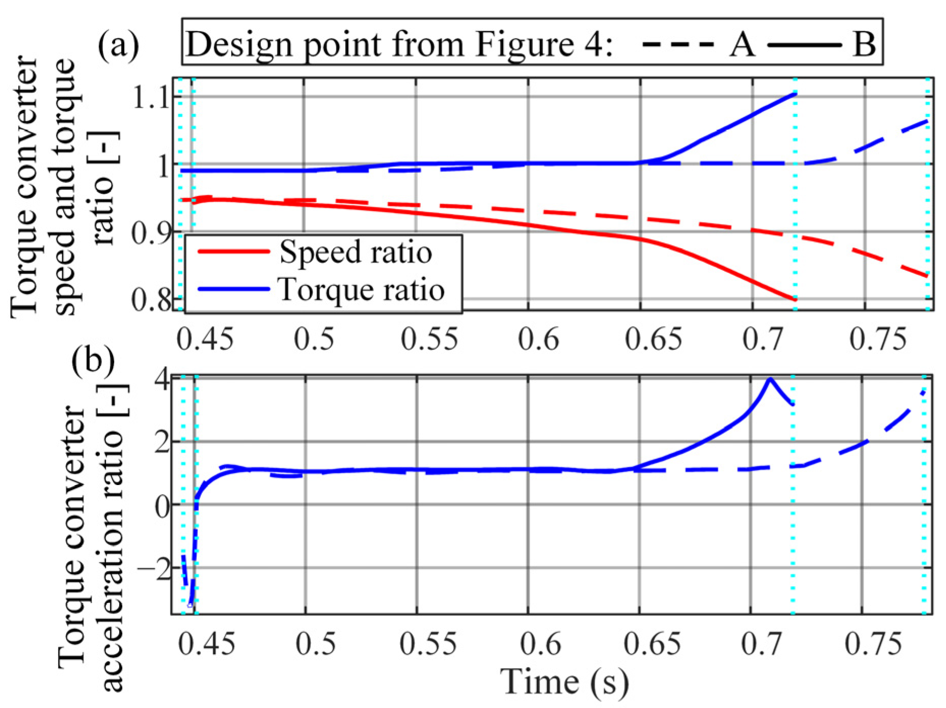
| 1 | 1.00 | 1.03 | 1.05 | 1.14 | 1.48 | 1.64 |
| 2 | 1.00 | 1.03 | 1.05 | 1.22 | 1.51 | 1.81 |
| 3 | 1.00 | 1.00 | 1.02 | 1.09 | 1.34 | 1.61 |
| 4 | 1.00 | 1.01 | 1.02 | 1.11 | 1.26 | 1.61 |
| Constraints | ||
|---|---|---|
| 0 Nm | ≤ τONCi ≤ | 1000 Nm |
| 20 Nm | ≤ τOFGi ≤ | 70 Nm |
| 0 Nm | ≤ Δτeci ≤ | τei |
| Constraints | ||
|---|---|---|
| 0 Nm | ≤ τONCi ≤ | 1000 Nm |
| 20 Nm | ≤ τOFG0 ≤ | 70 Nm |
| 10 Nm | ≤ τOFG1 ≤ | 35 Nm |
| 0 Nm | ≤ Δτeci ≤ | τei |
| 50 ms | ≤ t1 ≤ | 0.4ti |
| 100 ms | ≤ t2 ≤ | 0.8ti |
| t1 ≤ t2 | ||
| tshift (ms) | ti (ms) | Eloss (kJ) | jRMS (m/s3) | |
|---|---|---|---|---|
| CPO | 619 | 268 | 9.76 | 2.69 |
| S-MPC | 625 (+1%) | 272 (+1.5%) | 9.85 (+1%) | 2.62 (−3%) |
| CPO | S-MPC | |||||||
|---|---|---|---|---|---|---|---|---|
| Iei/Iei,nom | tshift (ms) | ti (ms) | Eloss (kJ) | jRMS (m/s3) | tshift (ms) | ti (ms) | Eloss (kJ) | jRMS (m/s3) |
| 0.8 | 576 | 223 | 9.1 | 3.34 | 621 | 266 | 9.4 | 2.59 |
| (−7%) | (−17%) | (−6%) | (+24%) | (−1%) | (−2%) | (−5%) | (−1%) | |
| 0.9 | 595 | 243 | 9.4 | 2.83 | 619 | 265 | 9.6 | 2.50 |
| (−4%) | (−9%) | (−3%) | (+5%) | (−1%) | (−3%) | (−2%) | (−4%) | |
| 1.0 | 619 | 268 | 9.8 | 2.69 | 625 | 272 | 9.9 | 2.62 |
| (0%) | (0%) | (0%) | (0%) | (0% | (0%) | (0%) | (0%) | |
| 1 | 650 | 299 | 10.1 | 2.68 | 619 | 267 | 10.0 | 2.94 |
| (+5%) | (+12%) | (+3%) | (0%) | (−1%) | (−2%) | (+2%) | (+12%) | |
| 1.1 | 680 | 330 | 10.4 | 2.75 | 627 | 275 | 10.2 | 3.11 |
| (+10%) | (+23%) | (+7%) | (+2%) | (0%) | (+1%) | (+3%) | (+19%) | |
| 1.2 | 576 | 223 | 9.1 | 3.34 | 621 | 266 | 9.4 | 2.59 |
| (−7%) | (−17%) | (−6%) | (+24%) | (−1%) | (−2%) | (−5%) | (−1%) |
Disclaimer/Publisher’s Note: The statements, opinions and data contained in all publications are solely those of the individual author(s) and contributor(s) and not of MDPI and/or the editor(s). MDPI and/or the editor(s) disclaim responsibility for any injury to people or property resulting from any ideas, methods, instructions or products referred to in the content. |
© 2023 by the authors. Licensee MDPI, Basel, Switzerland. This article is an open access article distributed under the terms and conditions of the Creative Commons Attribution (CC BY) license (https://creativecommons.org/licenses/by/4.0/).
Share and Cite
Cvok, I.; Deur, J.; Hihlik, M.; Zhang, Y.; Ivanovic, V.; Fujii, Y. Static Model-Based Optimization and Multi-Input Optimal Control of Automatic Transmission Upshift during Inertia Phase. Vehicles 2023, 5, 177-202. https://doi.org/10.3390/vehicles5010011
Cvok I, Deur J, Hihlik M, Zhang Y, Ivanovic V, Fujii Y. Static Model-Based Optimization and Multi-Input Optimal Control of Automatic Transmission Upshift during Inertia Phase. Vehicles. 2023; 5(1):177-202. https://doi.org/10.3390/vehicles5010011
Chicago/Turabian StyleCvok, Ivan, Joško Deur, Mislav Hihlik, Yijing Zhang, Vladimir Ivanovic, and Yuji Fujii. 2023. "Static Model-Based Optimization and Multi-Input Optimal Control of Automatic Transmission Upshift during Inertia Phase" Vehicles 5, no. 1: 177-202. https://doi.org/10.3390/vehicles5010011
APA StyleCvok, I., Deur, J., Hihlik, M., Zhang, Y., Ivanovic, V., & Fujii, Y. (2023). Static Model-Based Optimization and Multi-Input Optimal Control of Automatic Transmission Upshift during Inertia Phase. Vehicles, 5(1), 177-202. https://doi.org/10.3390/vehicles5010011