1. Introduction
During the last twenty years, the scientific community has been developing emerging technologies aimed at green energy and decreasing carbon emissions [
1,
2,
3]. Thus, power converters [
4,
5], electrical motors [
6] and generators [
7], photovoltaic generation systems [
8], and renewable energy as a whole [
9] have received more attention and research activities. One of the results of the activity in this direction was the significant rise of electrical cars’ market share [
10,
11], which in turn intensified the development in neighboring areas, which includes electric motor drives [
12], batteries as well as technologies connected to them [
13,
14,
15], power electronics, etc. [
16].
One of the most import technologies for electrical vehicles is electrical motor drives, which are used in powertrains for traction, in air conditioning systems to cool the car cabin and its parts, in doors for its opening/closing and window movements, etc. The most popular type of motors used in automotive applications is permanent magnet (PM) synchronous motors [
17,
18]. These have high torque-to-weight and torque-to-size ratios and can demonstrate high efficiency, which makes them attractive for automotive objects for which size, weight, and power consumption are parameters that need to be carefully controlled [
19]. In order to utilize the full potential of PM synchronous motors (PMSMs), their control systems should implement several state-of-the-art techniques, which include Maximum Torque Per Ampere (MTPA) control, field-weakening (FW), harmonic suppression, etc. Therefore, FW is one of the key algorithms for automotive motor drives. This technology is used to overcome speed limitations due to the lack of supply voltage and increases the motor’s speed operation range, which is extremely important for motor drives supplied with a low or/and unstable voltage [
20,
21].
FW techniques are usually designed as extensions to conventional control schemes; therefore, they can be easily modified without redesigning the main control algorithm. At the same time, FW algorithms impact the dynamic operation of motor drives; thus, modification of the FW technique may require tuning of the main control algorithm. FW algorithms are typically implemented in such a way that they are inactive while the existing direct current (DC)-link voltage is sufficient for control, and they are activated when the DC-link voltage is insufficient.
The design of an FW algorithm depends on the type of main control scheme, and its implementation differs for direct torque control (DTC) [
22,
23], field-oriented control (FOC) [
24], and discrete-space vector modulation (DSVM) [
25] schemes; however, this paper studies only field-weakening algorithms for FOC, which are used in the control systems of the overwhelming majority of motor drives.
2. Field-Weakening Approaches
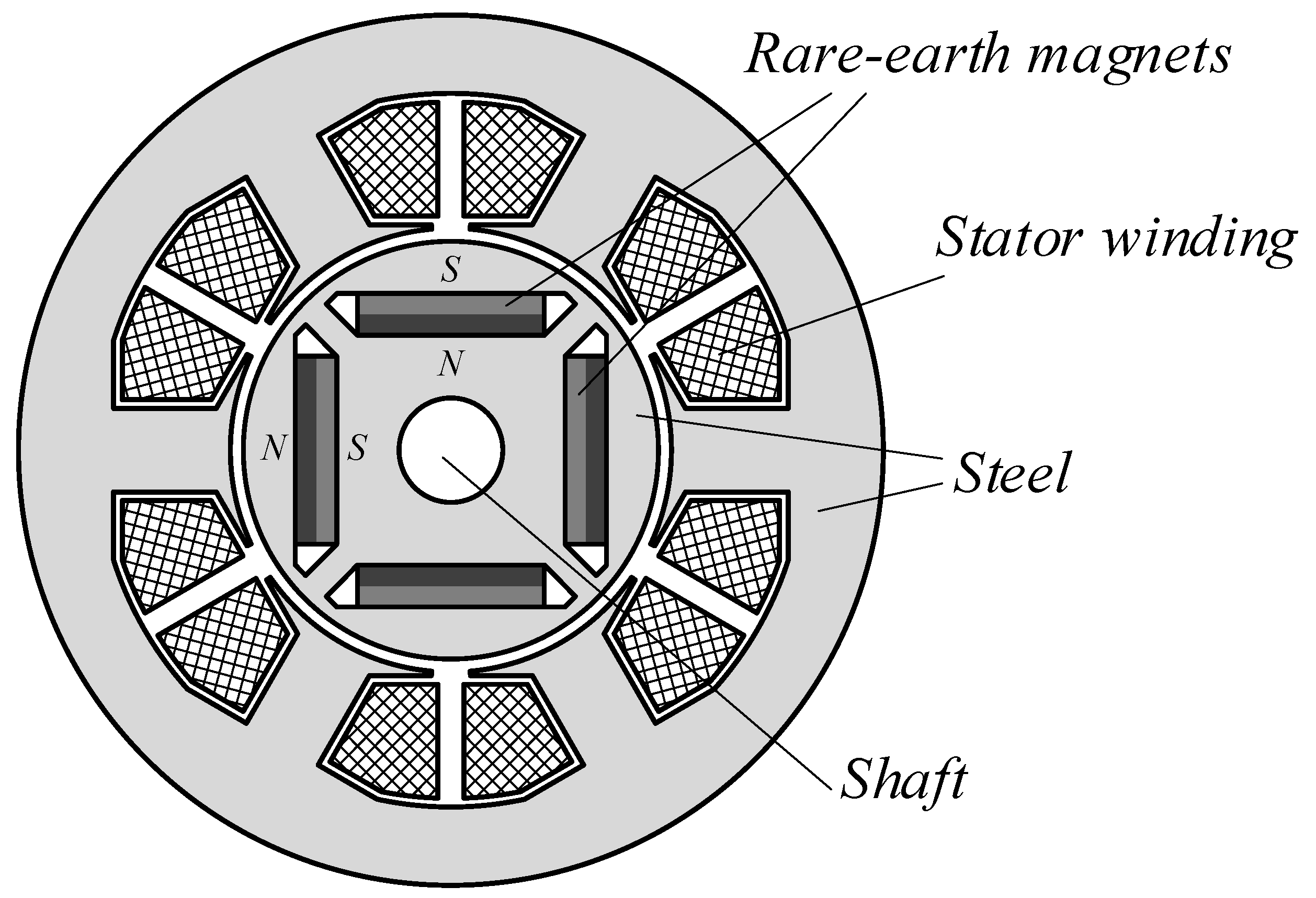
In order to discuss FW approaches, the physical principles of PMSM operation should be explained. The simplified construction of the three-phased four-poled Internal permanent magnet synchronous motor (IPMSM) is demonstrated in
Figure 1. The rotor contains permanent magnets, which create a magnetic field. This field interacts with a stator magnetic field, created by the winding in the stator and supplied from the inverter. The rotor flux-linkage is almost constant and does not significantly vary during operation [
26]; however, the stator current, which creates stator flux linkage, may be easily controlled and varies in a wider range.
When the rotor rotates, it creates alternating magnetic fields in the stator winding, which create a back-EMF. If the machine operates in motor mode, the direction of the back-EMF is opposite to the DC-link voltage; therefore, there is a theoretical limit to the motor speed, where the back-EMF is equal to the voltage applied to stator windings.
The operation of the PMSM can be illustrated with the following electrical equations:
where:
ua, ub, uc,—the motor phase voltages;
ia, ib, ic,—the motor phase currents;
Ra, Rb, Rc,—the motor phase resistances;
ψa, ψb, ψc,—the motor phase flux linkages, which are multivariable functions and depend on the motor design, its self and mutual inductances, the phase currents, etc. It should be noted that a more mathematically strict writing of this is ψa(ia(t), ib(t), ic(t)), ψb(ia(t), ib(t), ic(t)), and ψc(ia(t), ib(t), ic(t)); however, for the purpose of simplicity, the multivariable dependencies are not indicated directly.
Assuming that the motor is fully symmetrical and unsaturated, its flux distribution is sinusoidal, and neglecting eddy currents and stray fluxes, Equation (1) may be easily converted into a rotating reference frame,
dq, where the axis
d is tightly connected with the rotor’s flux [
27]:
where:
ud, uq—the d- and q-axis voltage components, respectively;
id, iq—the d- and q-axis current components, respectively;
Ld, Lq—the d- and q-axis inductances, respectively;
R—the stator resistance;
Ψm—the permanent magnet flux linkage;
ω—the electrical angular speed.
Under the abovementioned conditions, the PM motor produces torque, defined as:
where:
These equations are used in classical field-oriented control, which has a control scheme as depicted in
Figure 2. In this figure,
ω,
ωref, and Δ
ω are the actual electrical speed, the reference motor electrical speed, and the speed error, respectively;
id c,
id, and Δ
id are the commanded direct current, the actual direct current, and the direct current error, respectively;
iq c,
iq, and Δ
iq are the commanded quadrature current, the actual quadrature current, and the quadrature current error, respectively;
ud c and
uq c are the reference direct and quadrature voltages. This control scheme contains an outer speed loop, which processes speed commands, and two inner current loops, which control the motor’s stator current through its components. The MTPA block is included in order to increase the motor’s efficiency and provide the maximum torque for a given current. It decomposes the commanded stator current,
Is, into its components along the direct and quadrature axes,
id and
iq, respectively, in a way that provides the highest possible torque for the commanded value of
Is. This block involves one of the well-known MTPA equations:
where
Ld and
Lq are motor’s direct and quadrature inductances,
γ is the MTPA angle, and Ψ
m is flux linkage of the rotor.
As can be clearly seen from (2), for the described control scheme, there is a theoretical maximum speed:
which can be reached under no load conditions without any disturbances (the currents and their derivatives are equal to zero). Here,
Umax is the maximum phase voltage, which depends on the modulation algorithm and the available DC-link voltage. This limit may not be overcome by the classical FOC; therefore, special solutions are required. They can be hardware-based, as reported in [
28], where the motor winding configuration is changed during its operation, or software-based, as considered in [
29,
30], where the additional field-weakening algorithms enhance the speed operation range [
31].
As explained earlier, the magnet flux is almost constant and does not vary significantly; thus, this parameter may not be modified. However, motor Equation (2) includes the term
ω·Ld·id, which is applied to the same axis as the rotor flux Ψ
m. The term
Ld·id is the stator flux along the direct axis, which coincides with the rotor flux; therefore, the control algorithm may impact this term to modify the resulting flux along the direct axis. This feature is used for decreasing the machine flux along the direct axis, which, in turn, lowers the back-EMF and increases the maximum speed of the motor. Simultaneously, the control algorithm, which performs this action, is called the field-weakening algorithm. Ignoring the stator resistance, the FW algorithms increase the theoretical speed limit:
which is additionally defined by the direct current. In the case where the point −Ψ
m/
Ld is less than the maximum allowed current,
Imax, the theoretical maximum speed is unlimited.
FW algorithms modify the direct current of PM motors; however, this action may be carried out in several ways, and each approach has its own advantages and drawbacks. The authors of [
32,
33] analyze the existing methods and provide a brief review and classification. In their work, they divide the techniques into feedback, feedforward, and mixed methods.
Feedforward algorithms involve motor models in order to calculate the required weakening of the rotor’s field and the corresponding field-weakening component of the stator current. These methods significantly depend on the motor parameter variation [
34]; therefore, they may not be applicable in many drives [
35]. Moreover, the analytical solutions of motor models are difficult for computations; therefore, various fitting functions [
36] and linearization algorithms [
37] are usually involved. Thus, methods of this type increase development and design complexity, complicate tuning, and do not guarantee proper operation when the motor parameters vary, depending on the operating conditions.
Feedback techniques are implemented using additional control loops, which compare the available phase voltage with the commanded phase voltage and modify the field-weakening component of the stator currents. Algorithms of this type do not depend on the motor parameter variation; therefore, they are used in the overwhelming majority of motor drives [
38].
The next group of algorithms, mixed techniques, combines the previous two groups in order to gain the advantages of each approach. They use motor drive models in order to decrease the reaction time and involve a feedback approach in order to decrease the model’s dependence on the motor parameter variation. At the same time, these methods are the most computationally intensive and require fine tuning, significantly restricting their usage potential [
39].
Therefore, the most popular and widely used group of methods for the implementation of field-weakening is feedforward approaches, which are a tradeoff between robustness, reaction time, and simplicity. Algorithms in this group can be classified by their impact on the field-weakening component of the stator current, and the most popular principles are considered below.
2.1. Straight Direct Current Modification
This approach uses schemes, which directly modify the commanded direct current if the commanded voltage is less than the voltage provided. A basic schematic for this approach is demonstrated in
Figure 3, where the red elements indicate modifications to conventional FOC [
40]. In this figure
uDC is the DC-link voltage, which defines the maximum voltage that can be applied;
id fw is the field-weakening component of the direct current (the value of the direct current modification);
id m is the modified direct current;
Imax is the maximum allowed phase current;
iq max is the maximum value of the quadrature current, which is defined by the modified direct current and current limitation; and
iq m is the modified quadrature current.
It can be clearly seen that the addition of the FW controller requires the implementation of additional limiting blocks and their tuning. This is caused by the fact that the modification of the direct current may cause the total stator current to exceed its limit, Imax; therefore, an additional check of its limit is necessary.
An analysis of this approach and recommendations for its usage will be provided in the next section, while the experimental results will be reported in the corresponding part of the paper.
2.2. Stator Current Vector Rotation
The methods in this group do not modify the direct current itself; they do it by rotating the stator current vector. When the stator current vector rotates, its direct component varies together with the phase angle, which is used to control the field of the machine [
41]. The basic schematic for this approach is demonstrated in
Figure 4, where the red elements indicate modifications to conventional FOC. In this figure,
γ is MTPA angle;
γfw is the additional MTPA angle used to modify the direct current for the field-weakening;
γm is the resulting angle used for the decomposition of the current vector.
It can be clearly seen that enhancement with the FW controller does not significantly modify the original FOC schematic, and this approach does not require additional blocks. At the same time, it requires a decomposition of the conventional MTPA algorithm; thus, library routines may not be used.
An analysis of this approach and recommendations for its usage will be provided in the next section, while the experimental results will be reported in the corresponding part of the paper.
2.3. Indirect Field-Weakening
This idea is proposed by the author and is intended for motor drives that prioritize simplicity, reliability, and minimization of development time, i.e., the overwhelming majority of low-cost systems, motor drives for home appliances, etc. This method was originally developed for motor drives with reduced DC-link capacitors, where the DC-link voltage significantly pulsates and strongly disturbs the control system. After that, this method was modified in order to be applicable to motor drives with a stable DC-link voltage.
The main idea behind this technique is the exclusion of the FW controller and the decomposition of the available stator voltage into its direct and quadrature components,
ud and
uq, by the current controller output limits. Therefore, the main control scheme stays unchanged, and only the limits of the current proportional integral (PI) controllers are modified, as shown in
Figure 5, where the red elements indicate modifications to conventional FOC.
The proposed algorithm works as follows. If the commanded voltage vector,
Ucmd, may not be implemented with the existing DC-link voltage, i.e., this vector ends outside the hexagon, which limits the voltage, a space vector pulse-width modulation (SVPWM) algorithm limits the command voltage vector and typically does it collinearly, producing the vector
U* as the output, as shown in
Figure 6a. The commanded voltage,
Ucmd, is constructed using its direct and quadrature components,
ud c and
uq c, respectively, which are calculated by the direct and quadrature current controllers. These controllers have output limits,
Ud min,
Ud max,
Uq min, and
Uq max, for the direct and quadrature components, respectively. These limits are typically symmetrical and define a limitation rectangle for the commanded voltage. Therefore, the commanded voltage is initially limited within a rectangle and then within a hexagon. This procedure results in a non-collinear limitation of the initially commanded voltage vector and can be used for redistributing its components in order to increase the FW current. This procedure is illustrated in
Figure 6b,c for a one-component and two-component limitation, respectively. In these figures, the initially commanded voltage vector,
Ucmd, is limited by the rectangle to
Ucmd lim and then collinearly cut by the limiting hexagon, resulting in the applied vector,
U*. As can be clearly seen, the field-weakening component of the voltage is increased in both cases, and this increase is defined by the limits of the current controllers. The proposed mechanism also operates normally when the commanded voltage vector is outside the hexagon but inside the limiting rectangle. Under these conditions, the SVPWM performs a collinear limitation of the commanded voltage vector,
Ucmd, but the resulting voltage is less than desired; thus, the control system will increase the commanded voltage in the next steps until it reaches its limits,
Ucmd_lim, as shown in
Figure 6d. Therefore, all these cases result in an increase in the field-weakening component of the stator current, providing indirect FW.
This idea is extremely simple and does not require additional blocks or complicated tuning, which is attractive for many applications. At the same time, the approach performs non-linear control, which may be not acceptable in many applications.
An analysis of this approach and recommendations for its usage will be provided in the next section, while the experimental results will be reported in the corresponding part of the paper.
3. Analysis of the FW Approaches
This section provides an analysis of the main feedback approaches to weakening the field of PM motors. It analyzes their weak points and advantages, suggests ways to improve them, and provides recommendations for their usage. A theoretical quantitative analysis of these techniques is not an easy task due to the complex couplings of several parameters and their operation in non-linear regions; therefore, only a comparative analysis is performed, and general tendencies are analyzed. Simultaneously, a quantitative evaluation will be performed in the experimental part of this work.
3.1. Straight Direct Current Modification
The methods in this group modify only one control parameter during operation; therefore, they are easier to understand and tune [
42]. This method decreases the machine flux by directly modifying the direct current. Considering that this flux and current are proportional to each other, the control is linear, which simplifies controller design and analysis of the control scheme. Furthermore, a linear control makes it easy to operate in the deep field-weakening regime (over 400~500%), which may be important for many gearless applications. Direct impact on the modifying parameter (the machine flux), decreases the system’s reaction time, and improves its dynamics, which mainly depend on the FW controller design and system sampling time; thus, this approach is the fastest among FW feedback techniques. The improved dynamics also decrease the speed deviation in transients, where the system is affected by various load disturbances, which is important for motor drives with fast varying loads, e.g., cutting machine tools.
At the same time, the main drawback of this approach is its complex current limitation, which is typically implemented in two steps: in the speed controller and after the FW current component calculation. This topology increases the load on the microcontroller unit (MCU), complicating the implementation and tuning processes; however, the main disadvantage is the possible wind-up of the speed controller [
43]. This may happen when the second current limitation operates; however, the speed controller has no information on the corrected value of the commanded current. In order to circumvent the wind-up, various techniques that notify the speed controller of the changes in the system may be applied. A good example of an anti-wind-up technique was recommended in [
44], where the authors proposed a dynamic control of the limiting value of the current controller. The proposed schematic is depicted in
Figure 7, which demonstrates the significant simplification of the FOC with FW. The blocks depicted in red relate to the field-weakening part.
3.2. Stator Current Vector Rotation
Field-weakening techniques belonging to this group of algorithms rotate the stator current vector in order to increase its direct component in the negative direction and weaken the total field of the machine. However, this rotation also decreases the quadrature component of the stator current and, in turn, produced torque and motor speed. Therefore, this control approach modifies several system parameters simultaneously, which complicates its control and analysis and decreases its stability.
The negative impact on the speed is then compensated by the speed controller, which increases the commanded stator current. However, the current controller, at the same time, increases the FW component of the stator current, which should be corrected by the FW controller. Thus, the control system has two loops (speed and field-weakening), and each of them modify two parameters simultaneously (the direct and quadrature current). One parameter (the quadrature current for the speed loop and the direct current for the FW loop) decreases the control loop error, while the second one disturbs the operation of another loop. This feature is the main disadvantage of the rotation approach and significantly decreases the system’s stability. Therefore, developers have to pay additional attention to this problem and decrease the impact of the loops on each other, for example, by shifting their cut-off frequencies or involving fuzzy-logic-based approaches [
45]. However, solutions like this worsen the system’s dynamics, which may not be desirable in many applications.
Another serious disadvantage is non-linear control because the FW controller impacts the current angle,
γ, which, in turn, affects motor currents as follows:
Therefore, the current components non-linearly depend on the modified parameter γ, and this non-linearity increases with an increase in the angle. As a result, this feature must be taken into account at the stage of development as well, and the corresponding measures should be taken. This non-linearity may be compensated by the inverse non-linearity in the FW controller or ignored, provided the cut-off frequency of the FW controller notably decreases and it does not significantly impact the stability.
At the same time, the main advantage of this approach is its simple implementation and the absence of possible windups. Therefore, it is often selected for projects that prioritize development time and do not require fast dynamics.
3.3. Indirect Field-Weakening
Previously considered approaches to weakening a motor field include an FW control loop; however, the development of the field-weakening controller was carried out under the assumption that the DC-link voltage is stable or changes slowly. At the same time, this is not true for inverters operating on weak grids or motor drives with reduced DC-link capacitors, where the DC-link voltage is not stable and typically contains notable oscillations at 100~120 Hz. These oscillations significantly disturb the FW controller and impact the stability of the motor drives. In order to solve this problem, the author proposed the elimination of the field-weakening controller and modification of the direct current by the limits of the current controllers. This design is extremely simple and does not require the implementation of additional blocks. It only requires the proper selection of current controller limits, which can be set to predefined values or vary dynamically. Since this algorithm almost does not load the microcontroller, it is a good candidate for usage in low-cost motor drives, which are typically equipped with low-power MCUs. The use of a voltage limitation hexagon increases the utilization of the DC-link voltage up to 100%, while competitive techniques require some gap for stable operation.
At the same time, the most significant disadvantages are non-linear control, the impossibility of deep field-weakening, and the partial windup of the speed controller. In the FW mode, the quadrature current controller operates in saturation, and therefore the speed controller impacts the motor only by means of direct current, which is calculated by the MTPA block using the output of the speed controller. This feature worsens the system’s dynamics and complicates the current limitations by S/W. If these drawbacks are not acceptable, the control system can be slightly modified, as shown in
Figure 8, where the blocks depicted in red relate to the field-weakening part.. In this version of indirect FW control, when the quadrature current controller is saturated due to an insufficient DC-link voltage, the quadrature controller modifies the limits of the direct current controller, thus forcing the voltage vector to increase its field-weakening component.
Since this approach modifies id indirectly, using voltage limitations, it is difficult to provide a precise and tough control of the motor currents; therefore, this method is not applicable for deep FW. This method impacts the direct current only when the quadrature current controller is fully saturated; thus, the reaction time should be higher compared to other techniques. This time depends on the cut-off frequency of the quadrature current controller and its limits, which define the time required to fully saturate the controller and start impacting the direct current controller. In practice, this requires 3~10 computational steps, which define the dynamics of this algorithm. One more drawback is the system disturbance at six harmonics, which is created by the limitation of the rotating commanded voltage vector with a static hexagon. This feature slightly increases the energy loss and complicates the control; however, it is not significant in the light field-weakening regime (<50%).
4. Materials and Methods
The equipment used in the experimental verification of the proposed method and an evaluation of the existing techniques are shown in
Figure 9. The experimental motor is a pre-production prototype of an IPMSM, which was developed for automotive compressors. It was developed while prioritizing reliability and cost efficiency, with the help of recommendations provided in [
46,
47,
48]. The motor parameters are provided in
Table 1, and it should be noted that the motor inductances and rotor flux are almost stable and vary less than 5% in the whole operational range.
The inverter used to operate the test motor is a commercial device, designed to operate PM motors for automotive compressors. The main feature of this inverter is its use of a compressor as a heatsink, which saves space, materials, and money but complicates the design process and requires careful verification of a proper connection between the PCB and compressor. Furthermore, PCB development requires additional control and verification in thermal design [
49], and the definition of the compressor operating speed, and the maximum output power of the inverter. Assembling drawing of the compressor unit, which includes an inverter, support, cover, etc., is demonstrated in
Figure 10.
This inverter is based on the Intelligent Power Module (IPM) NFVA33065L32 from OnSemi (650 V/30 A), which is designed for automotive solutions. It includes power transistors with all corresponding gate circuits and various protections, and demonstrates higher efficiency and lower EMI noise compared to other competitive devices. The inverter is designed to be supplied from a car battery with a 220 V output; however, it accepts voltage variation in the range of 120~300 V. The digital core of the inverter is based on the Renesas RH850 automotive microcontroller, which operates at 120 MHz. It controls the inverter transistors at 10 kHz and digitalizes electrical signals at the same frequency, which results in a sampling time of 100 μs. The inverter is equipped with a DC-link voltage sensor, two current sensors located in the bottom legs of the inverter, and two temperature sensors located in the IPM and microcontroller. All these sensor signals are sampled and digitalized by a built-in ADC [
50], which has a 12-bit resolution. In order to decrease the fault reaction time, the threshold feature of the ADC [
51] is involved in the processing of these signals. Unfortunately, the low-cost MCU has a shortage of RAM, which makes it impossible to implement a digital oscilloscope and monitor the internal variables.
The power source used to supply the inverter was C3000H from Techway’s Kewell, which is capable of being controlled by a personal computer and communicates via a USB interface. The electrical signals of the test motor drive were digitalized using an oscilloscope (Yokogawa DL-850), which is capable of processing raw data and raster pictures.
The motor control firmware used in the experiments was a commercial release with extensions for debugging and data acquisition. This control scheme is demonstrated in
Figure 11, where the flux-weakening block is illustrated in red and is subject to modification for each FW algorithm, while other parts stay unchanged. The mentioned firmware is intended for the sensorless control of compressor motors, where information on the rotor position and speed is provided by the back-EMF-type estimator. This estimator was verified in advance using an incremental encoder and signal processing proposed in [
52,
53], which demonstrated the estimator’s stable operation at frequencies over 10 Hz and a maximum position error of about 5 degrees. This minimum speed is enough for the compressor to operate and does not need further improvements, considering that sensorless operation at low speeds is a challenging task [
54].
In order to increase the motor drive’s efficiency, the control scheme includes an MTPA algorithm, which is implemented as considered in [
55] and does not depend on the motor parameter variation, which is extremely important for automotive drives, where temperature varies over a wide range.
The motor starts in an open-loop mode with the following seamless closing, as discussed in [
56]. After which, the inverter executes speed commands, which are processed by the S-shaped speed limiter in order to provide smooth accelerations and decelerations. In order to provide a fast response, current control is implemented according to the recommendations reported in [
57,
58]. All calculations of square roots were optimized using the acceleration schemes reported in [
59,
60]. A loss of phase and overvoltage protections were implemented using the algorithms suggested in [
61,
62], respectively.
5. Experimental Results
In order to verify the analysis results and obtain a numeral evaluation of each approach, a series of tests were performed. In every experiment, the control scheme depicted in
Figure 11 was involved and stayed unchanged, except for the field-weakening part depicted in red. All the speed and current controllers were tuned for transients using the oscilloscope, where the aim was to provide smooth transients with a slight overshooting of about 5%. The voltage gap coefficient of the FW controllers for straight and rotation approaches was set to 0.95 (5% gap) as a tradeoff between stability and efficiency.
The main problem of tuning was the proper setting of the field-weakening algorithm parameters, e.g., the controller gains, because FW regulators input and output different signals. At the same time, one algorithm may obtain an advantage over the other methods if their tuning is different. In order to provide equal environments, the gains were tuned to provide similar transients of the controllers’ outputs. The transients of the controllers’ output are demonstrated in
Figure 12, which proves that the various algorithms were tuned equally. In this experiment, the motor was operating at 7000 rpm in the field-weakening region when the load increased in a step of 1 N·m.
The next experiment demonstrates the motor drive’s performance in terms of acceleration. In this experiment, the motor was accelerated from 0 to 6000 rpm under MTPA control; after that, it was accelerated to 7000 rpm, and FW was activated. The results of this experiment for all cases are demonstrated in
Figure 13, which clearly shows that the transitions between MTPA control and FW are smooth in all cases. Furthermore, in the case of indirect FW, the motor drive enters the FW mode later than in the other cases, which is caused by the absence of an FW gap.
In the next experiment, the speed response of the control systems equipped with various FW algorithms was evaluated. In order to do this, the motor drive was rotated at 7000 rpm in the field-weakening region under a load of 3 Nm. After stable operation for a period of 30 s, which guarantees stable operation and the ending of transients, the motor load was increased with to 4 Nm, as shown in
Figure 14a. The speed response of the various field-weakening algorithms is demonstrated in
Figure 14b, where it can be clearly seen that the behavior of all the algorithms is as expected. The straight control of the direct current provides the lowest speed decrease and restores the motor’s commanded speed in about 0.6 s. The indirect algorithm provides a slightly higher decrease in the speed; however, it restores the motor’s commanded speed in the same time interval of about 0.6 s. At the same time, the rotation-based technique provides the highest speed decrease and the longest speed recovery time of about 0.8 s. Furthermore, speed transients demonstrate slight oscillations, which correspond to lower stability.
Next, a similar experiment that demonstrates the system’s reaction to load decreased with a step, was carried out. The motor drive was rotated at 7000 rpm in the field-weakening region under a load of 3 Nm. After stable operation for a period of 30 s, which guarantees stable operation and the ending of transients, the motor load was decreased with a step to 2 Nm, as shown in
Figure 15a. The speed response of various field-weakening algorithms is demonstrated in
Figure 15b, where it can be clearly seen that the behavior of all the algorithms is as expected. The straight and indirect FW algorithms demonstrate similar transients as the load increases; however, the rotation-based FW algorithm controls the speed with higher oscillations. This is caused by the non-linear control of the direct current, which differs depending on the direction of the transients.
In the next experiment, the FW algorithms’ behaviors under speed command variation were studied. Typically, control systems are equipped with a rate limiter, which makes speed transients smooth and controls the acceleration in order to decrease the dynamic load on the mechanical equipment. However, for this experiment, the S-shaped rate limiter used in the control scheme was turned off. Then, the motor drive was rotated at 7000 rpm in the field-weakening region under a load of 3 Nm. After stable operation for 30 s, which guarantees stable operation and the ending of transients, the speed command was increased with a step to 7500 rpm, as shown in
Figure 16a. The speed response of the various field-weakening algorithms is demonstrated in
Figure 16b, where it can be clearly seen that the behavior of all the algorithms is as expected. The straight and rotation-based control algorithms demonstrate a similar performance; however, the indirect FW algorithm has a delayed response due to its nature.
Subsequently, a similar experiment, which demonstrates the system’s reaction to the speed command decreased with a step, was carried out. The motor drive was rotated at 7000 rpm in the field-weakening region under a load of 3 Nm. After stable operation for 30 s, which guarantees stable operation and the ending of transients, the speed command was decreased to 6500 rpm, as shown in
Figure 17a. The speed response of the various field-weakening algorithms is demonstrated in
Figure 17b, where it can be clearly seen that the behavior of all the algorithms is as expected. The straight and indirect FW algorithms demonstrate similar transients as the load increases; however, the rotation-based FW algorithm controls the speed with higher oscillations and overshooting. Moreover, this overshooting is higher than the overshooting in the previous transient, which is caused by the significant non-linearity and must be taken into account.
In order to evaluate the efficiency decrease due to the presence of a sixth harmonic created by the hexagonal voltage limitation, the indirect FW algorithm was enhanced with an additional block, which limits the output voltage to be in a circle fitted into the limiting hexagon. Efficiency was evaluated by a power meter, which evaluated this parameter for the whole motor drive. The results are demonstrated in
Table 2. As it can be clearly seen, the decrease is not significant and close to the measurement error.
In order to evaluate the computational complexity of each method, the number of MCU cycles required for the execution of each FW algorithm was calculated. It should be noted that the number of MCU cycles may differ depending on the exact implementation of the algorithms, compiler settings, and MCU H/W accelerations, especially data transfer. Furthermore, the same instructions may have various execution times, depending on the microcontroller. This research presents the results obtained for the code implementation in C and compiled without any optimizations. Despite the target MCU, which was equipped with a floating point unit, it was turned off, and all the code is in the fixed-point format. Furthermore, in order to obtain clear results, no library functions were used. The results of the complexity evaluation of the FW methods are demonstrated in
Table 3.
6. Discussion
As can be clearly seen from the previous section, the experimental results confirm the pros and cons of each field-weakening method predicted in the theoretical part and provide a numerical evaluation of each FW approach. In order to simplify the usage of these data, the most important characteristics of the considered field-weakening approaches are presented in
Table 4.
As can be clearly seen, the straight modification of the direct current is the fastest among the FW feedback techniques and provides better dynamics; however, its implementation is more difficult and requires the use of additional algorithms in order to exclude wind-ups. Considering these features, the methods of this group may be recommended for use in systems with powerful MCUs, which require deep field-weakening and demand fast dynamics. Good examples of this are cutting machine tools, spindles, traction motors (especially gearless), etc.
At the same time, FW approaches based on the rotation of the stator current vector are a trade-off between complexity in development and ease of tuning. This approach excludes the windup of the speed controller; however, it demonstrates poorer dynamics and stability. Therefore, it may be recommended for a great number of low- and middle-cost applications, which do not require precise speed control and fast dynamics. Excellent examples of these are compressors, washing machines, etc.
Finally, the indirect FW approach is the best candidate for simple and low-cost applications, which are typically equipped with weak MCUs. The methods in this group are easy to develop and tune; however, they do not work well in deep field-weakening; therefore, they may be recommended for motor drives, where the FW mode is not a key component and is typically used for shot time (e.g., turbo modes of air conditioners). This approach demonstrates weak dynamics under a change in the speed command; however, many applications do not require this feature; moreover, they specifically use rate limiters in order to limit the maximum acceleration and deceleration. Summarizing the abovementioned, this approach may be recommended for compressors, blowers, pumps, and similar applications.


