Article

Low-Cost DTC Drive Using Four-Switch Inverter for Low Power Ranges

Electrical Engineering Department, Yanbu Industrial College, Yanbu 46452, Saudi Arabia
Vehicles 2024, 6(2), 895-919; https://doi.org/10.3390/vehicles6020043
Submission received: 15 April 2024 / Revised: 19 May 2024 / Accepted: 27 May 2024 / Published: 29 May 2024

Abstract

:
The direct torque control (DTC) strategy was proposed more than 25 years ago. It is one of the most successful and reliable techniques for AC motors. This paper presents the application of DTC using a four-switch inverter, as one of the non-conventional economic topologies suitable for low power ranges. The experimental prototype proves the validity and effectiveness of the investigated configuration. In addition, for comparison purposes, the DTC technique has been implemented using a conventional six-switch inverter. According to the experimental results, the DTC-based four-switch inverter would be competitive with the conventional topology in low power ranges to achieve an economic AC drive with a satisfactory transient and steady-state performance at moderate costs.

1. Introduction

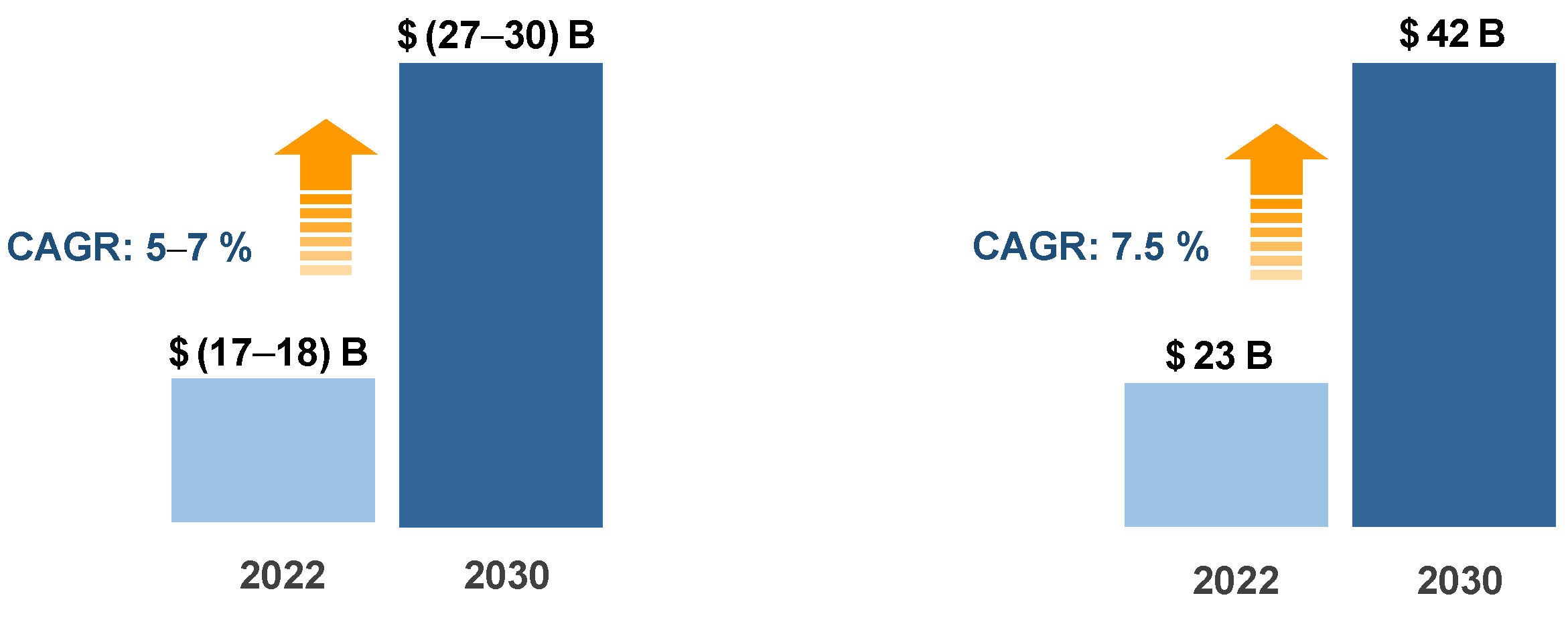
1.1. Market Size of AC Drives

AC drives and their control techniques are considered one of the important technologies in modern industry. According to the latest published reports, the global market size of AC drives accounted for an estimated value between USD 17 and 18 billion in 2022 at a compound annual growth rate between 5 and 7% [1,2]. The market size is expected to exceed USD 30 billion by 2030 [1].
In other published reports [3], the market size of AC drives is estimated to be USD 23 billion in 2022. It is projected to reach USD 42 billion by 2030, as shown in Figure 1. Therefore, the demand for AC drives is increasing and the investment in such technology looks feasible and promising.

1.2. History of DTC and Pioneer Contributors

In 1996, the ABB company announced on their website that they had reached the natural limit of AC motor torque control. They wrote: “We have reached the natural limit of motor torque response!” This was a breakthrough in the development of industrial AC drives.
Since that date, that DTC-based AC drive, designed and fabricated by ABB, was considered the first industrial AC drive that relied on the concept of the DTC technique [4]. However, the DTC technique’s history and roots return to the late 1980s. Specifically, between 1984 and 1986, the concept of DTC was proposed and invented by Takahashi and Noguchi, in their revolutionary paper [5,6].
Almost, at the same period, there was another innovative work carried out by Depenbrock [7,8]. The work is called direct self control instead of direct torque control. The main difference in both approaches is mainly considered in the trajectory of the motor flux vector. In DTC, the flux vector follows up a desired circular path. Meanwhile, in DSC, the flux trajectory has a hexagonal path [9]. The DSC with a hexagonal path of the stator flux vector results in a negative impact on the quality of the motor stator current due to the existence of undesired low-order harmonics.

1.3. Evolution toward High-Performance AC Drive

High-performance AC drives are motivated and driven by the desire to emulate the excellent performance of DC drives, such as the fast torque response and good speed accuracy, preserving, at the same time, the merits of AC motors, such as the rugged construction and the low maintenance requirements. As indicated in Figure 2, the armature current Ia and magnetic flux Φ (produced by the field current If) of a separately excited DC motor are orthogonal, i.e., they do not have a cross-coupling problem. This means they can be controlled independently. The decoupled characteristics of separately excited DC motors result in an excellent dynamic performance, including fast and accurate transient torque response.
Unfortunately, induction motors do not have that advantage. i.e., the flux-producing current Im and the torque-producing current Ir are coupled together, as shown in Figure 3.
If we classify the developed AC drives during several decades based on the control techniques, they can be categorized into three main categories: scalar control drives, vector control (VC) or field oriented control (FOC) drives, and direct torque control (DTC) drives.
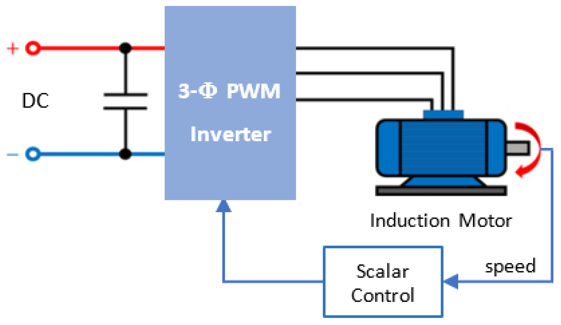
  • Scalar Control Drives:
In scalar control drives, the controlled variables are scalar quantities, such as stator voltage, stator frequency, or the ratio (V/F) [10]. Figure 4 illustrates a simplified block diagram of a scalar control AC drive.
Although scalar control methods are simple, they lead to poor transient performance and do not allow motor deployment in low-speed and very low-speed applications.
2.
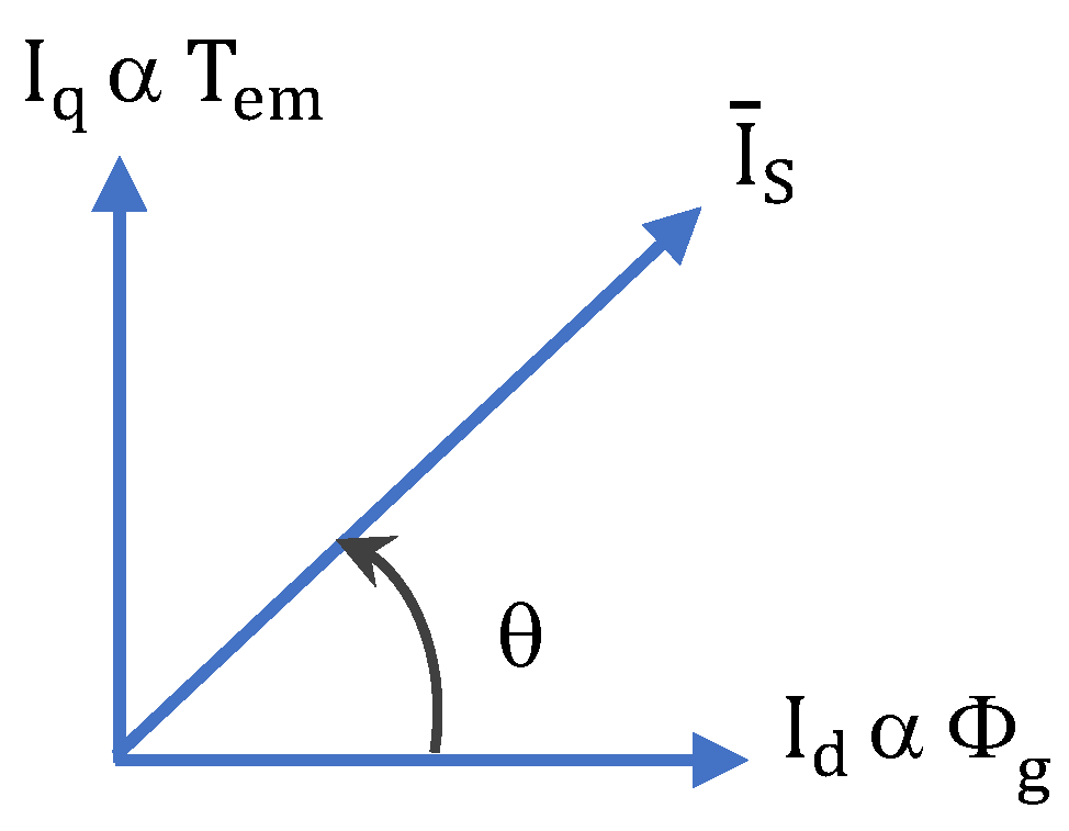
Vector Control (VC) or Field Oriented Control (FOC) Drives:
The limitations of scalar control techniques of AC drives have been overcome by applying the concept of FOC or VC. In fact, FOC or VC, which was originated and proposed by Blaschke in 1971 [11], was not spread or applied until 1980 due to the lack of high-speed processing capability during that period, which was required to implement the sophisticated control algorithms of the FOC. With the advancement in signal processing capabilities and microprocessor technologies during the 1980s, successful implementation of the VC has been achieved.
In VC, the stator current vector is decomposed into two orthogonal components: direct component Id and quadrature component Iq. The direct component Id is responsible for air gap flux production while the quadrature component Iq is responsible for electromagnetic torque production (See Figure 5). This way, the VC of the induction motor emulates the behavior of the DC motor [10], which results in good transient performance provided that the machine parameters are identified during the operation (Online identification).
3.
Direct Torque Control (DTC) Drives:
In DTC, both stator flux and electromagnetic torque produced by the motor are controlled directly by applying instantaneously the optimum inverter switching state that satisfies both flux and torque requirements [9,12]. Details about the DTC strategy are to be explained in the next section. The following table, Table 1, provides a quick comparison between the three categories.

2. Principles of the DTC Strategy Using a B6 Inverter

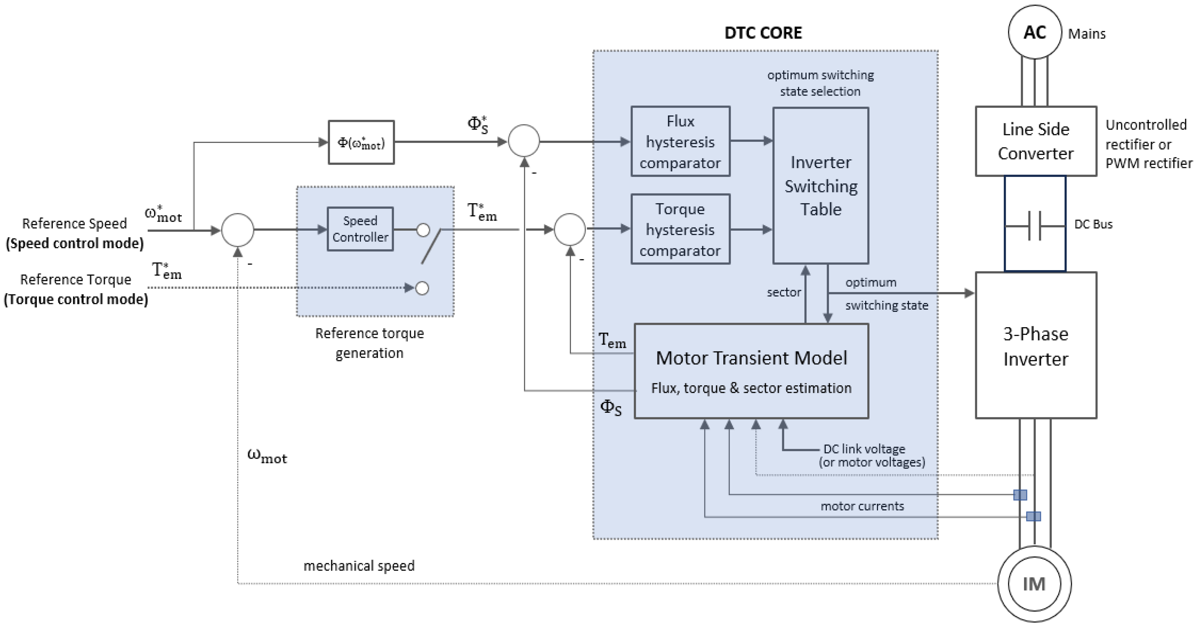
2.1. Block Diagram and Core Components of DTC

Owing to the block diagram shown in Figure 6, the core of the conventional DTC scheme of a three-phase induction motor is composed of the following blocks:
  • Motor transient model to compute the stator flux vector and electromagnetic torque;
  • Dual hysteresis on/off controllers: one for the flux and the other for the torque;
  • Optimum switching table whose output is the instantaneous values of the inverter switching state [13,14,15,16].
Figure 6. Block diagram of the conventional DTC system.
Vehicles 06 00043 g006
The DTC system can operate in two independent modes: torque control mode or speed control mode [17,18,19,20]. In torque control mode, the reference signal is the desired electromagnetic torque. Meanwhile, in speed control mode, the reference signal is the desired motor speed. The reference flux signal is a function of the motor reference speed. From zero speed to the rated speed, the flux is set to the rated value. For speeds higher than the rated value, the reference flux is reduced to verify the field weakening mode.
The system is incorporated with some Hall-effect transducers to measure motor terminal voltages and stator currents required for the computations of the motor transient model. The selection method of the optimum switching state is discussed in the next section.

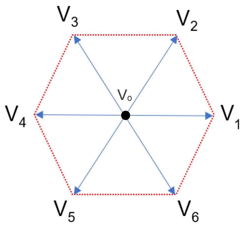
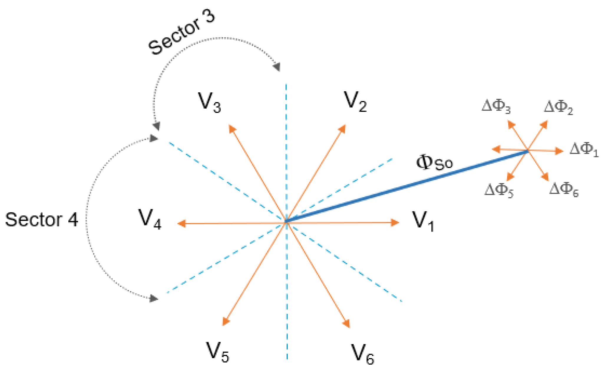
2.2. Space Vector Representation

The output voltage of the three-phase voltage source inverter can be represented by a vector called the voltage space vector using Equation (1):
V ¯ S = 2 3 V DC S 1 + e j 2 π / 3 S 3 + e j 4 π / 3 S 5
By solving this equation for all switching states, the equivalent voltage space vector components are obtained. Since there are eight switching states, the inverter can provide eight discrete vectors: six active vectors and two nil vectors or zero vectors [5,6]. Table 2 summarizes the discrete equivalent voltage space vector of three-phase VSI. The active vectors have equal magnitudes of two-thirds of the DC link voltage. They are displaced 60° electrically from each other. At the same time, the two nil vectors have zero magnitudes. The resultant discrete vectors have been sketched in Figure 7. These discrete vectors are used to control, simultaneously, both the torque and stator flux of the AC motor.

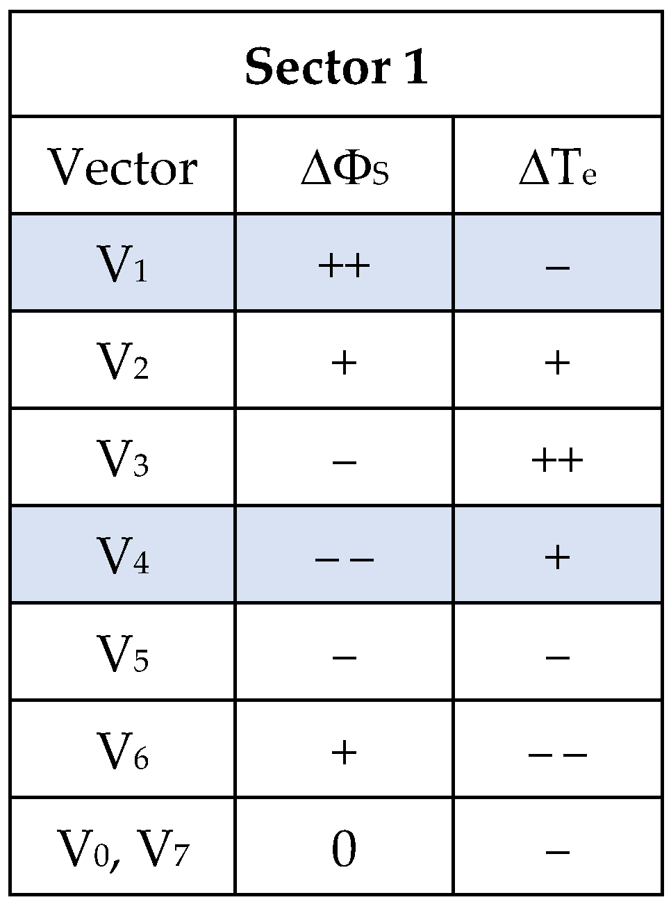
2.3. Control of the Stator Flux and Electromagnetic Torque

Assume that the stator flux vector lies in Sector One, as shown in Figure 8. Each inverter voltage vector has its effect on both torque and stator flux. e.g., if vector V1 is applied during the sampling period, the magnitude of the stator flux will increase. At the same time, the angle between the stator flux vector and the rotor flux vector will decrease rapidly, which results in a quick reduction in the magnitude of the developed torque. Remember that the electromagnetic torque is directly proportional to the SINE of the angle between the stator and rotor flux vectors.
If vector V4 is applied, the magnitude of the stator flux will decrease (See Figure 9). At the same time, the angle between the stator flux vector and rotor flux vector will increase rapidly, which results in a quick increment in the magnitude of the electromagnetic torque [17,18,19,20,21]. From these observations, we can develop an optimum switching table to control, simultaneously, both the torque and stator flux, which is the main objective of the DTC. Figure 10 summarizes the effects of all inverter voltage vectors on both torque and flux in Sector 1, where (++) means big increment, and (− −) means big decrement.
The ideal desired trajectory of the stator flux vector has a circular path. With DTC, the actual path is formed by applying, instantaneously, the most convenient inverter switching state. The optimum voltage vectors change from one sector to another, as illustrated in Figure 11. The blue circle represents the desired locus or the desired trajectory of the stator flux vector, while the two red dotted circles represent the upper and lower limits of the actual trajectory that should not be exceeded or deviated from.
Thus, in Sector One, for CCW rotation, vectors V2 and V3 should be mutually applied to follow the desired trajectory. In Sector Two, vectors V3 and V4 should be mutually applied to follow up the required locus. For CW rotation, vectors V1 and V6 should be mutually applied in Sector 2. Again, in Sector 1, vectors V5 and V6 should be mutually applied to keep track of the desired locus.

2.4. Machine Model Used with the DTC

The DTC technique requires online information about the stator flux vector (magnitude and angle) and electromagnetic torque. Therefore, firstly, we need to determine the stator voltage vector and stator current vector. Then, we can determine flux and torque.

2.4.1. Computation of Stator Voltage Vector

The stator voltage vector can be determined by any of the two given methods: either by direct measurement of the motor terminal voltage using three Hall-effect transducers (Equations (2)–(5)) or by computing the voltage vector with the aid of the inverter switching states and the online measurement of the DC link voltage using only one transducer (Equations (6)–(8)).
By direct measurements:
V ¯ S = 2 3 v a + e j 2 π / 3 v b + e j 4 π / 3 v c
V ¯ S = v α + j v β
v α = 1 3 2 v an v bn v cn
v β = 1 3 v bn v cn
where: e   j 2 π / 3 = 1 2 + j 3 2 and e   j 4 π / 3 = 1 2 j 3 2 .
By DC link voltage measurement and inverter switching states:
V ¯ S = 2 3 V DC S 1 + e j 2 π / 3 S 3 + e j 4 π / 3 S 5
v α = 1 3   V DC 2 S 1 S 3 S 5
v β = 1 3   V DC S 3 S 5
The first method is more accurate because it measures the voltages of the three-phases while the second method is more economical because it utilizes only one Hall-effect voltage transducer instead of three. Whatever the method, the (α–β) components of the stator voltage vector in the stationary reference frame should be determined by applying the park transformation.

2.4.2. Computation of Stator Current Vector

The stator current vector is also determined using a direct measurement of the stator phase currents using Hall-effect transducers. According to the given park transformation, the (α–β) components of the stator current vector are determined in the stationary reference frame owing to the following equations:
I ¯ S = 2 3 i a + e j 2 π / 3 i b + e j 4 π / 3 i c
I ¯ S = i α + j i β
i α = 1 3 2 i a i b i c
i α = i a
i β = 1 3 i b i c

2.4.3. Computation of Stator Flux Vector

After computing the stator voltage and current vectors components in (α–β) stationary reference frame, the corresponding stator flux vector is computed using Equations (14)–(17):
Φ ¯ S = 0 T S V ¯ S R S I ¯ S   dt
Φ ¯ S = α + j β
α = 0 T S v α R S   i α   dt
β = 0 T S v β R S   i β   dt
where TS is the sampling period.
Accordingly, the magnitude and the location of the stator flux vector are also calculated using Equations (18) and (19), respectively. They are considered inputs to the necessary DTC blocks, such as the hysteresis flux controller and the optimum switching table:
Φ S = α 2 + β 2
Ψ S = tan 1 β α

2.4.4. Computation of Electromagnetic Torque

The electromagnetic torque is computed using Equations (20) and (21), where P is the number of magnetic poles of the AC motor:
T em = 3 2   P 2 Φ ¯ S × I ¯ S
T em = 3 2   P 2 α i β β i α
For digital implementation, all previous equations are re-written or described in the discrete form, as given by Equations (22)–(26), to be handled with the data acquisition card. Since the DTC algorithm is not so complicated, a microcontroller-based system, or DSP, or any other type of PCI card can be employed as a digital platform to implement the overall DTC algorithm:
v α k = 1 3   V DC k 2 S 1 k S 3 k S 5 k =   v an k
v β k = 1 3   V DC k S 3 k S 5 k = 1 3 v bc k
α k + 1 = α k +   T S v α k R S   i α k
β k + 1 = β k +   T S v β k R S   i β k
T em k = 3 2   P 2 α k i β k β k i α k

3. Advantages and Drawbacks (Limitations) of DTC

Like any control technique, DTC provides some advantages and has some drawbacks or limitations.

3.1. Advantages of DTC

The major advantages of DTC can be summarized in the following points:
  • DTC provides quick torque and flux response [21];
  • With DTC, rated electromagnetic torque can be produced at zero speed;
  • It is based on a machine model with moderate complexity;
  • The DTC system can be implemented with conventional data acquisition cards;
  • The conventional algorithm of the DTC needs a few machine parameters;
  • Sensorless operation is possible with good accuracy.

3.2. Disadvantages and Limitations of DTC

The major disadvantages of DTC are addressed in the following points:
  • The conventional DTC scheme is not appropriate for servo applications [22];
  • For the low-speed range, the stator winding resistance should be identified (online estimated) to achieve high performance [23,24,25,26,27,28,29,30].
At very low speeds, the voltage drop across the stator winding constitutes a considerable part of the stator voltage [13,14,15,16]. Therefore, it cannot be ignored, especially if the machine is heavily loaded (fully loaded). Variations in the stator resistance occur due to changes in the winding temperature and the operating fundamental frequency of the motor-inverter set (AC drive) [24,28,30]. The error in stator resistance causes the actual values of motor variables to deviate from the corresponding reference values. Incorrect values of the stator resistance RS would result in errors in the computations of the stator flux vector (its magnitude and position). Accordingly, the computation of the electromagnetic torque will be negatively affected. Therefore, online identification of the stator resistance RS is a must for servo applications. Many stator resistance estimation techniques have been proposed to improve the performance of the DTC at a low-speed operation [23,24,25,26,27,28,29,30].

4. DTC Using a Four-Switch Inverter as a Non-Conventional Inverter Scheme

The DTC technique can be implemented using different inverter topologies. Some of the non-conventional topologies are the four-switch (B4) inverter, parallel resonant DC link inverter, and many other schemes, such as the multilevel inverter and matrix converter [31,32,33,34,35,36,37,38,39,40,41,42,43,44,45,46,47,48,49,50,51,52,53,54,55,56,57,58,59,60,61,62].
The non-conventional topologies would be deployed to achieve some benefits based on the operating power range: the four-switch inverter would be employed in the low power range to provide a low-cost AC drive. Meanwhile, in the medium power range, the parallel resonant DC link inverter provides a significant reduction in the switching power losses across the power transistors, resulting in an inverter operation at higher efficiency. Also, a multilevel inverter improves the steady state performance of the AC drive and reduces the power losses across the motor due to the high quality of the motor currents.

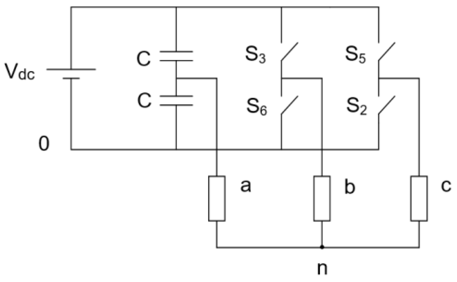
4.1. Operation of Four-Switch Inverter

This section presents the application of the DTC strategy using the four-switch three-phase inverter (FSTFI) or (B4) inverter. Firstly, a quick briefing about its operation is introduced. As shown in Figure 12, the (B4) inverter is composed of four switches forming two branches while the third branch is formed by two identical capacitors [31,35].
From the current point of view, for a balanced three-phase load, if the current in the second and third phases (ib and ic) are controlled to be sinusoidal with a phase shift of 120° electrically from each other, the current in the first phase (ia) that is fed through the capacitors will be forced to be sinusoidal as well, owing to the written equation:
i a + i b + i c = 0
i a = i b + i c
The main reasons for adopting the four-switch inverter topology (in a low power range):
  • Obligations to replace conventional (diode) rectifiers with modern PWM line side converters (LSC), shown in Figure 13, to satisfy the existing standards, such as IEC-61000-3-2 [63], IEC61000-3-4 [64], and IEC 61800-3:2004 [65].
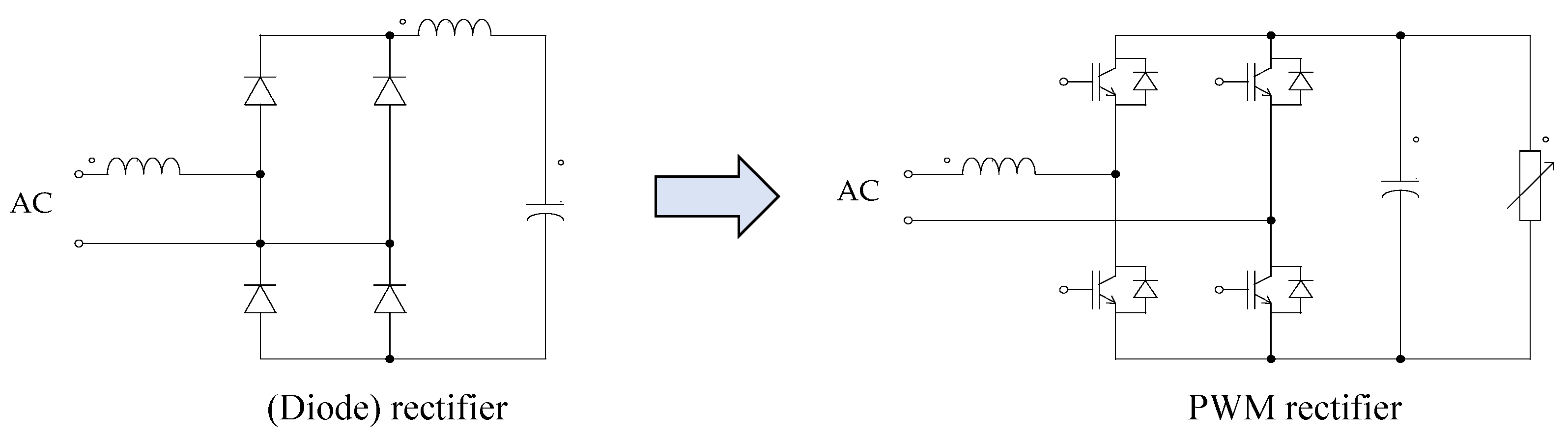
  • Since the incorporation of PWM LSC increases the overall cost of the drive, there is a desire to reduce the cost and achieve an economical AC drive with a satisfactory performance.

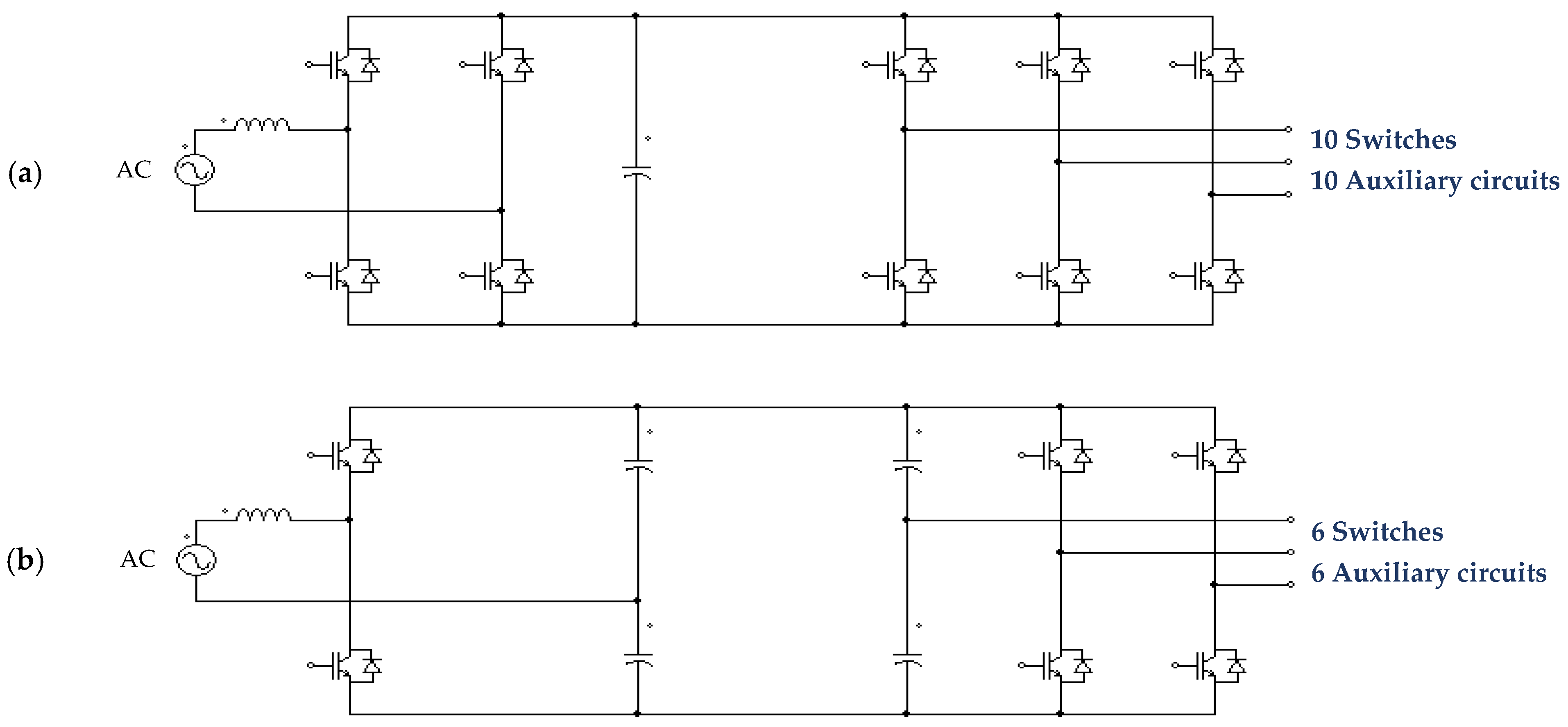
4.2. Possible Configurations of Low-Cost AC Drives

The cost of the AC drive can be reduced by utilizing the B4 topologies. Owing to Figure 14a, the system represents the front side converter and the motor side inverter with the full bridge scheme. In this case, ten power switches (transistors and anti-parallel diodes) are required to implement an AC drive with a single-phase modern PWM line side converter. Hence, the corresponding number of the required isolation circuits, driver circuits, and isolated power supplies is ten.
In Figure 14b, which is based on reduced switch count topologies, the number of needed power switches is dramatically reduced from ten devices to only six devices. In addition to that, the corresponding number of the needed isolation circuits, driver circuits, and isolated power supplies is also reduced from ten to six circuits. Thus, there is a saving of 40% in the number of power switches and the corresponding auxiliary electronic circuits.
Accordingly, FSTPI integrated with the 1-Φ active rectifier (PWM line side converter with unity PF operation) shown in Figure 15a offers a reduction in switch count from ten to six power switches, which results in a reduction of 40% in the number of power transistors and their auxiliary circuits.
In addition, FSTPI integrated with a three-phase active rectifier (PWM line side converter with unity PF operation) offers a reduction in switch count from twelve to eight switches, which results in a reduction of 33% in power transistors and their auxiliary circuits. Thus, if the AC drive is to be fed from a three-phase supply instead of a single-phase supply, the total reduction in the power devices and the corresponding auxiliary circuits will be 33%, as shown in Figure 15b, which is also good provided that the performance of the AC drive is satisfactory.
Since the DC link voltage with the conventional diode rectifiers should be filtered with smoothing capacitors, the utilization of capacitors in the front side rectifier and the motor side inverter does not significantly deteriorate the achieved reduction in the cost of the AC drive.

4.3. Space Vector Representation of the Four-Switch Inverter

The voltage space vector of the four-switch 3-Φ inverter is computed using Equation (29):
V ¯ S = 2 3 V DC 0.5 + e j 2 π / 3 S 3 + e j 4 π / 3 S 5
If the previous equation is resolved in the (α–β) system of coordinates, the following components in the stationary reference frame are obtained:
v α =   V DC 3 1 S 3 S 5
v β =   v bc 3 =   V DC 3 S 3 S 5
Since the inverter is composed of four switches, only four switching states are available. After applying the park transformation of Equation (29) to the inverter output voltage, the following facts are obtained:
  • The inverter provides only four active vectors [32,33];
  • The vectors are not equal; they have different magnitudes;
  • The vectors are displaced 90° electrically from each other [34];
  • The inverter does not provide any zero/nil vectors [33,35].
The resultant discrete voltage space vector is illustrated in Figure 16. The challenge is how to implement the DTC strategy with only four unequal active vectors; meanwhile, the zero vectors do not exist [31,32,33,34,35].

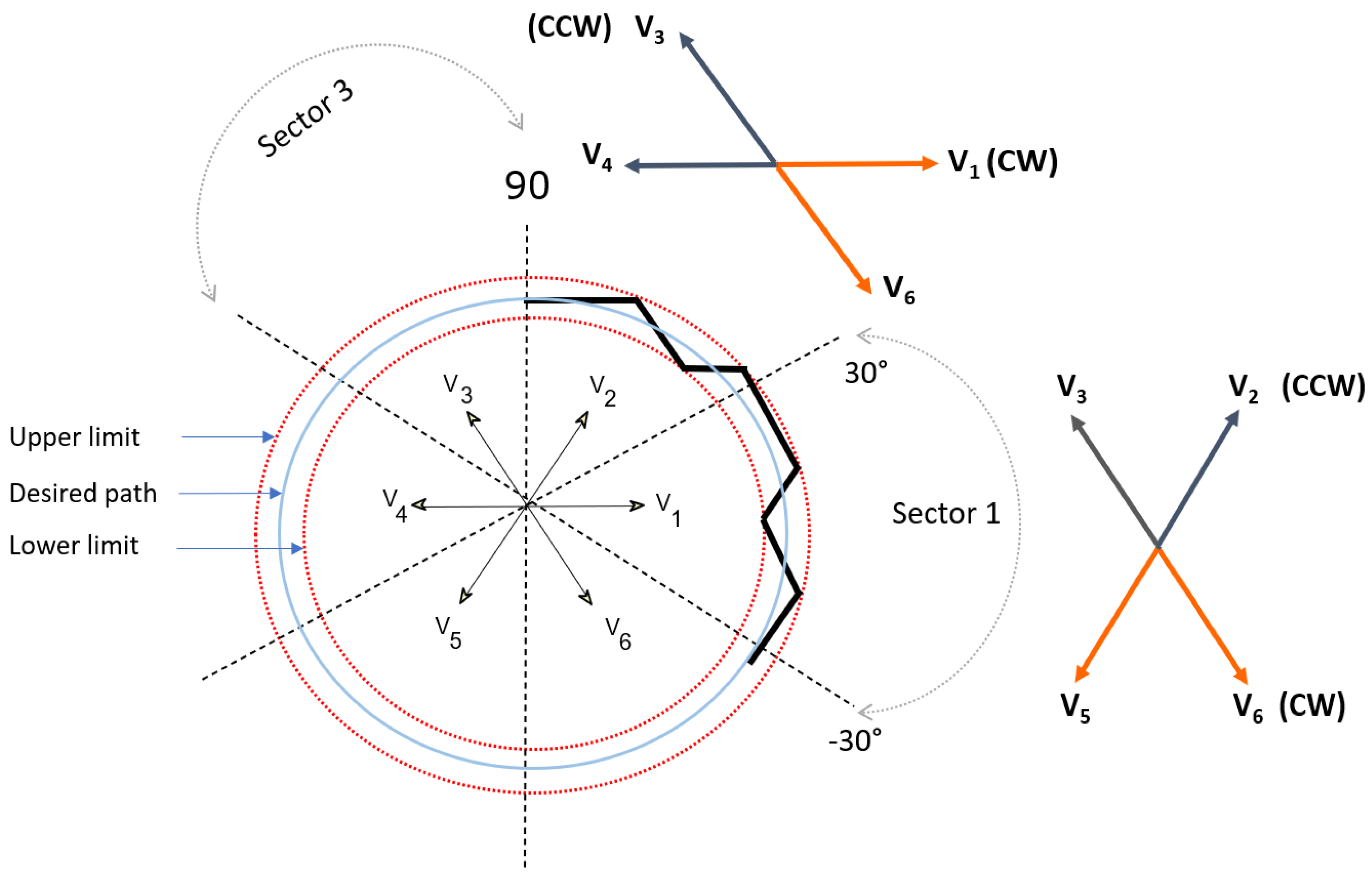
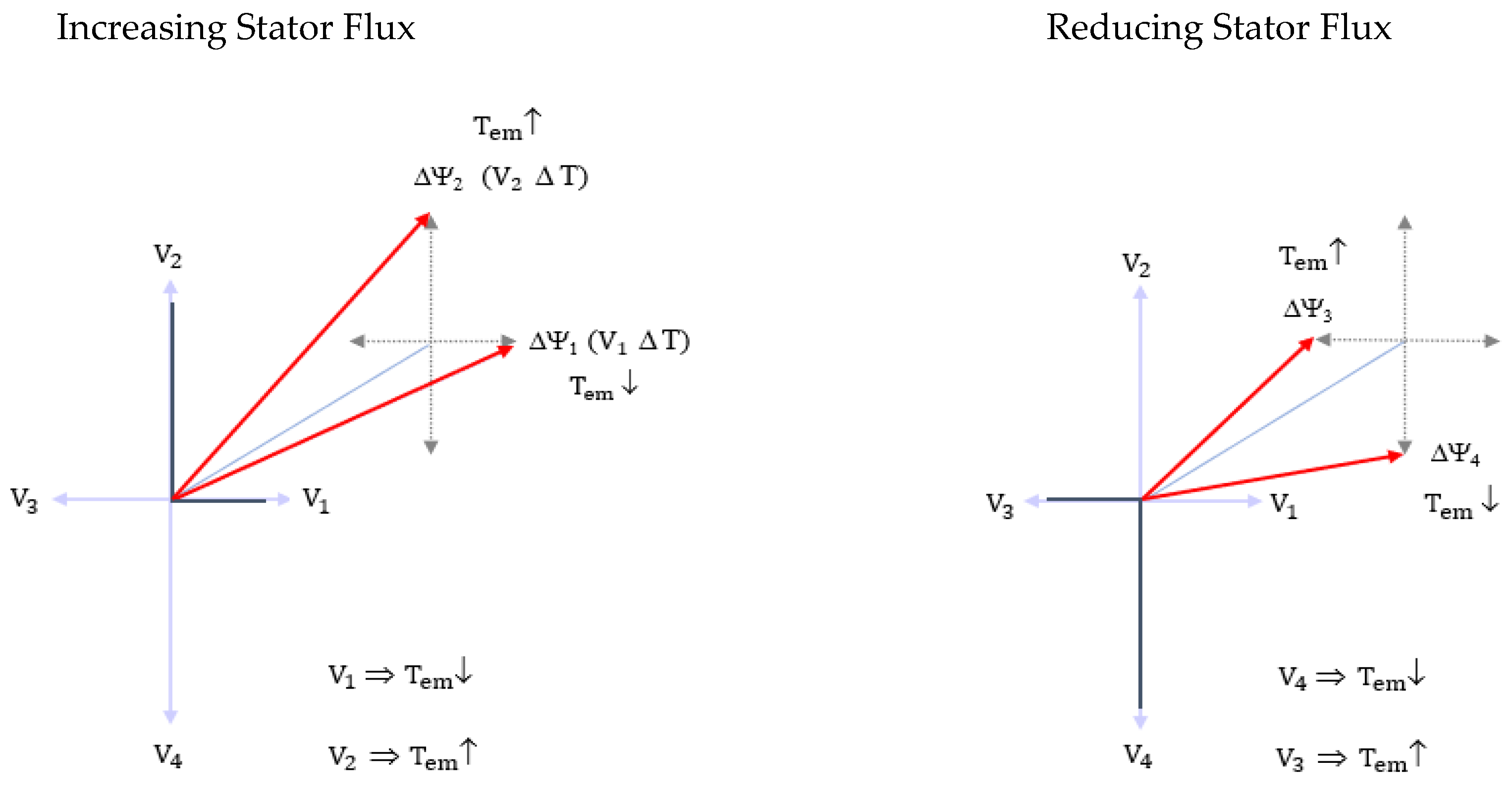
4.4. Principles of Flux and Torque Control with the Four-Switch Inverter

With the four-switch inverter, four distinct sectors exist instead of six. According to the left-hand-side graph of Figure 17, assume that the stator flux vector is initially in Sector 1. To increase the magnitude of the stator flux, whether vector V1 or vector V2 can be applied, depends on the torque requirement, as explained below: if the torque is to be reduced, vector V1 must be applied during the sampling period. Meanwhile, if the torque is to be increased, V2 must be applied. On the other hand, if the stator flux vector is still located in Sector 1, to reduce its magnitude, two options exist: applying V4 or V3 owing to the torque requirement, as indicated in the right-hand side graph of Figure 17. To reduce both the flux and the electromagnetic torque, vector V4 must be applied. Meanwhile applying vector V3 results in a quick increment in the electromagnetic torque.
Owing to the left-hand-side graph of Figure 18, to increase the magnitude of the stator flux in Sector 2, vectors V2 or V3 can be applied based on the torque requirement. By applying V2, the torque is reduced. Meanwhile, applying V3 increases the torque. Conversely, look at the right-hand-side graph of Figure 18. To reduce the magnitude of the stator flux, two options exist: applying vectors V1 or V4. The selection is based on the torque requirement, as follows: to reduce the torque, apply vector V1. To increase the torque, apply vector V4.
This way, the DTC system can be studied in all remaining sectors to determine the optimum switching state that can satisfy instantaneously both flux and torque requirements. The optimum switching states in each sector are summarized in Table 3.
The resultant trajectory of the stator flux vector under the DTC technique with a B4 inverter is illustrated in Figure 19. The flux locus has a square path formed by the four active vectors [34]. By reducing the hysteresis band of the flux controller, the locus will have a relatively small deviation from the desired circular path. The actual trajectory is restricted by the upper and lower limits, as shown in Figure 19.

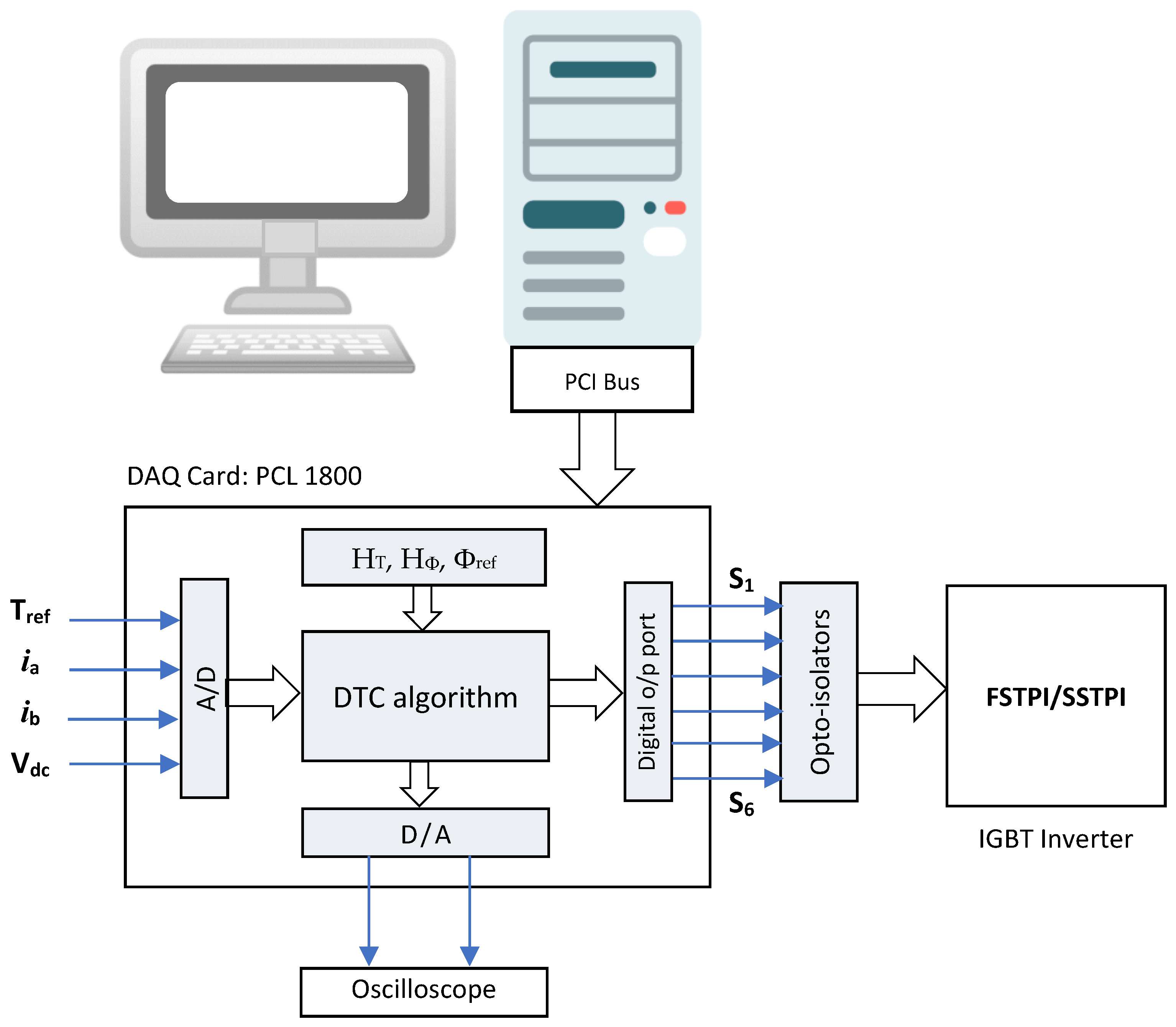
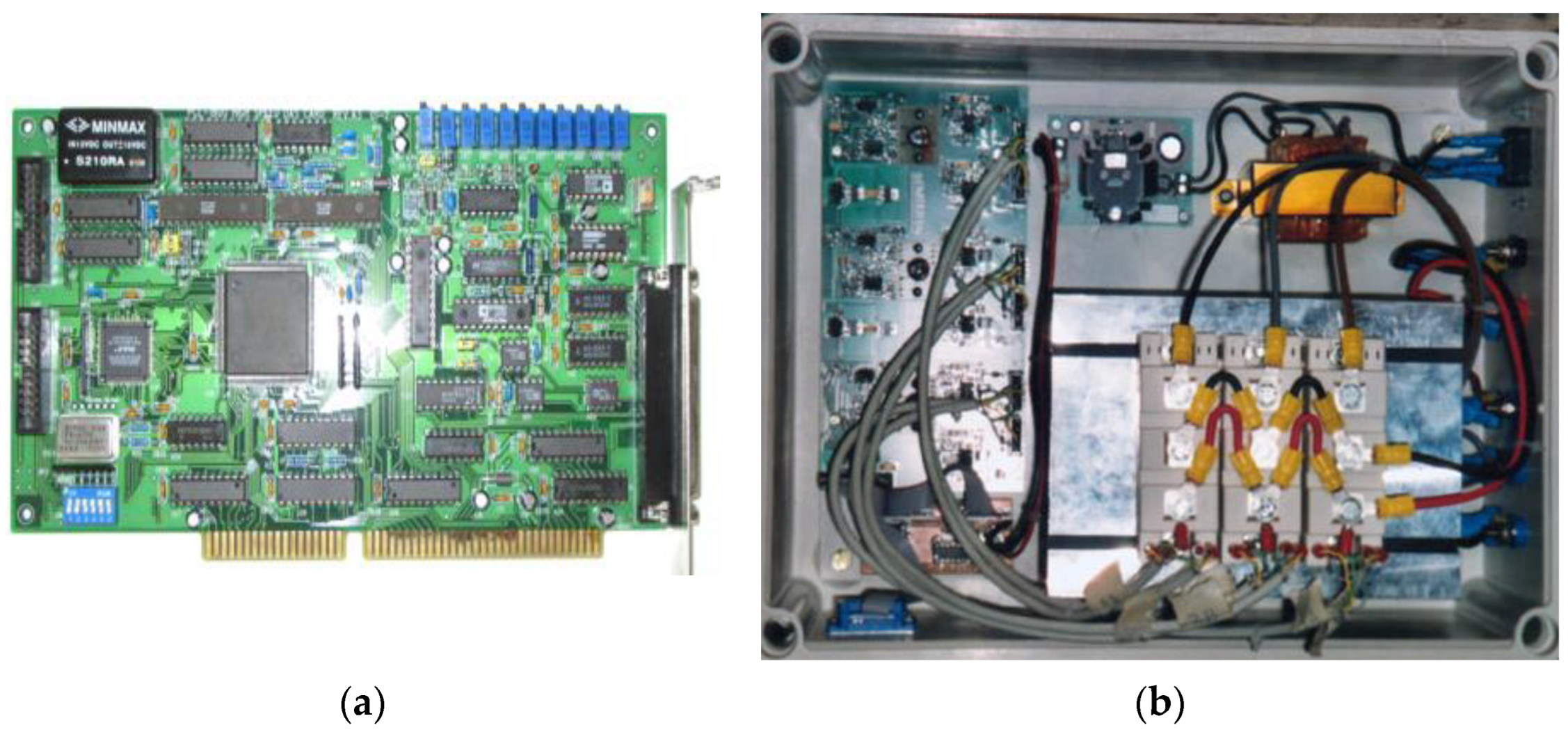
5. Experimental Setup

The experimental prototype, illustrated in Figure 20, is composed of the following items:
Three-phase IGBT inverter (with an open control feature) is constructed with all necessary auxiliary circuits (isolation, drive, over-current protection, and short circuit protection). One inverter leg can be disabled and substituted by two identical capacitors (1200 μF) to select between FSTPI and SSTPI topologies;
A data acquisition card PCL-1800 (using C code) is used to carry out all software routines of the DTC algorithm. The parameters of the IM (stator resistance and number of poles) and the set point of the stator flux are plugged into the program. They can be modified according to the motor rating. The reference electromagnetic torque is an external analog input to the data acquisition card;
Two Hall-effect current transducers are utilized to measure the motor phase currents;
A Hall-effect voltage transducer is employed to measure the DC link voltage to calculate the orthogonal components of the stator voltage vector (Vα and Vβ).
Some photos of the experimental prototype are illustrated in Figure 21.
Parameters of the experimental system is given in Appendix A.
Figure 20. Block diagram of the experimental test rig of the investigated DTC systems.
Vehicles 06 00043 g020
Figure 21. Some photos of the employed units: (a) DAQ card PCL 1800; (b) Hardware circuits of the IGBT Inverter.
Vehicles 06 00043 g021

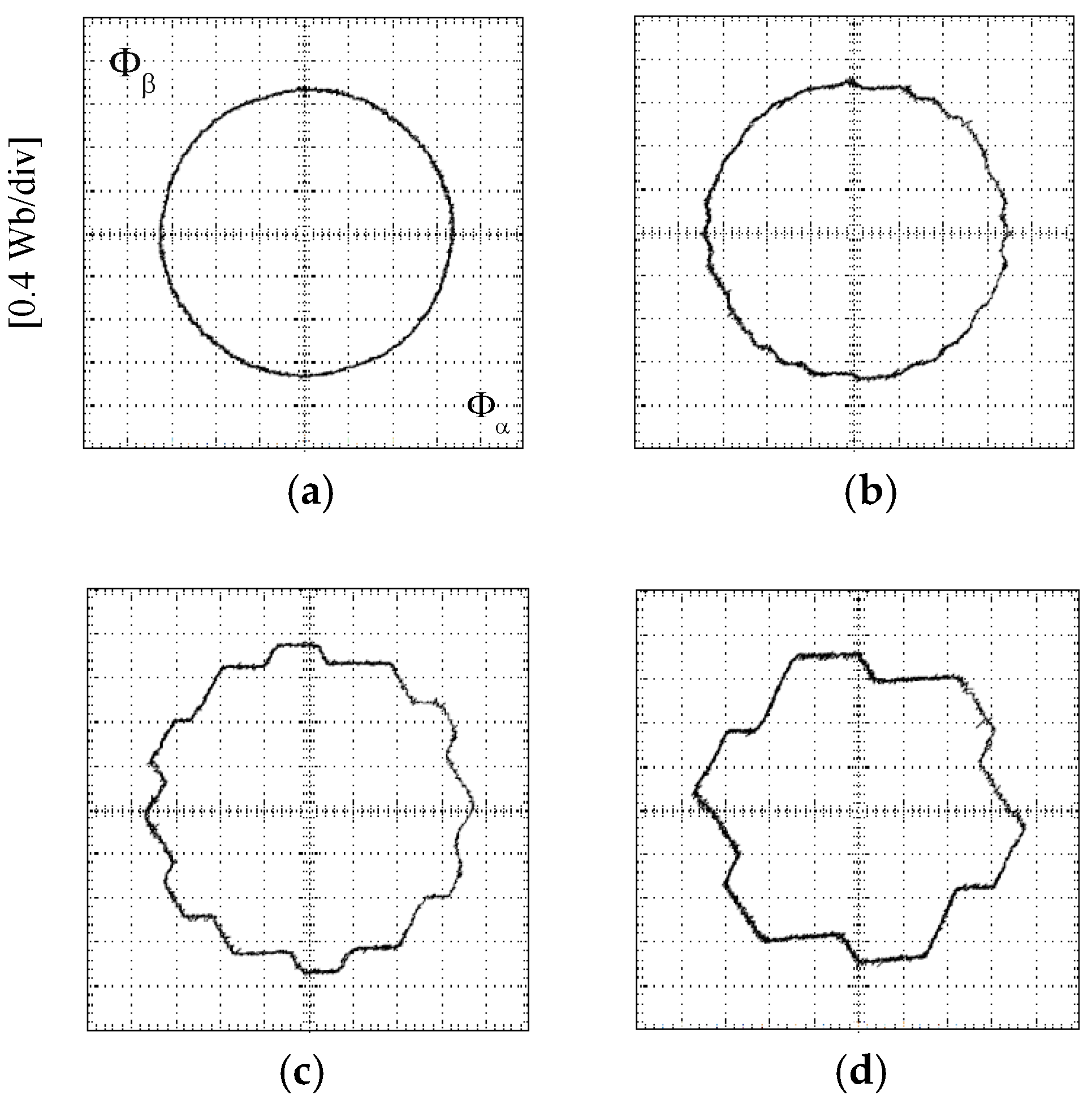
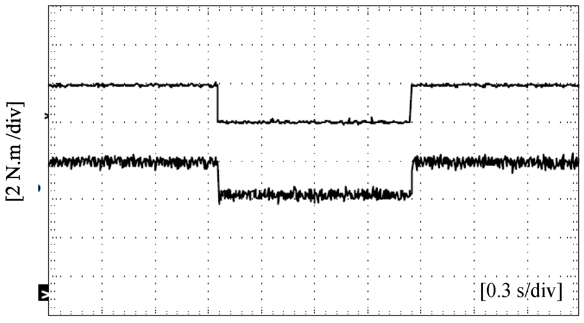
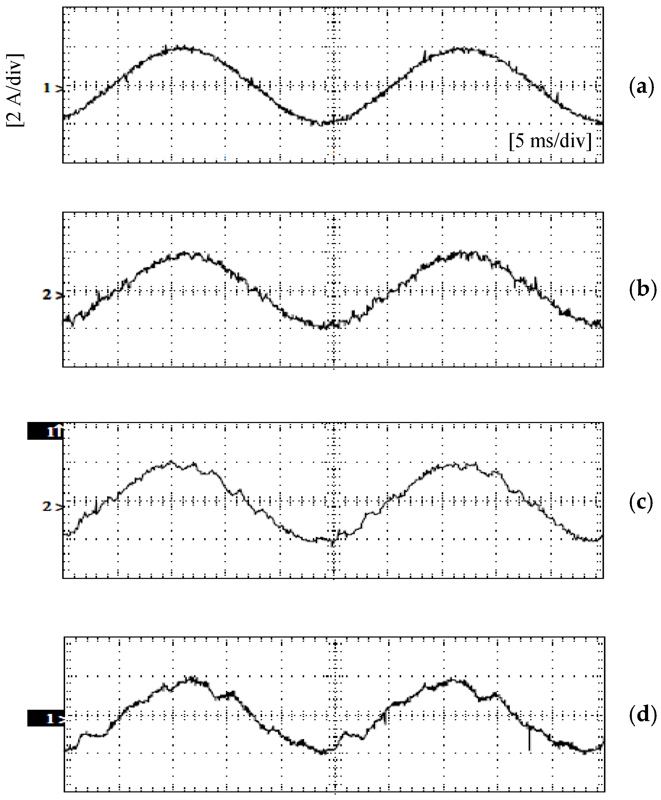
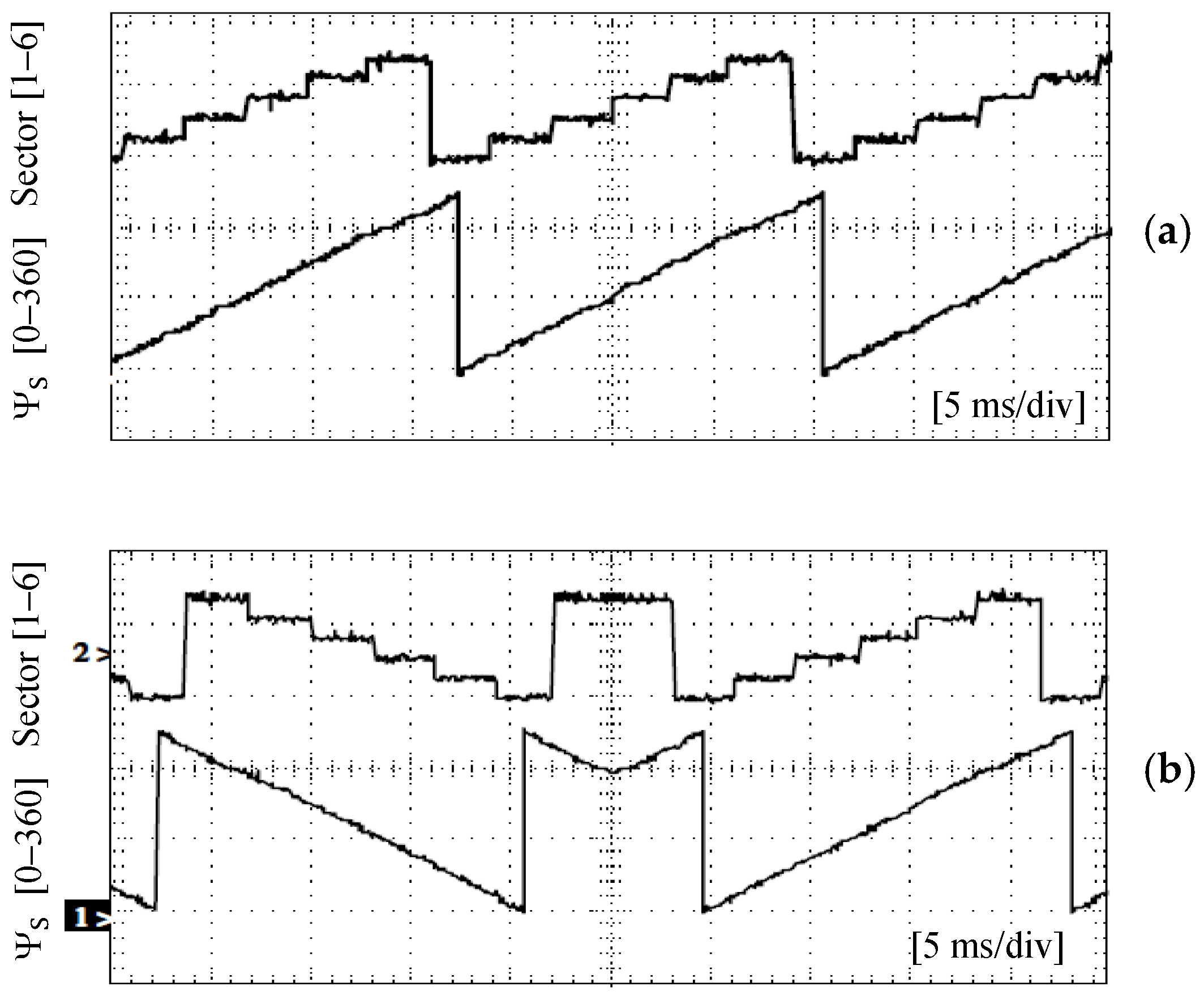
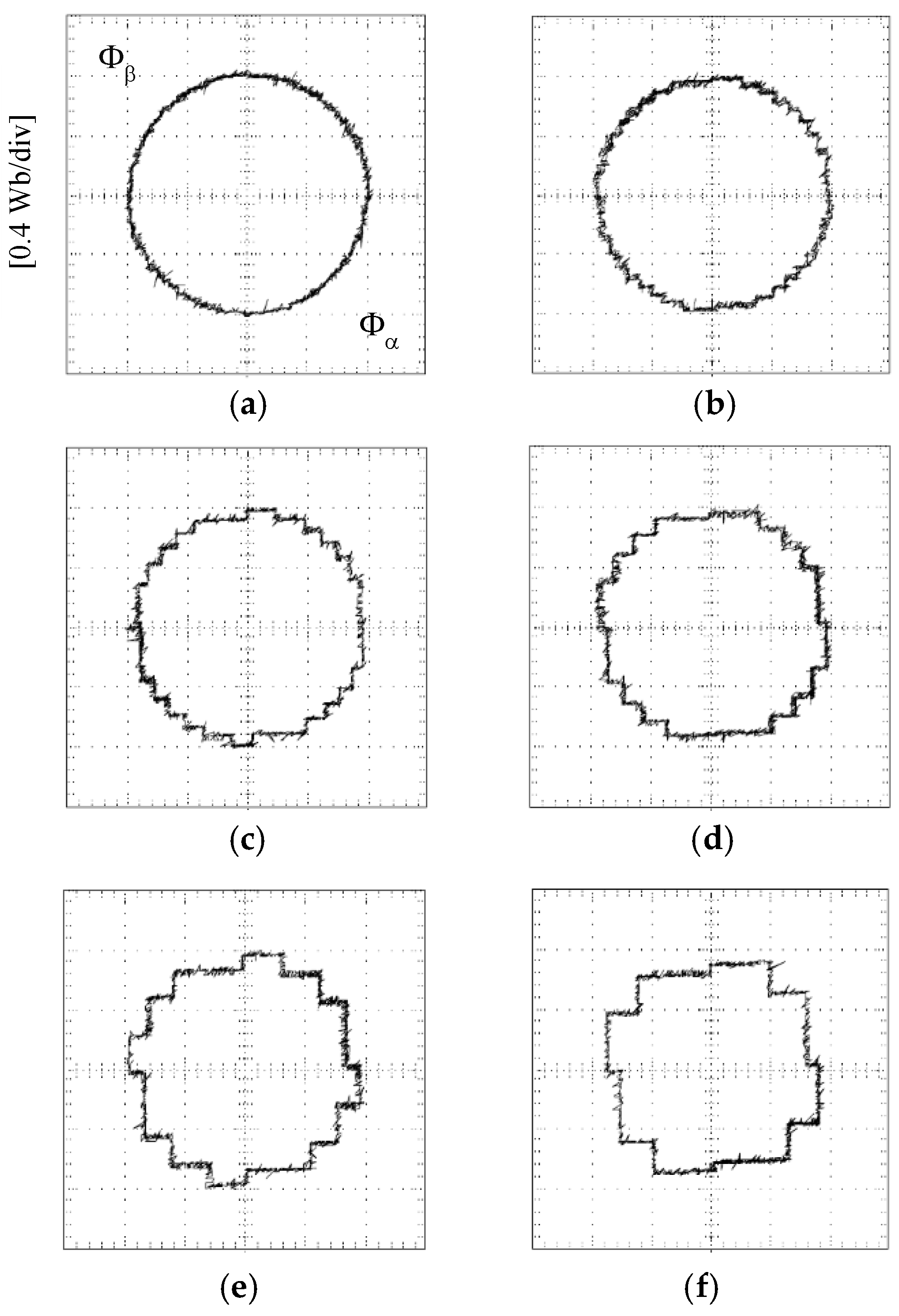
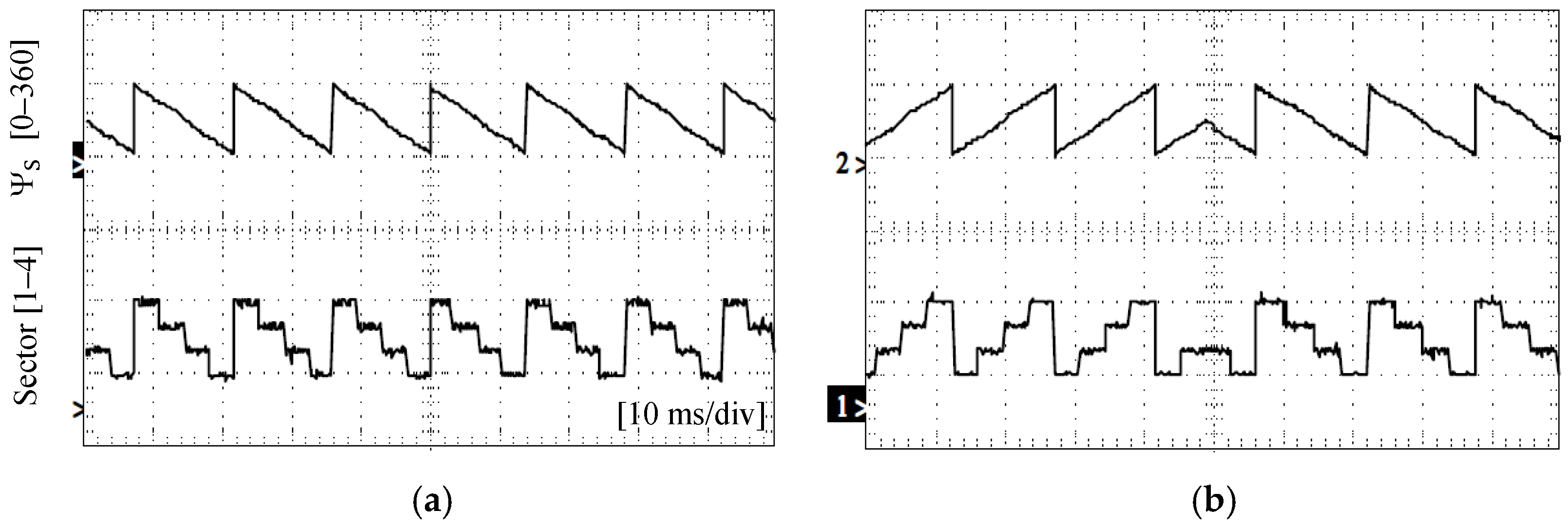
6. Experimental Results of the Investigated DTC Systems

The presented results are divided into two main groups: DTC results obtained by the SSTPI (B6) inverter (results shown in Section 6.1) and DTC results obtained by the FSTPI (B4) inverter (results shown in Section 6.2). A qualitative comparison of both systems is presented in Section 6.3.

6.1. Experimental Results of the DTC System Using a B6 Inverter

In this section, some experimental results of the implemented DTC system using a conventional six-switch (B6) inverter are presented. Steady-state stator flux vectors are plotted at different values of the hysteresis band of the flux controller (0%, 5%, 10%, and 20%), as depicted in Figure 22. It can be observed that the locus of the stator flux vector is improved and approaches to be circular as the hysteresis band is reduced from 20% down to 0%. The discrete voltage vectors of the B6 inverter can be observed clearly when the hysteresis band is relatively big (20% and 10%).
The electromagnetic torque response is plotted in Figure 23. The reference value is ±1 N.m. The hysteresis band of the torque controller is set to 0% while the hysteresis band of the flux controller is set to 0% as well.
The steady-state stator currents are plotted in Figure 24 at different values of the flux hysteresis band. The torque hysteresis band is set to zero. According to the obtained results, the stator current waveform is improved as the flux tolerance band is reduced from 20% to 0%. The quality of the stator current waveform is improved as the hysteresis band of the flux controller is reduced.
In addition, the flux angle Ψ S (0°–360°) and the corresponding sector (1–6) are plotted for different operating conditions: steady-state CCW rotation (as depicted in Figure 25a) and transient change from CW to CCW rotation (as depicted in Figure 25b).

6.2. Experimental Results of DTC Using a B4 Inverter

Some experimental results of the implemented DTC technique using the four-switch inverter are presented in this section. In Figure 26, the steady-state flux trajectory has been plotted at different values of the flux controller hysteresis band between 0% and 20%. The results indicate that the trajectory of the stator flux vector deviates from the circular path as the hysteresis band increases from 0% to 20%. The four discrete active vectors of the four-switch inverters can be easily identified when the tolerance bands of the flux controller are set to the values 10%, 15%, and 20%.
Figure 27 illustrates the electromagnetic torque response with the DTC using a B4 inverter, where the tolerance band of both hysteresis controllers is set to 0%. The reference torque is set to ±1 N.m.
The steady-state stator currents of Phase a, which is fed from the two capacitors, are plotted in Figure 28 at different values of the flux hysteresis band. According to the obtained results, the stator current waveform is improved as the flux tolerance band is reduced from 20% to 0%.
The flux angle Ψ S (0°–360°) and the corresponding sector (1–4) are plotted for different operating conditions: steady-state CW rotation (as shown in Figure 29a) and transient change from CCW to CW rotation (as shown in Figure 29b).
Moreover, the transient response of the stator flux is plotted in Figure 30 at different values of the hysteresis band of the flux controller. Meanwhile, the hysteresis band of the torque controller is set to 0%. The magnitude of the reference flux |ΦS| is 0.8 Wb.
According to the obtained results, the DTC strategy with the four-switch (B4) inverter results in a settling time of 7 ms, approximately, which is considered fast enough in high-performance AC drives. The results indicate, also, the capability of the flux controller to restrict the actual stator flux within the predetermined value of the flux hysteresis band.

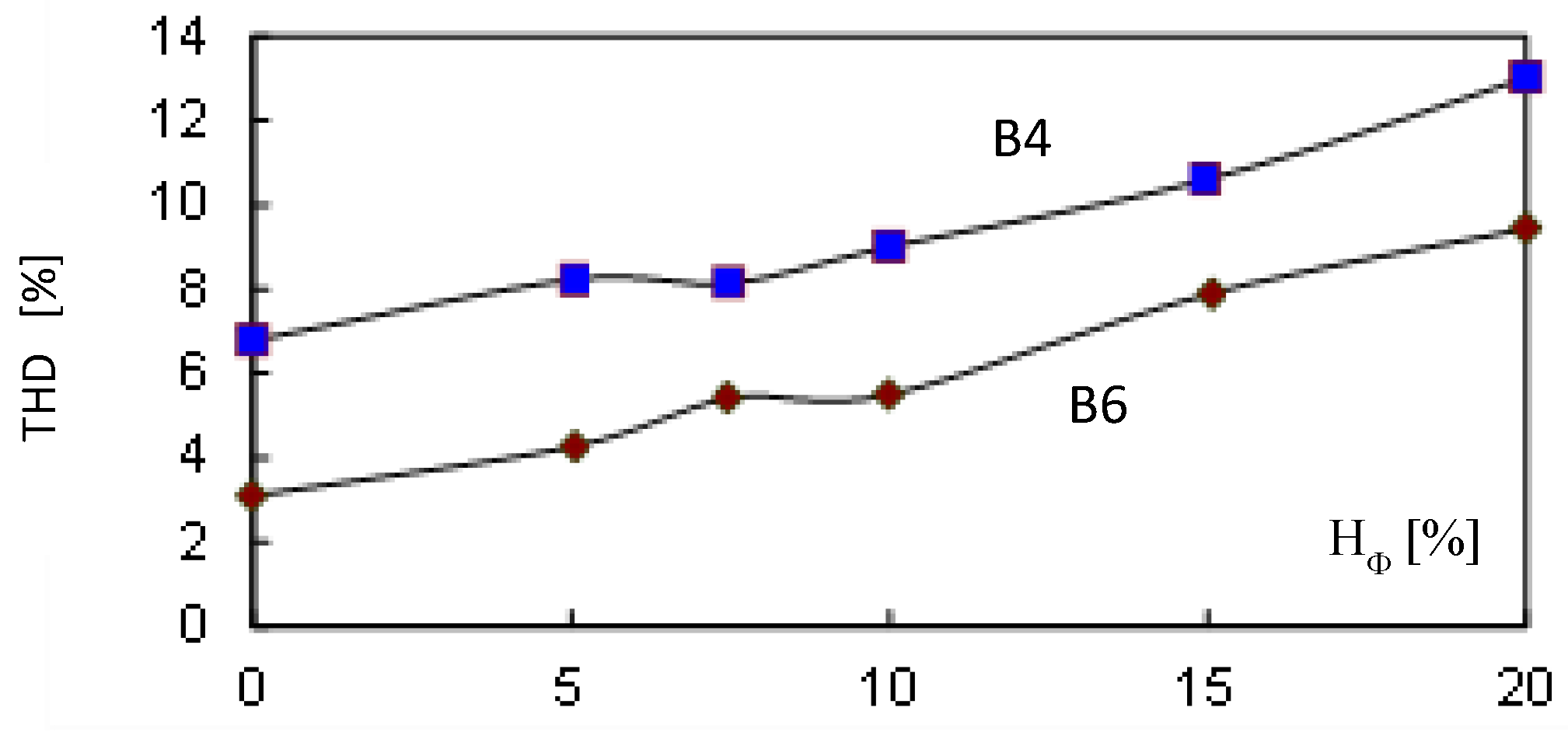
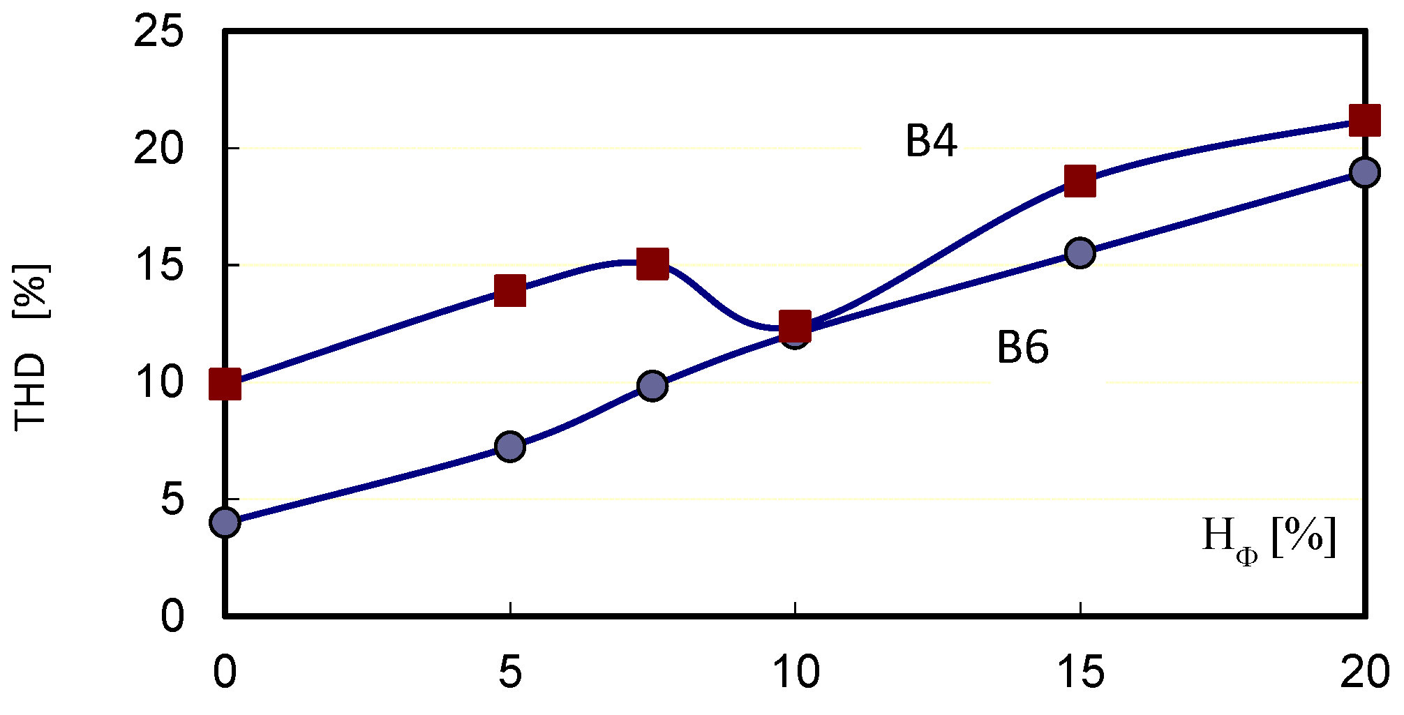
6.3. Quantitative Comparison between Both DTC Systems

The experimental results previously presented in Section 6.1 and Section 6.2 can be used to make a comparison between both DTC systems from a quality point of view (qualitative analysis). In this section, some results of the carried out quantitative analysis are presented to compare both DTC systems implemented using B6 and B4 inverter topologies.
In Figure 31, the THD of the stator flux with both DTC systems is plotted for different values of the flux hysteresis band from 0% to 20%. With the B4 inverter, the THD of the stator flux waveforms is between 7% and 13% approximately. Meanwhile, with the B6 inverter, the corresponding values of the THD of the stator flux are between 3% and 9%.
In Figure 32, the THD of the stator current with both DTC systems is plotted for the same values of the flux hysteresis band from 0% to 20%. With the B4 inverter, the THD of the stator current is between 10% and 21%, approximately. Meanwhile, with the B6 inverter, the corresponding values of the THD of the stator current are between 4% and 19%.
The obtained results indicate that the DTC with the SSTPI (B6) inverter provides lower THDs for the entire range. This means, the B6 inverter still provides superior performance, owing to the extra inverter switching states.

7. Conclusions

Although DTC has been invented for a long time to control the operation of induction motors to achieve quick response, it is still one of the proven and applicable technologies in the modern industry.
One of the state-of-the-art topics in DTC systems is the utilization of several topologies of power electronic converters, such as the reduced switch count (four-switch) inverters in low-power applications to achieve an economical AC drive with satisfactory transient and steady-state performance. This paper has investigated and addressed the utilization of a four-switch inverter to develop a low-cost DTC drive with satisfactory performance during both transient and steady states.
The optimum switching table of the DTC-based four-switch inverter has been derived owing to the main concepts of flux and torque control. An experimental prototype has been developed to verify the investigated scheme. The DTC core and its computational blocks have been implemented using a low-cost data acquisition card, PCL 1800, which is connected to the PC using a PCI bus. The system has been investigated under different operating conditions.
The experimental results of the DTC system using the four-switch (B4) inverter indicate the fast response of the stator flux under step change from 0.0 to 0.8 Wb. The response time is 7 ms approximately.
Owing to the obtained experimental results, when the flux hysteresis band is changed between 0% and 20%, the resultant total harmonic distortion (THD) of the stator flux waveform is between 7% and 13% in the case of the four-switch (B4) inverter. Meanwhile, the corresponding value of the THD achieved with the six-switch (B6) inverter is between 3% and 9%.
Moreover, the resultant THD of the stator current waveform is between 10% and 21% in the case of the four-switch (B4) inverter. Meanwhile, at the same operating conditions, the THD of the stator current with the six-switch (B6) inverter is between 4% and 19%.
Accordingly, the proposed DTC drive using the four-switch (B4) inverter is valid and applicable to develop a high-performance AC drive at moderate costs.
In terms of cost reduction and saving, the proposed DTC drive using the four-switch inverter provides a saving of 33% in the number of the utilized power transistors (four IGBTs are used instead of six). Consequently, the number of required auxiliary circuits (galvanic isolation, driving, snubber, and isolated power supplies) is also reduced by 33%. Therefore, there is a saving of 30%, at least in the initial cost of the overall AC drive.
Consequently, the reduced switch count topology (B4-based DTC drive) is feasible and competitive in low-power applications when cost reduction is of major concern.

Funding

This research received no external funding.

Data Availability Statement

Data are contained within the article.

Conflicts of Interest

The author declares no conflicts of interest.

Abbreviations

BLDCBrushless DC motor
CCWCounterclockwise
CWClockwise
DTCDirect torque control
DSPDigital signal processor
FOField orientation
FPGAField programmable gate array
FSTPIFour-switch three-phase inverter
THDTotal harmonic distortion
SSTPISix-switch three-phase inverter
HILHardware in the loop
IMInduction motor
EVElectric vehicle
MPCModel predictive control
PCPersonal computer
PCIPeripheral component interconnect
PMPermanent magnet
PWMPulse width modulation
RISCReduced instruction set computer
SCScalar control
SRMSwitched reluctance motor
SVMSpace vector modulation
VCVector control
VSIVoltage source inverter
Symbols
VaArmature voltage of a separately excited DC motor (V)
VfField voltage of a separately excited DC motor (V)
IaArmature current of a separately excited DC motor (A)
IfField current of separately excited DC motor (A)
ΦMagnetic flux of separately excited DC motor (Wb)
T em * Reference value of electromagnetic torque (Nm)
TemActual electromagnetic torque (Nm)
I S 
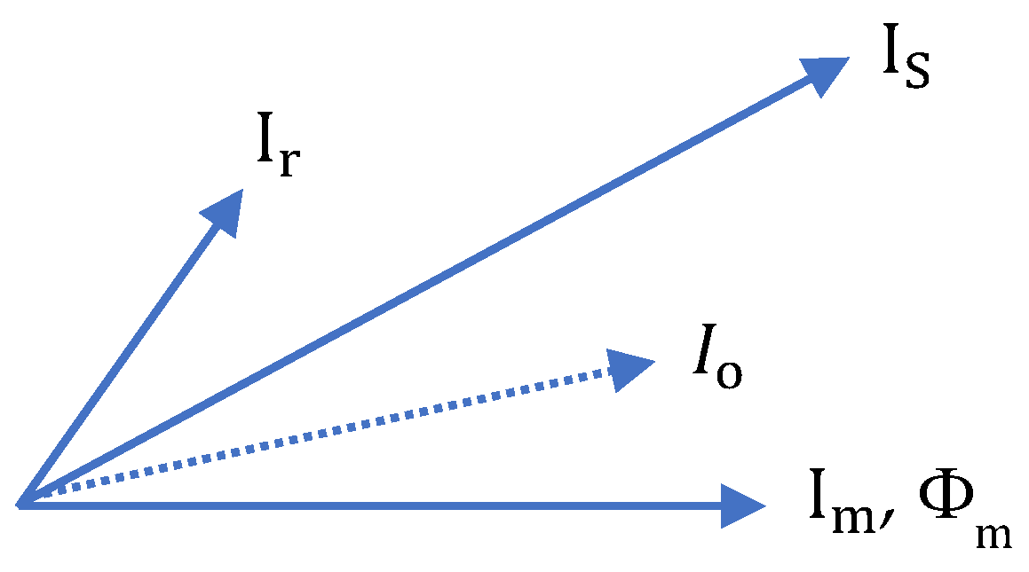
Stator current of three-phase induction motor (A)
I r Rotor current of three-phase induction motor (A)
I o Magnetizing current of three-phase induction motor (A)
Φ g Airgap flux of three-phase induction motor (Wb)
Φ ¯ S Stator flux vector (Wb)
Φ α , Φ β Stator flux components in the stationary reference frame (Wb)
Id, IqDirect and Quadrature components of stator current (A)
V ¯ S Stator voltage space vector (V)
S1, S3, S5Switching states of the inverter power transistors
V1 → V6Discrete stator voltage space vector
VDCDC link voltage of the VSI (V)
v α , v β Instantaneous values of stator voltage components in stationary reference frame (V)
i α , i β Instantaneous values of stator current components in stationary reference frame (A)
HΦHysteresis band of flux controller (%)
HTHysteresis band of torque controller (%)
Ψ S Instantaneous flux angle of stator flux vector (deg or rad)
ΔΦSError between reference and actual stator flux (Wb)
ΔTeError between reference and actual electromagnetic torque (Nm)
ω mot * Reference motor speed (rpm)
ω mot Actual motor speed (rpm)

Appendix A

Table A1. Parameters of the experimental system.
Electric Machine
Typesquirrel cage IM
Power rating1.35 kW
P4 poles
Rs4.59 Ω
Rr3.95 Ω
Lm0.443 H
Ls0.613 H
Lr0.464 H
Hall-effect current transducersLA 55P
Hall-effect voltage transducersLV 25P
Capacitors (C) of B4 inverter2 × 1 mF

References

  1. AC Drives Market Report by Components (Electrical Supply, Motor, Process Interface), Voltage (Low Voltage, Medium Voltage), Power Rating, Size, Application, Industry—Global Forecast 2023–2030. Available online: https://www.360iresearch.com/library/intelligence/ac-drives (accessed on 1 December 2023).
  2. Global AC Drives Industry Research Report, Growth Trends and Competitive Analysis 2022–2028. Available online: https://www.360researchreports.com/global-ac-drives-industry-21727719 (accessed on 1 September 2023).
  3. AC Drive Market Report. Available online: https://introspectivemarketresearch.com/reports/ac-drives-market/ (accessed on 1 September 2023).
  4. Tiitinen, P.; Surandra, M. The next generation motor control method, DTC direct torque control. In Proceedings of the International Conference on Power Electronics, Drives and Energy Systems for Industrial Growth, New Delhi, India, 8–11 January 1996; Volume 1, pp. 37–43. [Google Scholar] [CrossRef]
  5. Takahashi, I.; Noguchi, T. A New Quick-Response and High-Efficiency Control Strategy of an Induction Motor. IEEE Trans. Ind. Appl. 1986, 22, 820–827. [Google Scholar] [CrossRef]
  6. Noguchi, T.; Takahashi, I. Quick torque response control of an induction motor based on a new concept. In Proceedings of the IEEJ Technical Meeting on Rotating Machine RM84-76, Japan, September 1984; pp. 61–70. [Google Scholar]
  7. Depenbrock, M. Direct self-control (DSC) of inverter-fed induction machine. IEEE Trans. Power Electron. 1988, 3, 420–429. [Google Scholar] [CrossRef]
  8. Depenbrock, M. Direkte selbstregelung (DSR) für hochdynamische drehfeldantriebe mitstromrich terspeisung. etz-Archiv 1985, 7, 211–218. [Google Scholar]
  9. Kumar, R.H.; Iqbal, A.; Lenin, N.C. Review of recent advancements of direct torque control in induction motor drives—A decade of progress. IET Power Electron. 2018, 11, 1–15. [Google Scholar] [CrossRef]
  10. El Ouanjli, N.; Derouich, A.; El Ghzizal, A.; Motahhir, S.; Chebabhi, A.; El Mourabit, Y.; Taoussi, M. Modern improvement techniques of direct torque control for induction motor drives—A review. Prot. Control Mod. Power Syst. 2019, 4, 1–12. [Google Scholar] [CrossRef]
  11. Blaschke, F. Dab Prinzip der Feld-otienfiencng, die. Gnrndlage far die Tranmctor-Regelung wn D d—Jiddmaschinen. Siemens-Z. 1971, 45, 757–760. [Google Scholar]
  12. Wu, X.; Huang, W.; Lin, X.; Jiang, W.; Zhao, Y.; Zhu, S. Direct Torque Control for Induction Motors Based on Minimum Voltage Vector Error. IEEE Trans. Ind. Electron. 2021, 68, 3794–3804. [Google Scholar] [CrossRef]
  13. Payami, S.; Behera, R.K. An Improved DTC Technique for Low-Speed Operation of a Five-Phase Induction Motor. IEEE Trans. Ind. Electron. 2017, 64, 3513–3523. [Google Scholar] [CrossRef]
  14. Ben Salem, F. DTC-SVM Approaches of an Induction Motor Dedicated to Position Control Applications. 2019. Available online: https://openresearchlibrary.org/content/f7f2557d-411c-4118-99d7-6a61c75e8f9c (accessed on 14 April 2024). [CrossRef]
  15. Ammar, A.; Bourek, A.; Benakcha, A. Robust SVM-direct torque control of induction motor based on sliding mode controller and sliding mode observer. Front. Energy 2020, 14, 836–849. [Google Scholar] [CrossRef]
  16. Alkorta, P.; Barambones, O.; Cortajarena, J.A.; Martija, I.; Maseda, F.J. Effective Position Control for a Three-Phase Motor. Electronics 2020, 9, 241. [Google Scholar] [CrossRef]
  17. Payami, S.; Behera, R.K.; Iqbal, A. DTC of Three-Level NPC Inverter Fed Five-Phase Induction Motor Drive with Novel Neutral Point Voltage Balancing Scheme. IEEE Trans. Power Electron. 2017, 33, 1487–1500. [Google Scholar] [CrossRef]
  18. Alsofyani, I.M.; Bak, Y.; Lee, K.-B. Fast Torque Control and Minimized Sector-Flux Droop for Constant Frequency Torque Controller Based DTC of Induction Machines. IEEE Trans. Power Electron. 2019, 34, 12141–12153. [Google Scholar] [CrossRef]
  19. Alsofyani, I.M.; Lee, K.-B. Enhanced Performance of Constant Frequency Torque Controller-Based Direct Torque Control of Induction Machines with Increased Torque-Loop Bandwidth. IEEE Trans. Ind. Electron. 2020, 67, 10168–10179. [Google Scholar] [CrossRef]
  20. Cavus, B.; Aktas, M. MPC-Based Flux Weakening Control for Induction Motor Drive with DTC for Electric Vehicles. IEEE Trans. Power Electron. 2022, 38, 4430–4439. [Google Scholar] [CrossRef]
  21. Zhang, Z.; Liu, X. A Duty Ratio Control Strategy to Reduce Both Torque and Flux Ripples of DTC for Permanent Magnet Synchronous Machines. IEEE Access 2019, 7, 11820–11828. [Google Scholar] [CrossRef]
  22. Yuan, T.; Wang, D.; Wang, X.; Wang, X.; Sun, Z. High-Precision Servo Control of Industrial Robot Driven by PMSM-DTC Utilizing Composite Active Vectors. IEEE Access 2019, 7, 7577–7587. [Google Scholar] [CrossRef]
  23. Holakooie, M.H.; Ojaghi, M.; Taheri, A. Direct Torque Control of Six-Phase Induction Motor with a Novel MRAS-Based Stator Resistance Estimator. IEEE Trans. Ind. Electron. 2018, 65, 7685–7696. [Google Scholar] [CrossRef]
  24. Sangsefidi, Y.; Ziaeinejad, S.; Mehrizi-Sani, A.; Pairodin-Nabi, H.; Shoulaie, A. Estimation of Stator Resistance in Direct Torque Control Synchronous Motor Drives. IEEE Trans. Energy Convers. 2014, 30, 626–634. [Google Scholar] [CrossRef]
  25. He, L.; Cheng, S.; Du, Y.; Harley, R.G.; Habetler, T.G. Stator Temperature Estimation of Direct-Torque-Controlled Induction Machines via Active Flux or Torque Injection. IEEE Trans. Power Electron. 2014, 30, 888–899. [Google Scholar] [CrossRef]
  26. Yoo, J.; Lee, J.; Sul, S.-K.; Baloch, N.A. Stator Resistance Estimation Using DC Injection with Reduced Torque Ripple in Induction Motor Sensorless Drives. IEEE Trans. Ind. Appl. 2020, 56, 3744–3754. [Google Scholar] [CrossRef]
  27. Odhano, S.A.; Pescetto, P.; Awan, H.A.A.; Hinkkanen, M.; Pellegrino, G.; Bojoi, R. Parameter Identification and Self-Commissioning in AC Motor Drives: A Technology Status Review. IEEE Trans. Power Electron. 2019, 34, 3603–3614. [Google Scholar] [CrossRef]
  28. Sangsefidi, Y.; Ziaeinejad, S.; Mehrizi-Sani, A. Sensorless Speed Control of Synchronous Motors: Analysis and Mitigation of Stator Resistance Error. IEEE Trans. Energy Convers. 2015, 31, 540–548. [Google Scholar] [CrossRef]
  29. Bednarz, S.A.; Dybkowski, M. Estimation of the Induction Motor Stator and Rotor Resistance Using Active and Reactive Power Based Model Reference Adaptive System Estimator. Appl. Sci. 2019, 9, 5145. [Google Scholar] [CrossRef]
  30. Goel, N.; Patel, R.N.; Chacko, S. A Review of the DTC Controller and Estimation of Stator Resistance in IM Drives. Int. J. Power Electron. Drive Syst. 2015, 6, 554. [Google Scholar] [CrossRef]
  31. Azab, M.; Orille, A.L. Novel flux and torque control of induction motor drive using four switch three phase inverter. In Proceedings of the IECON’01. 27th Annual Conference of the IEEE Industrial Electronics Society (Cat. No.37243), Denver, CO, USA, 29 November–2 December 2001; Volume 2, pp. 1268–1273. [Google Scholar] [CrossRef]
  32. El Badsi, B.; Bouzidi, B.; Masmoudi, A. DTC Scheme for a Four-Switch Inverter-Fed Induction Motor Emulating the Six-Switch Inverter Operation. IEEE Trans. Power Electron. 2012, 28, 3528–3538. [Google Scholar] [CrossRef]
  33. Masmoudi, M.; El Badsi, B.; Masmoudi, A. DTC of B4-Inverter-Fed BLDC Motor Drives with Reduced Torque Ripple During Sector-to-Sector Commutations. IEEE Trans. Power Electron. 2013, 29, 4855–4865. [Google Scholar] [CrossRef]
  34. Zeng, Z.; Zhu, C.; Jin, X.; Shi, W.; Zhao, R. Hybrid Space Vector Modulation Strategy for Torque Ripple Minimization in Three-Phase Four-Switch Inverter-Fed PMSM Drives. IEEE Trans. Ind. Electron. 2016, 64, 2122–2134. [Google Scholar] [CrossRef]
  35. Lee, B.-K.; Kim, T.-H.; Ehsani, M. On the feasibility of four-switch three-phase BLDC motor drives for low cost commercial applications: Topology and control. IEEE Trans. Power Electron. 2003, 18, 164–172. [Google Scholar] [CrossRef]
  36. Savarapu, S.; Qutubuddin; Narri, Y. Modified Brain Emotional Controller-Based Ripple Minimization for SVM-DTC of Sensorless Induction Motor Drive. IEEE Access 2022, 10, 40872–40887. [Google Scholar] [CrossRef]
  37. El Daoudi, S.; Lazrak, L. Comparison between PI-DTC-SPWM and fuzzy logic for a sensorless asynchronous motor drive. Prot. Control Mod. Power Syst. 2021, 6, 34. [Google Scholar] [CrossRef]
  38. Peter, A.K.; Mathew, J.; Gopakumar, K. A Simplified DTC-SVPWM Scheme for Induction Motor Drives Using a Single PI Controller. IEEE Trans. Power Electron. 2022, 38, 750–761. [Google Scholar] [CrossRef]
  39. Li, W.; Xuan, S.; Gao, Q.; Luo, L. Investigation of a Four-Switch Four-Leg Inverter: Modulation, Control, and Application to an IPMSM Drive. IEEE Trans. Power Electron. 2018, 34, 5655–5666. [Google Scholar] [CrossRef]
  40. Naseri, F.; Farjah, E.; Schaltz, E.; Lu, K.; Tashakor, N. Predictive Control of Low-Cost Three-Phase Four-Switch Inverter-Fed Drives for Brushless DC Motor Applications. IEEE Trans. Circuits Syst. I Regul. Pap. 2020, 68, 1308–1318. [Google Scholar] [CrossRef]
  41. Sun, D.; Su, J.; Sun, C.; Nian, H. A Simplified MPFC with Capacitor Voltage Offset Suppression for the Four-Switch Three-Phase Inverter-Fed PMSM Drive. IEEE Trans. Ind. Electron. 2018, 66, 7633–7642. [Google Scholar] [CrossRef]
  42. Hua, W.; Huang, W.; Yu, F. Improved model-predictive-flux-control strategy for three-phase four-switch inverter-fed flux-reversal permanent magnet machine drives. IET Electr. Power Appl. 2017, 11, 717–728. [Google Scholar] [CrossRef]
  43. Zhou, Y.; Chen, G. Predictive DTC Strategy with Fault-Tolerant Function for Six-Phase and Three-Phase PMSM Series-Connected Drive System. IEEE Trans. Ind. Electron. 2017, 65, 9101–9112. [Google Scholar] [CrossRef]
  44. Berzoy, A.; Rengifo, J.; Mohammed, O. Fuzzy Predictive DTC of Induction Machines with Reduced Torque Ripple and High-Performance Operation. IEEE Trans. Power Electron. 2017, 33, 2580–2587. [Google Scholar] [CrossRef]
  45. Xu, A.; Shang, C.; Chen, J.; Zhu, J.; Han, L. A New Control Method Based on DTC and MPC to Reduce Torque Ripple in SRM. IEEE Access 2019, 7, 68584–68593. [Google Scholar] [CrossRef]
  46. Chebaani, M.; Ebeed, M.; Abdellatif, W.S.E.; Elbarbary, Z.M.S.; Nouraldin, N.A. Design and Implementation of an Improved Finite-State Predictive Direct Torque Control for Induction Motor with New Weighting Factor Elimination. IEEE Access 2023, 11, 58169–58187. [Google Scholar] [CrossRef]
  47. Yang, A.; Lu, Z. Multiscalar Model-Based Predictive Torque Control without Weighting Factors and Current Sensors for Induction Motor Drives. IEEE J. Emerg. Sel. Top. Power Electron. 2022, 10, 5785–5797. [Google Scholar] [CrossRef]
  48. Xu, W.; Ali, M.M.; Elmorshedy, M.F.; Allam, S.M.; Mu, C. One Improved Sliding Mode DTC for Linear Induction Machines Based on Linear Metro. IEEE Trans. Power Electron. 2020, 36, 4560–4571. [Google Scholar] [CrossRef]
  49. Lascu, C.; Argeseanu, A.; Blaabjerg, F. Supertwisting Sliding-Mode Direct Torque and Flux Control of Induction Machine Drives. IEEE Trans. Power Electron. 2020, 35, 5057–5065. [Google Scholar] [CrossRef]
  50. Petkar, S.G.; Thippiripati, V.K. A Novel Duty-Controlled DTC of a Surface PMSM Drive with Reduced Torque and Flux Ripples. IEEE Trans. Ind. Electron. 2022, 70, 3373–3383. [Google Scholar] [CrossRef]
  51. Alsofyani, I.M.; Kim, K.Y.; Lee, S.S.; Lee, K.-B. A Modified Flux Regulation Method to Minimize Switching Frequency and Improve DTC-Hysteresis-Based Induction Machines in Low-Speed Regions. IEEE J. Emerg. Sel. Top. Power Electron. 2019, 7, 2346–2355. [Google Scholar] [CrossRef]
  52. Bajjuri, N.K.; Jain, A.K. An Improved Dual DTC of Double-Inverter-Fed WRIM Drive with Reduced Torque Ripple by Emulating Equivalent 3L NPC VSC. IEEE Trans. Ind. Electron. 2021, 69, 5453–5464. [Google Scholar] [CrossRef]
  53. Zhang, X.; Foo, G.H.B. Overmodulation of Constant-Switching-Frequency-Based DTC for Reluctance Synchronous Motors Incorporating Field-Weakening Operation. IEEE Trans. Ind. Electron. 2018, 66, 37–47. [Google Scholar] [CrossRef]
  54. Yan, N.; Cao, X.; Deng, Z. Direct Torque Control for Switched Reluctance Motor to Obtain High Torque–Ampere Ratio. IEEE Trans. Ind. Electron. 2018, 66, 5144–5152. [Google Scholar] [CrossRef]
  55. Lv, K.; Xie, Z.; Zhou, M.; Bu, J. A Comparative Study of Three Starting Strategies for an Aero Flywheel Motor Using the Modified DTC Method. IEEE Access 2019, 7, 59548–59558. [Google Scholar] [CrossRef]
  56. Zhang, Q.; Deng, J.; Fu, N. Minimum Copper Loss Direct Torque Control of Brushless DC Motor Drive in Electric and Hybrid Electric Vehicles. IEEE Access 2019, 7, 113264–113271. [Google Scholar] [CrossRef]
  57. Saleh, S.A.; Rubaai, A. Extending the Frame-Angle-Based Direct Torque Control of PMSM Drives to Low-Speed Operation. IEEE Trans. Ind. Appl. 2018, 55, 3138–3150. [Google Scholar] [CrossRef]
  58. Naganathan, P.; Srinivas, S. MTPA Associated DTC Methodologies for Enhanced Performance and Energy Savings in Electric Vehicle Mobility with Induction Motor Drive. IEEE Trans. Transp. Electrif. 2021, 8, 1853–1862. [Google Scholar] [CrossRef]
  59. Deng, W. Maximum Voltage Transfer Ratio of Matrix Converter Under DTC With Rotating Vectors. IEEE Trans. Power Electron. 2020, 36, 6137–6141. [Google Scholar] [CrossRef]
  60. Deng, W.; Li, H.; Rong, J. A Novel Direct Torque Control of Matrix Converter-Fed PMSM Drives Using Dynamic Sector Boundary for Common-Mode Voltage Minimization. IEEE Trans. Ind. Electron. 2020, 68, 70–80. [Google Scholar] [CrossRef]
  61. Mahmud, M.H.; Wu, Y.; Alhosaini, W.; Diao, F.; Zhao, Y. Enhanced Direct Torque Control for a Three-Level T-Type Inverter. IEEE Trans. Transp. Electrif. 2021, 7, 1638–1651. [Google Scholar] [CrossRef]
  62. Wang, Y. Deadbeat Direct Torque and Flux Control Drives for High Power Applications Using Low Switching Frequency Multi-Level Inverters; University of Wisconsin-Madison: Madison, WI, USA, 2016. [Google Scholar]
  63. IEC-1000-3-2. Available online: https://www.document-center.com/standards/show/IEC-1000-3-2/history/REPLACED%20BY%20IEC-61000-3-2 (accessed on 14 April 2024).
  64. IEC/TS 61000-3-4. Available online: https://standards.globalspec.com/std/651261/iec-ts-61000-3-4. (accessed on 14 April 2024).
  65. IEC 61800-3:2004. Available online: https://www.iecee.org/certification/iec-standards/iec-61800-32004 (accessed on 14 April 2024).
Figure 1. The global market size of AC drives.
Vehicles 06 00043 g001
Figure 2. Separately excited DC motor: (a) Equivalent circuit; (b) Orthogonal nature of magnetic flux and armature current.
Vehicles 06 00043 g002
Figure 3. Coupling between stator and rotor currents in an induction motor: stator currents produce airgap flux and torque.
Vehicles 06 00043 g003
Figure 4. Simplified block diagram of a scalar control AC drive.
Vehicles 06 00043 g004
Figure 5. Phasor diagram of stator current components with VC.
Vehicles 06 00043 g005
Figure 7. Discrete voltage space vector.
Vehicles 06 00043 g007
Figure 8. Stator flux vector lies in Sector 1.
Vehicles 06 00043 g008
Figure 9. Control of motor stator flux and electromagnetic torque in sector 1.
Vehicles 06 00043 g009
Figure 10. Effects of inverter voltage vectors on electromagnetic torque and stator flux in Sector 1.
Vehicles 06 00043 g010
Figure 11. Trajectory of the stator flux vector under DTC with a B6 inverter.
Vehicles 06 00043 g011
Figure 12. Power circuit of the four-switch inverter.
Vehicles 06 00043 g012
Figure 13. Conventional diode rectifier and modern PWM line side converter.
Vehicles 06 00043 g013
Figure 14. AC drive with PWM line side converter: (a) Full bridge configuration; (b) Reduced switch count configuration.
Vehicles 06 00043 g014
Figure 15. Low-cost AC drive using reduced switch count topologies and unity PF PWM rectifiers: (a) Single-phase AC supply; (b) Three-phase AC supply.
Vehicles 06 00043 g015
Figure 16. Discrete voltage space vector components of a four-switch inverter.
Vehicles 06 00043 g016
Figure 17. Controlling the stator flux and electromagnetic torque in Sector 1.
Vehicles 06 00043 g017
Figure 18. Controlling stator flux and electromagnetic torque in Sector 2.
Vehicles 06 00043 g018
Figure 19. Trajectory of stator flux vector under DTC with a B4 inverter.
Vehicles 06 00043 g019
Figure 22. Steady-state trajectory of a stator flux vector; (a) HΦ = 0%; (b) HΦ = 5%; (c) HΦ = 10%; (d) HΦ = 20%; Φ s * = 0.8 Wb; HT = 0%.
Vehicles 06 00043 g022
Figure 23. Electromagnetic torque response. Torque reference ± 1 N.m; HT = 0%; HΦ = 0%.
Vehicles 06 00043 g023
Figure 24. Steady-state stator current; (a) HΦ = 0%; (b) HΦ = 5%; (c) HΦ = 10%; (d) HΦ = 20%; Φ s * = 0.8 Wb; HT = 0%.
Vehicles 06 00043 g024
Figure 25. Flux angle and corresponding sector (a) Steady-state CCW operation; (b) Transient change from CW to CCW operation.
Vehicles 06 00043 g025
Figure 26. Steady-state trajectory of stator flux vector; (a) HΦ = 0%; (b) HΦ = 5%; (c) HΦ = 7.5%; (d) HΦ = 10%; (e) HΦ = 15%; (f) HΦ = 20%; Φ s * = 0.8 Wb; HT = 0%.
Vehicles 06 00043 g026
Figure 27. Electromagnetic torque. Torque Reference ± 1 N.m; HT = 0%; HΦ = 0%.
Vehicles 06 00043 g027
Figure 28. Steady state phase current ia; (a) HΦ = 0%; (b) HΦ = 5%; (c) HΦ = 7.5%; (d) HΦ = 10%; (e) HΦ = 15%; (f) HΦ = 20%; HT = 0%.
Vehicles 06 00043 g028
Figure 29. Flux angle and corresponding sector (a) Steady-state CW operation; (b) Transient change from CCW to CW operation.
Vehicles 06 00043 g029
Figure 30. Transient response of stator flux; (a) HΦ = 0%; (b) HΦ = 5%; (c) HΦ = 7.5%; (d) HΦ = 10%; (e) HΦ = 15%; (f) HΦ = 20%; Φ s * = 0.8 Wb; HT = 0%.
Vehicles 06 00043 g030
Figure 31. Variation of the THD of the stator flux with the flux hysteresis band HΦ.
Vehicles 06 00043 g031
Figure 32. Variation of the THD of the stator current with the flux hysteresis band HΦ.
Vehicles 06 00043 g032
Table 1. Comparison between control techniques of AC drives.
AdvantagesDisadvantages
SC Drives
  • Satisfactory steady-state performance.
  • Relative ease of control.
  • Applicable with any DAQ systems.
  • Poor dynamic performance.
  • Not adequate for low-speed applications.
  • Not applicable for servo drives.
VC Drives
  • Good transient and steady-state performance.
  • Successful in low-speed applications
  • Applicable in servo drives.
  • Online motor parameters identification is required.
  • A high-speed processing unit is required to implement the complicated control algorithm.
DTC drives
  • Quick torque and flux response.
  • Moderate complexity of machine model.
  • Few machine parameters are needed.
  • Sensorless operation is possible with good accuracy.
  • The conventional DTC scheme is not applied for servo applications.
  • For low-speed range, stator winding resistance should be estimated to achieve high-performance drive.
Table 2. Discrete voltage space vector of three-phase (B6) VSI.
Switching
State
S1 S3 S5
Vector Notation
Vx
Space Vector V ¯ S (α–β) Components
Vα and Vβ
Mag.AngleVαVβ
0 0 0V00N/A00
1 0 0V1 2 3   V DC 0 2 3   V DC 0
1 1 0V2 2 3   V DC π 3 1 3   V DC 1 3   V DC
0 1 0V3 2 3   V DC 2 π 3 1 3   V DC 1 3   V DC
0 1 1V4 2 3   V DC π 2 3   V DC 0
0 0 1V5 2 3   V DC 4 π 3 1 3   V DC 1 3   V DC
1 0 1V6 2 3   V DC 5 π 3 1 3   V DC 1 3   V DC
1 1 1V70N/A00
Table 3. Optimum switching table of DTC system using a four-switch inverter.
ΔΦΔTeSector 1
0–90
Sector 2
90–180
Sector 3
180–270
Sector 4
270–360
111 01 10 10 0
1−10 01 01 10 1
011 10 10 01 0
0−10 10 01 01 1
Disclaimer/Publisher’s Note: The statements, opinions and data contained in all publications are solely those of the individual author(s) and contributor(s) and not of MDPI and/or the editor(s). MDPI and/or the editor(s) disclaim responsibility for any injury to people or property resulting from any ideas, methods, instructions or products referred to in the content.

