Article

Performance Improvement of Active Suspension System Collaborating with an Active Airfoil Based on a Quarter-Car Model

Department of Mechanical and Aerospace Engineering, Gyeongsang National University, Jinju 52828, Gyeongnam, Republic of Korea
*
Author to whom correspondence should be addressed.
Vehicles 2024, 6(3), 1268-1283; https://doi.org/10.3390/vehicles6030060
Submission received: 13 June 2024 / Revised: 12 July 2024 / Accepted: 18 July 2024 / Published: 24 July 2024
(This article belongs to the Topic Vehicle Dynamics and Control)

Abstract

:
This study presents an effective control strategy for improving the dynamic performance index of a two degrees-of-freedom (DOF) quarter-car model equipped with an active suspension system that collaborates with an active aerodynamic surface, using optimal control theory. The model takes several road excitations as input and applies an optimal control law to improve the ride comfort and road-holding capability, which are otherwise in conflict. MATLAB® (R2024a) simulations are carried out to evaluate the time and frequency domain characteristics of the quarter-car active suspension system. Individual performance indices in the presence of an active aerodynamic surface are calculated based on mean squared values for different sets of weighting factors and compared with those of passive and active suspension systems. From the viewpoint of total performance, the overall results show that the proposed control strategy enhances the performance index by approximately 70–80% compared to the active suspension system.

1. Introduction

In recent years, the automobile sector has been the focus of many studies seeking to improve the dynamic performance of the suspension system. The ride comfort and road-holding capabilities of vehicle suspension systems have been studied extensively for many years. Recent developments in the automobile sector have led the researchers to apply the airfoil’s active aerodynamic vertical lift force to improve ride quality performances. The magnitude of vibrations caused by various road disturbances can cause mechanical wear and tear and lead to passenger discomfort. To improve the ride comfort and driving safety of the host vehicle, three predictive cruise control algorithms were employed in [1] for smoothing car body acceleration to satisfy changes in the same direction within the prediction horizon. An online finite horizon-constrained optimal control problem considered the position, velocity, and acceleration between the host and the preceding vehicle. However, the author failed to consider the road-holding aspect of the host vehicle. In [2], the author utilized a quarter-car model on a high-performance shaker rig to assess the dynamic safety response of a driver’s seat with passive, active, and semi-active suspension systems, all tested under an optimal preview controller in a laboratory setting. However, the effectiveness of the proposed design was evaluated solely through the generation of seat acceleration, velocity, and displacement profiles.
In [3], the author considered ride comfort and eco-friendly driving using an unsupervised learning algorithm. The proposed solution offers a set of guidelines in a plain language to enhance driving style. A model predictive control-based multi-objective hierarchical optimal strategy (MOHO) was developed to improve ride comfort and conserve fuel consumption using wireless communication. The study emphasized speed planning using traffic light phases, location information, and energy management [4], while other suspension parameters were not taken into account. The study addresses the impact of rail irregularities on ride comfort in ballast-less tracks by developing and validating a vehicle/slab-track interaction model. It was found that short-wavelength rail irregularities significantly affect ride comfort in slab tracks, with comfort decreasing notably when wavelengths are less than 0.75 m in metro lines, while the amplitude of irregularities has minimal impact on the train’s critical speed [5].
The dynamic quarter-car model comprises the sprung mass, representing a quarter of the vehicle chassis load, and the unsprung mass, representing the axle and wheel assembly loads. The in-plane motion of the model is governed by two degrees of freedom (2-DOF), from the static equilibrium point in the vertical direction. Improving ride comfort involves the isolation of vibration induced in the vehicle chassis from numerous exogenous sources on the road surface. Road-holding capabilities involve mitigating variation in the vehicle’s dynamic load to increase the tires’ grip on the road surface [6,7].
An optimal feedback control strategy is considered to have a better performance against future road disturbance during vehicle maneuvering, cornering, and braking. In this scheme, the anticipated values of the uneven road disturbances are available to the controller through the sensors, and the controller takes action to suppress uncertainties that hinder the ride comfort and road-holding capabilities. In this study, the feed-forward and feedback controller operate optimally to track the stochastic random values of the roadside noise signal [8]. In previous studies, the implementation of the active aerodynamic surfaces were studied for a non-linear model of the race cars to improve the road-holding, handling, and safety [9,10]. Numerical techniques were applied, with various open-loop maneuvers for the normal load distribution studied the spoiler on the rear and frontal axle of the model. In another study, the author proposed several moving aerodynamic elements/surfaces for various purposes and presented their technical outcomes [11]. The author argues that using an active aerodynamic surfaces on a car body have beneficial impact on driver comfort by mitigating vertical oscillations in the car body. However, it is difficult to produce vertical forces in the frontal part of the vehicle. Similarly, actively controlled wings mounted on a car have the potential to increase driving comfort without degrading driving performance.
In [12], the author considered active aerodynamic surface to overcome the trade-off between ride comfort and road holding capabilities by generating a lift force that can stabilize the vertical acceleration of the sprung mass of a sport’s car without negatively affecting the unsprung mass. The airfoil is placed on the vehicle chassis, and the angle of attack is varied by modulating it to a 10 Hz frequency. In [13], dual active aerodynamic surfaces were inserted on both the sprung and unsprung mass to produce lift forces that independently enhance the vertical acceleration to improve ride comfort and road-holding capabilities. The author reported that dual active aerodynamic surfaces (DAAS) reduced the absolute acceleration by 9.4% compared to the passive suspension system and 0.82% compared to the active suspension system. Similarly, the tire suspension deflection, which assesses the road-holding performance index, was 29.37% less than the passive suspension system and 23.64% less than the active suspension system.
In [14], the author applied a predictive control strategy to dampen the amplitude of vibrations produced in the vertical direction of a half-car model using an active aerodynamic surface. The proposed scheme improved ride comfort by minimizing the variation in the root mean squared error (RMSE) of sprung mass acceleration and improved the road holding by overcoming dynamic tire load deflection forces. The desired roll and pitch angles in the half-car model were obtained, and the hypothetical resultant forces acting on the car body were dampened out. In [15], the author formulated an anti-jerk optimal preview control strategy to improve the dynamic performance of a half-car model equipped with an active aerodynamic surface on each sprung mass against the bump disturbance input and random asphalt road excitation signal. The proposed scheme utilized the anti-jerk functionality to improve the ride comfort and road-holding capability against deterministically anticipated input road disturbances. The anti-jerk optimal preview control yielded considerable performance improvement compared to the optimal controller without considering a jerk. A review article published by [16] suggested that active aerodynamic control surface can achieve a good compromise between ride comfort and handling capability in a half-car model. Several case studies illustrate that aerodynamic surfaces can improve sports cars’ handling properties and braking performance.
Based on the above findings, the collaboration effect of an aerodynamic control force on active suspension of a quarter-car model needs to be investigated. In the car suspension system, multiple objectives must be fulfilled to achieve good comfort and road-holding capabilities while keeping the physical constraints of the rattle space within the limit. Although these objectives are in conflict but this trade-off can be overcome effectively by using an active aerodynamic control surface. An active suspension system can provide better handling capability to the vehicle by providing a firm grip and traction force on uneven road surfaces while adding stability to the car by making it less likely to skid and roll, thereby eliminating the impact of bumps and potholes. Nonetheless, the hydraulic actuators consume a considerable amount of power, which restricts its usage and reduces the overall efficiency. To address these issues a control topology, such as a linear quadratic regulator with an active aerodynamic surface that minimizes the instantaneous variations in the mean squared values of the ride comfort and road holding will be employed. The objectives and contributions of this research work are as follows:
  • Initially, simulations were conducted solely for the airfoil case to examine the aerodynamic effects of an active aerodynamic surface.
  • Subsequently, simulations were carried out to assess the aerodynamic impact on the active suspension of the quarter-car model.
  • Finally, comparative analyses with other suspension systems were performed to evaluate the performance of the proposed study.
The rest of the paper is organized as follows. A detailed mathematical model of the quarter-car active suspension with an active aerodynamic surface is described in Section 2. The problem formulation is presented in Section 3. The optimal controller design is formulated in Section 4. Section 5 discusses the results and their implications. Finally, Section 6 presents the conclusion.

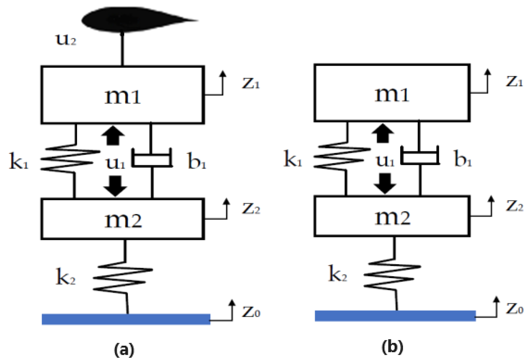
2. Modeling of the Quarter-Car

A two-degrees-of-freedom (DOF) quarter-car model was considered to study the dynamic behavior of the active suspension system in the presence of an active airfoil. As shown in Figure 1a,b, only a quarter of the vehicle is considered. The differential equation governing the dynamic behavior of the car model against the road disturbance is described in Equations (1) and (2).
m 1 z ¨ 1 + k 1 ( z 1 z 2 ) + b 1 ( z 1 ˙ z 2 ˙ ) u 1 u 2 = 0
m 2 z ¨ 2 + k 1 ( z 2 z 1 ) + b 1 ( z 2 ˙ z 1 ˙ ) + k 2 ( z 2 z o ) + u 1 = 0
The model in Figure 1b is extensively used in the literature for studying the performance indices of a quarter-car model. The tire damping coefficient has been neglected, as it is very small [17,18]. The sprung mass displacement, unsprung mass displacement, and road disturbance are represented by z 1 , z 2 and z 0 in the vertical direction from the static equilibrium point. Table 1 depicts the quarter-car model parameters and their corresponding values [8]. These are the normalized values for a typical passenger car and are converted to the actual values when considered for the actual vehicle model.
The dynamics of a quarter-car can be described by the state space model in Equation (3) with zero initial condition:
x ˙ ( t ) = Ax ( t ) + Bu ( t ) + D w ( t ) x ( t 0 ) = x 0
The state vector describing the state variables of the quarter-car model is represented in Equation (4):
x = [ z 1 z 2 , z ˙ 1 , z 2 z 0 , z ˙ 2 ] T , w = [ z ˙ 0 ]
where ( z 1 z 2 ) represents the suspension deflection, z ˙ 1 represents the absolute value of the sprung mass velocity, ( z 2 z 0 ) represents the tire deflection and z ˙ 2 represents the absolute value of the unsprung mass velocity from the static equilibrium point in the vertical direction. ISO 2631-1 [19] guides the evaluation of the effects of mechanical vibration on the comfort of passengers and crew in fixed guide-way systems, defined as the overall comfort and well-being of the vehicle’s occupants during a travel. In the simulation, ( x 2 = z ˙ 1 ) is a state variable and represents the absolute velocity of the car body (chassis), while its time derivative ( z ¨ 1 ) is the acceleration. To assess vehicle ride comfort, especially in the context of a quarter-car active suspension system, the mean squared values of the acceleration of the vehicle body is determined as a measure of ride comfort. The subsequent constant matrices describing the model dynamics of the quarter-car active suspension system with an active aerodynamic surface are shown as follows:
A = 0 1 0 1 k 1 m 1 b 1 m 1 0 b 1 m 1 0 0 0 1 k 1 m 2 b 1 m 2 k 2 m 2 b 1 m 2 , B = 0 0 1 m 1 1 m 1 0 0 1 m 2 0 , D = 0 0 1 0
where the system matrix A is asymptotically stable, and all eigenvalues lie in the left half of the complex plane.

2.1. Aerodynamic Force

The existence of a pressure gradient on a vehicle body can result in a net upward or downward force [20]. The direction of the force is determined from the direction of the gradient. A net upward lift force or downward force can be generated by using an airfoil of a suitable design. Computational fluid analysis performed by [21] shows that the presence of AAS as an air brake can produce a very large downward force on the rear wheel of the car body. The force generated by the aerodynamic surface is the air drag, airlift force, and pitching moments [22]. The magnitude of the drag force depends upon the fluid, surface properties of the vehicle, speed, and specific design features of the airfoil. The magnitude of the lift force and drag force are described in Equations (6) and (7):
F l i f t = 1 2 ρ v 2 S C l i f t ( α )
F d r a g = 1 2 ρ v 2 S C d r a g ( α )
where, v is the speed of the air, ρ is the air density constant, S is the surface area of the airfoil, and α is the angle of attack. At the same time, C l i f t and C d r a g are the lift and drag coefficients, respectively, which depend on the angle of attack, the roughness of the surface, and shape of the airfoil.

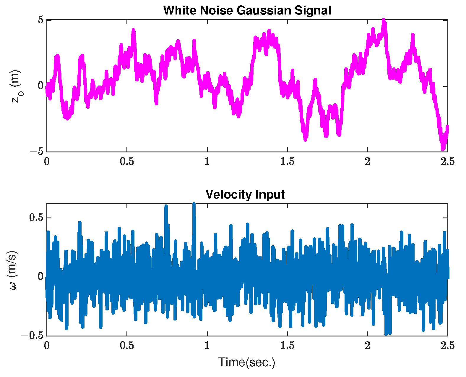
2.2. Road Excitation Model

The ISO 8608 [23] standard is used to approximate different road profiles regarding power spectral density (PSD). There are two methods for describing the road roughness PSD; one is the vertical displacement PSD, while the second is the acceleration PSD. The road surface roughness profile is provided by the relation in Equations (8) and (9):
G d ( n ) = G d ( n 0 ) n n 0 2
G d ( Ω ) = G d ( Ω 0 ) Ω Ω 0 2
where G d ( n 0 ) and G d ( Ω 0 ) are from different road classes. However, the white noise process is characterized by infinite variances and is not realistic [24,25]. A more realistic model for vehicle excitation is stationary Gaussian-colored noise. Thus, the road roughness PSD equation in ISO 8608 has been modified to derive the relationship in Equation (10) [26,27]:
G d ( ω ) = 2 α v σ 2 π 1 w 2 + ( α v ) 2 o r G d ( Ω ) = 2 α σ 2 π 1 ( α ) 2 + ( Ω ) 2
where ω = Ω v , σ 2 is the road surface variance, v is the vehicle speed, ω is the angular velocity, and Ω is the angular spatial frequency. A white noise signal can be transformed to the road profile by either the spatial or time domain through a first-order shaping filter. When the vehicle runs at a constant speed, the PSD defined in Equation (10) can be obtained from the output of the differential equation problem in the time domain, as illustrated by Equation (11):
d d t Z R ( t ) = α v Z R ( t ) + δ ( t )
where δ ( t ) is Gaussian white noise with zero mean, and the PSD is given as 2 α v σ 2 [24,26]. For a detailed investigation of the performance analysis of the quarter-car model with an active aerodynamic surface, the car is subjected to a Gaussian white noise excitation signal, and to a bump input, as shown in Equation (12), which demonstrates extreme event performance properties associated with passenger dissatisfaction. The height of the road bump is 0.1 m which is reported in the literature for the investigation of the minimization of disturbance effects on ride comfort and road-holding. In our earlier work, we considered a road bump with an amplitude of 0.1 m with a vehicle traveling at 20 m/s (72 km/h) [15]. For most vehicles, the rigid body vibrations lie between 0.5 Hz to 15 Hz, which corresponds to a speed limit between 2 m/s to 60 m/s [8,25].
z 0 ( t ) = c 1 cos 20 π ( t 0.3 ) for t 0.3 , 0.4 0 otherwise
The corresponding ground velocity inputs can be represented as follows:
w ( t ) = 20 c π sin 20 π ( t 0.3 ) for t 0.3 , 0.4 0 otherwise
where c = 0.05 m. The covariance of w ( t ) is used to construct the road input for consideration of the proposed simulations, as provided by [8].
E [ w 1 ( t 1 ) w 1 ( t 2 ) ] = 2 π a v 0 δ ( t 1 t 2 )

3. Problem Formulation

The control design strategy involves the full state feedback controller as part of the classic linear quadratic regulator (LQR) model for tracking the input road disturbances and output state regulation stated by [28]. The schematic block diagram shown in Figure 2 describes the approach for rejection of the random disturbances by applying the active aerodynamic force in tandem with actuator control force where all states are available to be detected and fed back [29].
The main objective of the state space model is to design an optimal controller that will minimize the performance indices of the active suspension system using an active aerodynamic surface. By properly selecting the weighting factors, the optimal controller will improve the ride comfort without compromising the road-holding ability. The following assumptions are made regarding the simulation of the quarter-car model:
  • The tire damping coefficient, representing the energy loss due to tire deformation, is considered too small to significantly affect the vehicle dynamics. Thus, it is excluded from the model to simplify the analysis.
  • The model assumes that all state variables, such as the vehicle’s absolute velocity, suspension deflection, and dynamic tire load deflection, can be directly measured or detected from the controller output. This eliminates the need for complex estimations or additional sensor data.
  • In the simulation, only the vertical lift force produced by the airfoil is taken into account to affect the vehicle’s vertical dynamics. Being small, the horizontal drag force is neglected.
  • For simplicity, the model assumes that there are no physical limits on the actuator force and the lift force generated by the active aerodynamic surface. This allows the simulation to focus on and investigate the effects of these forces without considering the complex, constrained dynamics.

4. Optimal Controller Design

This section mainly deals with the design of an optimal feedback controller that will reduce the mean squared values of the passenger compartment acceleration z ¨ 1 , the rattle space ( z 1 z 2 ) , and the dynamic tire load deflection ( z 2 z 0 ) . The controller design is based on an optimal control law that minimizes the quadratic performance index of the active car suspension system [30,31]. The integral cost function of the LQR controller with an active airfoil includes performance indices with suitably selected weights for a typical passenger car, keeping in view the ride quality preferences, and is depicted in Equation (15):
J = lim T 1 2 T 0 T z ¨ 1 2 + ρ 1 ( z 1 z 2 ) 2 + ρ 2 ( z 2 z 0 ) 2 + ρ 3 u 1 2 + ρ 4 u 2 2 d t
where, u 1 is the actuator force and u 2 is the force generated by the active aerodynamic surface. The values of the weighting constants ρ 1 , ρ 2 , ρ 3 , and ρ 4 are selected by the control system designer based on the specific requirements of the suspension system. In this research work, weights ρ 1 and ρ 2 are carefully selected to meet the trade-off between ride comfort and road-holding, ensuring optimal performance under various road excitations. The synthesized performance index can be written in standard linear quadratic regulator form as illustrated in Equation (16) by integrating it numerically over the time T.
J = lim T 1 2 T 0 T ( x T Q x + 2 x T N u + u T R u ) d t
As the aerodynamic force can generate a desired vertical force, provided by [12], this additional force with the actuator force will improve the ride comfort, road-holding, and total dynamic performance index of the quarter-car model. The weighting matrices in the suspension design of the quarter-car model with an active aerodynamic surface are illustrated as follows:
Q = ρ 1 + k 1 2 m 1 2 k 1 b 1 m 1 2 0 k 1 b 1 m 1 2 k 1 b 1 m 1 2 b 1 2 m 1 2 0 b 1 2 m 1 2 0 0 ρ 2 0 k 1 b 1 m 1 2 b 1 2 m 1 2 0 b 1 2 m 1 2 , N = k 1 m 1 2 k 1 m 1 2 b 1 m 1 2 b 1 m 1 2 0 0 b 1 2 m 1 2 b 1 2 m 1 2 , R = ρ 3 + 1 m 1 2 1 m 1 2 1 m 1 2 ρ 4 + 1 m 1 2
where Q is the state weighting matrix, N is the cross term matrix, are positive semi-definite symmetric matrices, and R is a positive definite input weighing matrix [32]. Due to its robust performance, the linear quadratic regulator problem described by [33,34] is augmented with cross term matrix. The Hamiltonian function [35] is used to obtain the optimized values of the proposed control scheme using the constraints from Equation (3). The optimal control force, as shown in Equation (18), minimizes the quadratic cost function obtained using the principle of optimality.
u ( t ) = R 1 ( B T P + N T ) x ( t )
The corresponding steady-state algebraic Riccati equation is given by:
PA n + A n T P PBR 1 B T P + Q n = 0 ,
A n = A BR 1 N T , Q n = Q NR 1 N T ,
where Q n is non-negative definite matrix. The equation needs to be solved by backward substitution for the given boundary condition [36]. Similarly, the state equation of the proposed model and the corresponding closed-loop system matrix are provided in Equations (20) and (21), respectively.
x ˙ ( t ) = A c + D w ( t )
A c = A n BR 1 B T P

5. Results and Discussion

Simulations of the quarter-car active suspension system with an active aerodynamic surface were performed in MATLAB® (R2024a). The physical parametric values and set of weighting factors are illustrated in Table A1 and Table A2, respectively. The first set of weighting factors emphasizes ride quality preferences, while the second set emphasizes road-holding preferences. The performance assessment indices include the mean squared values of the suspension acceleration z ¨ 1 , the suspension rattle space ( z 1 z 2 ) , and the tire deflection ( z 2 z 0 ) . All performance indices are compared to the passive and active suspensions. To investigate the effect of the aerodynamic surface on the performance indices, simulations were performed by considering only the aerodynamic force in the first case and then considering the combined effect of the aerodynamic surface on the active suspension system. To evaluate the performance criterion, simulations were performed for both the frequency and time domains.

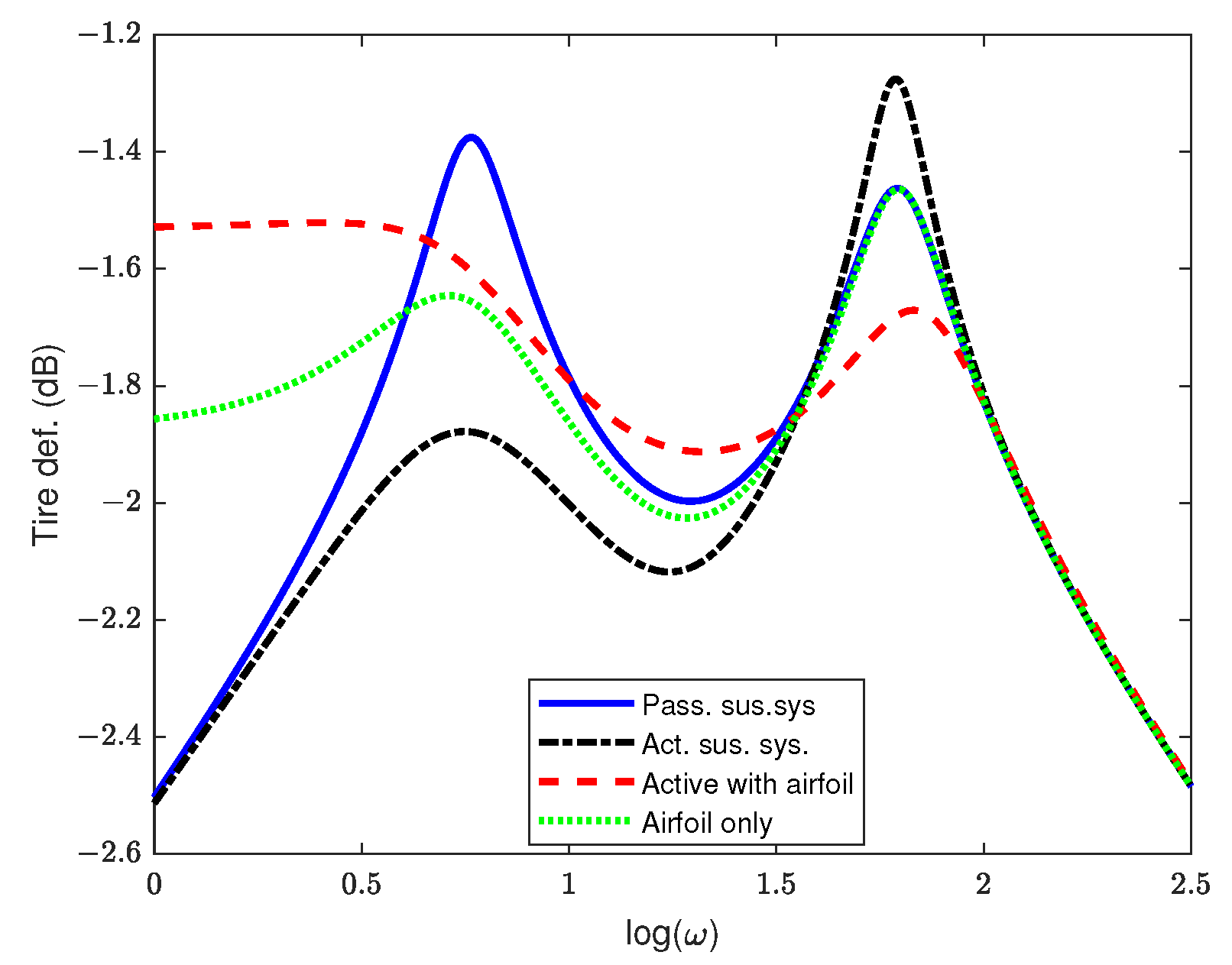
5.1. Frequency Domain Analysis

This section illustrates the simulation results of the 2DOF quarter-car active suspension system with an active aerodynamic surface. The weighting factors emphasize the ride comfort while keeping the tire deformation within nominal values. These values provide lower and upper natural resonant frequencies close to 1 Hz and 10 Hz, respectively. The frequency domain characteristics are determined by taking the Fourier transformation of the closed-loop system matrix, as depicted in Equation (22). Table A1 represents the model parameters selected for the simulation.
| X ( j ω ) / w ( j ω ) | = | ( j ω I A c ) 1 D |
Frequency domain characteristics are evaluated in the presence of a random road velocity excitation signal ω (t) within a specified range of frequency spectrum. Figure 3, Figure 4 and Figure 5 depicts the simulation results for the different performance indices. For each case, the response of the active suspension system with and without the airfoil is computed and analyzed.
Figure 3 illustrates the car body’s dynamic response, highlighting ride comfort by identifying two distinct resonant peaks that remain invariant despite variations in control forces. The low-frequency peak signifies the car body’s hop frequency, which cannot be reduced irrespective of damping efforts. Conversely, the high-frequency peak corresponds to the wheel hop frequency, which maintains an invariant nature under normal conditions. At frequencies other than resonant frequencies, the system damping can be reduced to effectively isolate the car body from external excitations without negatively affecting the tire contact on the road surface. The introduction of an active aerodynamic surface in the study demonstrates significant improvements in both invariant peaks of the car body acceleration, suggesting effective mitigation of vibrations simultaneously across various frequencies. This integrated approach of the aerodynamic surface with actuator force not only lowers the resonant peak frequency but also enhances the overall vehicle dynamics, ensuring improvements in both comfort and handling performance.
To support the vehicle’s dynamic weight, the rattle space requirements are kept within the prescribed level. In the case of the quarter car model, this is quantified by the suspension deflection, as shown in Figure 4. The Figure illustrates that the rattle space requirements are reduced at both resonant frequencies, except the low-frequency range, where the response shows less improvement compared to the passive and active suspension systems. The frequency response, shown in Figure 5, confirms the road-holding capability of the quarter-car model. The tire deflection magnitude is greatly reduced at the tire hope frequency; however, there exists a low-frequency (0–1) Hz range in which the response is worse than that of the active suspension system. However, this is comparable with the passive suspension system, and keeps improving until the second resonant peak is reached. The overall responses in the frequency domain demonstrates that the inclusion of the active aerodynamic surface substantially improves both the ride comfort and road-holding performance of the synthesized model.

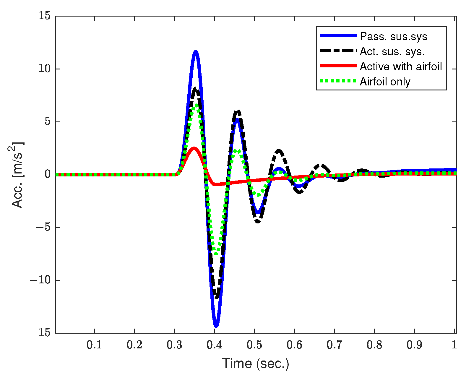
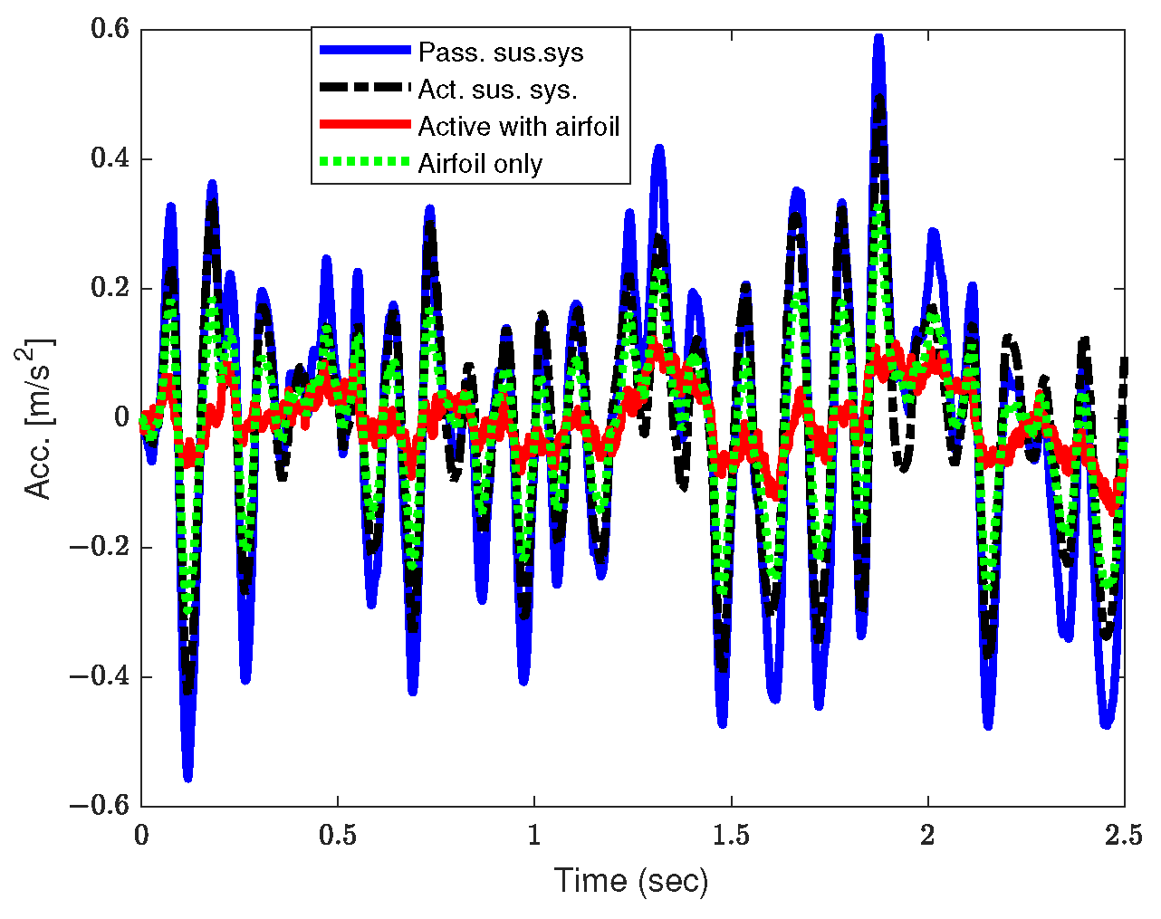
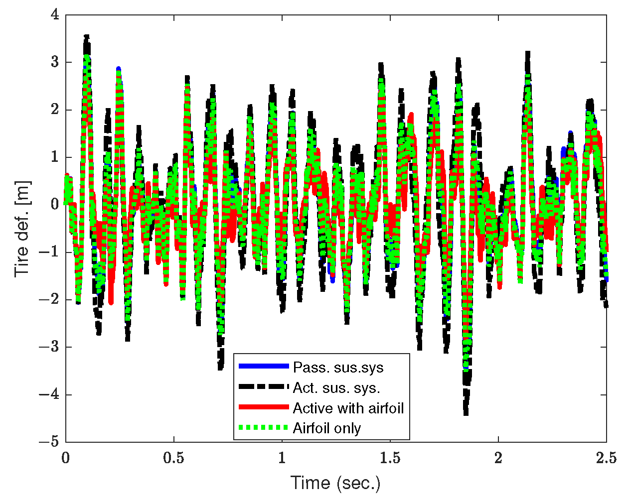
5.2. Time Domain Analysis

This section presents the time domain simulation results of the quarter-car model equipped with an active aerodynamic surface. The numerical simulation results confirm that the proposed system can significantly minimize the variation in the selected performance indices by applying an optimal control force for suppression and disturbance rejection of exogenous noise signals. The performance indices chosen for the time domain simulation were the sprung mass acceleration, suspension deflection, and dynamic tire load. To assess the effectiveness of the suspension system, the car is subjected to two types of random road disturbances. The first type of deterministic disturbance signal is a bump signal with 0.1 m amplitude and the corresponding velocity vector, as shown in Figure 6 while the second type is the asphalt road stationary process Gaussian white noise random signal. Dynamic characteristics of the target performance indices for the first weighting factors are elaborated in Figure 7, Figure 8 and Figure 9. The car body acceleration response of the vehicle to the random bump input in Figure 7 confirms that the active suspension, in combination with the airfoil, produces the best results. Both the car body acceleration and tire deflection are significantly improved.
The mean squared values of the car body acceleration taken over the steady state level are shown in Table 2. The weighting factors of the first set were selected, emphasizing the ride comfort. The results show that car body acceleration is improved by nearly 96%, and the total performance index is improved by 82% compared to active suspension system. At the same time, the dynamic performance of the tire deflection is reduced by about 47% and 68%, respectively, compared to the passive and active suspension systems. These results confirm that the trade-off between car body acceleration and tire deflection is effectively addressed while keeping the suspension deflection within acceptable values.
In the second case, the performance of the suspension system is evaluated by considering ρ 1 = 10 3 and ρ 2 = 10 5 to improve the dynamic model’s traction, braking, and cornering capabilities. In this case, the weighting factors were selected based on road-holding preferences. Table 3 summarizes the results of the second weighting set. The total performance index of the tire deflection is improved by 78% and 74% compared to the passive and active suspension systems, respectively. This enhancement in road-holding capability is achieved while keeping the ride comfort within the same bound. A 38% deterioration in road-holding is observed in the airfoil-only case, while the suspension deflection is exacerbated by 13% compared to the active suspension system. The other performance indices remain within acceptable ranges.
To check the dynamic behavior of the suspension system on asphalt road, a white noise Gaussian signal with zero mean and given standard deviation was applied to the quarter-car model, as shown in Figure 10. The typical values considered for the random road profile are, α = 0.15   m 1 as the constant parameter depending on the type of the road surface, v as the speed of the vehicle moving at 20 m / s , and σ as the standard deviation of the road, having the value σ 2 = 9 × 10 6 m 2 [27].
Figure 11, Figure 12 and Figure 13 show the dynamic responses of the car body acceleration, suspension deflection, and tire deflection. Table 4 refers to the overall improved results when the car is driven on an asphalt road with the first set of weighting factors, while Table 5 shows the results with the second set of weighting factors. The overall trend for the asphalt road shows remarkable improvements, demonstrating that the LQR-based controller with an active aerodynamic surface effectively solves the trade-off between ride comfort and road holding.
In case of asphalt road, the total performance index of the first set of weighting factors is enhanced by 78% and 72% compared to that of the passive suspension and active suspension systems, respectively. When the weighting set is selected to prioritize the tire deflection performance, the total performance index is improved by 61%, while dynamic suspension deflection shows a 1% deterioration compared to the active suspension system and a 31% improvement compared to the passive suspension system. These results are achieved while keeping the ride comfort within the same nominal value. In the airfoil-only case, the tire deflection and suspension deflection show 26% and 11% deterioration, respectively, compared to the active suspension system, while maintaining significant improvement in all performance indices compared to the passive suspension system.

6. Conclusions

In this work, simulation of a quarter-car model equipped with an active suspension system and corroborated by an active aerodynamic surface was modeled and successfully implemented. By designing and suitably tuning the weighting factors based on ride comfort and road holding preferences, the variation in the key performance indices of the quarter car model can be significantly minimized using the optimal controller. Initially, the dynamic response to a periodic sinusoidal signal was examined in the frequency domain, revealing reductions in both the car body hop and wheel hop frequencies. However, low-frequency responses of suspension rattle space and dynamic tire load exhibited poor performance compared to a passive suspension system. Nevertheless, improvements near the car body hop frequency and tire hop frequency were observed in both the suspension deflection and dynamic tire load responses. Subsequently, different performance indices of the suspension system were evaluated in the time domain under extreme event condition such as car bump. Results indicated substantial improvements when weighting factors were selected based on ride comfort and road-holding, showing improvements in ride comfort of 96% and 97% and dynamic tire deflection of 68% and 62%, respectively. Similar trends were observed against the random stationary white Gaussian noise signal when the car was driven on asphalt road. In the airfoil-only case, enhancements in car body acceleration of 55% and 20% were obtained for the first and second sets of weighting factors, respectively. The overall improved results confirm that the proposed system successfully addresses the trade-off between ride comfort and road-holding capabilities, outperforming all other suspension systems in terms of both safety and total performance. The same model can be applied in the future for detailed investigations into the aerodynamic effects on a full-car model while considering variations in the symmetry of the airfoil.

Author Contributions

S.B.A. surveyed the background of this research, presented the problem formulation, and designed the control strategy and MATLAB simulations for the given problem. I.Y. helped in the validation of the research work and reviewing the manuscript, and assisted in the technical writing and MATLAB simulations. I.Y. conceptualized the research idea and supervised the research. All authors have read and agreed to the published version of the manuscript.

Funding

This Research work was supported by the Brain Korea 21 Program for Leading Universities and Students (BK-21 Four Program) funded by the Ministry of Education, Management no. 4120240314862, GNU Graduate Education and Research Program for Mechanical and Aerospace Engineers.

Data Availability Statement

All data are contained within the article.

Conflicts of Interest

The authors declare no conflicts of interest.

Abbreviations

The following abbreviations are used in this manuscript:
LQRLinear Quadratic Regulator
AASActive Aerodynamic Surface
DOFDegrees of Freedom
PSDPower Spectral Density

Appendix A

Table A1. First set of weighting factors used in the performance index.
Suspension SystemWeight ( ρ 1 )Weight ( ρ 2 )Weight ( ρ 3 )Weight ( ρ 4 )
Active Sus. System 10 3 10 4 0.10.001
Active Sus. with Airfoil 10 3 10 4 0.10.001
Airfoil only 10 3 10 4 0.11
Table A2. Second set of weighting factors used in the performance index.
Suspension SystemWeight ( ρ 1 )Weight ( ρ 2 )Weight ( ρ 3 )Weight ( ρ 4 )
Active Sus. System 10 3 10 5 0.10.001
Active Sus. with Airfoil 10 3 10 5 0.10.001
Airfoil only 10 3 10 5 0.11

References

  1. He, D.; He, W.; Song, X. Efficient predictive cruise control of autonomous vehicles with improving ride comfort and safety. Meas. Control 2020, 53, 18–28. [Google Scholar] [CrossRef]
  2. Cvok, I.; Hrgetić, M.; Hoić, M.; Deur, J.; Ivanovic, V. Design of a linear motor-based shaker rig for testing driver’s perceived ride comfort. Mechatronics 2021, 75, 102521. [Google Scholar] [CrossRef]
  3. Mata-Carballeira, Ó.; del Campo, I.; Asua, E. An eco-driving approach for ride comfort improvement. IET Intell. Transp. Syst. 2022, 16, 186–205. [Google Scholar] [CrossRef]
  4. Tang, X.; Duan, Z.; Hu, X.; Pu, H.; Cao, D.; Lin, X. Improving Ride Comfort and Fuel Economy of Connected Hybrid Electric Vehicles Based on Traffic Signals and Real Road Information. IEEE Trans. Veh. Technol. 2021, 70, 3101–3112. [Google Scholar] [CrossRef]
  5. Sadeghi, J.; Rabiee, S.; Khajehdezfuly, A. Effect of Rail Irregularities on Ride Comfort of Train Moving Over Ballast-Less Tracks. Int. J. Struct. Stab. Dyn. 2019, 19, 1950060. [Google Scholar] [CrossRef]
  6. Liu, C.; Chen, L.; Yang, X.; Zhang, X.; Yang, Y. General theory of skyhook control and its application to semi-active suspension control strategy design. IEEE Access 2019, 7, 101552–101560. [Google Scholar] [CrossRef]
  7. Desai, R.M.; Jamadar, M.E.H.; Kumar, H.; Joladarashi, S.; Rajasekaran, S.; Amarnath, G. Evaluation of a commercial MR damper for application in semi-active suspension. SN Appl. Sci. 2019, 1, 1–10. [Google Scholar] [CrossRef]
  8. Youn, I.; Ahmad, E. Anti-jerk optimal preview control strategy to enhance performance of active and semi-active suspension systems. Electronics 2022, 11, 1657. [Google Scholar] [CrossRef]
  9. Hosseinian Ahangarnejad, A.; Melzi, S. Numerical analysis of the influence of an actively controlled spoiler on the handling of a sports car. J. Vib. Control 2018, 24, 5437–5448. [Google Scholar] [CrossRef]
  10. Diba, F.; Barari, A.; Esmailzadeh, E. Handling and safety enhancement of race cars using active aerodynamic systems. Veh. Syst. Dyn. 2014, 52, 1171–1190. [Google Scholar] [CrossRef]
  11. Piechna, J. A Review of Active Aerodynamic Systems for Road Vehicles. Energies 2021, 14, 7887. [Google Scholar] [CrossRef]
  12. Corno, M.; Bottelli, S.; Panzani, G.; Spelta, C.; Tanelli, M.; Savaresi, S.M. Performance Assessment of Active Aerodynamic Surfaces for Comfort and Handling Optimization in Sport Cars. IEEE Trans. Control Syst. Technol. 2015, 24, 189–199. [Google Scholar] [CrossRef]
  13. Wu, Y.; Chen, Z. Improving road holding and ride comfort of vehicle using dual active aerodynamic surfaces. In Proceedings of the 2018 2nd International Conference on Robotics and Automation Sciences (ICRAS), Wuhan, China, 23–25 June 2018; IEEE: New York, NY, USA, 2018; pp. 1–5. [Google Scholar]
  14. Ahmad, E.; Iqbal, J.; Arshad Khan, M.; Liang, W.; Youn, I. Predictive control using active aerodynamic surfaces to improve ride quality of a vehicle. Electronics 2020, 9, 1463. [Google Scholar] [CrossRef]
  15. Ahmad, E.; Youn, I. Performance Improvement of a Vehicle Equipped with Active Aerodynamic Surfaces Using Anti-Jerk Preview Control Strategy. Sensors 2022, 22, 8057. [Google Scholar] [CrossRef] [PubMed]
  16. Gao, W.; Kong, X.; Deng, Z.; Yu, W.; Wu, Y.; Luo, J. Review of state of the art in active aerodynamic control research for vehicles. In Proceedings of the Journal of Physics: Conference Series; IOP Publishing: Bristol, UK, 2021; Volume 1985, p. 012040. [Google Scholar]
  17. Gu, X.; Zhao, B.; Liu, Y. Optimal nonlinear polynomial control of a quarter-vehicle suspension system under harmonic and random road excitations. J. Low Freq. Noise Vib. Act. Control 2023, 14613484231189971. [Google Scholar] [CrossRef]
  18. Kim, Y.-J.; Sohn, Y.; Chang, S.; Choi, S.-B.; Oh, J.-S. Vibration Control of Car Body and Wheel Motions for In-Wheel Motor Vehicles Using Road Type Classification. Actuators 2024, 13, 80. [Google Scholar] [CrossRef]
  19. Karim Afshar, K.; Korzeniowski, R.; Konieczny, J. Evaluation of Ride Performance of Active Inerter-Based Vehicle Suspension System with Parameter Uncertainties and Input Constraint via Robust H Control. Energies 2023, 16, 4099. [Google Scholar] [CrossRef]
  20. Ganesan, S.; Thiyagarajan, R.; Khan, P.A.K.M. Aerodynamic Performance Assessment on Typical SUV Car Model by On-Road Surface Pressure Mapping Method; Technical Report; SAE Technical Paper; SAE International: Warrendale, PA, USA, 2021. [Google Scholar]
  21. Stadler, M.; Nordin, J.; Rama, K.; Sjöstrand, P.; Falkovén, A.; Rask, A. CFD-analysis of the aerodynamic properties of a Mercedes-Benz 300SLR. 2015. [Google Scholar]
  22. Corno, M.; Bottelli, S.; Tanelli, M.; Spelta, C.; Savaresi, S.M. Active control of aerodynamic surfaces for ride control in sport vehicles. IFAC Proc. Vol. 2014, 47, 7553–7558. [Google Scholar] [CrossRef]
  23. Benhiba, A.; Bybi, A.; Alla, R.; Drissi, H.; Nabti, M.; Chater, E.A. Modeling and simulation of vibrational energy harvesting from passive car suspension subjected to random excitations. In Proceedings of the 2022 2nd International Conference on Innovative Research in Applied Science, Engineering and Technology (IRASET), Meknes, Morocco, 3–4 March 2022; IEEE: New York, NY, USA, 2022; pp. 1–9. [Google Scholar]
  24. Lenkutis, T.; Čerškus, A.; Šešok, N.; Dzedzickis, A.; Bučinskas, V. Road surface profile synthesis: Assessment of suitability for simulation. Symmetry 2020, 13, 68. [Google Scholar] [CrossRef]
  25. Tyan, F.; Hong, Y.-F.; Tu, S.-H.; Jeng, W.S. Generation of random road profiles. J. Adv. Eng. 2009, 4, 1373–1378. [Google Scholar]
  26. Mastinu, G.; Plöchl, M. Road and Off-Road Vehicle System Dynamics Handbook; CRC Press: Boca Raton, FL, USA, 2014. [Google Scholar]
  27. Youn, I. Optimal design of discrete time preview controllers for semi-active and active suspension systems. KSME Int. J. 2000, 14, 807–815. [Google Scholar] [CrossRef]
  28. Babawuro, A.; Tahir, N.; Muhammed, M.; Sambo, A. Optimized state feedback control of quarter car active suspension system based on LMI algorithm. In Proceedings of the Journal of Physics: Conference Series; IOP Publishing: Bristol, UK, 2020; Volume 1502, p. 012019. [Google Scholar]
  29. Rodriguez-Guevara, D.; Favela-Contreras, A.; Beltran-Carbajal, F.; Sotelo, C.; Sotelo, D. A Differential Flatness-Based Model Predictive Control Strategy for a Nonlinear Quarter-Car Active Suspension System. Mathematics 2023, 11, 1067. [Google Scholar] [CrossRef]
  30. Cao, Z.; Zhao, W.; Hou, X.; Chen, Z. Multi-objective robust control for vehicle active suspension systems via parameterized controller. IEEE Access 2019, 8, 7455–7465. [Google Scholar] [CrossRef]
  31. Abut, T.; Salkim, E. Control of Quarter-Car Active Suspension System Based on Optimized Fuzzy Linear Quadratic Regulator Control Method. Appl. Sci. 2023, 13, 8802. [Google Scholar] [CrossRef]
  32. Manna, S.; Mani, G.; Ghildiyal, S.; Stonier, A.A.; Peter, G.; Ganji, V.; Murugesan, S. Ant colony optimization tuned closed-loop optimal control intended for vehicle active suspension system. IEEE Access 2022, 10, 53735–53745. [Google Scholar] [CrossRef]
  33. Akgul, T.; Unluturk, A. Comparison of PSO-LQR and PSO-PID Controller Performances on a Real Quarter Vehicle Suspension. In Proceedings of the 2023 Innovations in Intelligent Systems and Applications Conference (ASYU), Sivas, Turkiye, 11–13 October 2023; IEEE: New York, NY, USA, 2023; pp. 1–6. [Google Scholar]
  34. Aljarbouh, A.; Fayaz, M. Hybrid modelling and sliding mode control of semi-active suspension systems for both ride comfort and road-holding. Symmetry 2020, 12, 1286. [Google Scholar] [CrossRef]
  35. Uddin, N.; Manurung, A.; Wijaya, R.N.A. Optimal state feedback control design of half-car active suspension system. IAENG Int. J. Appl. Math. 2021, 51, 1–9. [Google Scholar]
  36. Rami, M.A.; Moore, J.B.; Zhou, X.Y. Indefinite stochastic linear quadratic control and generalized differential Riccati equation. SIAM J. Control Optim. 2002, 40, 1296–1311. [Google Scholar] [CrossRef]
Figure 1. Quarter-car models with ( a ) active suspension system with airfoil and ( b ) active suspension system [17].
Vehicles 06 00060 g001
Figure 2. Schematic diagram of the LQR for the quarter-car model.
Vehicles 06 00060 g002
Figure 3. Frequency response of quarter-car body acceleration.
Vehicles 06 00060 g003
Figure 4. Frequency response of quarter-car suspension deflection.
Vehicles 06 00060 g004
Figure 5. Frequency response of quarter-car tire deflection.
Vehicles 06 00060 g005
Figure 6. Bump position input signal and the correspondingly velocity input signal.
Vehicles 06 00060 g006
Figure 7. Quarter-car body acceleration.
Vehicles 06 00060 g007
Figure 8. Quarter-car suspension deflection.
Vehicles 06 00060 g008
Figure 9. Quarter-car dynamic tire deflection.
Vehicles 06 00060 g009
Figure 10. Random asphalt road disturbance.
Vehicles 06 00060 g010
Figure 11. Car body acceleration against the random signal.
Vehicles 06 00060 g011
Figure 12. Suspension deflection against random signal.
Vehicles 06 00060 g012
Figure 13. Tire dynamics deflection against random signal.
Vehicles 06 00060 g013
Table 1. Model parameters of the quarter-car model.
ParametersDescriptionUnitTypical Values
Sprung mass m 1 kg m 1 = 1
Unsprung mass m 2 kg m 2 = 0.1
Suspension Stiffness k 1 N / m k 1 = 36
Tire stiffness k 2 N / m k 2 = 360
Passive damping coefficient b 1 N . s / m b 1 = 3
Table 2. Mean square values of the parameters for ρ 1 = 10 3 , ρ 2 = 10 4 , ρ 3 = 0.1 , and ρ 4 = 0.001 .
Sus. SystemBody Acc. (%)Tire Def. (%)Sus. Def. (%)Per. Index. (%)
Passive Suspension System100100100100
Active Suspension System 68.6810 169.1334 127.0283 92.2245
Active Sus. With Airfoil 2.7996 53.0826 60.7681 15.9775
Airfoil only 28.9152 97.5948 86.7991 45.8832
Table 3. Mean square values of the parameters for ρ 1 = 10 3 , ρ 2 = 10 5 , ρ 3 = 0.1 , and ρ 4 = 0.001 .
Sus. SystemBody Acc. (%)Tire Def. (%)Sus. Def. (%)Per. Index. (%)
Passive Suspension System100100100100
Active Suspension System 119.2224 70.4292 76.0050 83.2563
Active Sus. With Airfoil 3.2570 26.9738 58.3317 21.3165
Airfoil only 29.2532 97.4537 86.6511 79.4737
Table 4. Mean square values of the parameters for ρ 1 = 10 3 , ρ 2 = 10 4 , ρ 3 = 0.1 , and ρ 4 = 0.001 .
Sus. SystemBody Acc. (%)Tire Def. (%)Sus. Def. (%)Per. Index. (%)
Passive Suspension System100100100100
Active Suspension System 60.1320 148.6625 93.9491 81.1510
Active Sus. With Airfoil 5.6040 64.5897 64.3757 22.8602
Airfoil only 29.9404 96.8577 77.8508 47.8331
Table 5. Mean square values of the parameters for ρ 1 = 10 3 , ρ 2 = 10 5 , ρ 3 = 0.1 , and ρ 4 = 0.001 .
Sus. SystemBody Acc. (%)Tire Def. (%)Sus. Def. (%)Per. Index. (%)
Passive Suspension System100100100100
Active Suspension System 116.6701 76.4822 68.8855 86.2889
Active Sus. With Airfoil 6.4173 41.6701 69.2647 33.7318
Airfoil only 30.8231 96.7001 76.9024 79.6017
Disclaimer/Publisher’s Note: The statements, opinions and data contained in all publications are solely those of the individual author(s) and contributor(s) and not of MDPI and/or the editor(s). MDPI and/or the editor(s) disclaim responsibility for any injury to people or property resulting from any ideas, methods, instructions or products referred to in the content.

