3.1. Results
Following the methodology presented in
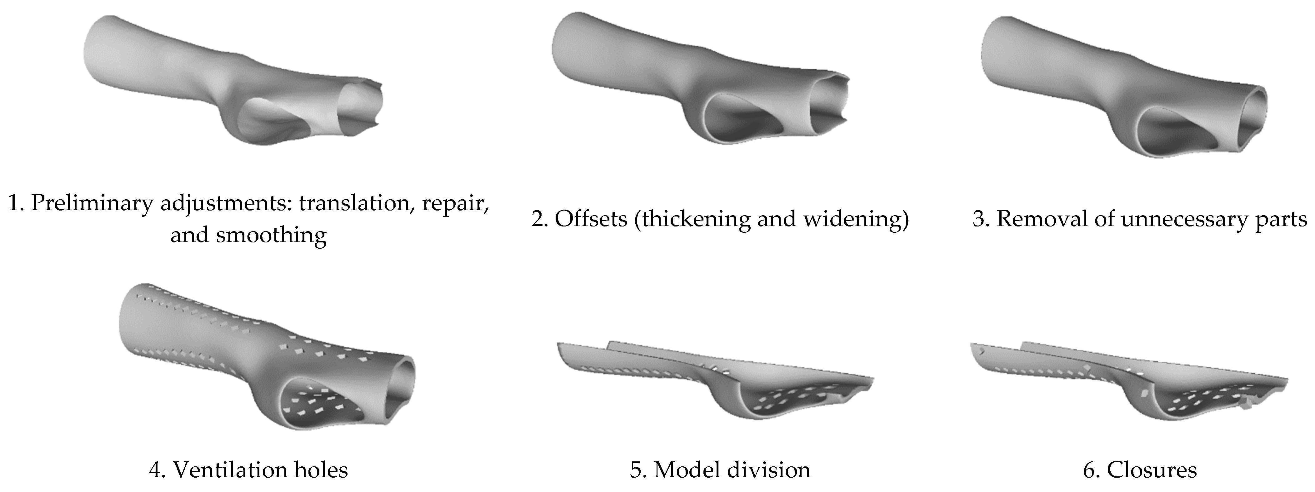
Section 2.2, from a single 3D acquisition, three splint models were designed. All the splint models include a pattern of rhomboidal holes designed to facilitate the ventilation function and lighten the entire structure. The modeling parameters during the CAD stage were kept unchanged except for the offset parameter, which is responsible for creating the solid shape of the scanned surface. Therefore, the three splint models present the same general conformation, while the surface thickness was varied by 2, 3, and 4 mm, respectively. The time, cost, and technical analyses were based on the use of 6 different manufacturing materials, thus, resulting in a total of 18 splint combinations.
As presented in
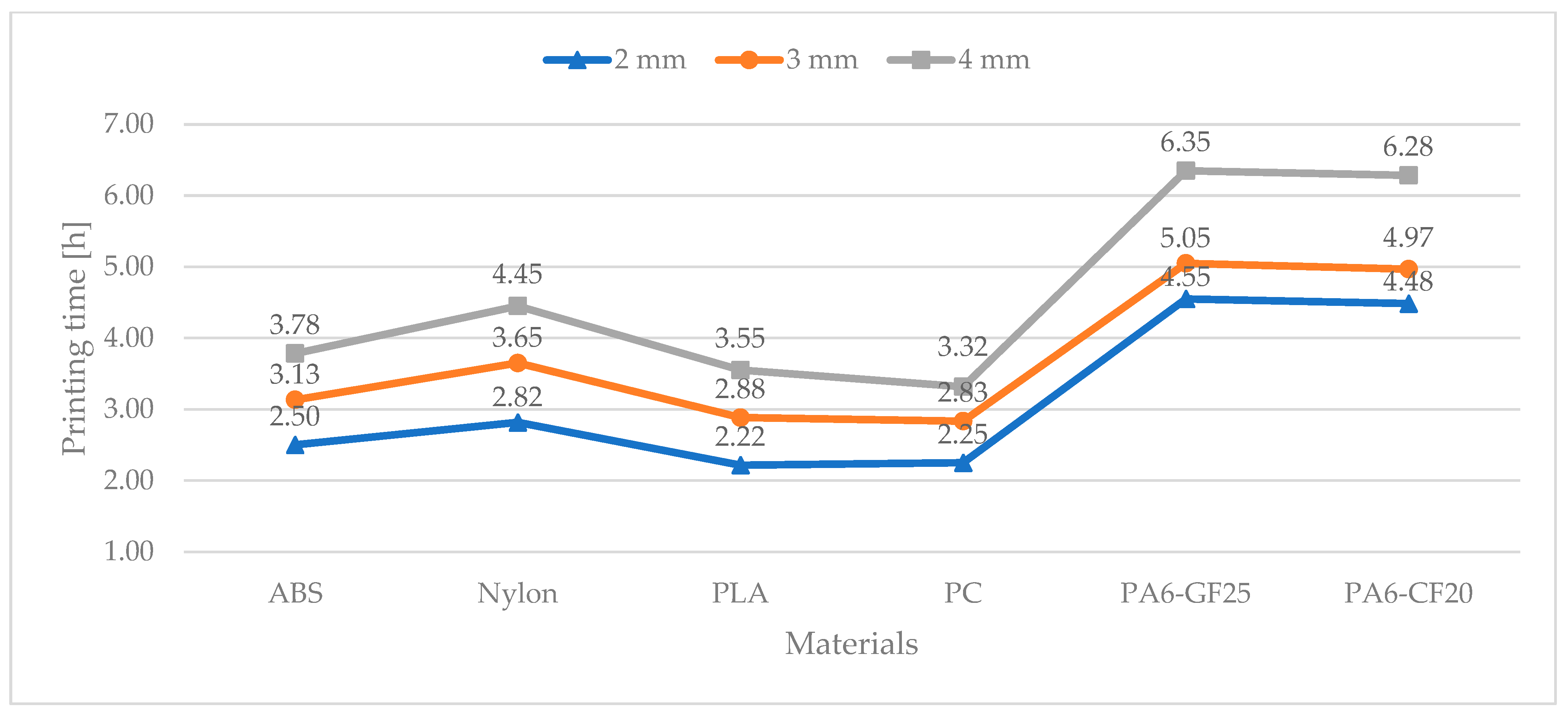
Section 2.4, the splint models were evaluated in terms of time and costs, leveraging the Ultimaker Cura slicing software version 5.3.0. The printing time (
Figure 3) and the amount of extruded material (
Table 4 and
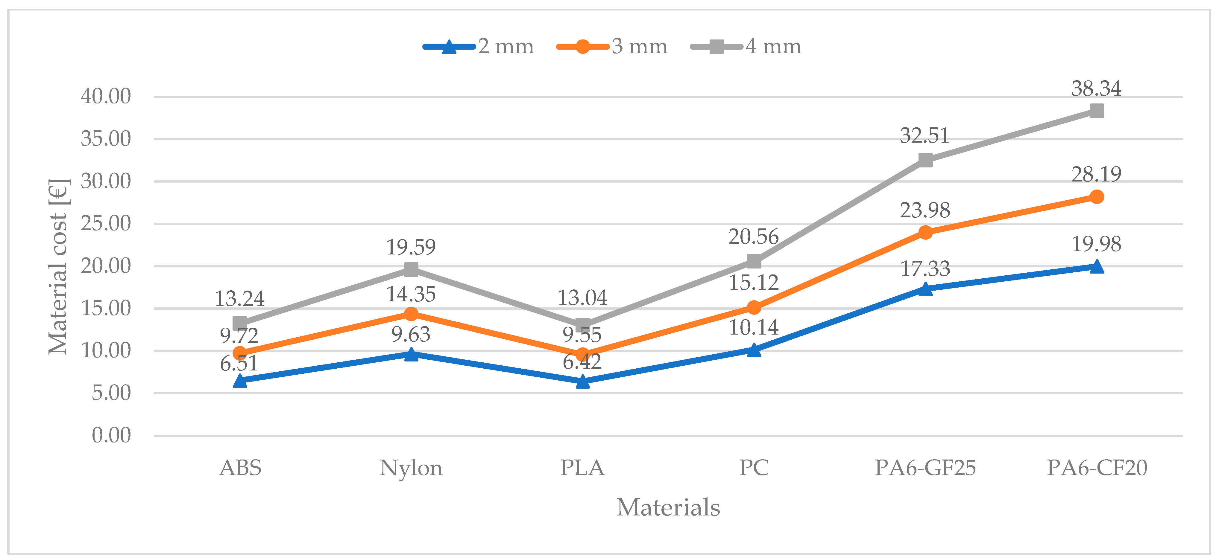
Table 5) of the 18 splint combinations were simulated. From the information on the extruded material, the material weight and material cost (
Figure 4) were derived. The material weight considered only the manufacturing material, whilst the material cost also included the cost component of the support material.
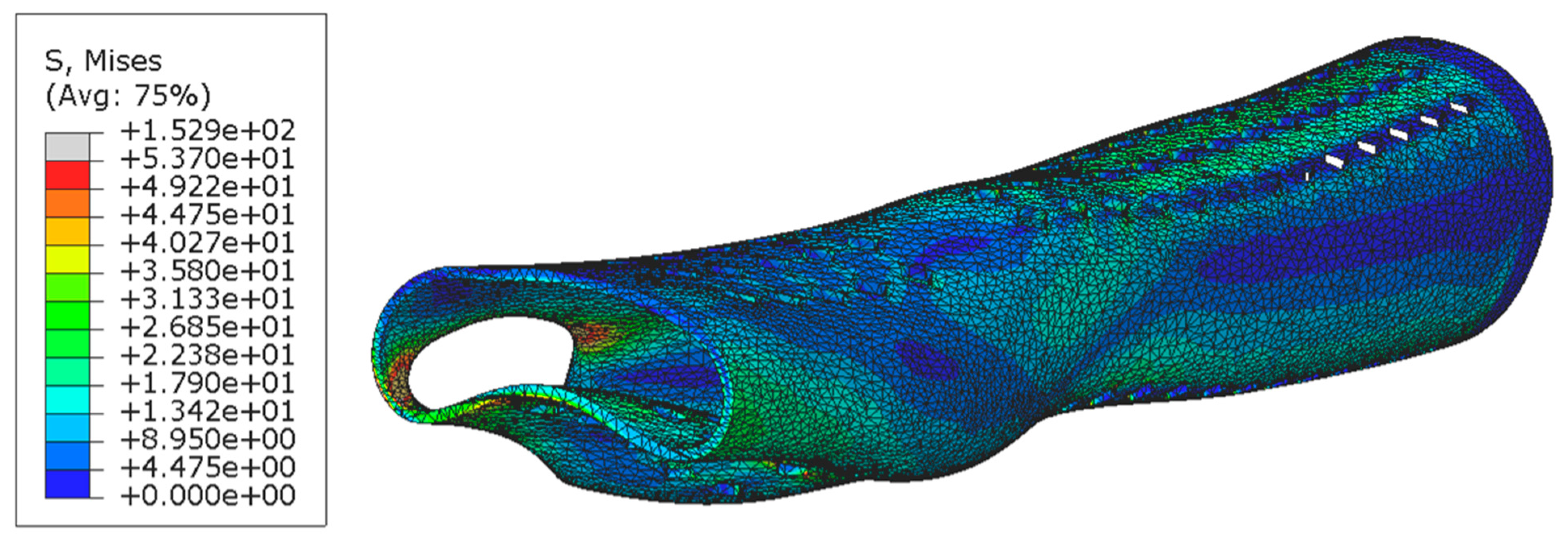
Technical analysis was performed: FEA provided the predicted stresses and displacement distribution maps of the wrist immobilization splint, which were consistent across all scenarios given their sole dependence on geometric factors. For each experiment, the expected maximum stress value was recorded in correspondence of the opening area dedicated to the thumb finger, as shown in
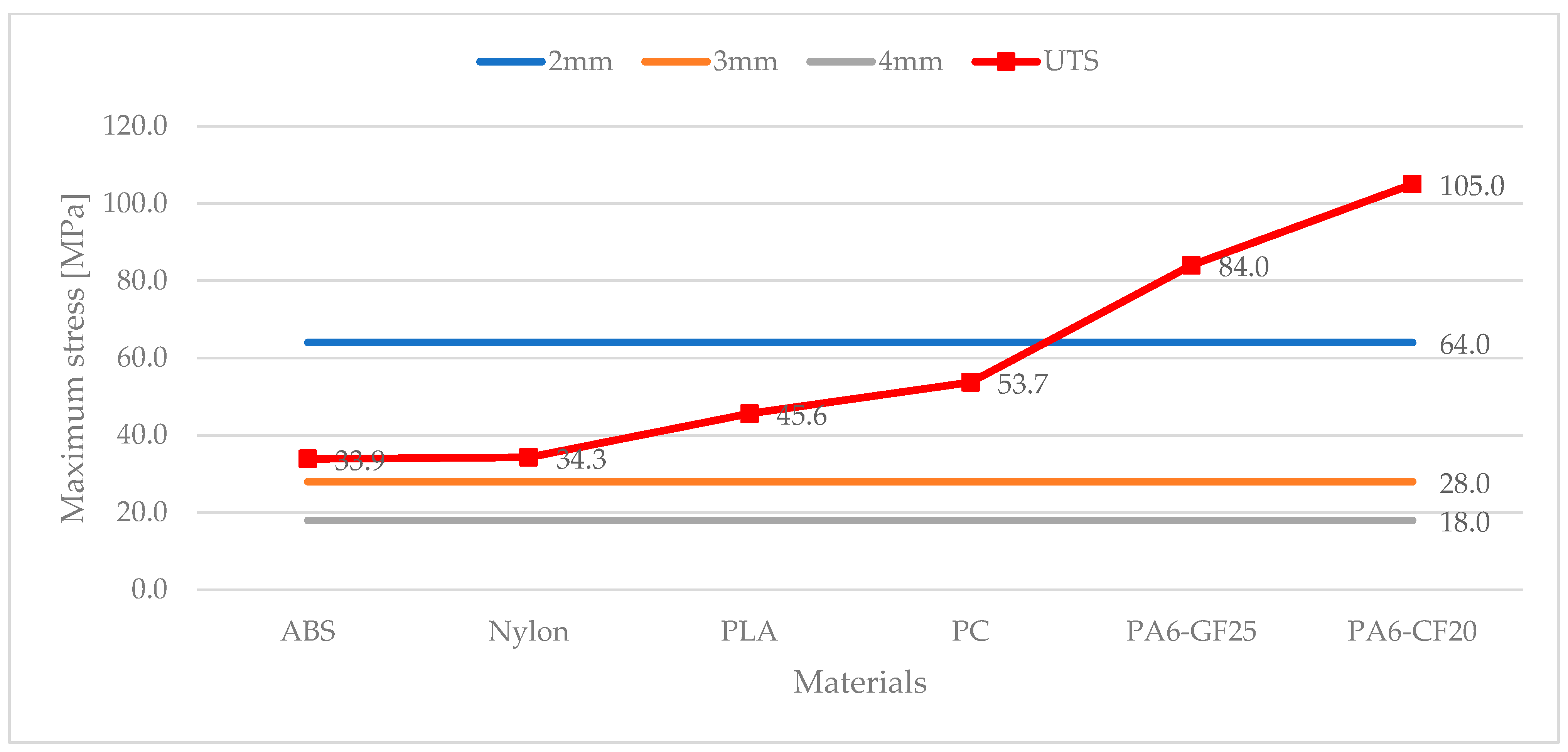
Figure 5. The maximum values of stress were averaged to 64 MPa for a splint configuration of 2 mm, 28 MPa for a splint configuration of 3 mm, and 18 MPa for a splint configuration of 4 mm. The results are presented in
Figure 6 where they are compared to the UTS of each manufacturing material in order to identify the splint combinations capable of withstanding the simulated accidental mechanical impact: the maximum stress values exceeding the material UTS result in splint failure. It is critical to mention that all 18 splint combinations, near the apexes of the ventilation holes, showed a stress intensification effect, which might be limited through the implementation of a fillet radius on every angle of the rhomboidal shape hole.
Concerning displacements, the distribution maps of the 18 splint combinations followed a pattern like the one depicted in
Figure 7.
Table 6 reports the range of the displacement values impacting only the wrist area.
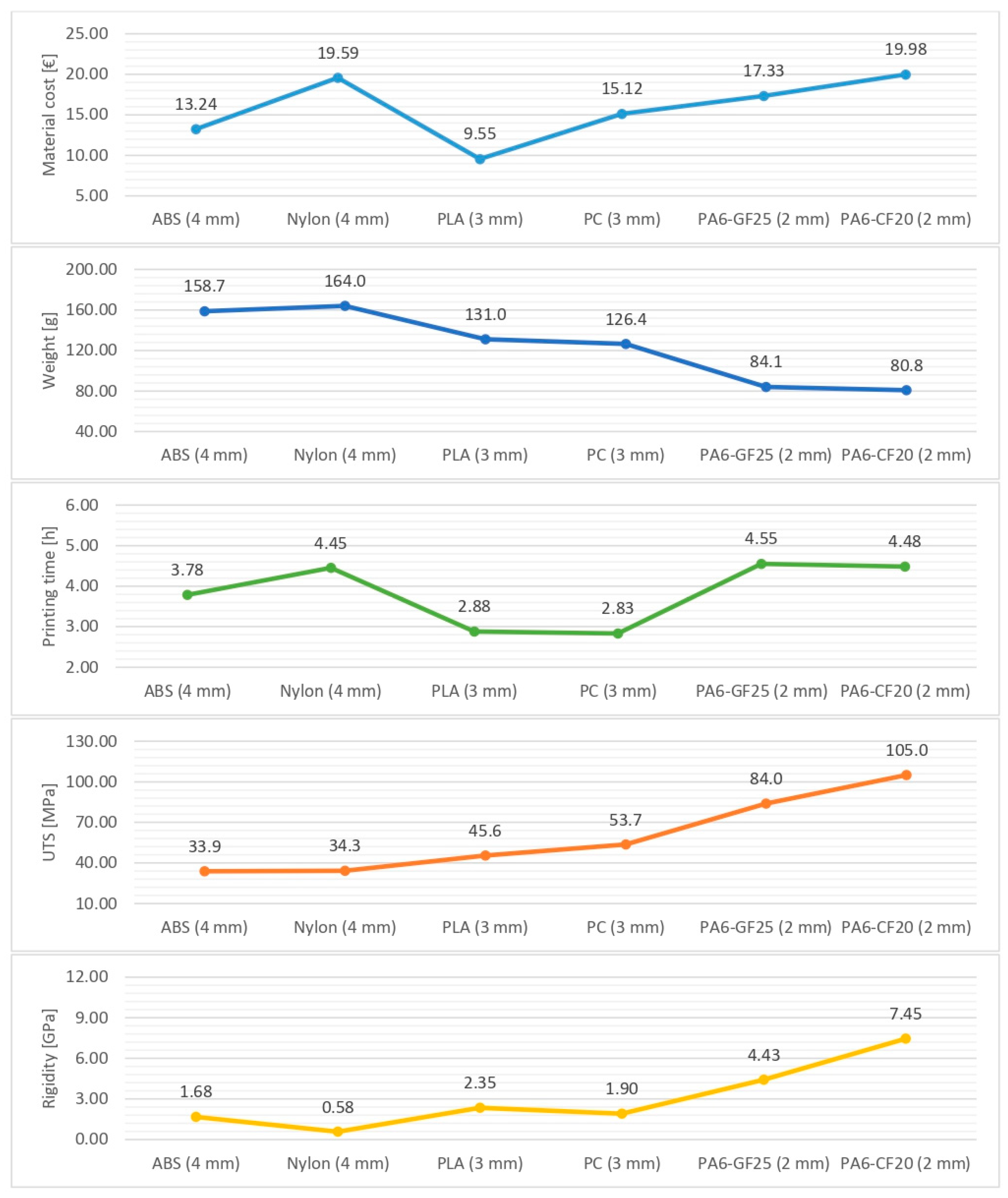
Figure 8 summarizes the key characteristics taken into consideration in the analysis: material cost, weight, printing time, UTS, and rigidity. The figure represents a collection of customized polymer and composite wrist splints in AM characterized by the minimum thickness that allows the part to resist the simulated accidental impact. Precisely, the considered splint configurations were ABS and nylon with a 4 mm surface thickness, PLA and PC with a 3 mm surface thickness, and PA6-GF25 and PA6-CF20 with a 2 mm thickness. The final selection of the six different combinations of materials and thicknesses was based on the safety factor, a numerical value calculated by dividing the UTS of the material by the maximum expected stress experienced by the medical device (respectively to 64 MPa for a splint configuration of 2 mm, 28 MPa for a splint configuration of 3 mm, and 18 MPa for a splint configuration of 4 mm). The considered safety factor was 1.25, and according to some literature studies [
49,
50], it was identified as the appropriate minimum value for rehabilitation devices. Regarding the nylon splint, this arrangement was included for comparative purposes only in light of the inadequate results obtained from the displacement distribution maps.
3.2. Discussion
The analyses conducted on the printing times of the wrist immobilization splints showed that with the considered 3D printing technology (Ultimaker S5 FDM), the material deposition time varied significantly depending on the selected material type and layer thickness. In particular, the material deposition time ranged from a minimum of 2.2 h and a maximum of 6.4 h.
The analysis conducted with the slicing software demonstrated that the estimated times were the result of the sum of multiple components, and the overall time value was attributable to a few leading time components, such as the outer and inner wall deposition and retractions (movement of the head nozzle with the function of avoiding the stringing effect). The time component related to the deposition of the support material did not fit into the aforementioned leading time components since its value was modest as a result of the optimized printing parameters (support overhang angle = 80°) and optimized printing orientation (vertical orientation in the top right quadrant of the printing plane). In fact, for each splint configuration, the recorded support value was always below 8% of the whole printing time.
The composite materials, PA6-GF25 and PA6-CF20, presented by far the highest printing values due to a technical constraint: a narrower FDM nozzle diameter resulted in a reduction in the deposited layer height from 0.6 mm to 0.45 mm. Thus, composite materials demanded a printing time of at least 4.5 h just to realize the thinnest thickness (2 mm). In contrast, for the same level of thickness, the polymeric materials required a shorter printing time, ranging from 2.2 h to 2.8 h. Additionally, the composite printing time was lengthened by the post-printing annealing: it is recommended to anneal (oven at 90 °C for 2 h) the composite prototypes to improve their mechanical and thermal properties. Polymeric prototypes do not require any annealing processes.
With respect to the cost analysis, the value of the total material cost was given by the sum of the manufacturing material and support material cost components. The aggregate material cost ranged from 6 EUR for 2 mm thickness wrist splints manufactured with ABS or PLA to over 30 EUR for 4 mm thickness wrist splints made of composite material.
Comparably to the above-mentioned discussion on the deposition time of the support material, the contribution of the support material component to the total material cost was almost negligible as the amount of support material extruded was minimized. The amount of deposited support material might be subjected to variations due to its close dependence on the model geometry resulting from the scanning and modeling activities. In the present instance, deposition of the support material occurred only at the closures and the opening area dedicated to the thumb finger. The following designs of fastening systems should focus on the realization of systems involving elements that do not protrude from the primary splint structure (e.g., an interlocking closure on the interaction surfaces of the two splint shells). Further adjustments to the opening dedicated to the thumb finger are desirable: the shape of the thumb opening must limit the creation of downward-facing surfaces. These improvements would assure the complete removal of the supporting material, thus eliminating all the issues related to the use of the support material, primarily the prolonged printing time and the rougher surface finish of the areas in contact with the support. Although the support material was used, the main structure of the wrist immobilization splint was still able to self-support during the 3D printing activity.
As a result of the cost and time assessments on the innovative methodology, an advantage in terms of material cost was evident compared to traditional splinting, both pre-manufactured splints and tailor-made splints. Concerning production time, the 3D printing times were substantial, thus making the innovative methodology unfavorable compared to conventional solutions at first glance. To some extent, this drawback might be mitigated through the use of more performant AM technologies that are able to reduce material deposition time. Notwithstanding, when comparing the production times of the traditional procedure with the AM methodology, additional remarks that deviate from the mere amount of time should be made. In particular, it should be noted that the medical application under investigation addresses non-emergency clinical conditions (such as carpal tunnel syndrome, tendinitis, and arthritis). Therefore, from a clinical point of view, there are no real drawbacks associated with the prolonged production time. With no time constraint, the medical solution might be delivered to the patient at a later time (e.g., after an election visit or after a surgical operation) following the limb scanning and splint design. In support of this thesis, it must be noted that the physician’s contribution lies in the scanning and modeling activities. In fact, the active presence of the physician during the 3D printing phase is not mandatory (except for the start-up and the shutdown of the AM machine), as the process is fully automated. Along with the discussion of the applicability and sustainability of the AM splinting process within the clinical practice viewed in terms of production time and material costs, technical aspects aimed at defining the feasibility and functionality of the derived medical devices were considered. Simulations determined the opening area dedicated to the thumb finger as the area of potential fracture. Wrist splint configurations unable to withstand accidental mechanical impact (500 N) were excluded as inadequate at providing a sufficient immobilization function of the wrist joint. The prototypes fabricated with composite materials (PA6-GF25 and PA6-CF20) were the only splint configurations able to resist the simulated mechanical impact at every surface thickness. As for prototypes fabricated with polymeric material (ABS, nylon, PLA, PC), the splint configurations with the smallest surface thickness (2 mm) were not achievable because the maximum recorded stress value exceeded the material UTS. By increasing the thickness to 3 mm, all polymeric prototypes were able to withstand the impact. However, it should be noted that in some cases, like the ABS and nylon prototypes, the maximum stress values were not so different from their UTS such that it is preferable to discard these solutions in favor of wrist splint configurations characterized by a greater thickness. From the stress distribution assessment, the selected splint configurations were ABS and nylon with a 4 mm surface thickness, PLA and PC with a 3 mm surface thickness, and PA6-GF25 and PA6-CF20 with a 2 mm surface thickness.
In addition to the simulations that determined whether the wrist immobilization splint undergoes a rupture, considerable importance was paid to the displacement parameter. The ability of the medical device to provide an adequate immobilization function must assume a limited value of element displacements from their initial location during the execution of the accidental mechanical impact. Technical evaluations reported that the greatest displacement was recorded in correspondence to the extremity of the palm with considerably less impact on the wrist area. As expected, a lower surface thickness exhibited greater displacements. Under the same value of surface thickness, materials characterized by greater flexibility exhibited greater displacements. Specifically, excessive displacement values were registered in customized wrist splints made of nylon (including the configuration presenting a surface thickness of 4 mm), thus undermining their effective immobilization functionality.
Along with the stress and displacement distribution maps, other technical aspects (generally sought by the physician during the traditional fabrication of a customized splint) were involved in the discussion. Observations were made on the conformability and design appearance (e.g., ventilation and thickness) aspects.
Conformability, or the ability of the splint to intimately fit the patient’s arm, no longer depends on the choice of LTT material and the physician’s expertise. Conformability is intrinsic to the process as the customized device is nothing more than a replica of the morphology of the patient’s arm.
Another aspect concerned the perforations, which are intended to favor air exchange while simultaneously reducing the weight of the medical device. Although several LTT materials with various perforation patterns are commercially available, the use of these materials requires extra precaution (e.g., LTT stretching should be limited to not distort hole patterns nor impact the forecasted pressure and strength distribution). The implementation of ventilation holes was facilitated and standardized in the design of a customized splint via AM. Recalling the objective of this study and taking into consideration that the stresses to which the splint was subjected were concentrated in a small portion of the hole, the adoptable configuration was the one with rhomboid-shaped ventilation holes. Other geometries of ventilation holes, such as ellipsoidal or rectangular holes with rounded corners, completely reduced the effect of stress concentrations. However, it should be envisaged that these configurations require the use of additional support material near the holes to avoid the collapse of the structure during printing, thus increasing the 3D printing time. The pattern of rhomboid-shaped ventilation holes was distributed over the front and back surface of the wrist immobilization splint away from the joining zone of the two halves. Future research should take into consideration the possibility of optimizing the hole distribution according to topology, meaning that the configuration should maximize lightness as a function of strength.
A last consideration regarded surface thickness: commonly, the thickness of a film of LTT material is about 3 mm even if thicknesses of 2 and 4 mm are available as well. The customized AM wrist splints achieved thicknesses comparable to those realized with LTT materials with the advantage that the choice of thickness depended only on the desired level of strength and not on the expertise of the medical operator. Conversely, regarding customized orthoses with LTT materials, it is recommended that physicians with less experience use greater thicknesses, as these are more easily moldable.
As anticipated in
Section 3.1 (
Figure 8), all the quantitative results derived from the analyses were gathered together in a comprehensive diagram that may assist medical operators in the process of selecting the most appropriate configuration of a wrist splint according to some key characteristics: material cost, weight, printing time, UTS, and rigidity. Although, from the comparative analysis of each variable, wide differences in the splint configuration chosen were visible, in reality, there was no splint configuration that prevailed in absolute terms.
To conclude, the first 3D-printed prototype for wrist splint immobilization is presented in
Figure 9: the shells were not subjected to surface treatments, and the closure system was integrated with elastomer rings.


