Article

Improvement of Stockbridge Damper Design for Cable-Stayed Bridges

Department of Structural Engineering, Budapest University of Technology and Economics, Műegyetem rkp. 3, H-1111 Budapest, Hungary
*
Author to whom correspondence should be addressed.
Appl. Mech. 2024, 5(4), 818-838; https://doi.org/10.3390/applmech5040046
Submission received: 23 August 2024 / Revised: 27 October 2024 / Accepted: 7 November 2024 / Published: 12 November 2024

Abstract

:
Stockbridge dampers are widely used to mitigate the vibrations of cable-stayed bridges and of many other cable-suspended or cable structures exposed to the action of pedestrians, traffic or wind load. Within the current research work, one of the most effective and likely used damper types, the Stockbridge damper, was investigated to support its design and application within the daily engineering praxis. The Stockbridge damper has a relatively simple structural layout, which ensures its modular design allows it to easily adapt the damper to cables having different dynamic properties (eigenfrequencies, mass, etc.). This paper focuses on two main research areas: (i) to understand the static and dynamic behaviour of the damper and the stay cable interaction to investigate the effectiveness of its damping; (ii) to study the sensitivity of the natural frequencies of the damper to the design parameters. The final aim of the research is to develop a simple design method that is easy to apply in engineering practice and allows the efficient adaptation of the Stockbridge damper to different cable-stayed bridges. Key findings include the recommendation to position the damper at approximately 20% of the cable length for optimal attenuation, the importance of detuning to maintain effectiveness under varying cable forces, and the observation that increasing the damper mass improves efficiency, particularly for detuned elements.

1. Introduction

There are several solutions for damping unwanted cable vibrations in engineering practice, as summarised in [1]. A typical application is the installation of TMD-type damping elements, which have a good damping capacity at some well-defined frequencies (depending on the parameters of the elements). In the case of several cable-stayed bridges, cable vibrations are an issue due to pedestrian or wind-induced loading. Dynamic analysis of these cables shows that high amplitude vibrations can occur at the frequency associated with the first vibration waveform (half sine-wave). Based on this, the goal for each critical cable is effective attenuation at a given frequency or, taking into account, possible retuning around a given frequency, for which TMD-type elements are ideally suited. Within this type, the “Stockbridge damper” type is often chosen for cable-stayed bridges, taking into account the specificities of the bridge, as well as other considerations, including ease of design, aesthetic appearance, durability and ease of replacement.
The Stockbridge damper consists of two flexible steel strands (also known as “messenger cable”), which are attached to a counterweight (damper mass) at either end. The damper is connected to the cable by means of a central grip element (Figure 1). Therefore, the grip element vibrates with the stay cable. Since the two counterweights have a large weight, which means a large inertia, and the stiffness of the steel strand is low, the two counterweights cannot vibrate synchronously with the grip element. As a consequence, internal friction between the strands of the steel strand consumes the vibration energy of the stay cable, restraining the vibration.
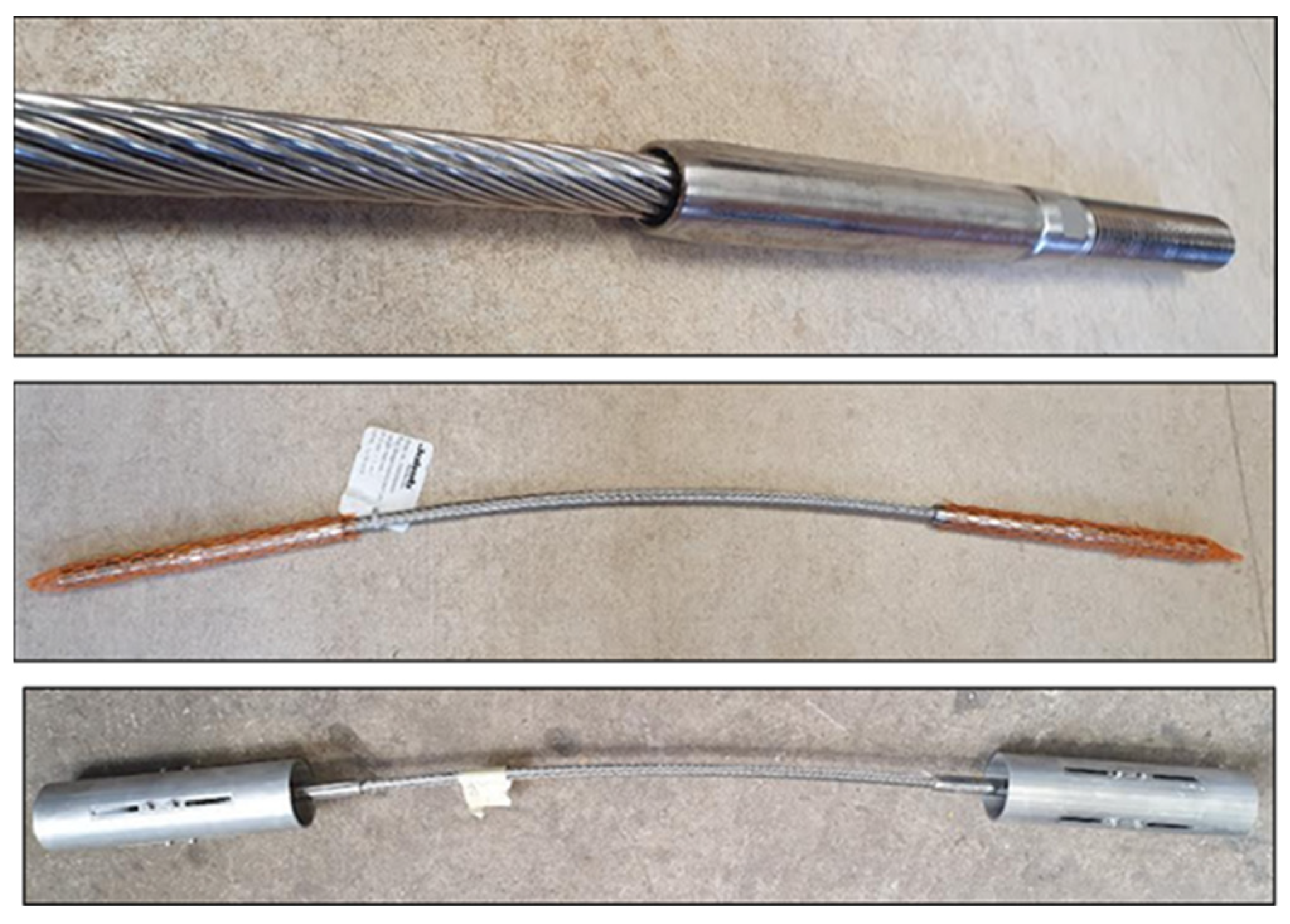
The layout of the damper, as shown in Figure 1, is are the following: a central grip element connects the stay cable and the damper, which can be fixed to the stay cable with metric screws. A messenger cable made of steel strand runs in two directions from the central grip with a special threaded end fixed by pressing. The threaded closing element had been fitted with a cylindrical centrally threaded steel block (adapter element), which is positioned on two sides by locknuts. The cylindrical element cut out of a pipe section can be placed on the steel block through oval holes in the sides to facilitate precise and fine-tuning of the damper and the positioning of the mass adjustment. The cable arrived from the factory with the pressed closing elements as well as the already assembled damper, which are illustrated in Figure 2. This damper has been developed and designed by the Speciálterv Kft. in cooperation with the A-Híd Zrt. and BME Department of Structural Engineering in 2023.
This paper focuses on two main research scopes regarding the design and adjustment of this damper: firstly, to understand the systemic behaviour of the developed Stockbridge damper and the bridge structure, and to study the sensitivity of the natural frequencies of the damper to the design parameters. For the above, two types of numerical models are developed: one is a global model for the system-level study, and the other is an accurate solid element model for the parameter analysis of the natural frequencies. The applied research strategy consisted of the following main steps:
  • Determining the mechanical properties of the messenger cable by laboratory measurements, including the bending stiffness and the logarithmic decrement;
  • Investigating the effectiveness of damping in a global numerical model, taking into account the position of the damper and the relationship between the eigenfrequency of the damper and the stay cable;
  • Investigation of the effect of the design parameters (messenger cable length, counterweight mass, cable diameter) on the natural frequencies of the damper in the local model;
  • Establishing the proposed correlation and checking its reliability.

2. Materials and Methods

2.1. Types of Cable Dampers

As mentioned above, a number of possibilities exist in engineering practice to dampen cable vibrations caused by dynamic effects. One possible approach is an “optimum cable geometry” developed already at the design stage, which, based on preliminary calculations, will not be sensitive to traffic/pedestrian and wind-induced excitations. This may not be possible if other requirements are met, or we may experience adverse vibrations after implementation. This is when the various damping devices are used. In the following, the most commonly used dampers on suspension and cable-stayed bridges will be briefly described with their corresponding simplified mechanical models.
  • Viscous damper: This type of damper is the most commonly used for cable vibration control. The device only allows deformation along the damper axis; therefore, damping can be provided in one direction. In cases where both in-plane and out-of-plane vibration mitigation is required, usually, at least two devices are attached to the same point on the cable. Viscous dampers are frequently modelled as a dashpot with one parameter–viscous coefficient as can be seen in Figure 3a. Experimental results have shown that this coefficient factor is not constant in reality but is frequency-dependent. Various authors conducted research in this field, including experimental and analytical investigations [3,4,5]. Chen et al. [6] found that it generally decreases in value as the vibration frequency increases. In 2015, Sun and Chen [7] showed that frequency dependency may be considered using a fractional viscous model.
  • Viscous shear damper: A viscous shear damper is a viscoelastic damper which can be modelled by the so-called Kelvin model (Figure 3b). Application of this type of damper is common for cable bridges, see [8,9,10,11]. Chen et al. [12] stated that the stiffness and damping coefficients depend on the amplitude and frequency of the dynamic deformation. In the literature, empirical models have been developed to relate the stiffness and damping coefficients to the viscosity of the viscous fluid, the shearing area and the thickness of the shearing layer [13].
  • Friction damper: Friction dampers ideally provide frequency-independent damping. The Coulomb-friction model is widely used to describe the behaviour of the element (Figure 3c). However, time-history responses of a cable-friction damper system, calculated by numerical computation, show larger maximal damping as than in the case of a viscous damper [14]. The explanation might be that this type of element transfers energy to higher vibrational modes, thus dissipating energy more rapidly overall [15,16]. The friction damper is characterised by the stick-slip motion. That means when there is sliding friction between the cable and the damping surface, the vibration of the cable is effectively damped; whereas when the friction surface is stuck, the damping effect is quite small.
  • High damping rubber damper: High damping rubber (HDR) dampers are widely used as internal dampers/deviators for cables [17,18]. This type of damper can be modelled using the linear hysteretic damping model, with a complex stiffness coefficient and a loss factor (Figure 3d). Because of the relatively large intrinsic stiffness effects, which mean a small loss factor, the maximal damping provided by HDR dampers to a cable is relatively small. However, HDR dampers can effectively suppress high-frequency and small-amplitude cable vibrations; this has led to them being widely used.
  • Tuned mass damper: Tuned mass dampers (TMDs) are widely used to dampen vibration in overhead lines and are now also commonly used on stay cables and/or on pedestrian bridges [19,20,21,22]. Its simplified mechanical model is a mass coupled to a viscous damping element and a spring with a given stiffness, as can be seen in Figure 3e. These elements are simple to install and maintain but are limited in their applicability by the fact that, depending on the design, they can only attenuate with high efficiency at some frequencies and less efficiently at other ones [23]. Further valuable research results on this topic can be found in [24,25,26].

2.2. Mechanical Models of Stockbridge Damper

The dynamics of Stockbridge dampers have been examined by numerous authors, firstly for overhead transmission lines [27,28]. Investigations can be divided into two main branches. One is the research on the dynamic characteristics of the Stockbridge damper alone, and the other is the research on the vibration response of the structural system considering the coupling effect of the element to be damped and the Stockbridge damper [29].
One of the most common and simplest models of the Stockbridge damper–cable system is when the conductor is modelled as a beam subjected to an axial load and the Stockbridge damper is reduced to an equivalent discrete mass–spring–mass and viscous damping coefficient [30,31,32], as has been shown before. In 2014, Barry [30] presented a damper-cable model based on a double-beam concept. In this, the main beam with an axial load is a representation of the conductor, and the Stockbridge damper is modelled as an in-span beam with rigid mass at each end.
Another common, also linear, model, which only considers the dynamic behaviour of the damping element, is the 2-degree-of-freedom model presented in [32,33]. In these studies, only the one-side subsystem of the vibration damper was investigated, the counterweight is considered to be a rigid body meaning that, regardless of the elasticity, only the mass and moment of inertia were considered. Since the mass of the messenger cable is far less than that of the damper mass, only the elasticity of the steel strand is considered, ignoring its damping, mass, and moment of inertia. Assuming these simplifications, a system capable of translational and rotational vibrations (Figure 4) was obtained, which is a 2-degree-of-freedom system.
The mechanical models presented above all have in common that they neglect the nonlinear behaviour of the messenger cable. In reality, however, these cables (which are typically made of steel strands) have significant non-viscous damping on bending, which results from the nonlinear nature of the twisting and friction of the elementary fibres [34]. Although this hysteric behaviour has a capital influence in determining the global characteristics of the Stockbridge damper, only a few models can be found in the literature which specifically address the issue of the characterisation of the hysteretic bending behaviour of the messenger cable. Bariberi et al. [34] used a nonlinear cantilever beam with a tip mass as the mathematical model of the damper, which incorporated a nonlinear stiffness matrix of the element due to the nonlinear curvature effect of the beam. Foti and Martinelli [35] developed a model based on a beam-like description of the messenger cable and on a nonlinear formulation of the cross-section’s cyclic bending behaviour. In this, at the cross-sectional level, the mechanical behaviour of the messenger cable is reproduced using the classic Bouc–Wen hysteretic model.
Generally speaking, studies that take into account the nonlinear behaviour of the element use both experimental and/or numerical simulation results. The main objective of this study is to develop a simple empirical relationship that faithfully describes the behaviour of the developed Stockbridge damper, taking into account the nonlinear effect of the inclination of the stay cable. It should be noted, that to establish the researched relationship, laboratory tests and numerical models will be used.

3. Laboratory Measurements of the Mechanical Properties

To investigate the mechanical behaviour of the damping element, it was first necessary to determine the bending stiffness of the messenger cable and the degree of damping, as these became the input data for the numerical models.

3.1. Determination of Cable Stiffness

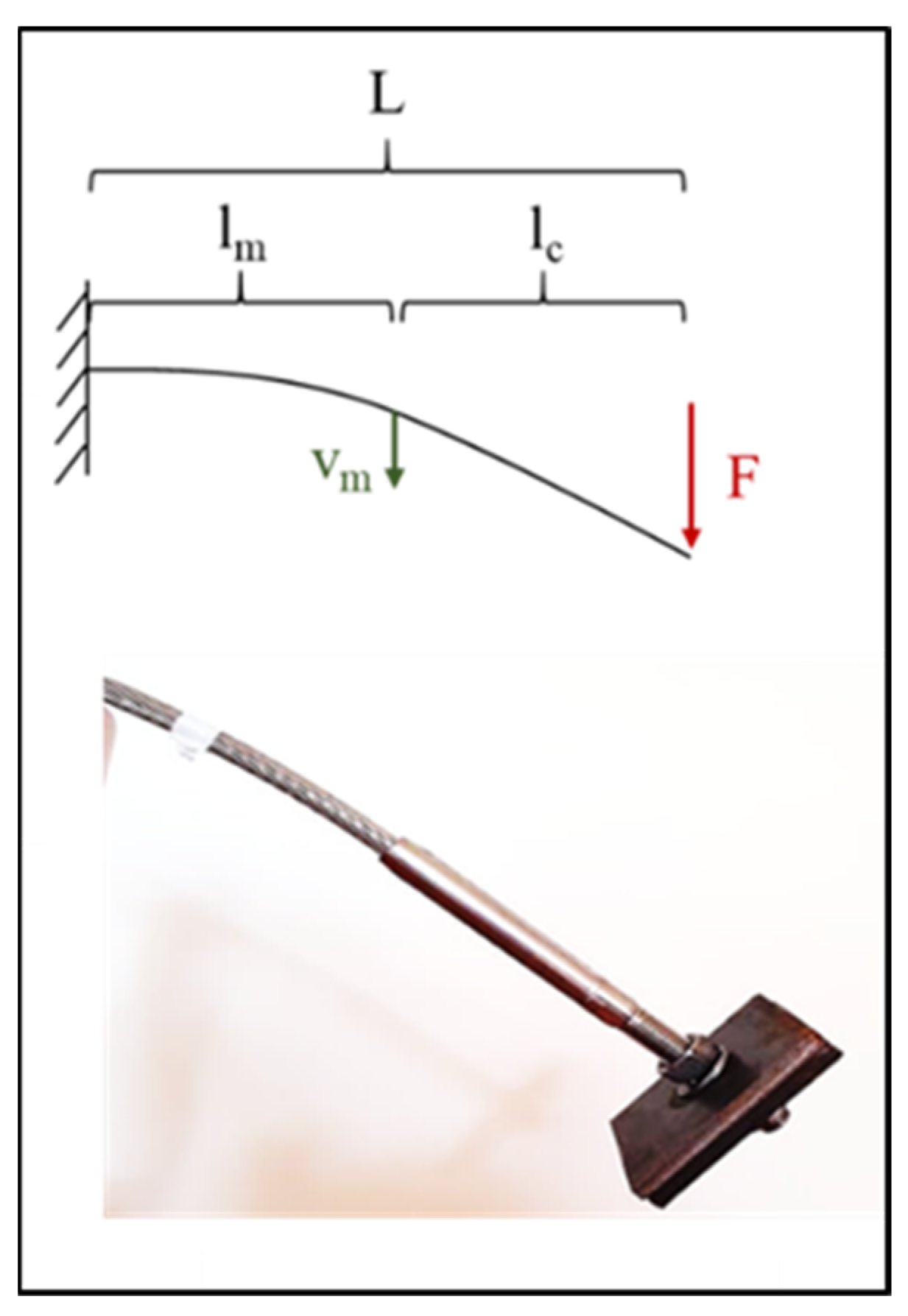
The messenger cable of the manufactured damper is a 12 mm diameter Jakob-made strand, on the end of which a threaded closing element was placed before the experiments started, as its design and the degree of interlocking of the elementary fibres significantly affect the bending stiffness of the strand. During the measurement, the cable was rigidly clamped, and then weights of known magnitude (1/2/3 kg) were placed on the end of the threaded shank, while HBM type WA50 inductive transducers were used to measure the displacement on the boundary between the strand and the closing element. The experimental setup and the measurement principle are shown in Figure 5.
The use of different mass sizes in the measurement was justified by the nonlinear behaviour of the strand. This is explained by the fact that the messenger cable is composed of separate sheaves between which a frictional force occurs. This adhesive friction ensures that the individual strands work together and, when exhausted, the apparent stiffness of the strand decreases. A typical load–deflection diagram is shown in Figure 6.
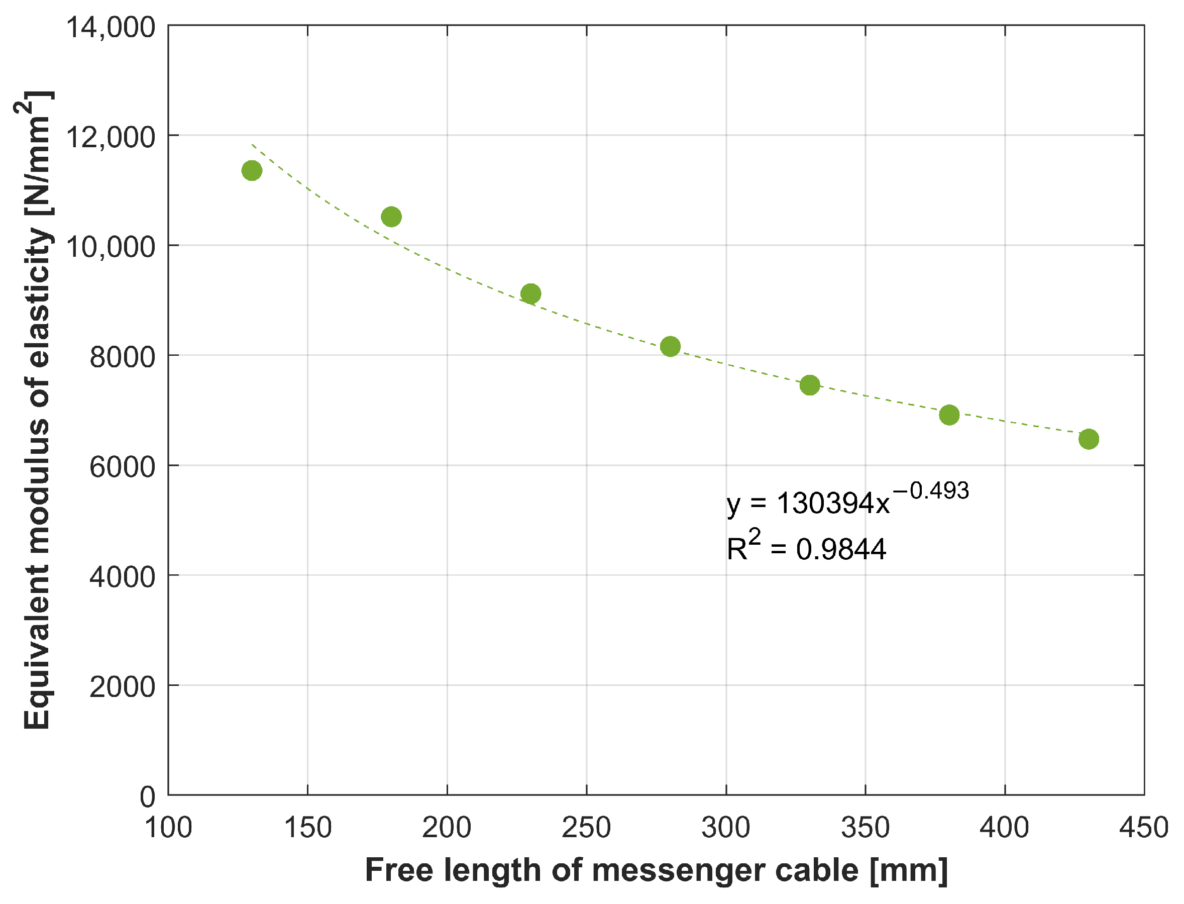
During the measurements, different free messenger cable lengths were examined, since the degree of cooperation of the strands of the wire, thus the equivalent modulus of elasticity, significantly depends on the free length between the clamp and the closing element. Evaluating a total of seven different designs, the resulting equivalent modulus of elasticity is shown in Figure 7 depending on the free length of the messenger cable.

3.2. Determination of the Degree of Damping

The damping test was carried out with a similar experimental setup as the static stiffness test. The difference was that, in this case, the acceleration of the cantilevered strand was measured (perpendicular to the axis) using an HBM type B12 200 accelerometer, and the “load” was an excitation of the pulse type. So, the measurement was performed by testing the damped free vibration of a pulse-like excited cable. An example of the measured acceleration–time function is shown in Figure 8.
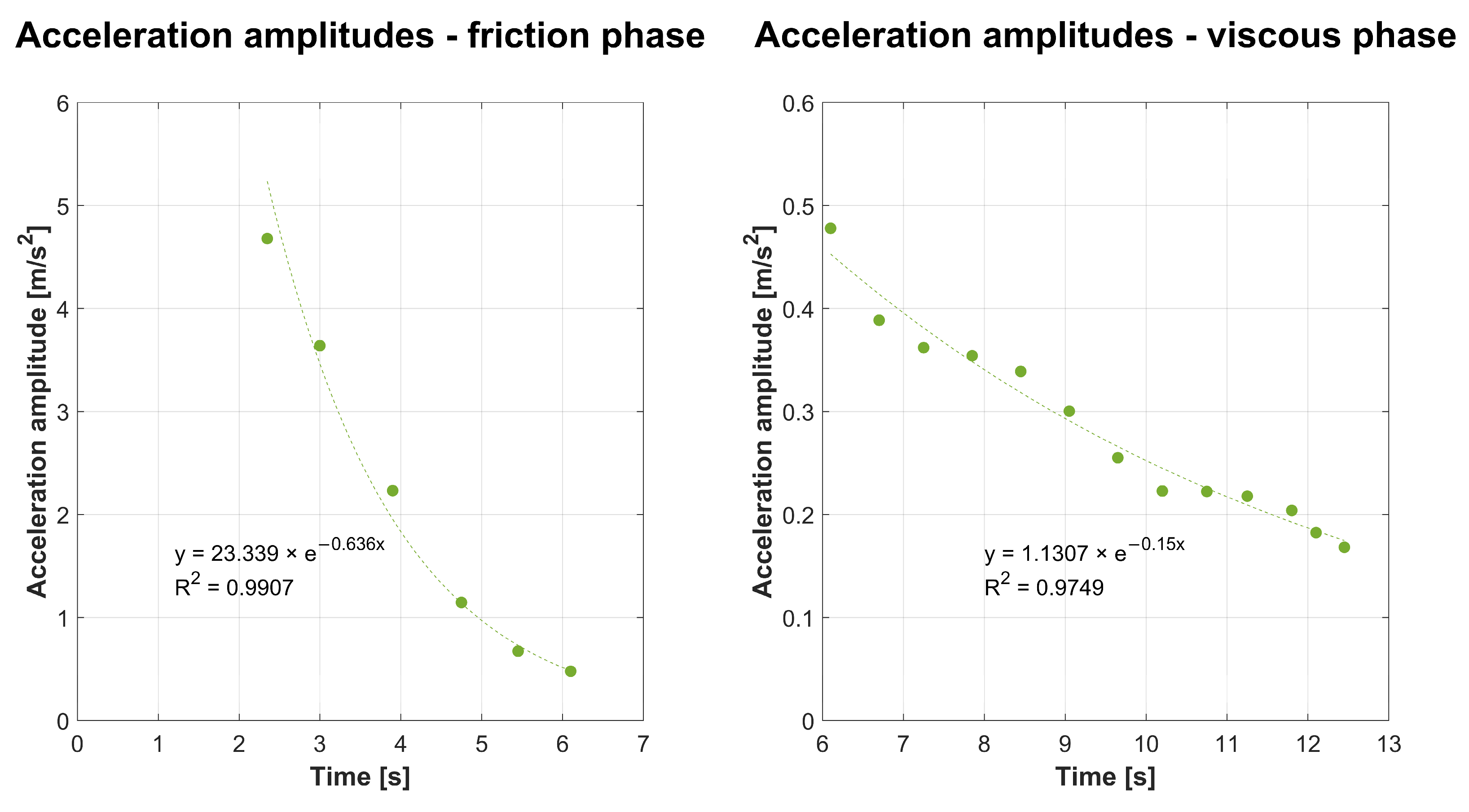
The function obtained clearly shows that the cable attenuation exhibits a dual behaviour. The high-amplitude oscillation that occurs after pulse excitation decays quickly, at this stage, the cable has a high attenuation. However, following this, a smaller amplitude vibration still remains, which damps down more slowly. This behaviour is well explained by the model presented in the stiffness measurement, i.e., the change in friction forces. At high amplitudes, the strands slip on each other, effectively dissipating the energy of the vibration, while at lower amplitudes, the slippage is not, or to a lesser extent, so the energy loss is lower. Thus, the damping phenomenon can be divided into two phases: an initial frictional damping, followed by a viscous damping. An example of the measurement dataset split in this way is shown in Figure 9, with the fitted exponential curves. It can be seen from the exponents of the fitted functions that the two attenuation rates for the two phases are different.
As the natural logarithm of the ratio of successive acceleration amplitudes, the value of the logarithmic decrement (ϑ) for a given phase can be determined from this (assuming low damping), the damping ratio is given by the following formula:
ξ = ϑ 2 π .
As an approximation in favour of safety in the modelling, the logarithmic decrement ϑ = 0.11 was used, which is the minimum value observed in the measurements. The real logarithmic decrement is expected to be larger than this, significantly higher at high vibration amplitudes.

4. Global Numerical Model

To gain a deeper understanding of the behaviour of the Stockbridge damper, the damper system and the stay cable were studied first. To do this, a numerical model was created in ANSYS 19.0 [36] finite element software to answer the following questions: how effective the damper is; where is the recommended position of the damper along the longitudinal axis of the cable to achieve effective damping; and to what natural frequency the two sides of the element need to be tuned in order to ensure effective over the full frequency range of operation.

4.1. Structure of the Global Model

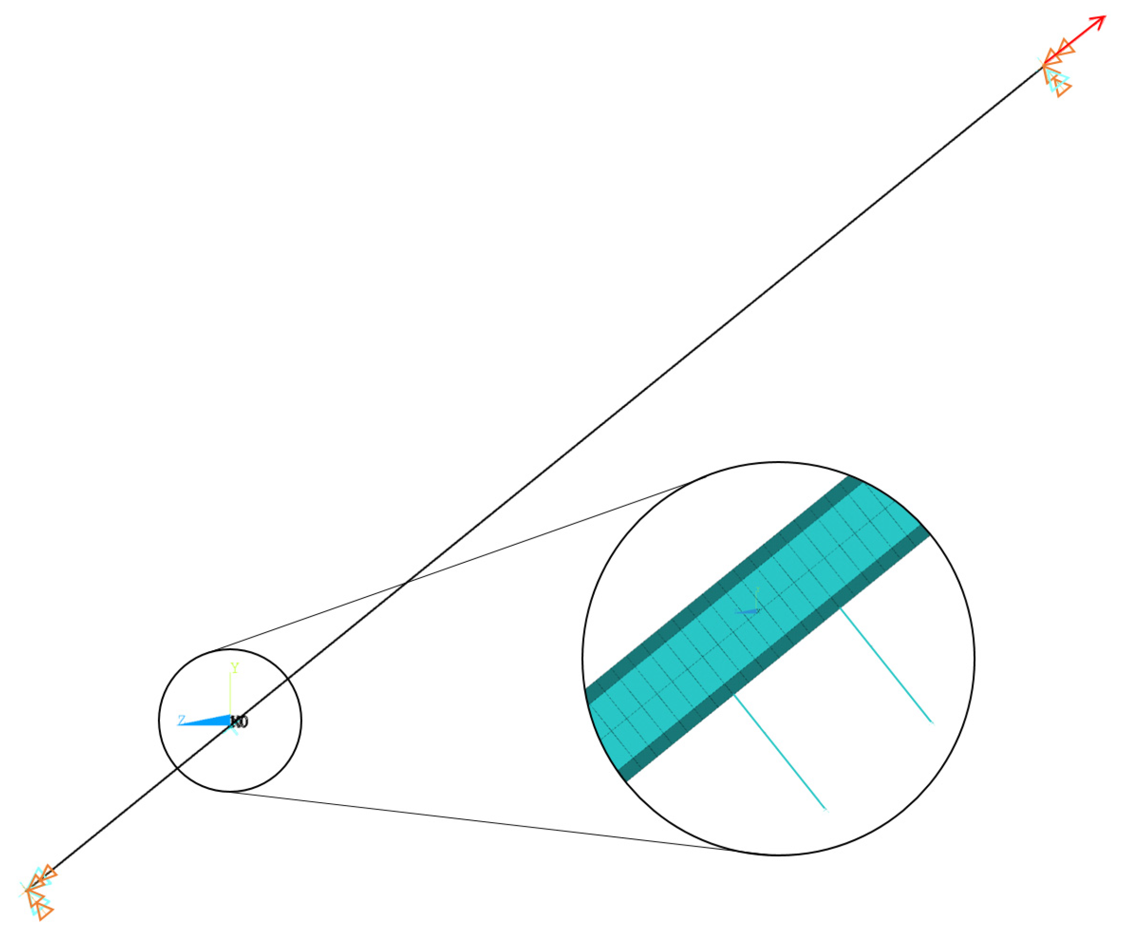
For the investigation of the structural behaviour of the stay cable–damper at the system level, a simpler beam model has been developed. In the numerical model, the stay cable was built up from beam finite elements, the damping element itself was modelled as two mass points and as spring-retarding damping elements connecting them to the corresponding point of the stay cable, for which the characteristic spring constant and damping rate were defined on the basis of laboratory measurements. The mechanical model used thus corresponded to the literature with the modification that, in this model, two mass points were used instead of one (in fact, the developed model is a combination of those presented in [30,33]). This technique allows for a separate treatment of the two branches of the damper in the subsequent local model. The ANSYS model is shown in Figure 10.
To excite the stay cable, a harmonic force was applied with a line of action in the axis of the unloaded cable. This force caused a vibration perpendicular to the axis of the cable because of the sagging effect (this effect was considered by self-weighted cable and geometrically nonlinear analysis), so the line of action of the excitation force does not coincide with the stay cable. The level of excitation was chosen in such a way that, after the initial transient phenomena, the amplitude of the resulting vibration was close to the diameter (~50 mm) of an undamped stay cable vibration, measured at the centre of the cable (middle of the cable along its length).
In the dynamic calculations, harmonic analysis was used on the numerical model to determine the steady-state response of the structure to excitation. This method can be used to determine the response for harmonic excitation of linearly elastic structures with significantly smaller computational effort compared to, for example, a transient analysis. The result is a response spectrum function, which gives the steady-state vibration intensity of the structure at the point of interest under different excitation frequencies. These diagrams clearly show the phenomenon of resonance, that at a given excitation frequency (the natural frequency of the structure), the displacements are significantly larger than at other excitation frequencies.

4.2. Investigating the Effectiveness of Damping

The principle of operation of the Stockbridge damper and based on the laboratory measurements, the higher the amplitude of the vibration the more efficiently the damper works. On this basis, it would seem appropriate to tune the natural frequency of the attenuator to the frequency of the stay cable to be attenuated since this will produce the highest amplitude vibrations in the damper (resonance phenomenon). This can be seen in the graph below, which illustrates the maximum amplitudes calculated from the numerical model as a function of frequency for a damper placed at 10% of the cable length. The curve changes from a single peak to two smaller peaks, indicating that the damper is the most effective at the natural frequency of the cable, as expected.
The first diagram shows that the amplitude of the damper detuned with 20% of the natural frequency of the stay cable is significantly smaller than the amplitude without attenuation (50 mm), so the damper can significantly reduce the cable vibration. The single peak in the detuned case has a larger amplitude than that seen in the tuned case, meaning that the attenuator is not as effective. It should be noted, however, that even in detuned cases the damper was able to reduce the amplitude to the quarter part at 10% position and more than half at 20% position. The difference between the two designs is practically disappearing after 0.1 Hz.
From Figure 11, it can also be seen that the movement of the mass points of the damper is consistent with the cable vibration. In the case of a precisely tuned damper, the centre of gravity has a significant amplitude, the highest at the natural frequency of the cable (this explains its efficiency). Also, in the case of a detuned damper, the mass points of the damper show greater movement at the natural frequency of the cable (this is due to the vibration of the cable), and in addition, there is a peak at the upper and lower damping element’s natural frequency.
On the basis of these phenomena, the use of precisely tuned damping elements still seems reasonable. However, in reality, the static value of the tension force in the stay cables changes due to temperature changes and time-dependent loads. This fluctuation also changes the natural frequency of the cables so that the natural frequency of the damper and the cable over time detune relative to each other, resulting in a change in the attenuation efficiency. This phenomenon was also tested in the numerical model, assuming ± 10 and 20% normal force variation. The results are illustrated in the graphs shown in Figure 12, taking into account the effect of damper and stay cable detuning only, i.e., separating the amplitude variation due to detuning and cable relaxation–tension; eliminating the latter from the model.
From the above diagrams, it can be concluded that the accurately tuned damper efficiency deteriorates with the detuning of the stay cable, while in the detuned case, the efficiency of the damper improves. It follows that detuned dampers are able to work efficiently in a much broader frequency range; this behaviour makes their application logical. Another observation is that when the damper is positioned towards the centre of the cable, the resulting diagrams “slide into each other” in the vertical sense, i.e., even with small changes in cable force, the behaviour of the cable with detuned dampers will be more favourable.

4.3. Investigating the Position of the Damper

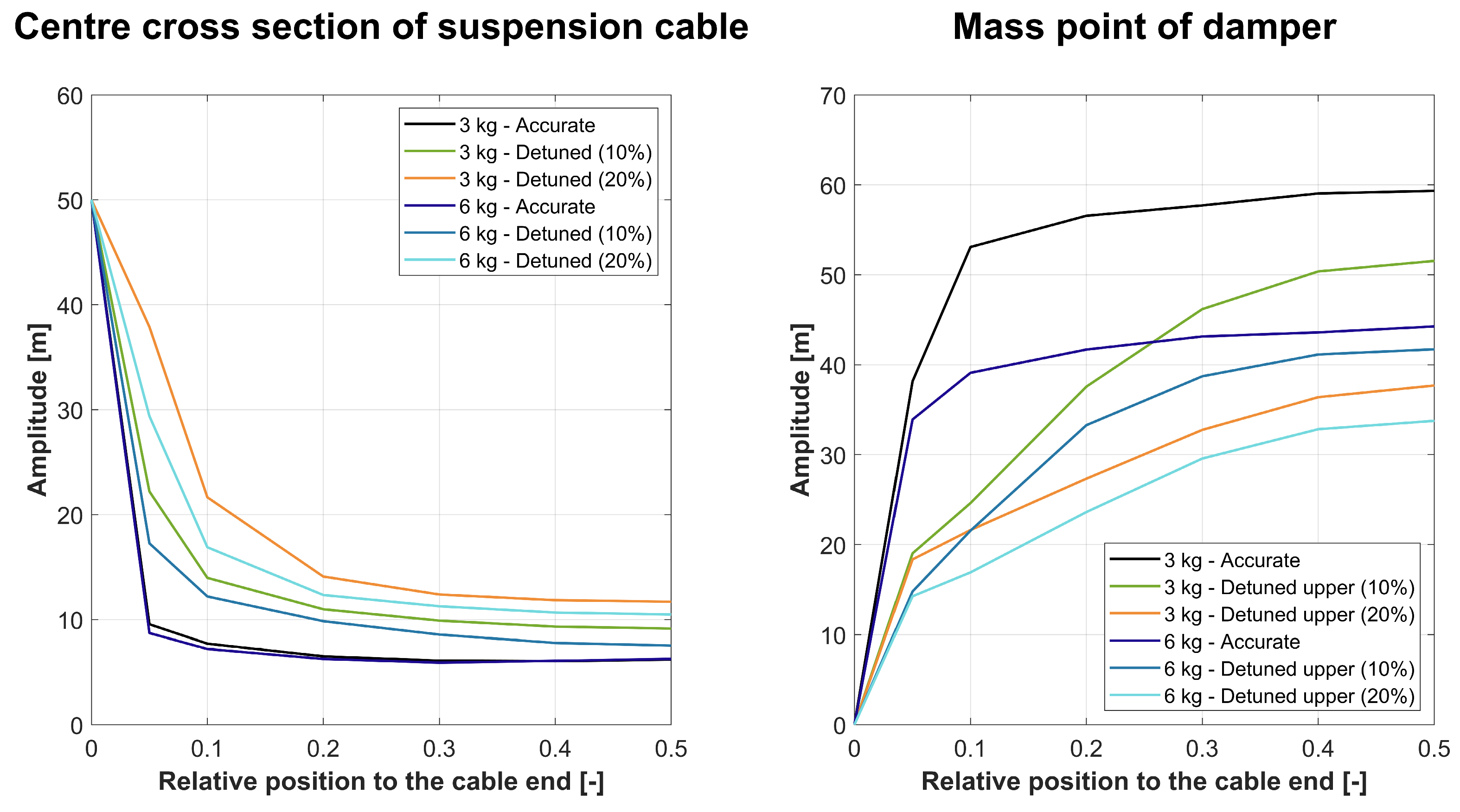
Another important design consideration is where along the longitudinal axis of the cable the damper should be located so that it is sufficiently effective, but at a height where it can be easily mounted but is not accessible to bridge users. The effectiveness of a damper positioned at the end of the cable is negligible, but its installation is simple. In contrast, the most efficient way to operate the damper at the midpoint of the cable since the vibration waveform to be attenuated is a sine half-wave, which has a maximum amplitude in the centre; however, this can be problematic from a mounting point of view. Pursuant to the foregoing, there is an optimal situation where the damping is already sufficiently effective, and the installation is as simple as possible. To investigate this, different runs were run with damping elements placed in different positions along the length of the stay cable in the global model (defined the damper as 0, 5, 10, 20, 30, 40 and 50% of the length), each position in three different configurations (tuned attenuator, 10% detuned and 20% detuned). The results are summarised in Figure 13.
From the first graph, it is clear that the damper is effective, essentially independent of placement, above a certain limit. In the precisely tuned case, the maximum attenuation is already reached at 5% of the cable length, increasing the detuning the limit is pushed slightly higher, but even in the case of the 20% detuned damper, which is not really relevant in practice, the maximum attenuation is already reached at 20% of the cable length.
The nature of the motion of the mass points is illustrated in the second graph. In the precisely tuned case, the distance exceeding 10% of the cable length has essentially no effect on the location of the mass points; the amplitude is significant, close to 60 mm. In the detuned case, the closer the attenuator is to the centre of the cable, the larger the amplitude of the mass points, but the amplitudes are smaller, barely reaching 50 or 40 mm, depending on the degree of detuning.

4.4. Effect of Changing the Vibrating Mass

In the mechanical model we used, in addition to the above, an additional variable parameter was the value of the defined vibrating mass. To investigate this, two numerical simulations were run using 3 kg and then 6 kg mass points; the resulting cable centre and damper mass point amplitudes are illustrated in Figure 14.
Based on the first graph, it can be stated that, in general, changing the mass by a factor of two did not significantly improve the damping efficiency. With precisely tuned attenuators, changing the mass has practically no effect on the amplitude of the cable centre; increasing the amount of detuning results in the higher mass attenuator is better able to damp the vibrations, but this difference decreases as the attenuator position is shifted towards the cable centre, and essentially disappears above 20% relative position.
A different behaviour can be observed in the vibration test of the mass points of the damper. In the case of a precisely tuned damper, increasing the mass will significantly reduce the amplitude for both the upper and lower branches; the rate of reduction increases as the damper is moved towards the centre of the cable, reaching the mid-point the amplitude of the vibration can be up to 20 mm less than by using the smaller mass. By increasing the level of detuning, this difference is significantly reduced; by using 20% detuning, the highest difference between the two mass configurations is only 5 mm.
Overall, experience with mass variation suggests that for properly positioned attenuators (positioned ~20% of the length or further from the cable end), increasing the vibrating mass does not affect the attenuation efficiency, at the same time, at low levels of detuning, it can significantly reduce the amplitude of the damping mass points. This behaviour can be favourable, for example, in structures with denser cabling, where the motion range of the damper is narrow, but it should be noted that using higher mass, the damper typically has a larger initial deflection on its two branches.

4.5. Suggestions for Effective Damping Design

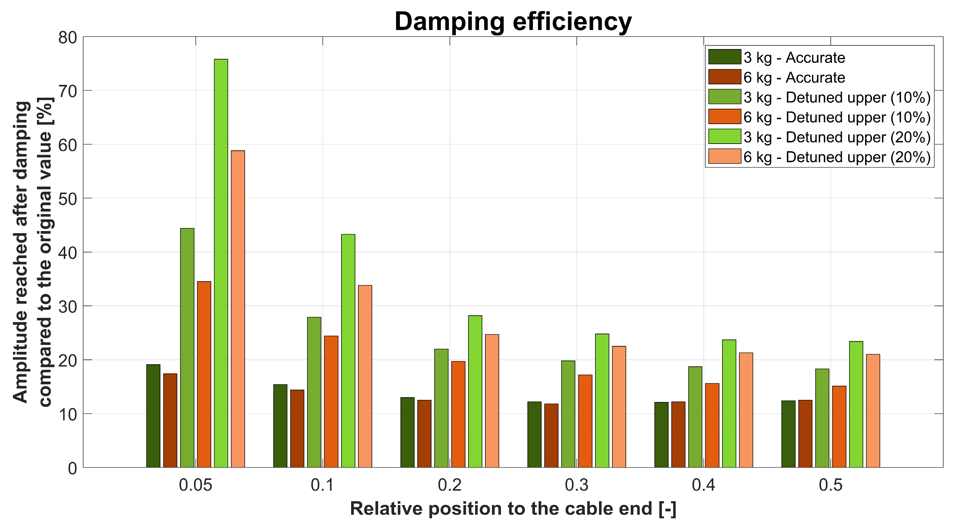
Based on the global model simulations, the relative amplitudes (relative to the amplitude of the unattenuated cable) of the centre of the cable by using different damper configurations are shown in Figure 15. Based on the results, the following design recommendations can be made:
  • In terms of attenuation efficiency, it is preferable to position the attenuator as close as possible to the centre of the cable, but in practice, a positioned element 20% from the cable end can reduce the amplitude to 30%, and this efficiency is not significantly affected by moving the element towards the centre of the cable. Thus, a relative position of ~20% is optimal in terms of attenuation and positioning;
  • Due to the fact that the cable forces are not constant in real life, it is advisable to use a certain detuning to maintain the effectiveness of the attenuator. Figure 15 shows that, depending on the amount of detuning, the attenuator efficiency deteriorates at the design’s natural frequency, but the difference between the accurate and detuned elements decreases as the relative position shifts towards the cable centre. Above the proposed ~20% relative position, even at the extreme of 20% detuning, there is only a 4% difference in amplitude between the exact and the detuned elements;
  • By increasing the masses at the end of the damper, the damping efficiency is improved, which effect is negligible for precisely tuned elements, but the amount of detuning the effect also increases.
As a conclusion, it is suggested to place the dampers in a 20% relative position to reach the optimal configuration; 10% detuning is proposed, as this has a significant effect on the stay cable for a wider range of tension force. The mass of the damper does not play an important role in the optimisation, so it is suggested that 3 kg be used.

4.6. Application

The concepts described herein were used in the design of a footbridge in Budapest, Hungary, connecting an island to the mainland over a smaller branch of the river Danube. The bridge span is 168 m, and it is curved both in horizontal and vertical planes. The bridge deck is supported by 26 pairs of stay cables connected to the pylon. Altogether, 13 cables were damped by the Stockbridge damper type, as shown in Figure 1. Each damper was designed according to the optimal configuration introduced previously (see Figure 16).

5. Local Numerical Model

The numerical simulations on the global model show that it is advisable to have the dampers a small detuning relative to the natural frequency of the stay cable to ensure efficiency over a wider frequency range. In the case of cable attenuation design, the cable frequencies which should be attenuated are typically available as input parameters in practice, e.g., from field measurements. Based on the estimated cable force fluctuation and expected longitudinal position, a target value can be taken for the natural frequency of the damper. However, it is questionable which element parameters and in what way they affect the natural frequency of the element. An advanced solid element model was developed to investigate this problem field.

5.1. Presentation of the Numerical Model

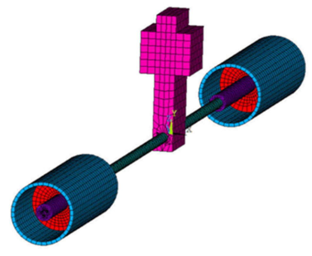
When building the solid element model, the aim was to take into account the geometry of the damper as accurately as possible. Accordingly, the entire messenger cable was made up of three parts with different stiffnesses. The diameter of the free-running cable section itself was taken as the nominal diameter of the cable, and the modulus of elasticity of the steel material assigned to it was defined as a variable parameter as a function of the cable length, using the graph obtained from the results of laboratory measurements (Figure 7). The closing element at the end of the messenger cable has been constructed in two parts, as in reality, with a solid steel external thread part and a section of steel tubular sheathing that attaches to the cable. The adapter element is fixed to the threaded part of the closing element, and to this, the tube section serving as the swinging mass is connected. In the numerical model, 20-node finite elements were used, which allowed the modelling of steel structures with large displacements. The numerical model is built with the length of the messenger cable, with its nominal diameter and the magnitude of the oscillating mass as variable parameters, which allows the effect of varying these parameters on the natural frequency of the cable to be investigated quickly and easily. The model geometry can be seen on Figure 17.
Since the damping element suffers a large deformation due to the effect of the self-weight, the natural frequency was determined by a so-called perturbed modal analysis, which is able to take into account the changed geometry of the structure in the natural frequency calculation. This initial deformation is not only significantly influenced by the three selected design parameters but also by the inclination of the stay cable. An example of this is shown in Figure 18, where a damper with the same parameters under the effect of self-weight is illustrated under different cable inclinations. Thus, the analysis considers the nonlinear effect of large displacements.

5.2. Validation of the Numerical Model

During the experiment, the acceleration of a vibrating centre of mass placed at the end of the cable was measured as a function of time, using “periodic pulse-like excitation” acting on the mass. The natural frequency of the damper could be determined by reading the maximum position of the spectrum generated by Fast Fourier Transformation from the measurement results. By performing a perturbed modal analysis on a damping element with the appropriate parameters for the measurement setup, a numerically determined natural frequency value can be obtained. By comparing the frequency values obtained in the two ways, the numerical model can be validated. Validation was carried out in three different configurations, where the value of the oscillating mass and the diameter of the cable were kept constant at m = 3 kg and d = 12 mm, while the messenger cable length was varied from 200 mm to 400 mm. The maximum difference of the frequencies was less than 1.5%; thus, we concluded that the numerical model tracks the actual structural behaviour well. An example of how the results were compared is shown in Figure 19, where the percentage difference between them is only 1.0%.

6. Results of the Parametric Study

The main objective of parameter estimation is to establish a relationship that can be applied in design practice to estimate the natural frequency of the developed damper by knowing the mass, the messenger cable length, and the nominal diameter.

6.1. Theoretical Background

Yin et al. [33] conducted an analytical investigation to identify the effect of key parameters on the natural frequency of dampers. The paper concluded that the frequency is proportional to certain exponential expressions of the mass, cable length and radius of gyration. As the equations in [33] are highly complex, we now introduce a simplified approximative formula for the first natural frequency of the damper:
f = C · m α · L β · d γ ,
where m is the vibrating mass; L is the messenger cable length; d is the nominal diameter of the cable and C is a constant multiplier. A linear regression analysis is now performed to find the best fit for our data. Equation (2) can be linearised by taking the natural logarithm for both sides
ln f = ln C · m α · L β · d γ   ,
from which, after mathematical transformations
ln f = ln C + α ln m + β ln L + γ ln d   .
The above equation can be written for any damper with different parameter triplets, leading to the following overdetermined system of equations:
1 ln m 1 ln L 1 ln d 1 1 ln m i ln L i ln d i 1 ln m n ln L n ln d n ln C α β γ = ln f 1 ln f i ln f n   .
There are several methods for solving systems of overdetermined linear equations, based on the way in which the error of the solution is minimised. In this case, we solved the system of equations using the Moore–Penrose pseudoinverse (based on minimizing the sum of squares of the residual deviations) according to the following relation (which can be easily calculated using the built-in algorithm of MATLAB [37])
x = ( A T · A ) 1   · A T · b ,
where A is the matrix on the left-hand side of Equation (5) containing the natural logarithm of the simulation parameters; b is the column vector on the right-hand side of the equation containing the natural logarithm of the natural frequencies calculated from the numerical model and x is the vector of unknown parameters.

6.2. Results of Parameter Estimation

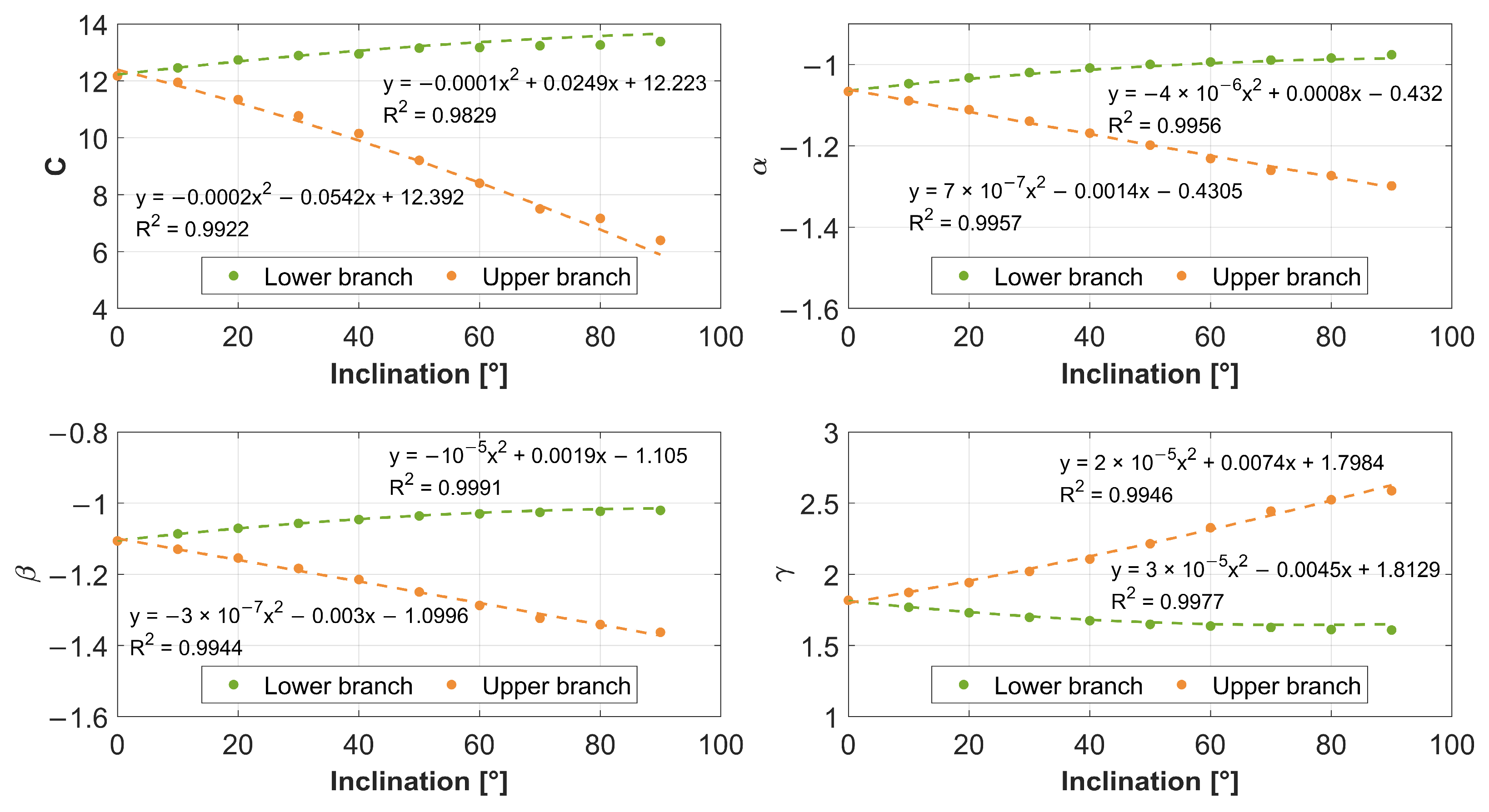
The procedure described above can be applied to an attenuator with a given angle of inclination, separating its lower and upper branches. However, as we have stressed before, the initial shape of the attenuator has a large effect on its natural frequency, and the resulting initial shape is significantly affected by the angle of inclination of the element (i.e., the inclination of the cable to be attenuated). Therefore, to investigate how much and in what way the angle as a parameter influences the specified exponents and the value of C , we performed further numerical simulation series for 0°, 10°, 20°, … 90° inclinations in each case with 15 different sets of parameters. Subsequently, the parameter estimation procedure presented was used to determine the values in question separately for the lower and upper branches of the damper. The results obtained as a function of the angle of inclination are summarised in Figure 20.
The graphs above clearly show that a second-order polynomial can be fitted with a very good approximation to the numerical simulation results for all parameters. Based on the results obtained, a rudimentary design recommendation can be made on how to calculate the natural frequency of the damper for a given set of parameters:
  • In Equation (2), which is effectively “dimensionless”, substitute the parameters ( m , L and d ) of the damping element, in order of k g , m m and m m dimensions.
  • The values of the coefficients and C as a function of the cable inclination angle can be taken from the graphs in Figure 20.
  • Knowing these, the natural frequency can be calculated from the given equation.

6.3. Proposed Formula Reliability Check

To test the reliability and accuracy of the proposed calculation procedure, it is worth examining parameter triples (including the angle of inclination parameter quadruples) that were not used directly to generate the exponents and thus can be considered “independent” data. Based on these principles, we tested three different constructions; the results are summarised in Table 1.
Based on the above results, it can be concluded that the proposed relation and computational procedure reproduce the numerical simulation results, with the maximum difference between the natural frequencies determined by the two methods being no more than 5%. So, the presented method provides a simplified method for quickly estimating the natural frequency of a given parametric damper, eliminating the need for numerical simulation calculations.
It should be noted that the proper design of a Stockbridge damper consists not only of calculating the necessary mass and cable parameters but also of finding the proper materials and connection types, including tolerances, dealing with weather conditions affecting the state of the main structure, wear, etc. These decisions should be made according to the actual possibilities and conditions of the project.

7. Conclusions

In this research, a Stockbridge damper-type damping device was investigated. The main objective was to make suggestions for design practice on which free parameters of the damper affect the efficiency of the element and how, thus facilitating the adaptation of the product to other bridge structures and supporting further developments in this field.
Starting from the models in the literature, first, a global finite element model was constructed to study the system behaviour of the stay cable–damper. Based on the results obtained, the following findings can be formulated to assist the design:
  • In terms of attenuation efficiency, it is preferable to position the attenuator as close as possible to the centre of the cable, but in practice, a positioned element 20% from the cable end can reduce the amplitude to 30%, and this efficiency is not significantly affected by moving the element towards the centre of the cable. Thus, a relative position of ~20% is optimal in terms of attenuation and positioning;
  • Due to the fact that the cable forces are not constant in real life, it is advisable to use a certain detuning to maintain the effectiveness of the attenuator. Figure 15 shows that, depending on the amount of detuning, the attenuator efficiency deteriorates at the design’s natural frequency, but the difference between the accurate and detuned elements decreases as the relative position shifts towards the cable centre. Above the proposed ~20% relative position, even at the extreme of 20% detuning, there is only a 4% difference in amplitude between the exact and the detuned elements;
  • By increasing the masses at the end of the damper, the damping efficiency is improved, which effect is negligible for precisely tuned elements, but the amount of detuning the effect also increases.
After a deeper understanding of the systemic behaviour, the focus was on the local study of the damper. The aim was to establish a relation from which the natural frequency of a damper with given parameters (resonant mass, messenger cable length, nominal diameter, and inclination angle) can be calculated with sufficient accuracy. For this purpose, an advanced body element model was built and validated by laboratory measurements. After that, a multiplicative expression for the frequency was set up, the parameters of which were determined using the Moore–Penrose pseudoinverse as a function of the angle of inclination, using the data from the numerical simulations. By comparing the natural frequency values calculated by the two methods, it was demonstrated that the recommended calculation method can give a reasonable estimate of the natural frequency with a maximum deviation of not more than 5%. The steps of the proposed calculation method are the following:
  • The natural frequency of the damper can be estimated using the following formula:
    f = C · m α · L β · d γ ,
  • In the equation given above, which is effectively “dimensionless”, substitute the parameters ( m , L and d ) of the damping element, in order of k g , m m and m m dimensions.
  • The values of the coefficients and C as a function of the cable inclination angle can be taken from the graphs in Figure 20.
  • Knowing these, the natural frequency can be calculated from the given equation.

Author Contributions

Conceptualisation, B.K. and L.D.; methodology, B.K.; software, A.O.; validation, A.O.; formal analysis, A.O.; investigation, A.O. and B.K.; resources, B.K.; data curation, A.O., P.H.; writing—original draft preparation, A.O.; writing—review and editing, A.O., B.K. and P.H.; visualisation, A.O.; supervision, L.D.; project administration, P.H.; funding acquisition, B.K. and L.D. All authors have read and agreed to the published version of the manuscript.

Funding

The presented research program has been financially supported by the Grant MTA-BME Lendület LP2021-06/2021 “Theory of new generation steel bridges” program of the Hungarian Academy of Sciences and by the ÚNKP-23-2-II-BME-266 Grant of the NKFIH (Hungarian National Research, Development and Innovation Office) within the New National Excellence Program (ÚNKP). Both grants are gratefully acknowledged.

Institutional Review Board Statement

Not applicable.

Informed Consent Statement

Not applicable.

Data Availability Statement

The original contributions presented in the study are included in the article; further inquiries can be directed to the corresponding author.

Acknowledgments

The authors are grateful to the Speciálterv Kft. (especially to Gábor Pál and András Kemenczés) and the A-Híd Zrt (István Medveczki), which companies supported the development process of the presented Stockbridge damper from design and financial point of view, respectively.

Conflicts of Interest

The authors declare no conflicts of interest.

References

  1. Sun, L.; Chen, L.; Huang, H. Stay cable vibration mittigation: A review. Adv. Struct. Eng. 2022, 25, 3368–3404. [Google Scholar] [CrossRef]
  2. SPECIÁLTERV. The Robinson Bridge. 2022. Available online: https://www.specialterv.hu/projects/bridges/robinsonbridge (accessed on 15 April 2024).
  3. Zhou, H.; Sun, L.; Xing, F. Damping of full-scale stay cable with viscous damper: Experiment and analysis. Adv. Struct. Eng. 2016, 17, 265–274. [Google Scholar] [CrossRef]
  4. Zhou, H.; Xiang, N.; Huang, X.; Sun, L.; Xing, F.; Zhou, R. Full-scale test of dampers for stay cable vibration mitigation and improvement measures. Struct. Monit. Maint. 2018, 5, 489–506. [Google Scholar] [CrossRef]
  5. Chen, L.; Sun, L. Laboratory-scale experimental setup for studying cable dampers. J. Eng. Mech. 2014, 141, 04014159. [Google Scholar] [CrossRef]
  6. Chen, L.; Sun, L.; Xu, Y.; Di, F.; Xu, Y.; Wang, L. A comparative study of multi-mode cable vibration control using viscous and viscoelastic dampers through field tests on the Sutong Bridge. Eng. Struct. 2020, 224, 111226. [Google Scholar] [CrossRef]
  7. Sun, L.; Chen, L. Free vibrations of a taut cable with a general viscoelastic damper modeled by fractional derivatives. J. Sound Vib. 2015, 335, 19–33. [Google Scholar] [CrossRef]
  8. Zhao, Y.; Huang, P.; Long, G.; Yuan, Y.; Sun, Y. Influence of Fluid Viscous Damper on the Dynamic Response of Suspension Bridge under Random Traffic Load. Adv. Civ. Eng. 2020, 2020, 1857378. [Google Scholar] [CrossRef]
  9. Liang, L.; Feng, Z.; Xu, Y.; Chen, Z.; Liang, L. Parallel Scheme of Friction Dampers and Viscous Dampers for Girder-End Longitudinal Displacement Control of a Long-Span Suspension Bridge under Operational and Seismic Conditions. Buildings 2023, 13, 412. [Google Scholar] [CrossRef]
  10. Wu, C.; Jing, H.; Feng, Z.; Song, J.; Wan, T.; Chen, Z. Control of longitudinal movement response of suspension bridges induced by passing trains using low-exponent fluid viscous dampers. Structures 2024, 62, 106330. [Google Scholar] [CrossRef]
  11. Wu, C.; He, X.; He, L.; Zhao, X.; Wang, Y.; Li, C.; Yang, Y.; Zhang, X. Improving cable-stayed bridge longitudinal aseismic capability via fluid viscous damper parametric optimization and experimental investigation. Structures 2023, 57, 105199. [Google Scholar] [CrossRef]
  12. Chen, L.; Di, F.; Xu, Y.; Sun, L.; Xu, Y.; Wang, L. Multimode cable vibration control using a viscous-shear damper: Case studies on the Sutong Bridge. Struct. Control Health Monit. 2020, 27, e2536. [Google Scholar] [CrossRef]
  13. Yoneda, M.; Maeda, K. A study on practical estimation method for structural damping of stay cable with damper. In Proceedings of the Canada-Japan Workshop on Bridge Aerodynamics, Ottawa, ON, Canada, 25–27 September 1989; pp. 119–128. [Google Scholar]
  14. Weber, F.; Høgsberg, J.; Krenk, S. Optimal tuning of amplitude proportional coulomb friction damper for maximum cable damping. J. Struct. Eng. 2010, 136, 123–134. [Google Scholar] [CrossRef]
  15. Chen, L.; Sun, L. Calibration of nonlinear damper for shallow cable based on forced vibration analysis. In Proceedings of the EASEC-15, Xi’an, China, 11–13 October 2017; pp. 1852–1859. [Google Scholar]
  16. Chen, L.; Sun, L. Steady-state analysis of cable with nonlinear damper via harmonic balance method for maximizing damping. J. Struct. Eng. 2017, 143, 04016172. [Google Scholar] [CrossRef]
  17. Nakamura, A.; Kasuga, A.; Arai, H. The effects of mechanical dampers on stay cables with high-damping rubber. Const. Build. Mat. 1998, 12, 115–123. [Google Scholar] [CrossRef]
  18. Takano, H.; Ogasawara, M.; Ito, N.; Shimosato, T.; Takeda, K.; Murakami, T. Vibrational damper for cables of the Tsurumi Tsubasa Bridge. J. Wind Eng. Ind. Aerodyn. 1997, 69–71, 807–818. [Google Scholar] [CrossRef]
  19. Su, X.; Kang, H.; Guo, T. Modelling and energy transfer in the coupled nonlinear response of a 1:1 internally resonant cable system with a tuned mass damper. Mech. Syst. Signal Process. 2022, 162, 108058. [Google Scholar] [CrossRef]
  20. Gu, M.; Xiang, H.F.; Chen, A.R. A practical method of passive TMD for suppressing wind-induced vertical buffeting of long-span cable-stayed bridges and its application. J. Wind Eng. Ind. Aerodyn. 1994, 51, 203–213. [Google Scholar] [CrossRef]
  21. Di, F.; Sun, L.; Chen, L. Suppression of vortex-induced high-mode vibrations of a cable-damper system by an additional damper. Eng. Struct. 2021, 242, 112495. [Google Scholar] [CrossRef]
  22. Kaczmarczyk, S.; Iwankiewicz, R. Nonlinear Vibrations of a Cable System with a Tuned Mass Damper under Deterministic and Stochastic Base Excitation. Procedia Eng. 2017, 199, 675–680. [Google Scholar] [CrossRef]
  23. Cu, V.H.; Han, B.; Pham, D.H. Tuned mass-high damping rubber damper on a taut cable. KSCE J. Civ. Eng. 2017, 21, 928–936. [Google Scholar] [CrossRef]
  24. Javidan, M.M.; Assefa, J.D.; Kim, J. Seismic retrofit of low-rise structures using rotational viscoelastic dampers. Structures 2023, 58, 105403. [Google Scholar] [CrossRef]
  25. Javidan, M.M.; Kim, J. Steel hexagonal damper-brace system for efficient seismic protection of structures. Steel Compos. Struct. 2022, 45, 683–695. [Google Scholar] [CrossRef]
  26. Javidan, M.M.; Kim, J. A ductile steel damper-brace for low-damage framed structures. Steel Compos. Struct. 2022, 44, 325–337. [Google Scholar] [CrossRef]
  27. Markiewicz, M. Optimum dynamic characteristics of Stockbridge dampers for dead-end spans. J. Sound Vib. 1995, 188, 243–256. [Google Scholar] [CrossRef]
  28. Vecchiarelli, J.; Currie, I.G.; Havard, D.G. Computational analysis of aeolian conductor vibration with a Stockbridge-type damper. J. Fluids Struct. 2000, 14, 489–509. [Google Scholar] [CrossRef]
  29. Liu, X.; Yang, Y.; Sun, Y.; Zhong, Y.; Zhou, L.; Li, S.; Wu, C. Tuned-mass-damper-inerter performance evaluation and optimal design for transmission line under harmonic excitation. Buildings 2022, 12, 435. [Google Scholar] [CrossRef]
  30. Barry, O.R. Vibration Modelling and Analysis of a Single Conductor with Stockbridge Dampers. Ph.D. Thesis, University of Toronto, Toronto, ON, Canada, 2014. [Google Scholar]
  31. Golebiowska, I.; Dutkiewicz, M. Experimental analysis of efficiency of mass dampers. In Proceedings of the 23rd International Conference Engineering Mechanics, Svratka, Czech Republic, 15–18 May 2017. [Google Scholar]
  32. Wagner, H.; Ramamurti, V.; Sastry, R.; Hartman, K. Dynamic of Stockbridge Dampers. J. Sound Vib. 1973, 30, 207–220. [Google Scholar] [CrossRef]
  33. Yin, Q.; Zhao, J.; Liu, Y.; Zhang, Y. The approximate calculation of the natural frequancies of a Stockbridge type vibration damper and analysis of natual frequencies sensitivity to the structural parameters. Mech. Sci. 2021, 12, 863–873. [Google Scholar] [CrossRef]
  34. Barbieri, N.; Marchi, M.; Mannala, M.; Barbieri, R.; Barbieri, L.; Barbieri, G. Nonlinear dynamic analysis of a Stockbridge damper. Can. J. Civ. Eng. 2018, 46, 828–835. [Google Scholar] [CrossRef]
  35. Foti, F.; Martinelli, L. Hysteretic Behaviour of Stockbridge dampers: Modelling and parameter identification. Math. Probl. Eng. 2018, 2018, 8925121. [Google Scholar] [CrossRef]
  36. ANSYS®, version 19.1; Ansys: Canonsburg, PA, USA, 2018.
  37. MATLAB, version R2023a; MathWorks: Natick, MA, USA, 2023.
Figure 1. Axonometric figure of a Stockbridge damper—design by Speciálterv Kft. [2].
Applmech 05 00046 g001
Figure 2. Messenger cable and the manufactured damper.
Applmech 05 00046 g002
Figure 3. Mechanical models of different damper types—(a) viscous damper, (b) viscous shear damper, (c) friction damper, (d) HDR damper, (e) TMD damper.
Applmech 05 00046 g003
Figure 4. Mode shapes of the 2-degree-of-freedom system: (a) first mode; (b) second mode [33].
Applmech 05 00046 g004
Figure 5. Experimental setup for stiffness measurement.
Applmech 05 00046 g005
Figure 6. Messenger cable characteristic force–displacement diagram.
Applmech 05 00046 g006
Figure 7. Messenger cable substitutes elastic modulus of elasticity as a function of free cable length.
Applmech 05 00046 g007
Figure 8. Measured acceleration–time diagram.
Applmech 05 00046 g008
Figure 9. Attenuation process divided into two stages.
Applmech 05 00046 g009
Figure 10. Global model of stay cable–damper system.
Applmech 05 00046 g010
Figure 11. Displacement response spectra.
Applmech 05 00046 g011
Figure 12. Impact of changes in cable force.
Applmech 05 00046 g012
Figure 13. Effects of the position of the damper.
Applmech 05 00046 g013
Figure 14. Effects of the mass of the damper.
Applmech 05 00046 g014
Figure 15. Damping efficiency at different parameters.
Applmech 05 00046 g015
Figure 16. Stockbridge dampers of a footbridge in Budapest, Hungary.
Applmech 05 00046 g016
Figure 17. Local model of the damper.
Applmech 05 00046 g017
Figure 18. Deformation of a damper under self-weight—(a) 20° inclination, (b) 60° inclination.
Applmech 05 00046 g018
Figure 19. Validation—(a) simulation result, (b) measurement result.
Applmech 05 00046 g019
Figure 20. Parameters as functions of inclination.
Applmech 05 00046 g020
Table 1. Difference between calculated and simulation results.
Natural Frequency [Hz]Relative Deviation [%]
Lower BranchUpper Branch
Damper ParametersAnalyticalNumericalAnalyticalNumericalLower b.Upper b.
φ = 25 ° ,   m = 3   k g
L = 400   m m ,   d = 14   m m
1.2921.2581.1141.1002.721.23
φ = 45 ° ,   m = 6   k g
L = 200   m m ,   d = 14   m m
2.1232.0211.7541.7685.090.77
φ = 65 ° ,   m = 4   k g
L = 350   m m ,   d = 18   m m
2.2492.1551.8311.8364.340.25
Disclaimer/Publisher’s Note: The statements, opinions and data contained in all publications are solely those of the individual author(s) and contributor(s) and not of MDPI and/or the editor(s). MDPI and/or the editor(s) disclaim responsibility for any injury to people or property resulting from any ideas, methods, instructions or products referred to in the content.