1. Introduction
Recently, there has been an exponential increase in mobile data traffic and it is expected to increase by a factor of 1000 over the next decade [
1,
2]. The proliferation of internet- enabled devices such as smartphones, tablets, etc. consuming a large amount of data and emerging bandwidth “hungry” applications and services such as cloud computing, ultra-high definition (UDH) video streaming, augmented and virtual reality (AR and VR) etc. as well as the emergence of the Internet of Things (IoT) are driving this explosion of mobile data traffic, and have put severe pressure on the telecommunication network infrastructure to provide high-capacity (high-speed data rates) links to support emerging cellular systems such as 5G at a low cost [
3,
4]. Due to the limited availability of bandwidth in the sub-6 GHz spectrum throughout the world, the current standards do not support higher data rates.
However, the increasing demand for high-speed broadband data may be addressed by scaling up to the millimeter wave (mm-wave) radio frequency spectrum where the massive amount of unused bandwidth is available [
4,
5]. Although mm-waves are capable of providing huge bandwidth [
6], the propagation characteristics limit their application to a short distance, thus requires numerous base stations (BS) to extend coverage thereby increasing capital (capex) and operational (opex) cost. To facilitate the deployment of fifth-generation (5G) systems, cloud radio access networking (C-RAN) which involves a shift in complexity of expensive equipment and centralizing them at a centralized office (CO) has been proposed to deal with this capex and opex concerns.
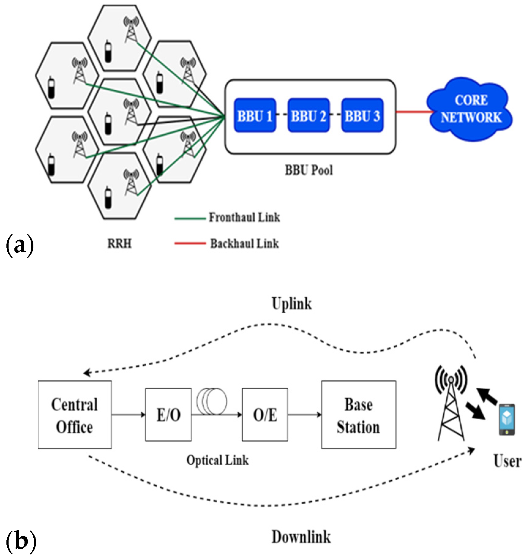
Figure 1a illustrates C-RAN architecture. Also, due to the expensive nature and complexity of generating mm-wave signals, photonic techniques to generate mm-wave signals while facilitating convergence through fiber-wireless integration (Radio over Fiber) have attracted much interest [
7]. To harness the huge bandwidth offered by optical fiber and the flexibility features presented via the wireless, RoF (illustrated in
Figure 1b) based optical-wireless networks have been considered the most promising solution to increase bandwidth, capacity and coverage [
8,
9].
RoF allows the centralization of the baseband processing units (BBU) while simplifying the remote radio heads (RRH) as inexpensive radio access points. The optical transport link between the BBU and the RRH is known as the fronthaul link. As mm-waves suffer various challenges such as high propagation loss, multi-path delay spread effects, scattering losses, etc. multiplexing schemes such as filter bank multi- carrier (FBMC), orthogonal frequency division multiplexing (OFDM), subcarrier multiplexing (SCM), etc. and higher modulation formats such phase shift keying (PSK), quadrature-phase shift keying (Q-PSK) or quadrature amplitude modulation (QAM) have become stringent requirements to achieve high spectral efficiency for 5G systems.
In 5G, many aspects of the current generation mobile networks in terms of speed, bandwidth, energy consumption, latency, etc. will be improved [
10]. Another key aspect is that, 5G will aid to incorporate different technologies like multi-input and multiple out (MIMO), heterogeneous networks, IoT and cognitive radio (CR) [
11]. Currently, various ranges of mm-wave frequencies are being investigated for the physical interface for 5G.
Researchers have shown keen interest in, and conducted extensive research on the frequency spectrums of 28 GHz, 38 GHz, 60 GHz, 75 GHz, 82 GHz, 90 GHz and 110 GHz in realizing a high data rate in Gbits/s to support 5G system. For instance, the authors in [
12] demonstrated the transmission of carrier aggregated OFDM signal over a 28 GHz RoF fronthaul link for data rates of 1.2 and 4.8 Gbits/s over respective bandwidths of 491.5 MHz and 1.96 GHz. In [
13], the authors demonstrated the transmission of five bands of universal filtered (UF)-OFDM on a 28 GHz Vivaldi antenna wireless link for an aggregated total data rate of 4.56 Gbits/s, using 64-QAM modulation, 312 subcarriers and bandwidth of 152 MHz over a 25 km single mode fiber (SMF). Considering a threshold of an acceptable bit error rate (BER) of forward error correction (FEC) with 7% overhead, system performance below the FEC limit for all five bands is achieved.
The authors in [
14] have experimentally demonstrated in 60 GHz mm-wave a spectrally efficient frequency division multiplexing (FDM) RoF system to transmit a data rate of 3.75 Gbits/s over a bandwidth of 1.125 GHz and 250 m multi-mode fiber (MMF) as opposed to OFDM which supported 2.25 Gbits/s over the same bandwidth and fiber length. In [
15], the authors investigated the effect of fiber transmission link parameters for data rates of (10.24, 20.48 and 30.72 Gbits/s) and (9.6, 51.2 and 76.8 Gbits/s) over bandwidths of 16 × 200 MHz and 8 × 1 GHz respectively, and reported for three modulation formats (QPSK, 16-QAM, and 64-QAM) for different fiber length. A 60 GHz mm-wave RoF link using QAM-OFDM modulation and optical coherent detection (OCD) for transmitting 40 Gbits/s data rate over 150 km SMF have been proposed in [
16]. Also, the authors in [
17] proposed and investigated the performance of 40 Gbits/s data rate using 64-QAM OFDM modulation for different number of OFDM subcarriers over 100 km SMF. Although the authors of these papers and several others have successfully investigated and demonstrated by simulation or experiments the realization of high-speed optical links in multi-Gbits/s, the purpose of this paper is to demonstrate by simulation in Optisystem 16 the transmission of 100 Gbits/s data rate over a 2 GHz bandwidth. In this paper, a 28 GHz mm-wave RoF fronthaul system based on OFDM modulation generated by external intensity modulation through the use of Mach–Zehnder (MZM) is proposed. This proposed OFDM-based fronthaul system is investigated for three modulation schemes (16-PSK, 16-QAM, and 64-QAM) for a fiber length of up to 35 km and comparing their performances each for two detection systems; OCD and direct detection (DD). In this paper, the performance of the proposed RoF system is enhanced through a digital signal processing (DSP) compensation scheme based on algorithms to compensate for chromatic dispersion and to correct in-phase and quadrature-phase (IQ-phase) imbalances.
However, the chromatic dispersion and fiber non-linearity effects are compensated for through digital filtering and a digital backpropagation algorithm which are based on a Gram–Schmidt orthogonalization procedure and the inverse non-linear Schrodinger equation, respectively. The throughput performance of the system is evaluated and analyzed in terms of BER and quality factor (QF).
Figure 2. Illustrates the block diagram of the proposed OFDM-RoF based fronthaul system. In this system, a 100 Gbits/s input- data signal is generated and modulated at a 28 GHz carrier frequency. The resulting bandpass signal is modulated over an optical carrier using external intensity modulation by utilizing a
MZM. Filtering and amplification are used to improve the signal quality and transmitted over an optical fiber. OCD or DD are used to detect the signal in the receiver system. A DSP unit is used to compensate for chromatic dispersion, IQ-phase imbalances and fiber non-linearities. The resulting signal is demodulated and the output signal is analysed. The overall system architecture of the proposed system is illustrated in
Figure 3.
The system architecture is divided into 6 parts; The OFDM transmitter system, RF to optical up-conversion (RTO), mobile fronthaul link (MFL), Optical to RF down-conversion (OTR), DSP compensation scheme and the OFDM receiver system.
However, the system architecture can further be divided into 3 main parts where the BBU is made up of the OFDM transmitter system and RTO. The MFL is made up of an optical fiber link and the RRH is made up of the OTR, DSP compensation unit and OFDM receiver system. The rest of the paper is organized as follows. In
Section 1, we discuss the problem and review some related works. The simulation setup of the BBU i.e., OFDM transmitter system and the RTO conversion, are illustrated in
Section 2.
Section 3 and
Section 4 also illustrate the simulation setup of the MFL and RRH systems, respectively. The simulation parameters and results are provided and explained in
Section 5 and finally in
Section 6 we conclude.
2. Baseband Unit (BBU) System
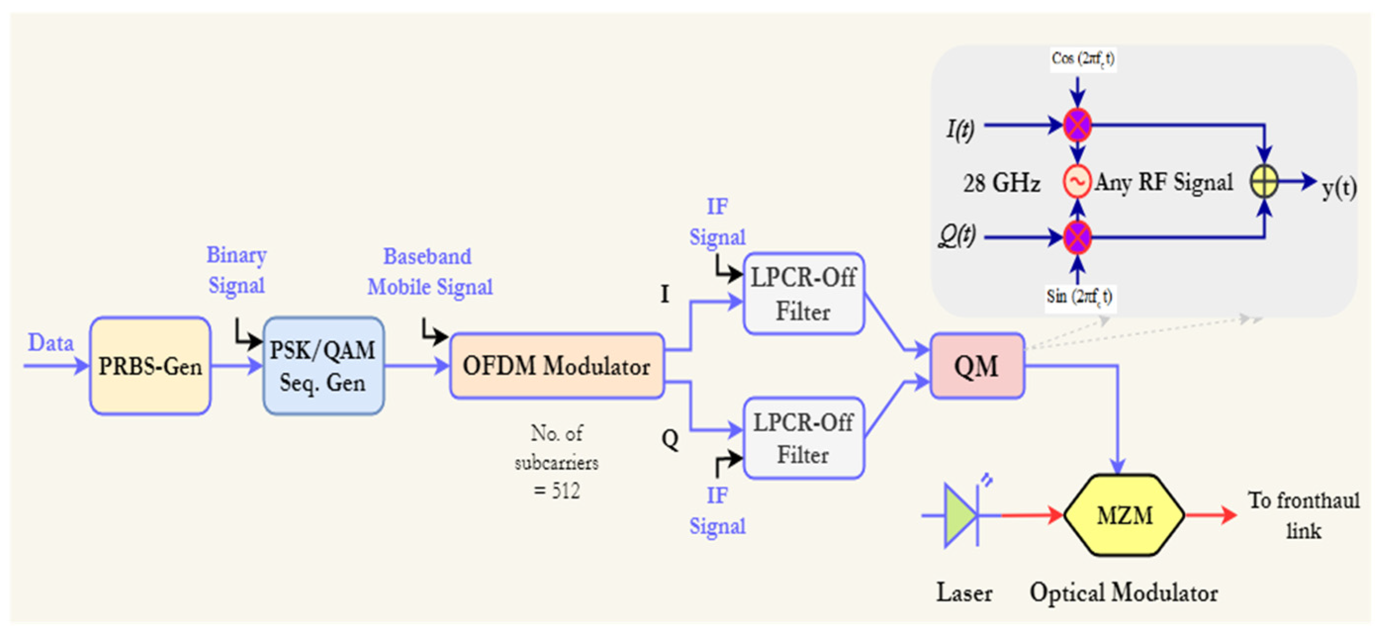
In this section, the BBU system consist of the OFDM transmitter and the RTO converter. The OFDM transmitter system consists of a pseudo-random binary sequence generator (PRBSG) used to generate a stream of binary digits (data) and a PSK or QAM sequence generator is used to generate a multi-bits-per-symbol sequence and to carry the number of bits per symbol. The OFDM technique is used to map the data of the baseband signal, and the OFDM signal generated is filtered by a low-pass cosine roll-off filter (LPCR-off filter) which is used to shape the modulated intermediated frequency (IF) carrier to achieve negligible inter-symbol interference. The resulting modulated OFDM signal is used to modulate the 28 GHz RF carrier generated by using a quadrature modulator (QM). The generated analog signal from the QM is then mapped unto the optical carrier generated from a continuous wave (CW) laser using external intensity modulation as shown in
Figure 4.
In this paper, 512 OFDM subcarriers with an average OFDM power of 15 dBm and 10 cyclic prefix points are set as simulation specification for the OFDM modulator. However, all the individual symbols required for one OFDM symbol period is given as:
Also, the subcarrier frequencies are denoted as;
where,
is the duration of an OFDM symbol. The implementation of the LPCR-Off Filter is based on the following transfer function given as;
where
is the insertion loss, f
c is the filter cutoff frequency, and r
p is the roll-off factor specified as 0.2 and it is the measure of the excess bandwidth of the filter beyond the Nyquist bandwidth of
. The parameter f
1 and f
2 are also given as:
If the excess bandwidth of the filter is denoted as Δf then the roll-off factor, r
p is expressed as:
The QM as shown in
Figure 5 is used to generate any desired RF signal. The local oscillator generates the RF signal such that the I and Q phase components are multiplied by a cosine and sine electrical carriers generated from an electrical wave generator and summing the IQ signal at the output. However, the total output signal is modulated according to:
where,
and Q are the electrical signal, G is the gain, b is the bias, f
c is the carrier frequency, and
ϕc is the phase of the carrier. In this paper, an LiNbO
3 MZM as shown in
Figure 4 is used to externally modulate the RF signal. The behavior of the MZM modulator is expressed as:
where
is the input optical signal,
is the insertion loss, v
1(t) and v
2(t) are the input electrical voltages for the upper and lower modulator arms,
and V
bias2 are the settings of bias voltage 1 and 2 of the modulator, V
πRF and V
πDC are switching modulation voltage and switching bias voltage respectively. ψ is the power splitting ratio of the arm branch written as;
Extinction ratio (ExtRatio) is a parameter linked to the optical power of the external modulator. In this work, an ExtRatio of 60 dB is specified for the
MZM. Also, the CW laser which is used to generate the optical signal at a center frequency of 193.1 THz has a phase noise modeled using the Probability Density Function (PDF) and expressed as;
where Δφ is the phase difference between two successive time instants and dt is the time discretization. However,
has been assumed as a Gaussian random variable with zero mean and variance with Δf the laser line-width.
4. Remote Radio Head (RRH) System
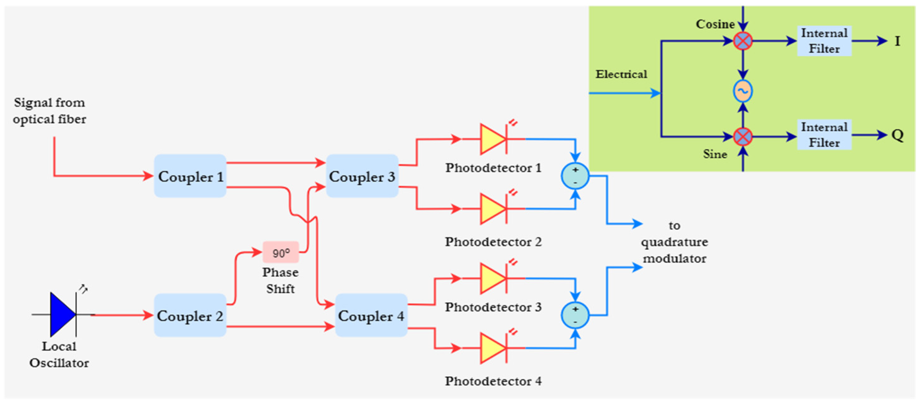
The RRH system is made up of the OTR down-conversion system, DSP compensation unit and an OFDM receiver system. The OTR is an optical detection system consisting of photodetectors. In this paper, OCD or DD is used to implement the OTR system.
Figure 6 and
Figure 7 illustrates the coherent and direct detection systems, respectively. In the OCD system, the incoming optical signal from the fiber coupled with a coherent signal generated from a narrow-linewidth laser with a launch power of −2 dBm is combined using fiber couplers and the signal is detected by two pairs of photodetectors.
The polarization controller ( phase shift) is used to perform mixing of the signals to match the polarization states of the two photodetectors.
The two optical signals in the complex form are expressed as;
where
is the amplitude, ω
o is the carrier frequency and φ
ROS is the phase. However, the optical field associated with the LO is also expressed as;
where A
LO is the amplitude of the local oscillator,
is the frequency of the local oscillator and
is the phase of the local oscillator. Assuming that the two optical fields,
and
are identically polarized, the total optical power incident at the photodetector is given as
.
However, the two equations result in the equation below;
where
and
.
This output signal is demodulated by a quadrature demodulated. The filtered I and Q components are demodulated according to the following expressions respectively;
where,
is the electrical signal at the input,
is that gain,
is the carrier frequency,
is the carrier phase and
is the response time of the internal low pass filter (LPF).
5. In-Phase, Quadrature Imbalance and Non-Linear Dispersion Compensation Based Digital Signal Processing
In this paper, a DSP compensation scheme is implemented in the receiver system to improve the system performance. The DSP scheme is used to compensate for the in-phase and quadrature imbalances which may occur at several points along the transmission path. These imbalances may occur from inappropriate bias voltage settings of the MZM, misalignment of the polarization controller and the photodetector responsivity mismatch.
Figure 8 illustrates the block diagram of the DSP unit in Optisystem. Also, the DSP scheme is used to compensate for chromatic dispersion and non-linearity. For IQ compensation, the DSP unit implements the Gram–Schmidt orthogonalization procedure which results in a new pair of orthogonal signals given as,
and
expressed as:
where,
is the correlation coefficient,
is the ensemble average operator.
and
. For non-linear compensation, the DSP unit implements a digital backpropagation method based on the inverse non-linear Schrodinger equation expressed as;
where
is the complex field of the received signal,
is the differential operator accounting for linear effects (chromatic dispersion and attenuation) and
is the non-linear operator which are given as;
where,
is the attenuation factor,
is the group velocity dispersion and
is the non-linear parameter. In the receiver system, the demodulated IQ signal from the quadrature modulated is first filtered by a LPCR-Off filter before IQ and non-linearity compensation. The resulting signal is demodulated by the OFDM demodulator. The PSK or QAM sequence decoder is finally used to demodulate the OFDM symbol and the BER analyzer is used to estimate the BER and QF.
6. Results
The simulation results in this paper are presented for three modulation formats; 16-PSK, 16-QAM, and 64-QAM and comparing their performance each when either coherent detection or direct detection is implemented in the receiver system. In this paper, we first consider a case without DSP compensation and another case where DSP compensation is implemented. However, the simulation is investigated for an SMF of varying lengths from 5 km up to 35 km.
The performance of this proposed OFDM-based RoF fronthaul system is evaluated using BER and QF.
Table 2 shows the simulation parameters for the proposed system.
Figure 9 illustrates the OFDM signal spectrums for 16-PSK, 16-QAM, and 64-QAM modulation formats at 28 GHz. As shown, the spectrums show peak OFDM power of approximately −51 dBm, −52 dBm, and −5 dBm respectively.
However, we observe a change in the spectrum transmission bandwidth when the modulation type is changed by increasing the number of bits per symbol. The generated OFDM signals when modulated by the MZM modulator will result in a poor modulating optical signal with high harmonic powers levels at the sidebands of the modulating frequency.
However, the optical modulating signals of the three modulation schemes are enhanced through filtering and amplification by using optical filters and amplifiers to improve the signal quality. The improved spectrums and spectrums after the modulating optical signal are transmitted over the optical fiber are shown in
Figure 10. The spectrums after the modulating optical signal are transported over the optical fiber are again shown in
Figure 10 (i.e., spectra of the optical fiber link for 16-PSK, 16-QAM, and 64-QAM).
In this instance, the length of the fiber is 5 km while the system data rate remains 100 Gbits/s. However, we observed that the spectrums show noise power levels of −37 dBm for each of the modulation formats with variations in the signal power for each of the signal lobes.
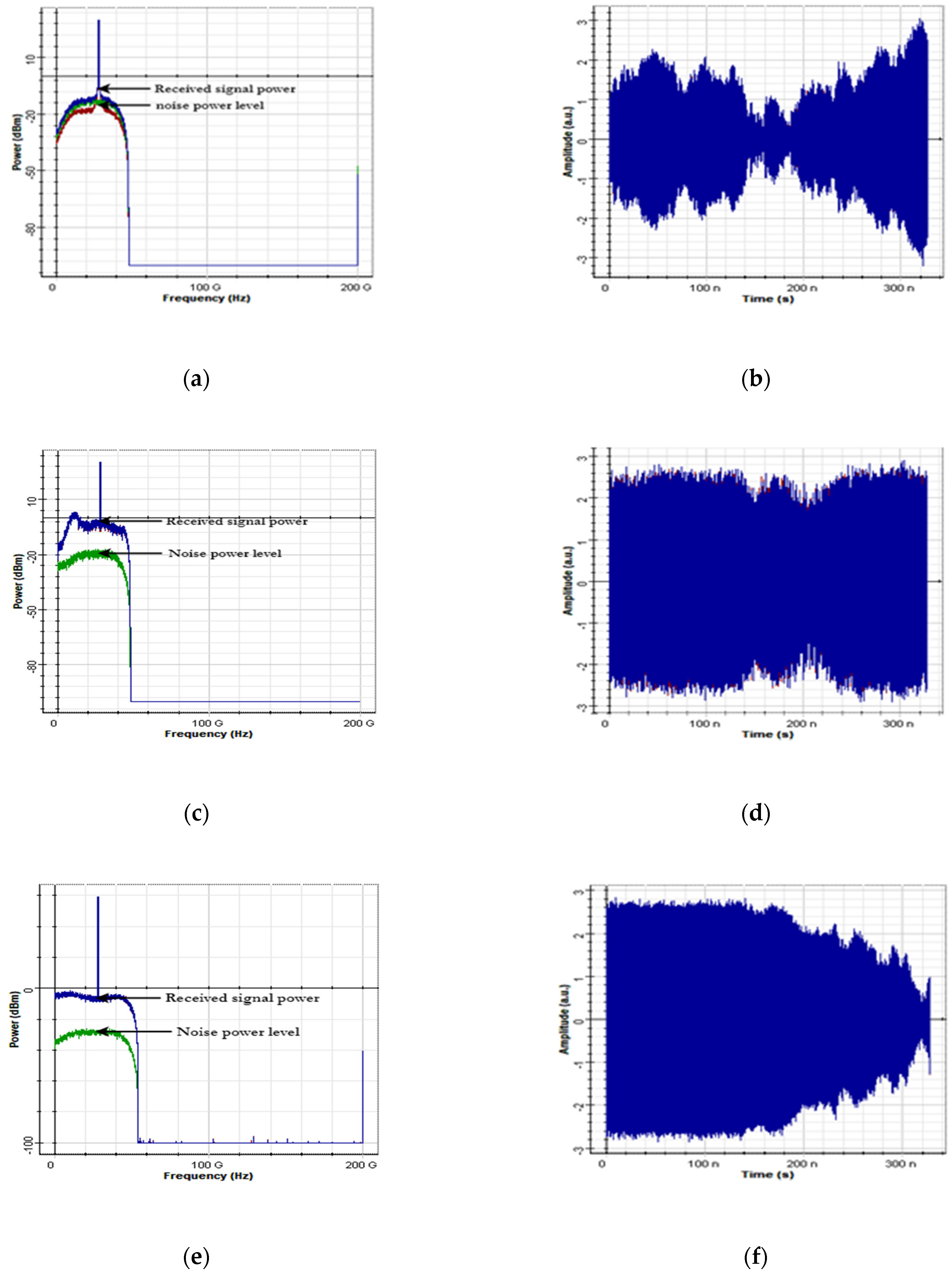
Figure 10 also illustrates the optical spectrum of the CW laser at a center frequency of 193.1 THz. The down-converted signal after detection by the coherent or direct detection receiver in frequency and time domain are shown in
Figure 11 for the three modulation formats.
In
Figure 11a, the amplitude of the signal power is observed to be approximately 8 dBm while the noise power of the system is approximately −10 dBm for 16-PSK format. In
Figure 11c, the spectrum shows a received signal power of approximately −3 dBm and noise power of approximately −18 dBm when the 16-QAM format is used. In
Figure 11e, the received signal power is approximately −6 dBm and noise power of approximately −29 dBm is observed when the 64-QAM format is used. However, from this observation the 64-QAM modulation format shows a higher signal to noise ratio compared to 16-PSK and 16-QAM formats.
Quality Factor and Bit Error Rate Analysis
In this paper, throughput performance in terms of QF and BER are analyzed and compared between employing coherent and direct detection in the receiver system. We first analyze a case for the three modulation formats for a varying fiber length from 5 km to 35 km without using DSP compensation. The second case is analyzed for employing DSP compensation for the same varying fiber length.
In
Table 3 and
Table 4, a summary of the QF and BER for 16-PSK employing coherent and direct detection without using DSP compensation are shown. The two detection systems show excessively poor QF and BER performance values below the threshold of
and 6, respectively, for all the fiber lengths being considered.
In
Table 5 and
Table 6, the two detection systems again show poor QF and BER performance values below the threshold for all the fiber lengths when 16-QAM format is used. However, in
Table 7 the result shows acceptable QF and BER values of 5.78 and
respectively for only 5 km with a received signal power of 25.13 dBm when 64-QAM format is used with coherent detection without employing DSP compensation.
Table 8 shows results for 64-QAM with direct detection without employing DSP compensation.
Figure 12 shows the relationship between the QF, BER and transmission distance for the modulation.
It is observed that the system employing 64-QAM and coherent detection without implementing DSP compensation is the only system feasible for transmitting a data rate of 100 Gbits/s over a transmission distance of 5 km.
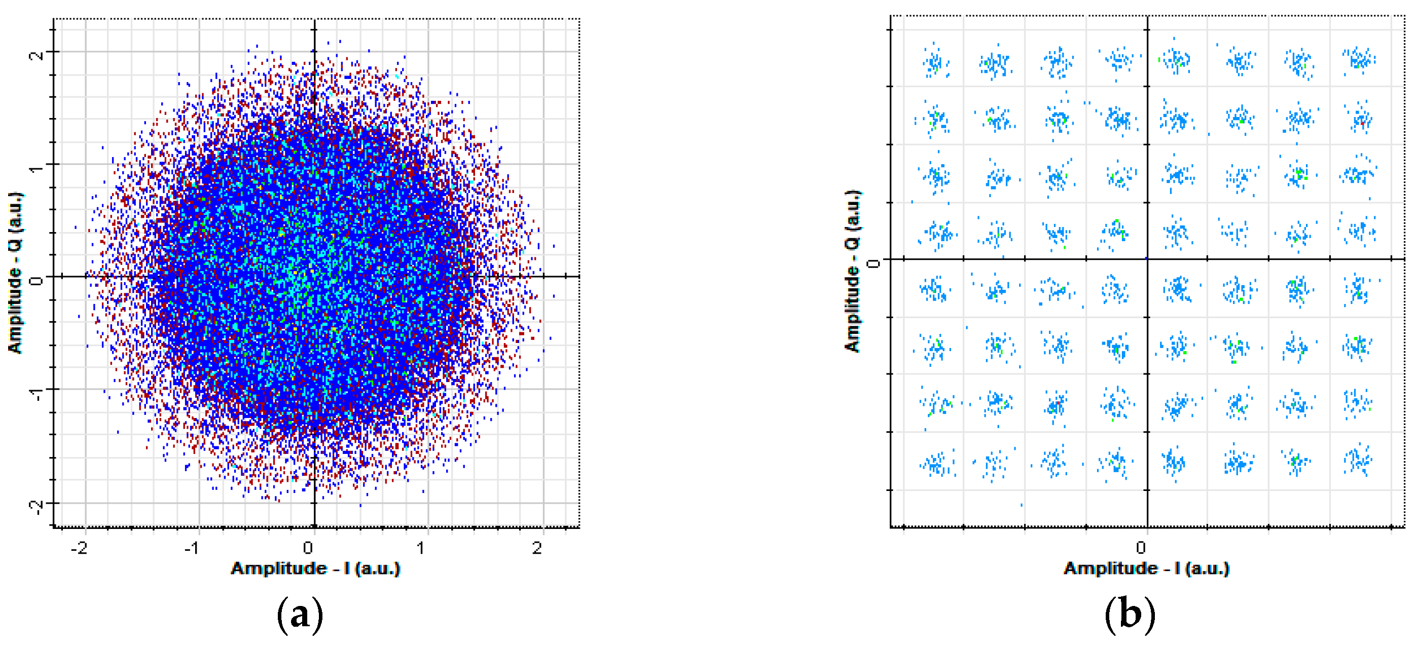
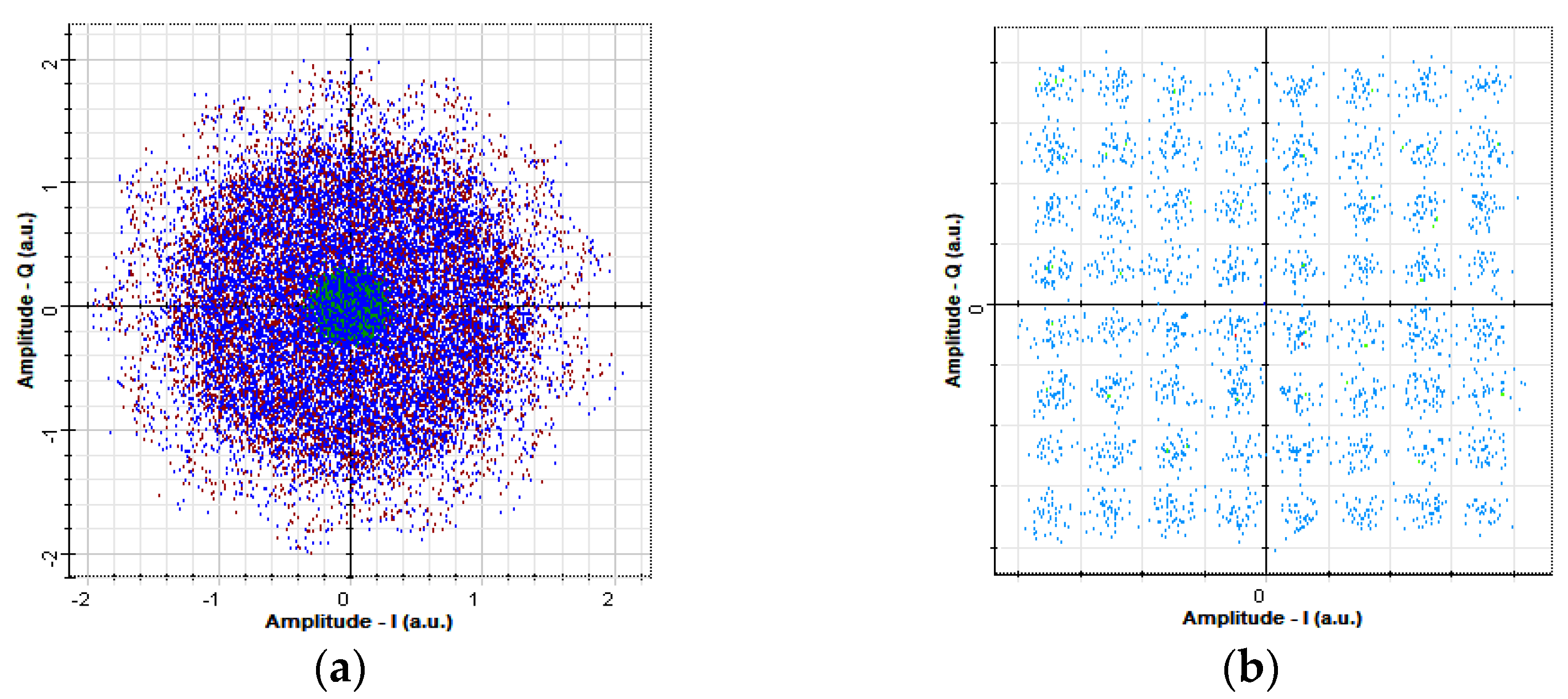
Table 9 shows the QF and BER performance for 64-QAM with coherent detection when DSP compensation is used. The system shows very good QF and BER performance values for all the fiber lengths. The down-converted OFDM signal and the carrier phase estimation is shown in
Figure 13.
However,
Table 10 shows acceptable QF and BER values for a transmission distance up to 10 km when 64-QAM format with direct detection are employed and DSP compensation is used.
Figure 14 shows the constellations of the down-converted OFDM signal and the carrier phase estimation of the symbols at 5 km.
Also, performance metric values for 16-QAM and 16-PSK for both coherent and direct detection for the DSP compensation implementation scenarios are shown in
Table 11,
Table 12,
Table 13 and
Table 14 with varying received signal power at different fiber lengths.
Figure 15 shows the relationship between the QF, BER and the fiber length for all the systems under investigation. Also,
Figure 16 shows the relationship between the received signal power and the fiber length. As shown in
Figure 16a, 64-QAM format with coherent detection employing DSP compensation shows the highest throughput performance in terms of QF and BER. The system QF decrease when the length of the fiber is increased while the BER increases when the length of the fiber is increased. However, the results also show very poor system performance.


