Abstract
In the present era, different allotropes of carbon have been discovered, and graphene is the one among them that has contributed to many breakthroughs in research. It has been considered a promising candidate in the research and academic fields, as well as in industries, over the last decade. It has many properties to be explored, such as an enhanced specific surface area and beneficial thermal and electrical conductivities. Graphene is arranged as a 2D structure by organizing sp2 hybridized C with alternative single and double bonds, providing an extended conjugation combining hexagonal ring structures to form a honeycomb structure. The precious structure and outstanding characteristics are the major reason that modern industry relies heavily on graphene, and it is predominantly applied in electronic devices. Nowadays, lithium-ion batteries (LIBs) foremostly utilize graphene as an anode or a cathode, and are combined with polymers to use them as polymer electrolytes. After three decades of commercialization of the lithium-ion battery, it still leads in consumer electronic society due to its higher energy density, wider operating voltages, low self-discharge, noble high-temperature performance, and fewer maintenance requirements. In this review, we aim to give a brief review of the domination of graphene and its applications in LIBs.
1. Introduction
Modern society is built up by materials, and carbon-based materials are widely held and have a vital role in human civilization. Carbon allotropes are promising candidates for wide applications. Life is impossible without carbon. Carbon is famous for forming many allotropes; graphite, carbon nanotubes, fullerenes, graphene, and diamond are some of the well-known forms of carbon. The structure of some carbon allotropes has been depicted in Figure 1. Compounds based on carbon have been widely used in applications such as environmental, biomedical, energy, photochemical, etc. Carbon is a significant component used in electrochemical applications, such as batteries, supercapacitors, photoelectrochemical water splitting, solar cells, fuel cells, sensors, etc. The advanced large-scale energy storage devices, redox flow cells, are also reliant on carbon-based electrodes [1,2]. Initially, lithium-ion battery research was focused on positive and negative electrodes, wherein the negative electrodes commonly investigated were based on Li metal and lithium alloys [3,4,5]. However, safety concerns are the prime problem, so the focus has mainly been placed on safer anode dendrites, which led to the synthesis of LiC6 in 1965 [6]. In 1967, Besenhard and Eichinger made a discovery that led to the creation of the reversible intercalation of lithium ions from a graphite electrode to form LiC6 [7,8]. At that time, in the absence of appropriate electrolytes to avoid the co-intercalation, graphite was not cast off as a cathode material. In 1978, [9] used polymer electrolytes to overcome the concerns about safety issues, and successfully recognized graphite as an intercalated anode. The important applications of carbon in energy storage devices is authenticated as the commercialized battery is equipped with a graphite anode, which was introduced by Rachid Yazami, for which he was awarded the prestigious Draper Prize in Engineering. Applications for carbon anode materials have been discovered in metal creation, energy stockpiling gadgets like batteries, and supercapacitors. Specifically, graphite and graphene have found successes as anodes, which is not surprising owing to their outstanding electrical properties [10]. Nowadays, the research field is growing very vast, and more contributions have been added to the carbon allotropes by exposing 3D Buckminster fullerene, 2D graphene, and 1D carbon nanotubes (CNTs).
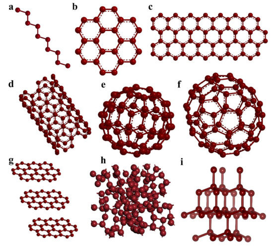
Figure 1.
Structure of various carbon allotropes: (a) carbon chains; (b) polycyclic aromatic hydrocarbon; (c) graphene; (d) carbon nanotube (CNT); (e) C60; (f) C70; (g) graphite; (h) amorphous carbon; and (i) diamond.
In the present day, a wide variety of carbon allotropes has been discovered and studied, among which graphite leads a fantastic role in both the industry and research fields [10]. Since 2004, the discovery of graphene, awarded to Konstantin Novoselov and Andre Geim [11] (with the prestigious Nobel Prize in Physics, 2010) paved a new trend in the research world; this led to an explosion of advancement in energy storage devices, electronic devices, optoelectronic devices, catalysis, and sensors, as well as in the biomedical field [11]. The discovery of graphene is considered the most delightful victory in the discipline of material science, engineering, and technology. The material has many unambiguous physiognomies, such as excellent electronic conductivity, significant specific surface areas, mechanical properties, and elevated thermal stability [12]. Among carbon allotropes, graphene is one of the significant crystalline allotropes; it has a hexagonal, single layer of graphite and the simplest form, with bond distances of 0.142 nm among carbon–carbon single bonds. It has sp2-hybridized carbon atoms, with alternative single and double bonds developing a hexagonal ring structure to form a planar 2D nanosheet structure [13]. Graphene itself occurs in numerous forms, such as nanosheets, nanoribbons, 3D structures, and nanoplates.
Graphene is the most popular carbon allotrope wherein the carbon atoms are bonded to form a unique electronic cloud, which is highly stable and has a size of less than 20 nm. It has been known to exhibit the quantum hall phenomenon. Based on its exceptional characteristics, graphene and its derivatives are gaining a gigantic reputation in every aspect [14]. Graphene can be modified into different forms such as 0D fullerene, 1D CNTs, and 3D graphite, as depicted in Figure 2. In the applied research field, graphene has mostly been used in batteries and sensors. In graphene, all the carbon atoms are sp2 hybridized, leading to an extended π electron cloud all over the structure, which results in super ballistic electronic conductivity [15]. High electronic conductivity can be tuned according to applications by synthesis methods, which aids graphene in a wide variety of applications. The enhanced electronic conductivity makes the allotrope an attractive component in lithium-ion batteries (LIBs).
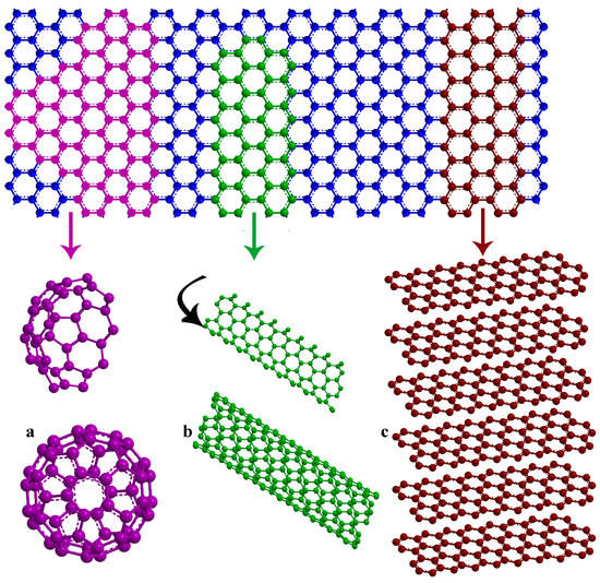
Figure 2.
2D Graphene nanosheets as the basic building units of various carbon allotropes (a) 0D, (b) 1D, and (c) 3D.
Rechargeable LIBs were commercialized in 1991. To date (2021), LIBs are the most reliable and dependent energy storage device, and they have a leading role in the market as well as in research, thanks to the rigorous efforts and hard work of researchers. The first commercialized LIBs relied on the graphite anode and the replacement of the anode, with more conductive graphene is under research. The amazing electron mobility, as well as enhanced surface area, imparted the material to be developed as an inevitable component in energy devices. The premium properties of graphene have paved the way for the researchers all around the world for multipurpose use of the material including its application as components for rechargeable batteries [16]. In the future, the electrochemical enactments of rechargeable batteries will have relied on the advancement in the electrode design as well as its synergistic properties, hence graphene is expected to lead a gigantic role [17,18]. The roadmap of the development of graphene, the timeline of its evolution, is summarized in Figure 3.
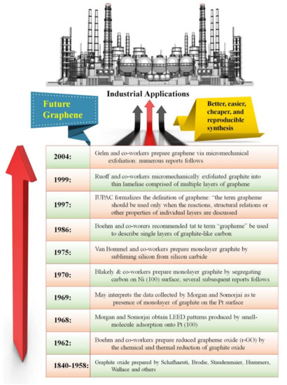
Figure 3.
Roadmap representing the development and future of graphene reproduced from Ref. [19].
2. Graphene; Properties and Synthesis
Graphene comprises sp2 bonded carbon atoms in a single-atom-thick planar sheet to form a hexagonal framework. The astonishing properties of graphene dominate the research world due to the potential applications since its discovery in 2004. The versatile applications including electrochemical performances were tested by various scientists worldwide who concluded that graphene is a promising candidate as an electrode as well as electrolyte for rechargeable batteries. Recently, the major challenge that the future of energy storage devices is focusing on is the commercial-scale synthesis of graphene through ambient methods. In conclusion, future electronic gadgets will be powered by graphene as an electrode as well as electrolyte. Here, the present review provides a precise and brief on the synthesis, properties, application, and the major challenges faced by graphene as active components in LiBs [20].
2.1. Chemical and Physicall Properties of Graphene
Graphene is quite an interesting material for the scientific and industrial community because it is non-toxic, chemically and thermally stable, electrically conductive, and mechanically robust. It is the lightest known material as well as considered to be the building block for the development of other allotropes of carbon, such as one-dimensional carbon nanotubes (CNTs) by rolling up 2D graphene into a tubular form; it also can be wrapped into spherical zero-dimensional bucky balls as well as stacked together to form a three-dimensional (3D) structure of graphite. A virtual demonstration of the evolution of 0D, 1D, and 3D allotropic carbon forms has been demonstrated in Figure 2. On the grounds of the extraordinary electronic properties of graphene, it has been known to be a pseudoconductor with zero electrical bandgap and hence has also been designated as a quasi-metal compound. The charge mobility and carrier concentration in graphene was extensively studied and explained on the basis of Dirac equation. It has a perfect crystalline structure; hence, the energy reduced quasi-particles showed an angular frequency proportional to the wavenumber explained by linear dispersion relation. It is also known for many unusual electronic properties such as ballistic transport electron flow. The graphene is also known to have a pseudospin chirality which was based on the ‘‘Berry phase’’. The material also possess an ambient half-integer quantum Hall effect, as well as a remarkable electronic conductivity in the deficiency of charge carriers. The electronic properties of the graphene inevitably proves its capability as a potential component for upcoming electronic materials, and with a sense of humor, it predicted that the silicon is changed to carbon. Graphene possess the fastest known electronic mobility rate of 15,000 cm2 V−1cm−1. The material also displayed about 200 times enhancement in the mobility of temperature-independent charge carriers (200,000 cm2 V−1S−1) than that of silicon. It also delivered a Fermi velocity of 106 m s−1 in the ambient condition. The graphene also imparts stupendous optical, mechanical, electrochemical, and thermal properties, loftier than other carbonaceous materials. The important properties of graphene in comparison with other allotropes of carbon are enumerated in Table 1. Monolayer graphene is known to possess an excellent mechanical property delivering a Young’s modulus of 1.0 TPa. The stiffness of graphene is obtained to be in the range of 130 Gpa. The monolayer material also displayed an optical transmittance of 97.7% which makes it applicable for transparent electronic gadgets. It also displayed superior thermal conductivity of about 100 times compared with Cu (5000 W m−1K−1). The enhanced theoretical specific surface area (2620 m2 g−1) makes the material exploitable in the area of catalysis and energy storage applications. The inimitable properties of graphene upgraded the material for wide variety of application which is known to out-perform various other carbon allotropes such as CNTs and graphite, as well as metals such as Cu, Pt, etc. in various applications. The tunability in bandgap of the graphene by introduction of dopants and defect states makes it a competitive replacer of several semiconductors for various electronic applications [21].

Table 1.
Physical and electronic properties of different allotropes of carbon. Adapted and reproduced from Ref. [20].
2.2. Various Synthesis Methods Exploited for Preparation of Graphene
Two major modes of synthesis of graphene have been explored to date. The known methods of synthesis can be categorized as the bottom-up and the top-down methods. The bottom-up procedure predominantly incorporates the strategies for the development of graphene epitaxially as well as chemical vapor deposition (CVD). Building the material from atomic-scale can be achieved by CVD, and the epitaxial growth technique can lead to the formation of imperfection-free graphene nanosheets [22]. Thermal reduction, chemical reduction, epitaxial growth, and micromechanical cleavage of graphene oxide (GO) are the main methods used to prepare graphene nanosheets in the top-down method. Among the reported modes of synthesis, the chemical reduction of GO is the most vowing method for the commercialization of graphene. Chemical exfoliation of graphite to graphene oxide can be achieved by several methods such as the Brodie method, Hummer’s method, and Staudenmaier method. GO has a similar layered structure to graphene and in its basal planes has epoxide and hydroxyl groups along with carbonyl and carboxyl groups [23]. These oxidative functional groups are also available at the edges of the GO sheets. The different methods followed from 2004 to now are discussed below, and the process involved in the synthesis is listed in a flow chart and displayed in Figure 4 [24].

Figure 4.
Flow chart representing the synthesis procedure of graphene.
The top-down method mainly takes into account the exfoliation of graphite. The exfoliation of the graphite results in the breakage of Van der Waals’ force of attraction that held the graphite layer together by physical or chemical methods. Significant difficulties in this region incorporate successfully isolating the layers without harming the sheets and forestalling re-agglomeration of the sheets once the layers have been shed. Top-down approaches experience the effects of low yields. Graphite can be created artificially under high-temperature conditions but not mostly appropriate for graphene synthesis due to helpless degrees of graphitization and sporadic morphologies. For bottom-up schemes, undeniable degrees of graphitization should be elevated to create great quality material, so these techniques for the most part require high temperatures. The cycles included are generally basic, albeit the material created can contain more elevated levels of deformities than noticed for hierarchical techniques. In expansion to shaping graphene nanosheets, bottom-up techniques can likewise be utilized to shape enormous region graphene films utilizing development on certain substrates [25]. A schematic illustration of the top-down in addition to bottom-up synthesis technique has been depicted in Figure 5.
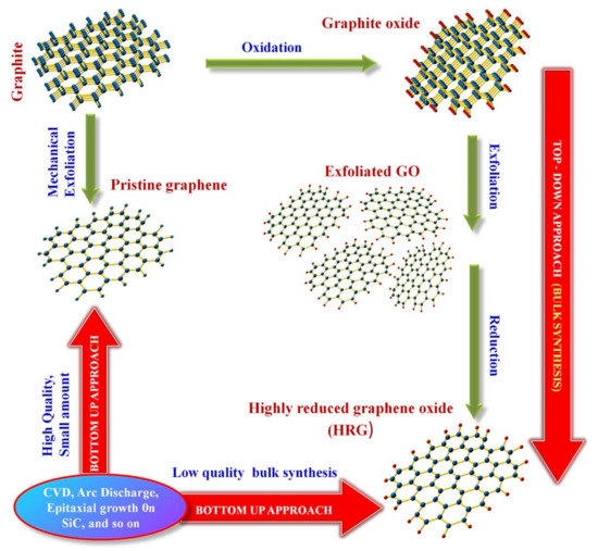
Figure 5.
Pictorial representation of the synthesis method of graphene, categorized by the top-down along with bottom-up techniques. Adapted and reproduced from Ref. [23]. Copyright 2015 Royal Society of Chemistry.
2.2.1. Top-Down Method
The very first method used to isolate monolayer graphene was micromechanical cleavage. In this method, the graphite was exfoliated to separate the layer using adhesive tape. Hence, this method is widely known as the Scotch tape or the Peel-off method [25]. It is the principal technique used for the synthesis of graphene, offering better electronic conductivity compared with other synthesis methods. This strategy permits solid and simple preparation however experiences a low yield [21,26].
Chemical exfoliation is referred to as the finest method. In this method, graphene is produced from bulk graphite and graphite intercalation compounds. Graphene oxides were produced in 1860 by Brodie, Hummers, and Staudenmaier methods. Mainly, two steps are involved in this process, the formation of intercalation compounds and the exfoliation by sonification. GO is commonly synthesized by the Hummers method, the most popular chemical exfoliation method. The exfoliation of GO can be achieved by an oxidative technique of graphite separating the interlayers using strongest oxidizing agents such as NaNO3 in H2SO4/H3PO4 and KMnO4 followed by ultrasonication in a dimethyl formamide (DMF) water mixture (typically 9:1 v/v) mixture to produce single-layer graphene oxide. Thermal exfoliation and reduction of graphite oxide similarly produce good-quality graphene [25,27].
2.2.2. Bottom-Up Method
On account of the epitaxial development method, at elevated temperatures, graphene is grown on silicon carbide (SiC) as well as metals substrates such as ruthenium, platinum, etc., under ultrahigh vacuum. The proposed method is capable of developing graphene with reduced defect states. However, the high-vacuum conditions enhance the expense of manufacture and yield a lower amount of product compared with other methods [25]. The development of graphene on SiC also favored the sublimation of silicon along with the formation of graphite with excess number of carbon atoms at elevated temperatures exceeding 1000 °C and ultra-high vacuum (UHV) conditions. Growth of graphene in the argon atmosphere or the presence of minor amounts of di-silane has been exposed to decrease the rate of silicon sublimation, leading to higher temperatures to be castoff and which produce higher-quality graphene. Preferential Si sublimation can be prompted by pulsed electron irradiation [25,28].
Chemical vapor deposition (CVD): In this method, graphene was formed by the disintegration of hydrocarbons followed by deposition of graphene from atomic-scale at elevated temperatures on metal oxide such as alumina (Al2O3) and magnesia (MgO) as well as metal substrates such as nickel, platinum, and copper. The CVD method mainly depends on the substrates and produces high-quality graphene; however, there is a significant expense and moderately low yield. On the other hand, this methodology has an extraordinary potential that can be added for additional improvement. Mainly, the peeling of graphitic materials is the key procedure and includes oxidation, intercalation, shedding of graphene subordinates, such as graphite, CNTs, expandable graphite, graphite oxide, graphite intercalation compounds, and graphite fluoride. The reduction of graphite oxide with a minimum about of expense could yield a huge amount of rGO with high processability. The major growth parameters taken into account while using the CVD method are the substrate quality, C/H ratio, pressure, temperature, and oxygen on the substrate surface influences the graphene synthesis [25,28].
3. Lithium-Ion Battery: A Brief Overview
In comparison to the battery chemistries, LIBs are still ruling the portable gadget market attributable to their specific characteristics such as prodigious energy density, border operating voltage, good temperature performances, low self-discharging capacity, long cycling life, sustainability, and minimal maintenance requirement. Sony Japan commercialized LIBs for the first time in 1991, and the application levels are extended to more different fields including defense, aerospace, and automobile industries, and renewable energy integration. The performance of these rechargeable batteries greatly relies on the physiochemical properties of both anodes as well as cathodes. Additionally, it is affected by the electrode structure and synthesis routes. Schematic illustration of a typical LIB have been demonstrated in Figure 6. The commercial LIBs consist of carbon (graphite) based active material as anode and lithium metal oxide-based active material in cathode along with a carbonate-based organic electrolyte along with inorganic lithium salts for lithium ions to move back and forth easily [27].

Figure 6.
Schematic demonstration of typical LIB comprising of graphite as anode, lithium iron phosphate as cathode, and lithium salt-based electrolyte.
4. Graphene as Components in LIBs
In the current scenario, the LIBs industry has been mainly ruled by graphite. Graphite is commercially used as the anode in rechargeable LIBs due to the low cost, low volume change, great Coulombic efficiency, stable cycling performance, and conductivity as well as availability. However, graphite possesses a theoretical specific capacity of 372 mAh g−1, comparatively much lower; it also shows a poor rate of performance. The graphite anode becomes confined to meet the current practical sense of LIBs requirement due to the limited lithium storage sites. To overcome the issues of graphite, graphene becomes the most relevant component [29,30]. As described earlier, the LIBs comprise three major parts, anode, cathode, and electrolytes. The major advantage of graphene is the ability of the material to augment the performance of all these components, thereby boosting the overall performance of the battery.
4.1. Pristine Graphene and Graphene Composites as Anodes in LIBs
LIBs are widely utilized in versatile hardware, for example in phones, laptops, tablets, computerized cameras, and so forth, and are accepted to be promising decisions as energy-successful and climate well-disposed gadgets. For the most part, LIBs are made out of anodes, electrolytes, and cathodes. During the charging of LIBs, the de-lithiation from the positive electrode traverse along the electrolyte and embed into the negative electrode. Further re-energizing, finished with the Li-particle inclusion/extraction measure in the cathodes, the idea of the two-terminal materials is pivotal to the performance of LIBs. The present terminal materials utilized in LIBs exist Li intercalation mixtures such as graphite as negative electrode and lithium cobalt oxide (LiCoO2 and LCO) as positive electrode material, as they displayed effective reversible charging/releasing under intercalation possibilities. Even if graphite electrode displayed better Coulombic efficiency, it fell behind in higher Li stockpiling limit (hypothetical worth: 372 mAh g−1) as a viable negative electrode material in the upgraded power stockpiling gadgets. Consequently, a much higher accused stockpiling limit of promising cyclability and rate capability of negative electrodes in LIB research has gained serious consideration. The presence of graphene-based negative electrode with its nano structural advancement is to be utilized as an anode in r-LIBs. A current commercial negative electrode, graphite can be replaced by graphene, which is considered to enhance the performance of the device without incorporation of harmful chemicals such as lithium. The graphene-based anodes may consist of pristine graphene nanosheets, graphene nanosheets composite with carbon nanomaterials (CNT, fullerene, etc.), metals, chalcogenides, and doped graphene nanosheets.
4.1.1. Pristine Graphene as Anode for LIBs
Graphene is also specified as graphene nanosheets (GNS) and is widely explored as the negative electrodes for energy storage devices. The theoretical specific capacity of graphene is reported to be 744 mAh g−1 which is twofold than that of the 3D graphite (372 mAh g−1) [31]. Initial reports on graphene nanosheets based anode for LIBs were reported by Honma et al. [32] in 2008, wherein they compared the performance of graphite with graphene nanosheets, graphene nanosheets composites with CNT, and fullerene. The investigation of the reversible capacity of various anodes at 0.05 A g−1 revealed that graphite anode delivered a capacitance of 340 mAh g−1 whereas GNS, GNS/C60, and GNS/CNT anodes delivered a reversible capacity of 540, 784, and 730 mAh g−1, respectively, which confirms that graphene nanosheets offer almost double intercalation of lithium ions than graphite anodes [32]. The charge–discharge profiles and cycling stability have been depicted in Figure 7.
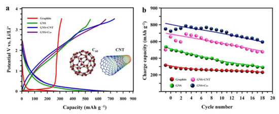
Figure 7.
Charge–discharge profiles and cycle stability of the graphite, graphene (GNS), GNS + carbon nanotube (CNT), and GNS + Fullerene (C60); (a) charge/discharge curves at 0.05 A g−1, (b) comparison of cycling performance. Adapted and reproduced with permission from [32]. Copyright 2008 American Chemical Society.
A modification in the result was introduced by Song et al. [33] (2009) wherein graphene nanosheets were prepared by Staudenmaier’s method. The anode was fabricated with GNSs/acetylene black/poly (vinylidene difluoride) (PVdF) 80:10:10 wt.% and the cell studies of the anode were investigated in the electrolytic medium of 1 M LiPF6 in EC: DMC (1:1 v/v). The anodes retained an electrochemical stability voltage ranging from 0 to 3.5 V. The initial cycling performance of the cell revealed a charge/discharge capacity of 1233 and 672 mAh g−1, respectively, at a current density of 0.2 mA cm2. After prolonged cycling exceeding to 30 cycles, it displayed a reversible capacity of 502 mAh g−1 [33] comparable to the previous report [33]. A reasonable advancement in the performance of GNS anode was reported in 2013 by Hassoun et al. [34]. In the study, GNS was fabricated by the exfoliation of graphite by the wet chemical method followed by the fabrication of the full cell with GNS/PVdF/carbon super P in the ratio 80:15:5 coated on the copper foil as anode and cathode as LiNi0.5Mn1.5O4 coated on aluminum foil. The electrolytic medium was the same as that of the previous report [33]. The cell displayed a stabilized capacity of 600 mAh g−1 dropped from an initial performance of 2000 mAh g−1 [34] (Figure 8a) as well as a working voltage of ~0.9 V, which was substantially higher than the previously reported performances. The comparison of charge–discharge voltage profiles of the first two cycles of GNS/LNMO cell depicted in Figure 8b shows the drop in performance due to lithiation of the electrode [34].

Figure 8.
Cycling performance of GNS as anode; (a) charge–discharge profiles of GNS at 149 mA g−1, (b) charge/discharge profiles of the GNS resulting by the pre-cycling process at 74 mAh g−1 in lithium and LNMO half cells. Adapted and reproduced with permission from [34]. Copyright 2013 Royal Society of Chemistry.
In 2013, Sun et al. [35] reported structurally modified GNS as a negative electrode for LIBs. The report revealed the structures have an evident task in the enhancement of storage competence of the negative electrode. In relevance to the explanation, three different types of GNSs were fabricated with variable morphologies. For the synthesis of two of the morphologies, modified Hummer’s method was adopted by varying the stirring time, and another sample was prepared by autoclaving the second GNS fabricated by modified Hummer’s method using urea and was labeled as GNS I, II, and III, respectively [35]. The morphologies of corresponding samples have been depicted in Figure 9 [35]. These GNSs synthesized via modified Hummer’s method resulted in the formation of thin translucent nanosheets with more extent of exfoliation was evident for GNS II where additional stirring was provided during the synthesis. The morphology of the hydrothermally treated GNS samples showed much reduction in the size which can be associated with the enhancement in the extent of exfoliation as evident from Figure 9c,d [35].
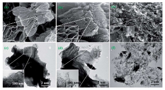
Figure 9.
Morphological analysis of graphene nanosheets (GNS) synthesized in varying conditions; SEM images of (a) GNS-I, (b) GNS-II, and I GNS-III; TEM images of (c) GNS-I, (d) GNS-II,(e) SEM image of GNS-III; TEM image of GNS-II and (f) GNS-III. Adapted and reproduced with permission from Ref. [35]. Copyright 2013 Royal Society of Chemistry.
The cell studies of the structurally modified GNS samples were conducted in a coin cell with copper foil as current collector on which the active material (GNS) was coated with PVdF binder in the ratio of 90:10. The electrolyte employed was 1 M LiPF6 in EC/DEC/EMC in equi-volume ratio. The initial charge capacities of GNS-I, GNS-II, and GNS-III were obtained at 1275, 861, and 1233 mAh g−1, and the discharge capacity was obtained at 925, 418, and 2561 mAh g−1, respectively [35]. On prolonged cycling, the capacity decreases, which is ascribed to the formation of the SEI layer. After 99 cycles, GNS I, II, and III exhibited a discharge capacity of ~270, 400, and 690 mAh g−1, respectively [35] as depicted in Figure 10a. The Coulombic efficiency of the samples has been displayed in Figure 10b, which indicates that the GNS I and II showed variation in the efficiency whereas GNS III maintained the performance almost equivalent to 100%. Overall, the performance of the GNS anode has relied on the extent of exfoliation, the more the extent of exfoliation efficiency will be the anode [35]. In 2020, Mu et al. [36] further added vertical graphene sheets support (not exclusively) the lithium-ion transport rate due to its inherent high electrical conductivity, however likewise can altogether diminish convolution of lithium-particle transport due to its exceptionally particular lithium-particle inclusion ways. Into equal parts cells, the vertical graphene sheets/graphite can persevere through 3000 cycles in 3 min of charge time per cycle. All the more strikingly, a full cell with vertical graphene sheets/graphite anode and LiFePO4 cathode shows an elevated energy density of around 312 Wh kg−1 in 10 min of charge time per cycle at 4 C, showing that the vertical graphene sheets/graphite anode has the capacity of outrageously quick charging while at the same time keeping up high energy density.

Figure 10.
Cycling stability of graphene nanosheets synthesized by varying the conditions as anodes tested in the half cell; (a) Coulombic efficiency against cycle numbers of various GNSs, (b) cycling stability of various GNSs at 100 mA g−1. Adapted and reproduced with permission from Ref. [35]. Copyright 2013 Royal Society of Chemistry.
4.1.2. Doped-Graphene as Anode for LIBs
Conductivity and electrochemical performance of 2D graphene sheets were profoundly enhanced by doping with nitrogen, boron, phosphorous, etc. The method is quite similar to N-doping and P-doping in semiconductors. N-doped graphene was developed by CVD [37] technique as well as arc discharge technique [38]. The first principle studies revealed that the conductivity of graphene was substantially enhanced with the introduction of nitrogen or boron atom to the lattice [38]. The bond length of the N-C bond was almost the same, whereas the B-C bond length was slightly more than that of the carbon–carbon single bond length in pristine graphene. An analogues’ property was also observed in the case of interlayer spacing; N doped GNS showed slight enhancement in the spacing, whereas B doped GNS with considerable enhancement in the spacing [38]. Theoretical studies of doped graphene as anode material in LIBs were conducted by Zhou et al. in 2011 [37]. The first principle studies revealed that the Li desorption and adsorption undergoes faster in N and B-doped GNS. The activation barrier of the delithiation process of N-doped graphene is relatively inferior to that of graphene. Successively, the authentication in the theoretical results was investigated by Sun et al. [39] developing an investigational proof. The N-doped graphene was synthesized by chemical exfoliation using modified Hummer’s method forming graphite oxide followed by annealing at 1050 °C under a nitrogen atmosphere. Thus, received samples were further annealed in the occurrence of ammonia gas (NH3) leading to the materialization of N-doped GNS. The morphological analysis of the GNS and N-doped GNS has been depicted in Figure 11 [39]. The reversible discharge capacity after 100 cycles of the GNS and N-doped GNS resulted in 269 and 452 mAh g−1, respectively. Discharge capacity of N-doped GNS was found to increase up to 500 cycles and remained almost constant in the range of 684 mAh g−1 [39].
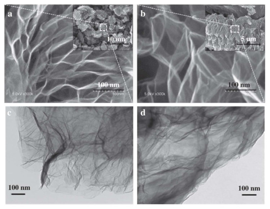
Figure 11.
Electron micrographs of GNS and N-GNS; SEM images (a) GNS and (b) N-GNS; TEM (c) GNS and (d) N-GNS. Adapted and reproduced with permission from Ref. [39]. Copyright 2011 Elsevier.
Properties of N-doped GNS were enhanced by the addition of additives such as Fe3C [40], SiO2 [41], Li3VO4 [42], MoS2 [43], etc. Fe–Fe3C/N-doped GNS binary composite was synthesized by pyrolysis process of MIL-100 (Fe) (porous metal-organic framework) which delivered a discharge performance of 607 mAh g−1 at 1000 mA g−1 extending the cycle stability to 100 cycles [40]. SiO2/GNS composite was fabricated by the hydrothermal method [41]. The sample with 1:0.5 of GNS: SiO2 showed a considerable enhancement in the performance, and the analysis at current densities ranging from 100, 200, 500, 1000, 2000, to 5000 mA g−1 resulted in discharge capacity of 1052, 866, 670, 536, 415, and 272 mAh g−1 [41], respectively. The results revealed superior properties for SiO2/GNS composite as anode material in LIBs. Li3VO4/GNS composite was synthesized by the hydrothermal method which displayed an initial charge–discharge capacities of 429 and 550 mAh g−1, respectively, at a current density of 0.15 A g−1 [42]. On prolonged cycling, the performance was increased and was sustained after 100 cycles at 476 and 478 mAh g−1, respectively [42]. The MoS2/GNS nanocomposite was prepared by hydrothermal method followed by thermal treatment. The samples dispensed enhanced performance with a reversible capacity of 1151 mAh g− 1 at 0.1 A g−1. The cycle stability was retained up to 92.6% even after 600 cycles [43].
Recently, N-GNS with MoS2 (N-GRs/MoS2) have been reported by Xiao et al. [43]. The graphene oxide was prepared by spray drying technique from graphene oxide nanosheets (GONs), which were sonographically dispersed in deionized water. To the dispersed solution, L-cysteine along with sodium molybdate mixture in deionized water was added dropwise followed by stirring [43]. The solution mixture was then subjected to hydrothermal treatment for 12 h. The resultant product was repeatedly washed with deionized water followed by freeze-drying. The final product was obtained after annealing the dry samples at 800 °C for 2 h in an Ar atmosphere (denoted as N-GRs/MoS2). For comparison, pristine MoS2, N-doped graphene ribbons (N-GRs), and N-doped graphene nanosheets/MoS2 (N-GNs/MoS2) were also synthesized. A schematic illustration of the synthesis of N-GRs/MoS2 and N-GNs/MoS2 has been demonstrated in Figure 12 [43]. The performance of the material as the anode in LIBs was tested using Li half-cell and N-GRs/MoS2//LiFePO4 full cell configurations. The anode was coated on aluminum foil by mixing sample/conductive material (Super P)/polyvinylidene difluoride binder (PVdF) in the ratio of 8:1:1 [43]. The electrolyte used for the study was the 1 M solution of LiPF6 in carbonate mixtures of ethylene carbonate (EC)/dimethyl carbonate (DMC)/ethyl methyl carbonate (EMC) in the ratio of 1:1:1. The performance of the cell with varying current densities is displayed in Figure 12b, evidently showing the enhanced discharge capacity of the anode of about 499 mAh g−1 even at an elevated current density (8.0 A g−1) [43]. Moreover, samples also displayed better cycling as shown in Figure 12c. The cycling was extended up to 200 cycles at 0.5 A g−1, where N-GRs/MoS2, N-GNs/MoS2, and pristine MoS2 anodes delivered a discharge performance of 925, 389, and 311 mAh g−1, respectively, wherein N-GRs/MoS2 displayed a capacity retention of 102%, which is 2.38 and 2.98% greater than that of N-GNs/MoS2 and pristine MoS2, respectively [43]. The results reveal the enhanced and sustained performance of N-GRs/MoS2 anodes-based LIBs.

Figure 12.
Nitrogen-doped graphene nanoribbons and nanosheets composite with MoS2; (a) schematic illustration on the preparation of N-doped graphene ribbons/molybdenum sulfide (N-GRs/MoS2) and N-doped graphene nanosheets/molybdenum sulfide (N-GNs/MoS2) composites, (b) cycle stability of N-GRs/MoS2 from 0.1 to 8.0 A g−1 and (c) cycling performance comparison of N-GRs/MoS2, N-GNs/MoS2, and pure MoS2 at the current density of 0.5 A g−1. Adapted and reproduced with permission from Ref. [43]. Copyright 2021 Elsevier.
4.1.3. Nanocomposites Based on Graphene as Anode for LIBs
Nanocomposites based on graphene are polyphase materials where the graphene stays as a network stage. The majority of the composite materials grown at any point formed by the incorporation of metal oxide, sulfide, and metal nanoparticles into graphene. Wu et al. [20] demonstrated the prevalence (as far as electrochemical highlights) of graphene/metal oxides composites, for example, moored, wrapped, typified, layered, sandwiched, and blended models, (Figure 13) compared with that of pristine compound [44]. Graphene-based inorganic composites of several metal chalcogenides were widely explored. Co3O4 [45], silicon [46,47], sulfur [48], Fe3O4 [48], SnO2 [49], CuO [50], TiO2 [51], MoS2 [52], MoO2 [53], MgO [54], Fe2Mo3O8 [55], Co2Mo3O8 [56], Sb2S3 [57], Fe2O3 [58,59], ZnMo3O8 [60], and graphene eggshells in-graphene foam [61] were also reported as composite anode for LIBs. The possibility of graphene composites as components in LIB is an alluring one due to their fantastic electrochemical exhibitions. Herein, the sum up of graphene based composites has been investigated at this point just to stamp their superlative electrochemical highlights came about due to creative designing.
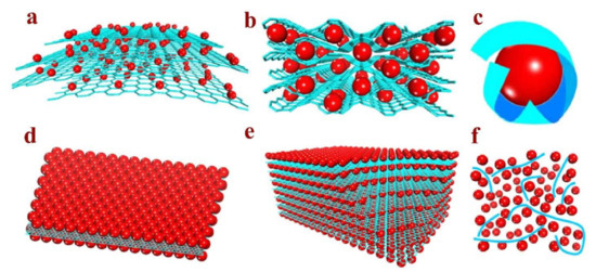
Figure 13.
Schematic representation of metal oxide/graphene composite models: (a) surface anchored model, (b) wrapped model, (c) encapsulated model, (d) sandwich model, (e) layered model, and (f) mixed model. In the structures, red balls represent metal oxide particles and the blue sheets represent 2D graphene sheets. Adapted and reproduced with permission from Ref. [20]. Copyright 2012 Elsevier.
Fe2O3/Graphene Based Composite as Anode for LIBs
Iron oxide (Fe2O3) is widely explored as an anode material owing to the ease of intercalation/deintercalation of the lithium ions in the lattice of the metal oxide. The low cost, reduced toxicity, and ease of fabrication make the anode a widely accepted metal oxide for application [62,63,64,65,66]. The Fe2O3 based anodes are known to intercalate six lithium ions in the lattice-based on Equation (1) [58].
Fe2O3 + 6 Li+ + 6 e− → 2 Fe + 3 Li2O
Wang et al. [67] investigated the graphene/Fe2O3 nanocomposite prepared by reduction of the graphite oxide by hydrogen reduction method at 500 °C which was incorporated in the Fe2O3 synthesized by in situ hydrothermal treatment. The electrochemical performance of the nanocomposites was compared with the pristine Fe2O3 micro particles prepared by the same technique. The electrochemical performance of composites was analyzed by fabricating electrode CR2430 coin cell assembled with composite material as anode vs. Li+/Li reference electrode. The charge–discharge performance of the cell was analyzed 0.005 V to 3.0 V vs. Li+/Li reference electrode. Graphene/Fe2O3 cells delivered an initial discharge capacity of 1800 mAh g−1 at 160 mA g−1 and a charge capacity of 1420 mAh g−1 at the same condition. Comparing the performance of Graphene/Fe2O3 with pristine graphene and Fe2O3 electrodes at the same current density after 100 cycles displayed a 660 mAh g−1, which was much higher than that of the pristine cells (Graphene electrode-550 mAh g−1 and Fe2O3 450 mAh g−1. A similar study conducted by Li et al. [68] Graphene/Fe2O3 composites were prepared by solution mixing of Fe2O3 nanoparticles with graphene oxide synthesized by modified Hummer’s method by ultra-sonication followed by freeze-drying technique. The electrochemical studies of coin cells fabricated with composite as anode vs. lithium metal revealed an initial charge discharge capacity of 2550 and 1551 mAh g−1, respectively, at 0.1 C cycled between 0.01 to 2.5 V. Zhu et al. [58] reported a simple two-step reaction for the synthesis of rGO/Fe2O3 nanocomposite by homogeneous precipitation of FeCl3 in a suspension of graphene oxide platelets with urea, with subsequent decrease in the graphene oxide with hydrazine by microwave technique to yield rGO platelets decorated with Fe2O3 nanoparticles [58]. The scattered Fe2O3 nanoparticles on rGO nanoplatelets offered an enhanced electrical conductivity. The charge and discharge capacities of rGO/Fe2O3 composite revealed the enhanced performance of 1227 and 1693 mAh g−1. The specific capacity of rGO/Fe2O3 has enhanced considerably than the pristine RG-O and Fe2O3 confirming the synergistic effect of rGO and Fe2O3 on the improvement of electrochemical performance.
Copper Oxide/Graphene Composites as Anode for LIBs
Copper oxide is one of the widely explored anode materials for LIBs. The eco-friendly nature of the metal oxide, along with superior theoretical capacitance (674 mAh g−1) as well as the availability of the material makes it a highly attractive candidate as the anode in rechargeable batteries. Several reports on exploring CuO as the anode in LIBs have been reported so far [69,70,71]. The lithium insertion in the CuO anode causes volume expansion leading to a decrease in the cyclability of the batteries is considered to be a major drawback of these anodes. Hence, to enhance the cycling stability of CuO, carbon allotropes are added as a composite material. Among carbon allotropes, graphene is the most prominent. Lithiation and de-lithiation of the CuO anode, analyzed by transmission electron microscopy, revealed the formation of Li2O in the CuO matrix by Equation (2) [72]. The schematic illustration of in situ analysis of TEM of LIB is depicted in Figure 14a. Figure 14b reveals the TEM image of the composite CuO/graphene electrode. Based on the morphological variation, an ion-conducting pathway has been proposed in Figure 14b. The size of the CuO nanoparticles anchored on graphene resulted in a volumetric expansion of during the lithiation and delithiation process of the anode. Figure 14h displays a focused image of the lithiated CuO nanoparticles, evidently displaying that the surfaces, as well as the edges of the composite electrodes, were coated with thin shells of Li2O which was further confirmed by Figure 14i. The variation in size of the CuO composite during lithiation and delithiation process is demonstrated in Figure 14j [72].
CuO + 2 Li+ + 2e− → Cu + Li2O
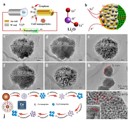
Figure 14.
Morphological images of the changes occurring in pristine CuO/graphene electrode on charge–discharge cycling in a nano-LIB; (a) Illustration of the electrochemical setup for in situ TEM imaging, (b) schematic representation of the reaction front in a single CuO particle and the transport pathway for Li+ ions and electrons; TEM image of (c) the pristine CuO nanoparticle, (d) the first lithiation product, (e) delithiated CuO nanoparticle, (f) the second lithiated CuO, (g) delithiated CuO nanoparticle (h) HRTEM image recorded from a lithiated CuO nanoparticle, (i) lithiated CuO nanoparticles, (red circles indicate the formation of Cu grains and the inset represents high resolution images, and (j) the schematic illustration of the variation in size of the CuO on lithiation/delithiation process. Adapted and reproduced with permission from Ref. [72]. Copyright 2015 American Chemical Society.
Liu et al. [73] reported the fabrication of free-standing and flexible CuO nanosheets (NSs)/reduced graphene oxide (r-GO) hybrid lamellar paper via simple vacuum filtration method followed by hydrothermal reduction of the products. The surface charge of GO being the negative the positively charged copper oxide are decorated on the GO surface as depicted in Figure 15. The morphological analysis of the composite membrane confirms the decorated structure (Figure 15). The electrochemical performance of the composite was analyzed in three different mass ratios of CuO NSs to r-GO (2:1, 1:1, 1:2) which was directly employed as the working electrode, and Li metal foil was used as the reference electrode. The working electrode was used in pristine form without the binder and conductive carbon. The studies revealed that CuO NSs/rGO (1:1) delivered an enhanced discharge specific capacity of 736.8 mA h g−1 at a current density of 67 mA g−1 [73].
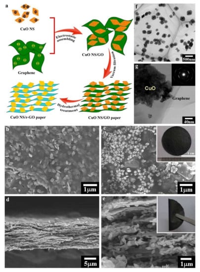
Figure 15.
(a) Schematic representation of the synthesis of flexible free-standing CuO nanosheets (NSs) with graphene oxide (GO)/reduced graphene oxide (r-GO) hybrid lamellar paper via simple vacuum filtration method followed by hydrothermal reduction (CuO NSs/GO and CuO NSs/r-GO paper); Morphological analysis of the sample, top-view SEM images (b) CuO NSs/GO and (c) CuO NSs/r-GO paper, the inset in c is a digital photograph of CuO NSs/rGO paper with a diameter of ca. 19 mm; Cross-section SEM images of (d,e) CuO NSs/r-GO paper, the inset in e is a digital photograph shows good flexibility (the inset in e), (f,g) TEM images of the CuO NSs/r-GO paper, inset of (g) is electron diffraction pattern. Adapted and reproduced with permission from Ref. [73]. Copyright 2013 American Chemical Society.
Molybdenum Chalcogenide/Graphene Composites as Anodes for LIBs
Molybdenum composites are one of the most widely explored two-dimensional materials due to their properties similar to that of graphene. Hence, molybdenum-based chalcogenides such as molybdenum oxide, molybdenum sulfide, etc., are widely investigated as anodes composited with graphene for enhancing the anodic properties in LIBs lithium-ion batteries. Chang et al. [52] investigated layered MoS2/graphene composites revealed the most elevated explicit limit of 1571 mAh g−1 at a current density of 100 mA g−1 estimated from MoS2/G (1:2) on account of its round 3D morphology (Figure 16a). The intercalation of the Li+ ions was eased which was evident from the cyclic stability and rate capability delivered by the cell studies as depicted in Figure 16c,d. In 2014, Choi et al. [74] arranged folded graphene/MoO3 composite by shower pyrolysis, ensuing tempering at 300 °C [74]. They closed its performance as improved explicit limit (1490 mAh g−1), higher Coulombic efficiency, better cyclic security, and expanded rate ability in correlation with uncovered MoO3 powders (Figure 16). Petnikota et al. [53] found the intercalation of Li-ion and explained the synthesis of exfoliated graphene oxide/MoO2 composites as anode materials through a modest solid-state graphenothermal reduction method. The results revealed intercalation mechanism is best for steady-state capacity during the cycling for the reason of superfluous graphene and stability window even in the operating voltage of 0.005−3.0 V and MoO2 undergoes conversion below 0.8 V. Almodavar et al. [75] studied hexagonal molybdenum trioxide (h-MoO3) micro rods and their composites with graphite, graphene, and graphene oxide. The h-MoO3/GO terminals convey a striking explicit limit of 789 mAh g−1 after 100 cycles at a high current density of 1000 mA g−1, while h-MoO3-graphene cathodes show a great steadiness at extremely high current densities, with a specific capacity limit exceeding 665 and 490 mAh g−1 at 2000 and 3000 mA g−1, respectively. EIS estimations and SEM-EDX of the cycled terminals uncover that the consistently scattered graphene and GO layers increase the structural stability of the composites and make a conductive organization that guarantees compelling ambipolar dispersion of electrons and Li+ particles, bringing about a huge electrochemical limit and rate execution at raised current densities. These outcomes grow the possible uses of h-MoO3 and their composites towards LIBs, making them ready for future upgrades.
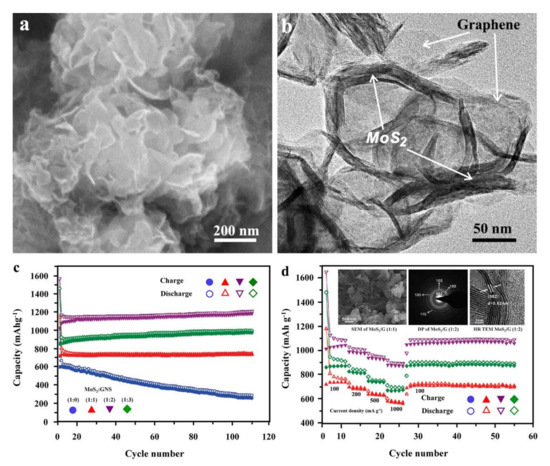
Figure 16.
Morphology and electrochemical properties of layered MoS2/graphene composites (MoS2/G) synthesized in variable ratios; Morphology of layered MoS2/graphene composites (MoS2/G) synthesized in 1:2 ratio (a) SEM image, (b) TEM image; electrochemical properties of layered MoS2/graphene composites (MoS2/G) synthesized in variable ratios, (c) cycling behavior of MoS2, MoS2/G (1:1), MoS2/G (1:2), and MoS2/G (1:3) after annealing in H2/N2 at 800 °C for 2 h at a current density of 100 mA g−1; (d) Rate capability of MoS2/G samples at different current densities (inset provided the SEM image, SAED pattern and HRTEM images of MoS2/G composites). Adapted and reproduced with permission from Ref. [52]. Copyright 2011 American Chemical Society.
Titanium Oxide/Graphene Composites as Anode for LIBs
Titanium oxide, otherwise known as titania, is a wide bandgap semiconductor material. The optical band gap of titania is reported to be 3.1 eV. Titania crystalizes in three forms, namely anatase, rutile, and brookite, out of which rutile form is stable in room temperature conditions and is widely formed when titania is synthesized in the bulk form, whereas anatase and brookite are metastable forms stabilized in lower size regimes. Titania has been widely explored as anode material in LIBs [76,77,78,79,80]. However, the performance of the anode can be enhanced by incorporating various nanomaterials in the metal oxide as a composite. Graphene is one of the major composites added to titania to improve the performance of the anode in LIBs. The TiO2/graphene, as well as TiO2/reduced graphene oxide (rGO) composites, are widely explored in this area. These composites are mostly synthesized by reacting graphene oxide (GO) and TiO2 nanoparticles through hydrothermal reaction [74], UV photocatalytic reduction of GO in the presence of TiO2 [81], and even synthesized by dispersing graphene as sol-gel along with titania precursor [82] A schematic illustration on the formation of TiO2/graphene composite with titanium hydroxide precursor is depicted in Figure 17.
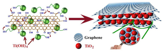
Figure 17.
Schematic representation of the mechanism of the formation of the TiO2/graphene nanocomposite, wherein Ti(OH)4 reacts with functional groups of GO sheets leading to the reaction of oxygen atoms with titanium precursor to form graphene/TiO2 nanocomposites. Adapted and reproduced with permission from Ref. [83]. Copyright 2014 Elsevier.
Qiu et al. [83] reported mesoporous TiO2/graphene composite was synthesized by titania oxysulfate (TiOSO4) as TiO2 precursor which was hydrothermally composited with graphene oxide (GO) by a one-step hydrothermal route. The electrochemical studies of the composite were analyzed by fabricating working electrodes with TiO2/G, acetylene black, and binder (polytetrafluoroethylene, PTFE) at a weight ratio of 70:20:10 and lithium metal as reference electrode, with electrolyte medium of 1 M LiPF6 in ethylene carbonate/dimethyl carbonate (EC/DMC, v/v 1:1) mixture. The alteration in discharge capacity at variable current densities (500 to 5000 mA g−1) investigated revealed a discharge capacity of 206.7 mAh g−1 at 500 mA g−1 after the 10th cycle which was further diminished to 190.9, 179.1, 169.5, 160.8, and 141.7 mAh g−1 at the current densities of 1000, 2000, 3000, 4000, and 5000 mA g−1, respectively. The same group also reported the synthesis of TiO2/ graphene composites by the photocatalytic method [81]. For the same, GO was synthesized by modified Hummer’s method and titania (anatase) was synthesized by hydrothermal method from titanium butoxide precursor. TiO2/graphene composite was prepared by homogeneously mixing GO (0.04 g in ethanol) with TiO2 (25 mL) solution (2% w/v) in an ultrasonic bath followed by UV irradiation under 1000-W xenon lamp with prolonged stirring (2−5 h). The resultant solution was then filtered and rinsed with deionized water, and the resultant composite obtained was dried in a vacuum oven at 60 °C for 12 h. Thus, the obtained TiO2/graphene composite was used for electrochemical analysis as an anode in LIBs. The reversible discharge capacity of TiO2-rGO, TiO2-GO, and TiO2 was 310, 220, and 150 mAh g−1, respectively, which was much higher than the previous report [81]. The transport properties of TiO2/graphene composites were reported by Lam et al. [84]. The TiO2 with tiny subunits enclosed in highly conductive graphene oxide nanosheets, which possess a highly porous network structure facile the diffusion of the electrolyte facilitating the lithium–ion intercalation and enhancing the electronic conductivity to the external circuit, as depicted in Figure 18.
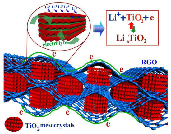
Figure 18.
Schematic representation of the transport path of lithium ions and electrons in the theTiO2/graphene hybrids where TiO2 with tiny subunits enclosed in highly conductive graphene oxide nanosheet (TGR) hybrids. Adapted and reproduced with permission from Ref. [84]. Copyright 2015 Nature.
Graphene/Silicon Composites as Anode for LIBs
Si nanoparticles have been widely investigated as anode in LIBs for their most elevated known hypothetical charge limit (4200 mAh g−1) and poor release potential (~0.5 V versus Li/Li+) [85,86]. Similarly, its powerful application in LIB cannot be executed in light of its gigantic volumetric extension (~270%) from electrochemical responses [87]. Subsequently, hardly any more works have been investigated to reveal graphene fuse as framework stage along with the nanoparticles based on Si to beat these inadequacies [87,88]. For instance, Lee et al. [47] reported the synthesis of Si nanoparticles incorporated graphene sheet (Si/GS) by sandwiching the 3D graphite network with well-dispersed Si nanoparticles inside the graphene layers. The fabricated anode material is capable of exhibiting a greater capacity limit of ~2200 mAh g−1 after 50 cycles with a capacity retention of ~1500 mAh g−1 even after 200 cycles. The cross-section of the electrode before and after 200 cycles has been given in Figure 19. The expansion of the electrode is visible from the given images. Modification of Si/GS structure was reported by Kim et al. They have used the strategy of covering the gel by ex situ carbon and carbonization to form thermally decreased 2D planer Si/GS structure and settled three-dimensional Si/graphene sheet/carbon (Si/GS/C) nanocomposite having enough inner void space [86]. The gathering disclosed a prevalent explicit limit ~1350 mAh g−1 and good cyclic security (~600 mAh g−1 after 200 cycles) as compared with Si/GS in the premise of extended cycle exhibitions.

Figure 19.
Morphological analysis of a cross-section of Si/graphene sheet/carbon (Si/GS/C)-S@Gr before and after cycling; (a) before and (b) after cycling for 200 cycles. Adapted and reproduced with permission from Ref. [86]. Copyright 2016 authors.
In 2017, Yi et al. [89] displayed a compelling plan and blend of SiC/G nanocomposite where nanoparticles of SiC are homogeneously implanted in GNS. They proposed a simpler SiC/graphene anode combination with improved electrochemistry through Li+ ion dispersion. The report estimated a reversible limit of 1044 mAh g−1 at a current density of 100 mA g−1 and an extraordinary electrochemical stability of 230 mAh g−1 even after 1000 cycles at 1 Ag−1 (Figure 20). Another recent work was proposed by Shi et al. [90]. They have explored CVD method to synthesize vertical graphene-epitomized SiO microparticles (d-SiO@vG) (Figure 20). The interconnected vertical graphene–SiO anodes showed good cycle stability of 1600 mAh g−1 with about 93% of retention in capacity even after 100 cycles. Nanostructure correction of Si/graphene nanocomposite by surficial carbon covering additionally gained a lot of consideration from researchers. Li et al. [91] revealed in 2013 a carbon-covered Si nanoparticle/ graphene composite (Si@C/G) thermal annealing of the freeze-dried mixture of Si nanoparticles, sucrose, and GO. Here, the carbon-covered Si nanoparticles disperse simultaneously with GO, which delivers cycling stability of 1410 mAh g−1 at a current density of 500 mA g−1 after 100 cycles. Ma et al. [92] revealed in 2017 an upgrade which resulted in carbon nanofibers interlaced graphene/silicon (G/Si@CFs) structure. Graphene oxide (GO) was synthesized by Hummer’s method followed by spray drying. GO powder was then calcined at a high temperature of 1000 °C under nitrogen atmosphere protection to form micron-sized spherical particles with curved and loose-packed graphene sheets (GS). Si nanoparticles were then deposited onto the surface of GS to form a G/Si composite by a chemical vapor deposition (CVD) at 550 °C [92]. Silane was used as Si precursor and hydrogen was used as the carrying gas. Synthesized G/Si particles were followed by mechanical mixing in DMF solution of polyacrylonitrile (PAN), the resultant medium was subjected to electrospinning process, PAN compounded G/Si particles and PAN nanofibers composite film was prepared. The annealing at 800 °C in Ar gas caused the carbonization of PAN to form a composite film of a high conductive carbon nanofibers network and the carbon-coated G/Si particles. A schematic illustration of the same has been depicted in Figure 20A [92]. In this investigation, at first, pre-arranged Si/graphene composite was covered by exceptionally conductive carbon nanofibers networks is evident from the SEM and transmission electron microscopic (TEM) images as given in Figure 20 [87]. The resulting electrochemical highlights of this structure are a beginning release limit of 1792.1 mAh g−1, 86.5% limit maintenance after 200 cycles, and high rate execution esteemed 543 mAh g−1 limit at the pace of 1000 mA g−1. Subsequently, successful Si/graphene-based nanocomposite configuration may be those constructions where graphene stays as a non-stop conductive organization to convey familiar sections of Li-ions to dynamic materials and support the volume change of Si-based materials. Thus, Si-based nanoparticles disseminated homogeneously with high surface regions ought to be filled in as host destinations of lithiation and delithiation. It has been, as of the time of writing, accepted that the nanosized metallic oxides, sulfides, and carbides are better than their mass partners [93].

Figure 20.
(A) Schematic illustration on the synthesis of process of the G/Si@CFs composites (a) SEM image of G/Si particles, (b,c) HRTEM image of G/Si particles, (d) low magnification SEM image of G/Si@CFs, and (e) high magnification SEM image of G/Si@CFs. Adapted and reproduced with permission from Ref. [92]. Copyright 2017 Nature.
4.2. Graphene as Cathodes for LIBs
Different types of graphene-based composites have been reported as cathodes in LIBs. Due to its 2D versatility, graphene can easily connect dynamically to metal oxide surfaces. Pristine graphene, doped graphene, graphene composites such as graphene/metal phosphates, graphene/metal silicates, graphene/metal chalcogenides, etc., are some of the most commonly reported graphene composite cathodes for LIBs. Among them, olivine phosphate (Li2MPO4) and silicate (Li2MSiO4) (M = Fe, Mn, and Co) have the benefits of minimal expense, good electrochemical performance, high stability, and so forth, explored widely as cathode materials in LIBs [94,95].
4.2.1. Pristine Graphene as Cathodes for LIBs
Graphene as an anode was widely explored in LIBs, but the same as a potential candidate for cathode was less investigated. The carbon-based electrodes are capable of the formation of oxocarbon salt (Li2C6O6) reversibly enabling the development of new generation sustainable as well as eco-friendly energy storage devices [96,97,98]. In 2013, Sung et al. [99] reported the development of reduced graphene oxide which serves as free-standing cathodes for LIBs. The GO synthesized by modified Hummer’s method was subsequently thermally reduced to rGO under Ar/H2 atmosphere. Thus, prepared rGO was then mixed with CTAB (cetyltrimethylammonium bromide) by stirring and sonication technique. The mixture was centrifuged to collect the supernatant liquid followed by filtration in the AAO membrane to prepare free-standing rGO films [99]. The electrochemical studies of the membrane were conducted by assembling coin cells with rGO, lithium metal and Celgard 2600 as the working electrode, counter electrode, and separator, respectively. The electrolyte medium employed was the 1 M solution of LiPF6 in ethylene carbonate/dimethyl carbonate (EC/DMC (1:1) v/v). rGO 15 (the sample with carbon to oxygen ratio 15) reveals an initial discharge capacity of ∼125 mAh g−1, and within five cycles, it is stabilized at 110−115 mAh g−1 (Figure 21). Xiong et al. [100] reported enhancement in the electrochemical properties of the rGO on an increase in oxygen-containing functional groups. The rGO was synthesized from GO by thermal reduction procedure at different annealing temperatures and times. The cell studies were conducted by fabricating the electrode in the active material, conductive carbon, and PVdF (binder) in NMP in the ratio of 80:10:10 and coin cells were fabricated similar to that of the previous procedure. The sample, annealed for 1 min at 950 °C, revealed an initial discharge capacity of 163 mAh g−1, enhanced up to 220 mAh g−1 at 50 mA g−1 [100].
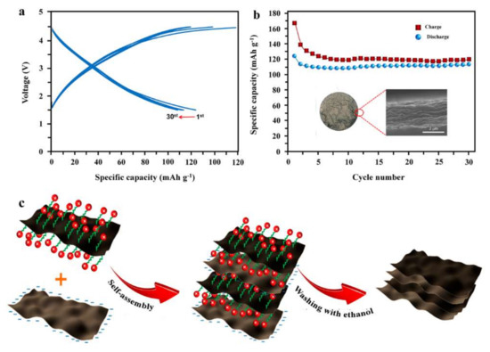
Figure 21.
The performances of rGO15 films at 0.137 A g−1 for 30 cycles; (a) charge–discharge curves, (b) cyclability of rGO15, and (c) schematic illustration of the synthesis of rGO electrode. Adapted and reproduced with permission from Ref. [99]. Copyright 2013 American Chemical Society.
4.2.2. Doped Graphene as Cathodes for LIBs
The performance of graphene-based cathodes in LIBs can be enriched by the addition of atoms. Even though sulfur, nitrogen, and boron have been reported as a dopant in graphene-based anodes, in the case of cathodes, nitrogen was chosen to be the most appropriate electron donor which facilitates the insertion of lithium ions. Nitrogen-doped GNS was synthesized by the hydrothermal method, mixing the GO with urea in the ratio 1:0, 1:20, and 1:300 at 180 °C for 2 h labeled as GNS, NGNS I, and NGNS II [101]. The electrochemical performance of nitrogen-doped GNS was compared with the HGNS electrode as depicted in Figure 22. The cyclic voltammetry studies conducted in the range of 1.5–4.5 V vs. Li/Li+ at 0.1 mV s−1 revealed similar behavior with a slight change in the current displayed by HNGNS II attributed to the enhanced surface defects. The charge–discharge profiles depicted in Figure 22b in the same voltage range at 50 mA g−1 displayed an enhancement in the reversible performance of NGNS-II having a capacity of 330 mAh g−1, whereas undoped samples showed lower capacity (195 mAh g−1). The cycle performances of the GNS, NGNS-I, and NGNS-II at the same condition are depicted in Figure 22c, where NGNS II samples showed the highest reversible capacity of 345 mAh g−1 even at 200 cycles. The rate capabilities of GNS, NGNS-I, and NGNS-II displayed in Figure 22d at different C rates also displayed enhanced performance of NGNS-II electrode which exhibits an average capacity of 315, 327, 290, and 254 mAh g−1 at 0.05, 0.1, 0.2, and 0.4 A g−1, respectively. The electrochemical performance of NGNS II is attributed to increased N doping and an increase in urea concentration during the synthesis [101].
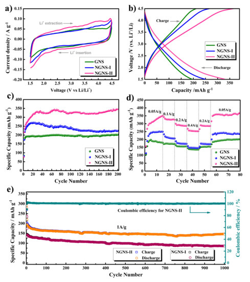
Figure 22.
(a) Cyclic voltammogram of GNS, NGNS-I, and NGNS-II electrodes in the second cycle at a scan rate of 0.1 mV s−1; (b) Galvanostatic charge–discharge profiles, and (c) cycle performance of GNS, NGNS-I, and NGNS-II electrodes at a current density of 0.05 A g−1; (d) Rate performance of GNS, NGNS-I, and NGNS-II electrodes at various current densities in the range of 0.05–0.4 A g−1; and (e) Cycle performance of NGNS-I and NGNS-II electrodes (up to 1000 cycles) and the Coulombic efficiency of NGNS-II at a high current density of 1 A g−1. All experiments were in a voltage range of 1.5–4.5 V vs. Li/Li+. Adapted and reproduced with permission from Ref. [101]. Copyright 2017 American Chemical Society.
4.2.3. Graphene/Metal Chalcogenide Composites as Cathodes for LIBs
Conventional LIBs are confined with graphite and lithium metal oxide as anode and cathode, respectively. The safety issues and reduced cycling stability have paved a way for researchers to explore newer materials as components for lithium-ion batteries. Among chalcogenides, sulfur compounds have a potential role as a cathode that possesses an elevated energy density of 2600 Wh kg−1. The property of sulfide compounds to form polysulfide compounds with lithium has been investigated in lithium-sulfur batteries [102]. The lack of cyclability of such cells has diminished the performance of such batteries [103]. Recently, Chang et al. [103] reported the molybdenum sulfide composited rGO as cathode for lithium-ion batteries. The electrode fabrication is being conducted by electrochemical pulverization of MoS3 from bulk. The presence of an oxygenated functional group on the rGO surface adheres to the nano MoS3 particles on its surface, ensuring the synergistic effect of both components. The electrochemical analysis of half-cell delivered voltage stability in the range of 0.5–3 V vs. Li/Li+ and full cell study with lithiated Si/C anode displayed an initial discharge performance of 2062 mAh g−1 at 0.5 A g−1 that are reduced spontaneously to 431 mAh g−1 on prolonged cycling up to 24 cycles (Figure 23a). Gradually the capacity was raised to 1126 mAh g−1 on cycling above 110 cycles which retained the performance up to 400 cycles. The cycling stability of the cell conducted at 5C displayed lower capacity initially (700 mAh g−1) which increased to 1200 mAh g−1 on cycling above 1000 cycles followed by a diminishing performance to ~900 mAh g−1 above 1500 cycles, which retained the capacity up to 2500 cycles (Figure 23c) [103].
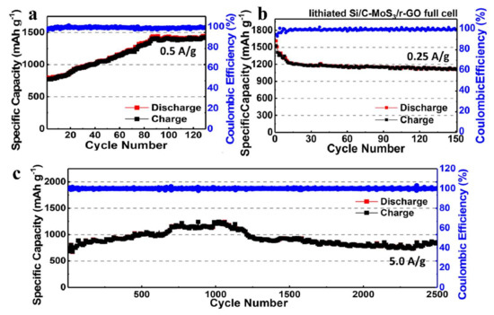
Figure 23.
Cycling performance of a MoS3/r-GO half-cell with electrolyte additive (FEC); (a) the half-cell test for the MoS3/r-GO for the cathode with electrolyte additive (FEC) is carried out between 0.05 and 3.0 V at 25 °C. (b) The cyclability and CE of the full-cell measured at 0.25 A g−1 for 150 cycles. (c) The half-cell test for the MoS3/r-GO for the cathode with FEC is carried out between 0.05 and 3.0 V, respectively, at 25 °C. The cyclability and Coulombic efficiency (CE) of the MoS3/r-GO half-cell is measured at 5.0 A g−1 (5C based on average reversible capacity (∼1000 mAh g−1) over 2500 cycles. The specific capacity is calculated based on the MoS3/r-GO cathode. Adapted and reproduced with permission from Ref. [103]. Copyright 2019 American Chemical Society.
4.2.4. Graphene/Silicate Composites as Cathodes for LIBs
Graphene silicate composites are one of the rarely explored composites as cathode for LIBs. Among graphene silicate composites, the most widely are is Li2FeSiO4 [95,104], Li2MnSiO4 [105], and Li2VSi2O6 [106], etc. Li2FeSiO4 is also abbreviated as LFS and is widely explored among silicate cathodes owing to its theoretical capacity of 332 mAh g−1 which accommodates two lithium ions in the lattice [95]. Even though the LFS possess better theoretical capacity, the performance is less due to the reduced electrical conductivity, hence to enhance the performance of cathode LFS is composited with rGO. Zhang et al. [95] reported rGO modified LFS/C composite cathode synthesized by citrate-nitrate gel combustion (sol-gel) method with citric acid as a chelating agent. A control sample without rGO was also synthesized to compare the electrochemical performance of the material. The electrochemical studies revealed LFS/(C + rGO) electrode displayed an enhanced initial discharge capacity of 188.7 mAh g−1 compared with LFS/C which delivered an initial discharge capacity of 162.1 mAh g−1 at 0.1 C. The electronic conductivity of the LFS/(C + rGO) cathode showed considerable enhancement of 1.5 × 10⁻³ S cm−1 due to incorporation of rGO compared with that of the LFS/C cathode which displayed an electronic conductivity of 7.1 × 10⁻⁴ S cm−1. Similarly, Zhu et al. [105] reported Li2MnSiO4 C/graphene cathode for LIBs. The electrochemical studies revealed that LMS/C/G composite displayed initial charge/discharge capacities of 336.5 and 270.7mAh g−1, respectively, gradually decreasing the discharge capacity to 252.7mAh g−1 in the 5th cycle. The author, Reddy, reported the synthesis and electrochemical performance of Li2VSi2O6/G cathode for LIBs synthesized by single-step solid-state reaction at 900 °C in Ar atmosphere. The half cell test displayed a discharge capacity of 108 mAh g−1 at a current density of 20 mA g−1 (0.15 C)over a potential window of 1.5–4.5 V Li/Li+ at room temperature [106].
4.2.5. Graphene/Phosphate Composites as Cathodes for Lithium-Ion Batteries
Phosphate-based cathodes belong to the most accepted cathode material owing to enhanced safety, cycling stability, and low cost of the material. Among phosphates, lithium iron phosphate is the most widely explored cathode in LIBs. Lithium Ferro phosphate, otherwise known as lithium iron phosphate and abbreviated as LFP, is one of the most widely investigated cathode materials for LIBs. Even though the energy density and voltage stability window of LFP is lower than that of LCO, considering the risk factors associated with LCO makes LFP a prominent alternative cathode material. The energy density of LFP is around 90–160 Wh kg−1 with a nominal cell voltage of 3.2 V, whereas in LCO the energy density ranges from 150 to 200 Wh kg−1 with a nominal cell voltage of 3.6 V. In 2014, Zhu et al. [107] reported LFP/rGO composite cathode with high performance. GO was synthesized by modified Hummer’s method followed by composition by in situ synthesis of LFP from Fe(NO3)3, NH4H2PO4, and urea, followed by refluxing at 90 °C for 1.5 h. The resultant product was then annealed at inert atmosphere for about 8 h to ensure complete conversion to obtain phase pure composite. The rGO/LFP composite with 15 wt.% of rGO delivered an initial charge/discharge capacity of 160.2 and 172 mAh g−1. On prolonged cycling up to 50 cycles, the hybrid cell displayed a specific capacity of 168 mAh g−1 with a capacity retention of 97.5%.
Zhou et al. [108] reported graphene-modified LiFePO4 cathode for LIBs. Contradictory to the previous method, herein LFP and GO were synthesized separately followed by mixing both the systems LFP/GO (10:1 v/v) by ultra-sonication followed by spray drying the composite. The resultant composite of LFP/GO was then annealed at 600 °C for 5 h at Ar atmosphere for converting GO to rGO. A schematic representation of the same has been depicted in Figure 24. The morphological analysis of the composites have been displayed in Figure 25a reveals that the LFP/G forms secondary quasi-spherical particles in the micrometer regime (2–5 μm). On increased magnification (Figure 25b) the aggregation of the LFP nanoparticles entrapped in graphene sheets is displayed. The elemental mapping of LFP nanoparticles (red) and graphene (green) supports the inference of the SEM analysis (Figure 25c,d). Figure 25e and f further confirm the entrapment of LFP in graphene sheets. On comparison of the electrochemical performance of the samples, LFP/G displayed better performance with an initial discharge capacity of 148 mAh g−1 whereas LFP/C/G displayed performance of ~150 mAh g−1 at 0.1C. The studies revealed that the LFP/C/G is a more efficient cathode than LFP/G owing to the incorporation of activated carbon. Kim et al. [109] reported catalyst assistant self-assembly of graphene on LFP. The electrochemical study of the samples was compared with carbon-coated LFP samples revealing that both the cathodes discharge capacities of ∼150 mAh g−1 at 1 C. After 100 cycles, the G/LFP delivered a discharge capacity of 135 mAh g−1 with retention of 95.0% of its initial discharge capacity, C/LFP displayed a discharge capacity of 121 mAh g−1 with a capacity retention of 86.7%.

Figure 24.
Schematic illustration of the synthesis of rGO modified LiFePO4. Adapted and reproduced with permission from Ref. [108]. Copyright 2011 Royal Society of Chemistry.
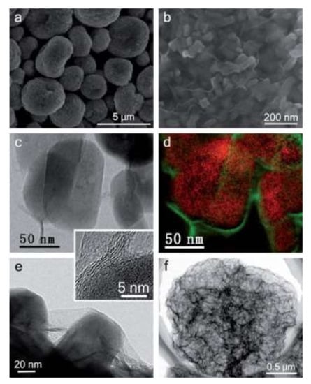
Figure 25.
Illustration of the preparation process and the microscale structure of LFP/graphene composite. (a,b) SEM images show an overview of the LFP/G particles, (c) TEM image of the LFP/G particles, (d) corresponding elemental map using EELS of the same area showing graphene-sheets wrapping on LFP nanoparticles, where red represents the LFP nanoparticles, obtained from the P L-edge, and the green represents graphene sheets, obtained from C K-edge, (e) TEM image on the edge of individual microspheres. The inset is a high-resolution TEM image illustrating the 3–5 monolayer thickness of the graphene sheets on the surface of an individual LFP nanoparticle, and (f) TEM image showing a 3D graphene network obtained by removing LFP nanoparticles with an HCl solution. Adapted and reproduced with permission from Ref. [108]. Copyright 2011 Royal Society of Chemistry.
Yang et al. [110] reported a 3D porous hybrid graphene/LFP cathode. The synthesis of the composite electrode was achieved by template free sol-gel method. GNS was synthesized from graphite oxide followed by mixing with lithium dihydrogen phosphate and iron (III) citrate to form a gel which was combusted at 700 °C for 10 h at Ar atmosphere. A control sample was prepared by omitting the GNS to form porous LFP structures. A schematic illustration of the synthesis of porous graphene LFP composite (p-G/LFP) and porous LFP (p-LFP) has been depicted in Figure 26. The electrochemical analysis of the P-LFP and p-G/LFP showed a considerable difference of ~100 and ~130 mAh g−1 at a current density of 17 mA g−1 [110].

Figure 26.
Schematic representation of the formation of 3D porous networks (a) LFP/graphene and (b) LFP. Adapted and reproduced with permission from Ref. [110]. Copyright 2012 Elsevier.
4.2.6. Graphene Polymer Composites as Cathodes for Lithium-Ion Batteries
Several polymers are explored as a composite material with graphene as cathode for LIBs. Polyimides are the most prominent polymer in this category [111,112]. Unless, like inorganic cathodes, organic cathodes are more flexible and stable, which is capable to enhance the cycle stability of the batteries. The diminished conductivity of organic electrolyte retards its efficiency; hence, to elevate the conductivity of these materials, graphene compounds are incorporated as composites. In 2016, Ahmad et al. [112] reported graphene polyimide cathodes for LIBs. In the proposed synthesis, exfoliated graphene was mixed with pyromellitic dianhydride (PMDA) monomer and ethylenediamine (EDA) (1:1 ratio) in N-methyl pyrrolidone (NMP) solvent followed by refluxation at 150 °C under inert atmosphere for 9 h. The synthesized composite was washed in ethanol followed by drying at an inert atmosphere (300 °C for 7 h). The resultant product was dissolved in acetone and extracted with the Soxhlet apparatus. The electrochemical performance of the material was investigated in a half cell with an electrode fabricated with active material/ conductive carbon and PTFE binder in the ratio 65:30:5. The role of the polymer was analyzed by varying the concentration of the monomer PMDA from 0.01 to 0.15 mmol mL−1. At a lower concentration the electrode delivers the capacity of 177 mAh g−1 at 0.1 C, on increase in concentration to 0.05 mmol mL−1, the capacity declined to 167 mAh g−1. On further increase in the concentration of PDMS to 0.15 mmol mL−1, the discharge capacity further decreased to 90 mAh g−1 [112]. On the other hand, Huang et al. [111] reported a 3D polyimide graphene composite synthesized by the one-pot method by mixing 1,4,5,8-naphthalene tetracarboxylic dianhydride (NTCDA) in GO and 1-methyl-2-pyrrolidinone (NMP) mixture, which is ultrasonicated by adding ethylenediamine followed by solvothermal treatment to obtain 3D GNS/PI composite (Figure 27). Electrochemical study of the composite delivered a discharge capacity of 240 mAh g−1 at 40 mA g−1 compared with that of carbon/PI composite which delivered 153 mAh g−1 at the same current density [111].
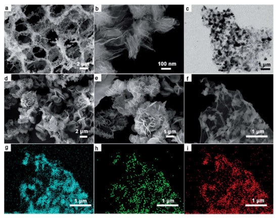
Figure 27.
(a) Low- and (b) high-magnification SEM images and (c) TEM image of GF–PI; (d) low- and (e) high-magnification SEM images of pure PI; (f–i) elemental mapping images of GF–PI (by SEM): carbon (g), N (h), and O (i) distribution in the selected area. Adapted and reproduced with permission from Ref. [111]. Copyright 2017 Royal Society of Chemistry.
4.3. Graphene as Filler in Electrolyte for Lithium-Ion Battery
Electrolytes are an important part of battery technology. Recent research works give more attention to electrolytes, which mainly focuses to satisfy the increasing demand for portable electronic devices and electronic vehicles, with the aim of better energy densities and a long shelf life with a satisfying level of safety at a reasonable price [113]. For the last few decades, the main focus of battery research has been dedicated to electrolytes. Even though liquid electrolytes belong to the primary electrolytes, which have huge benefits such as high ionic conductivity with a good wetting ability which enables wetting of electrode surfaces. The most prominent disadvantages of liquid electrolytes include negligible vapor pressure, low thermal and electrochemical stability, poor ion selectivity, and safety issues [113,114]. The replacement of liquid electrolytes with more stable ionic liquids is one of the alternatives for liquid electrolytes. Ionic liquids are molten salts that exist as a liquid under 100 °C [114]. The first generation LIBs were commercialized by Sony in 1990 with polycarbonate electrolytes [115]. However, the concentration of the electrolyte disrupted the graphitic anodes. The mostly employed lithium salts for electrolytes are LiPF6, LiClO4, LiBF4, LiAsF6, etc. Among these salts, LiPF6 are thermally unstable and LiClO4 is highly explosive when it comes to contact with organics; LiBF4 possess better stability as compared with the above stated, but it interferes at the anode; LiAsF6 is lethal; solutions of LiSO3CF3 possess low conductivities; and LiN(SO2CF3)2 and LiC(SO2CF3)3 corrode of the electrode. LiPF3(C2F5)3 (LiFAP), LiN(SO2CF3)2, (LiTFSI), and LiBC4O8 (LiBOB) are the other salts used in lithium-ion batteries [116]. These drawbacks lead to the development of nonflammable, low-cost electrolytes for LIBs. Polymer electrolytes and solid-state electrolytes are the common categories of electrolytes under study. Solid-state electrolytes for LIBs are mainly categorized into three types, inorganic solid electrolytes, solid polymer electrolytes, and hybrid solid polymer electrolytes. The first class contains solid electrolytes of oxides (garnet, perovskite, anti-perovskite, and LiPON13) and sulfides. The polymer electrolytes are poly(ethylene oxide) (PEO) based systems, polycarbonate-based systems, and polysiloxane-based systems are the main systems [117]. Polymer electrolyte membranes mainly act as a separator in LIBs, and they should need some specifications such as chemical stability, high proton conductivity, low fuel crossover, low electronic conductivity, high permselectivity, low cost, and appropriate thickness with high thermal and mechanical stability [118,119].
Yuan et.al [120] developed a solid polyethylene oxide/lithium salt electrolyte with high surface area and good mechanical strength by adding 1 wt.% GO nanosheet. The tensile strength was enhanced up to 260% compared with that of pristine PEO. The ionic conductivity of the composite polymer electrolyte was 5.6×10⁻⁸ S cm−1 ensuring the application of the same in LIBs. Later, Shim et.al, [121] modified the electrolytic system by incorporating poly(ethylene glycol)-grafted graphene oxide (PGO) as filler in an organic/inorganic hybrid copolymer electrolyte. The organic/inorganic hybrid copolymer electrolyte employed was branched-graft copolymer (BCP) based on poly(ethylene glycol) methyl ether methacrylate (PEGMA) and 3-(3,5,7,9,11,13,15-hepta isobutyl pentacyclo-[9.5.1.13,9.15,15.17,13]octasiloxane-1-yl)propyl methacrylate (MA-POSS) was used as polymer matrix. The addition of 0.2 wt.% PGO showed considerable enhancement in the ionic conductivity of 2.1 × 10⁻⁴ S cm−1 whereas pristine co-polymer delivered an ionic conductivity of 1.1 × 10⁻⁵ S cm−1. The linear sweep voltammetry of the samples revealed a stability window extending up to 5.3 V at 60°C. The cell performance of the cells was analyzed in Li/SPE/V2O5 cells. The composite BCP/PGO electrolyte delivered an initial discharge capacity of 287 mAh g−1 at 0.1 C rate (60°C) which was considerably higher than that of pristine BCP (~185 mAh g−1 at 0.1 C rate).
Recently, sulfide-based electrolytes are widely used due to their unique properties such as high ionic conductivity and wide electrochemical windows. However, in a lithium-ion battery, it might be due to severe issues such as obstructing the lithium-ion flow during the cycling process and increased interfacial resistance. To control these problems, Li et al. [122] produced GO-coated solid electrolyte Li7P3S11 (LPS) through the solution synthesis method. This electrolyte particularly addresses the concerns of interfacial stability between the sulfide solid electrolyte and shows improved performance and excellent cycling stability with the 1% GO/LPS. The other solid electrolyte was reported by Wen et al. [117]. In that report, (GO) is employed to improve the electrochemical performance, thermal stability, and mechanical strength of the poly (ethylene oxide) (PEO) based electrolyte. They represent the electrolyte as LiFePO4//GO-PEO//Li, showing the discharge capacity of 142 mAh g−1 at 0.5 C, and 91% capacity retention after 100 cycles are the highlights. It can also complete a stable cycle charging and discharging process.
5. Conclusions
The present review summarizes the use of graphene and its composites as components in lithium-ion batteries. Exploring the relevant as well as new studies, it has been shown how graphene enhances the rate capability and performances, and how it reduces the shutter effects in lithium-ion batteries. From the information available, one could conclude that without graphene, the energy storage devices could not produce better performances. The structure and the specific characteristics are the highlights of graphene. Optimistically, the day is not far away when the effective application of graphene-based anode in rechargeable batteries will be treated as an innovation in battery performance. For practical applications of bare graphene, further reduction in discharge and charge voltages is needed.
Author Contributions
Conceptualization, M.V.V.R. and P.R.; writing—original draft preparation, R.J., N.T.M.B., A.D. and S.S.; writing—review and editing, V.K.T. and K.Z.; supervision, writing—review and editing, J.F.M.J., M.V.V.R. and P.R. All authors have read and agreed to the published version of the manuscript.
Funding
This research received no external funding.
Institutional Review Board Statement
Not applicable.
Informed Consent Statement
Not applicable.
Acknowledgments
Authors Jabeen Fatima M.J. and Prasanth Raghavan would like to acknowledge the Kerala State Council for Science, Technology, and Environment (KSCSTE) and Kerala State Higher Education Council, Government of Kerala for financial assistance.
Conflicts of Interest
The authors declare no conflict of interest. The funders had no role in the design of the study; in the collection, analyses, or interpretation of data; in the writing of the manuscript, or in the decision to publish the results.
References
- Zhang, H.; Chen, N.; Sun, C.; Luo, X. Investigations on physicochemical properties and electrochemical performance of graphite felt and carbon felt for iron-chromium redox flow battery. Int. J. Energy Res. 2020, 44, 3839–3853. [Google Scholar] [CrossRef]
- Chen, N.; Zhang, H.; Luo, X.-D.; Sun, C.-Y. SiO2-decorated graphite felt electrode by silicic acid etching for iron-chromium redox flow battery. Electrochim. Acta 2020, 336, 135646. [Google Scholar] [CrossRef]
- Akridge, J.; Vourlis, H. Solid state batteries using vitreous solid electrolytes. Solid State Ion. 1986, 18–19, 1082–1087. [Google Scholar] [CrossRef]
- Akridge, J.; Vourlis, H. Performance of Li/TiS2 solid state batteries using phosphorous chalcogenide network former glasses as solid electrolyte. Solid State Ion. 1988, 28–30, 841–846. [Google Scholar] [CrossRef]
- Anderman, M.; Lundquist, J.; Johnson, S.; Giovannoni, R. Rechargeable lithium-titanium disulphide cells of spirally-wound design. J. Power Sources 1989, 26, 309–312. [Google Scholar] [CrossRef]
- Guerard, D.; Herold, A. Intercalation of lithium into graphite and other carbons. Carbon 1975, 13, 337–345. [Google Scholar] [CrossRef]
- Eichinger, G.; Besenhard, J. High energy density lithium cells: Part II. Cathodes and complete cells. J. Electroanal. Chem. Interfacial Electrochem. 1976, 72, 1–31. [Google Scholar] [CrossRef]
- Besenhard, J.; Eichinger, G. High energy density lithium cells: Part I. Electrolytes and anodes. J. Electroanal. Chem. Interfacial Electrochem. 1976, 68, 1–18. [Google Scholar] [CrossRef]
- Reddy, M.V.; Mauger, A.; Julien, C.M.; Paolella, A.; Zaghib, K. Brief History of Early Lithium-Battery Development. Materials 2020, 13, 1884. [Google Scholar] [CrossRef] [Green Version]
- Yu, P.; Lowe, S.E.; Simon, G.; Zhong, Y.L. Electrochemical exfoliation of graphite and production of functional graphene. Curr. Opin. Colloid Interface Sci. 2015, 20, 329–338. [Google Scholar] [CrossRef]
- Media, N. (2014) Nobel Prize in Physics. In: Nobelprize.org. Nobel Media AB. Available online: https://www.nobelprize.org/prizes/physics/2010/geim/facts/%0Ahttps://www.nobelprize.org/nobel_prizes/physics/laureates/2010/geim-facts.html (accessed on 24 December 2021).
- Geng, C.-Y.; Yu, J.; Shi, F.-N. Few-layers of graphene modified TiO2/graphene composites with excellent electrochemical properties for lithium-ion battery. Ionics 2019, 25, 3059–3068. [Google Scholar] [CrossRef]
- Ouyang, D.-D.; Hu, L.-B.; Wang, G.; Dai, B.; Yu, F.; Zhang, L.-L. A review of biomass-derived graphene and graphene-like carbons for electrochemical energy storage and conversion. New Carbon Mater. 2021, 36, 350–372. [Google Scholar] [CrossRef]
- Tiwari, S.K.; Sahoo, S.; Wang, N.; Huczko, A. Graphene research and their outputs: Status and prospect. J. Sci. Adv. Mater. Devices 2020, 5, 10–29. [Google Scholar] [CrossRef]
- Kumar, R.K.; Bandurin, D.A.; Pellegrino, F.M.D.; Cao, Y.; Principi, A.; Guo, H.; Auton, G.H.; Ben Shalom, M.; Ponomarenko, L.A.; Falkovich, G.; et al. Superballistic flow of viscous electron fluid through graphene constrictions. Nat. Phys. 2017, 13, 1182–1185. [Google Scholar] [CrossRef] [Green Version]
- Peter, F.S.; Raghavan, P.; Figerez, S.P.; Prasanth, R. Graphene and Carbon Nanotubes for Advanced Lithium Ion Batteries, 1st ed.; CRC Press: Boca Raton, FL, USA, 2018. [Google Scholar] [CrossRef]
- Cao, Y.-C.; Xu, C.; Wu, X.; Wang, X.; Xing, L.; Scott, K. A poly (ethylene oxide)/graphene oxide electrolyte membrane for low temperature polymer fuel cells. J. Power Sources 2011, 196, 8377–8382. [Google Scholar] [CrossRef]
- Alshamsi, H.A.; Jaber, N.A.A.-B.; Altaa, S.H.A. Facile Green Synthesis of Reduced Graphene Oxide in L-cysteine Solution and its Structural, Morphological, Optical and Thermal Characteristics. J. Physics: Conf. Ser. 2021, 1999, 012016. [Google Scholar] [CrossRef]
- Madurani, K.A.; Suprapto, S.; Machrita, N.I.; Bahar, S.L.; Illiya, W.; Kurniawan, F. Progress in Graphene Synthesis and its Application: History, Challenge and the Future Outlook for Research and Industry. ECS J. Solid State Sci. Technol. 2020, 9, 093013. [Google Scholar] [CrossRef]
- Wu, Z.-S.; Zhou, G.; Yin, L.-C.; Ren, W.; Li, F.; Cheng, H.-M. Graphene/metal oxide composite electrode materials for energy storage. Nano Energy 2012, 1, 107–131. [Google Scholar] [CrossRef]
- Geim, A.K.; Novoselov, K.S. The rise of graphene. Nat. Mater. 2007, 6, 183–191. [Google Scholar] [CrossRef]
- Krishnamoorthy, K.; Kim, G.-S.; Kim, S.J. Graphene nanosheets: Ultrasound assisted synthesis and characterization. Ultrason. Sonochemistry 2013, 20, 644–649. [Google Scholar] [CrossRef]
- Khan, M.; Tahir, M.N.; Adil, S.F.; Khan, H.U.; Siddiqui, M.R.H.; Al-Warthan, A.A.; Tremel, W. Graphene based metal and metal oxide nanocomposites: Synthesis, properties and their applications. J. Mater. Chem. A 2015, 3, 18753–18808. [Google Scholar] [CrossRef] [Green Version]
- Edwards, R.S.; Coleman, K.S. Graphene synthesis: Relationship to applications. Nanoscale 2012, 5, 38–51. [Google Scholar] [CrossRef] [PubMed]
- Choi, W.; Lahiri, I.; Seelaboyina, R.; Kang, Y.S. Synthesis of Graphene and Its Applications: A Review. Crit. Rev. Solid State Mater. Sci. 2010, 35, 52–71. [Google Scholar] [CrossRef]
- Botas, C.; Álvarez, P.; Blanco, P.; Granda, M.; Blanco, C.; Santamaria, R.; Romasanta, L.J.; Verdejo, R.; López-Manchado, M.A.; Menéndez, R. Graphene materials with different structures prepared from the same graphite by the Hummers and Brodie methods. Carbon 2013, 65, 156–164. [Google Scholar] [CrossRef] [Green Version]
- Sehrawat, P.; Shabir, A.; Abid; Julien, C.; Islam, S. Recent trends in silicon/graphene nanocomposite anodes for lithium-ion batteries. J. Power Sources 2021, 501, 229709. [Google Scholar] [CrossRef]
- Liang, M.; Zhi, L. Graphene-based electrode materials for rechargeable lithium batteries. J. Mater. Chem. 2009, 19, 5871–5878. [Google Scholar] [CrossRef]
- Geng, C.-Y.; Yu, J.; Shi, F.-N. Electrochemical study on different layers of graphene based TiO2/graphene composites as an anode for lithium-ion batteries. Res. Chem. Intermed. 2019, 45, 3409–3424. [Google Scholar] [CrossRef]
- Guo, B.; Ananth, K.P.; Zhang, J.; Ji, X.; Bai, J. Investigation of wet-milled graphene nanosheets with sulfur doping for lithium-ion battery. Ionics 2020, 26, 3267–3274. [Google Scholar] [CrossRef]
- Sui, D.; Si, L.; Li, C.; Yang, Y.; Zhang, Y.; Yan, W. A Comprehensive Review of Graphene-Based Anode Materials for Lithium-ion Capacitors. Chemistry 2021, 3, 1215–1246. [Google Scholar] [CrossRef]
- Yoo, E.; Kim, J.; Hosono, E.; Zhou, H.-S.; Kudo, T.; Honma, I. Large Reversible Li Storage of Graphene Nanosheet Families for Use in Rechargeable Lithium Ion Batteries. Nano Lett. 2008, 8, 2277–2282. [Google Scholar] [CrossRef]
- Guo, P.; Song, H.; Chen, X. Electrochemical performance of graphene nanosheets as anode material for lithium-ion batteries. Electrochem. Commun. 2009, 11, 1320–1324. [Google Scholar] [CrossRef]
- Vargas, O.; Caballero, A.; Morales, J.; Elia, G.A.; Scrosati, B.; Hassoun, J. Electrochemical performance of a graphene nanosheets anode in a high voltage lithium-ion cell. Phys. Chem. Chem. Phys. 2013, 15, 20444–20446. [Google Scholar] [CrossRef]
- Li, X.; Hu, Y.; Liu, J.; Lushington, A.; Li, R.; Sun, X. Structurally tailored graphene nanosheets as lithium ion battery anodes: An insight to yield exceptionally high lithium storage performance. Nanoscale 2013, 5, 12607–12615. [Google Scholar] [CrossRef] [PubMed]
- Mu, Y.; Han, M.; Li, J.; Liang, J.; Yu, J. Growing vertical graphene sheets on natural graphite for fast charging lithium-ion batteries. Carbon 2020, 173, 477–484. [Google Scholar] [CrossRef]
- Wu, D.H.; Li, Y.F.; Zhou, Z. First-principles studies on doped graphene as anode materials in lithium-ion batteries. Theor. Chim. Acc. 2011, 130, 209–213. [Google Scholar] [CrossRef]
- Panchakarla, L.S.; Subrahmanyam, K.S.; Saha, S.K.; Govindaraj, A.; Krishnamurthy, H.R.; Waghmare, U.V.; Rao, C.N.R. Synthesis, Structure, and Properties of Boron- and Nitrogen-Doped Graphene. Adv. Mater. 2009, 21, 4726–4730. [Google Scholar] [CrossRef]
- Li, X.; Geng, D.; Zhang, Y.; Meng, X.; Li, R.; Sun, X. Superior cycle stability of nitrogen-doped graphene nanosheets as anodes for lithium ion batteries. Electrochem. Commun. 2011, 13, 822–825. [Google Scholar] [CrossRef]
- Tan, Y.; Zhu, K.; Li, D.; Bai, F.; Wei, Y.; Zhang, P. N-doped graphene/Fe–Fe3C nano-composite synthesized by a Fe-based metal organic framework and its anode performance in lithium ion batteries. Chem. Eng. J. 2014, 258, 93–100. [Google Scholar] [CrossRef]
- Dong, X.; Zheng, X.; Deng, Y.; Wang, L.; Hong, H.; Ju, Z. SiO2/N-doped graphene aerogel composite anode for lithium-ion batteries. J. Mater. Sci. 2020, 55, 13023–13035. [Google Scholar] [CrossRef]
- Ni, S.; Zhang, J.; Ma, J.; Yang, X.; Zhang, L. Li3VO4/N-doped graphene with high capacity and excellent cycle stability as anode for lithium ion batteries. J. Power Sources 2015, 296, 377–382. [Google Scholar] [CrossRef]
- Xiao, Z.; Sheng, L.; Jiang, L.; Zhao, Y.; Jiang, M.; Zhang, X.; Zhang, M.; Shi, J.; Lin, Y.; Fan, Z. Nitrogen-doped graphene ribbons/MoS2 with ultrafast electron and ion transport for high-rate Li-ion batteries. Chem. Eng. J. 2020, 408, 127269. [Google Scholar] [CrossRef]
- Pant, H.; Petnikota, S.; Vadali, V.S.S.S. Review—Brief Review of the Solid-State Graphenothermal Reduction for Processing Metal Oxide-Reduced Graphene Oxide Nanocomposites for Energy Applications. ECS J. Solid State Sci. Technol. 2021, 10, 031002. [Google Scholar] [CrossRef]
- Wu, Z.-S.; Ren, W.; Wen, L.; Gao, L.; Zhao, J.; Chen, Z.; Zhou, G.; Li, F.; Cheng, H.-M. Graphene Anchored with Co3O4 Nanoparticles as Anode of Lithium Ion Batteries with Enhanced Reversible Capacity and Cyclic Performance. ACS Nano 2010, 4, 3187–3194. [Google Scholar] [CrossRef] [PubMed]
- Zhao, X.; Hayner, C.M.; Kung, M.C.; Kung, H.H. In-Plane Vacancy-Enabled High-Power Si-Graphene Composite Electrode for Lithium-Ion Batteries. Adv. Energy Mater. 2011, 1, 1079–1084. [Google Scholar] [CrossRef]
- Lee, J.K.; Smith, K.B.; Hayner, C.M.; Kung, H.H. Silicon nanoparticles–graphene paper composites for Li ion battery anodes. Chem. Commun. 2010, 46, 2025–2027. [Google Scholar] [CrossRef] [PubMed]
- Zhou, G.; Wang, D.-W.; Li, F.; Zhang, L.; Li, N.; Wu, Z.-S.; Wen, L.; Lu, G.Q.; Cheng, H.-M. Graphene-Wrapped Fe3O4 Anode Material with Improved Reversible Capacity and Cyclic Stability for Lithium Ion Batteries. Chem. Mater. 2010, 22, 5306–5313. [Google Scholar] [CrossRef]
- Zhang, L.-S.; Jiang, L.-Y.; Yan, H.-J.; Wang, W.D.; Song, W.-G.; Guo, Y.-G.; Wan, L.-J. Mono dispersed SnO2 nanoparticles on both sides of single layer graphene sheets as anode materials in Li-ion batteries. J. Mater. Chem. 2010, 20, 5462–5467. [Google Scholar] [CrossRef]
- Mai, Y.; Wang, X.; Xiang, J.; Qiao, Y.; Zhang, D.; Gu, C.; Tu, J. CuO/graphene composite as anode materials for lithium-ion batteries. Electrochim. Acta 2011, 56, 2306–2311. [Google Scholar] [CrossRef]
- Choi, D.; Wang, D.; Viswanathan, V.V.; Bae, I.-T.; Wang, W.; Nie, Z.; Zhang, J.-G.; Graff, G.L.; Liu, J.; Yang, Z.; et al. Li-ion batteries from LiFePO4 cathode and anatase/graphene composite anode for stationary energy storage. Electrochem. Commun. 2010, 12, 378–381. [Google Scholar] [CrossRef]
- Chang, K.; Chen, W. L-Cysteine-Assisted Synthesis of Layered MoS2/Graphene Composites with Excellent Electrochemical Performances for Lithium Ion Batteries. ACS Nano 2011, 5, 4720–4728. [Google Scholar] [CrossRef]
- Petnikota, S.; Teo, K.W.; Chen, L.; Sim, A.; Marka, S.K.; Reddy, M.V.; Srikanth, V.V.S.S.; Adams, S.; Chowdari, B. Exfoliated Graphene Oxide/MoO2 Composites as Anode Materials in Lithium-Ion Batteries: An Insight into Intercalation of Li and Conversion Mechanism of MoO2. ACS Appl. Mater. Interfaces 2016, 8, 10884–10896. [Google Scholar] [CrossRef] [PubMed]
- Petnikota, S.; Rotte, N.K.; Reddy, M.V.; Srikanth, V.V.S.S.; Chowdari, B.V.R. MgO-Decorated Few-Layered Graphene as an Anode for Li-Ion Batteries. ACS Appl. Mater. Interfaces 2015, 7, 2301–2309. [Google Scholar] [CrossRef] [PubMed]
- Maseed, H.; Petnikota, S.; Srikanth, V.V.S.S.; Srinivasan, M.; Chowdari, B.V.R.; Reddy, M.V.; Adams, S. Fe2Mo3O8/exfoliated graphene oxide: Solid-state synthesis, characterization and anodic application in Li-ion batteries. New J. Chem. 2018, 42, 12817–12823. [Google Scholar] [CrossRef]
- Marka, S.K.; Petnikota, S.; Srikanth, V.V.S.S.; Reddy, M.V.; Adams, S.; Chowdari, B.V.R. Co2Mo3O8/reduced graphene oxide composite: Synthesis, characterization, and its role as a prospective anode material in lithium ion batteries. RSC Adv. 2016, 6, 55167–55175. [Google Scholar] [CrossRef]
- Hameed, A.S.; Reddy, M.V.; Chen, J.L.T.; Chowdari, B.V.R.; Vittal, J.J. RGO/Stibnite Nanocomposite as a Dual Anode for Lithium and Sodium Ion Batteries. ACS Sustain. Chem. Eng. 2016, 4, 2479–2486. [Google Scholar] [CrossRef]
- Zhu, X.; Zhu, Y.; Murali, S.; Stoller, M.D.; Ruoff, R.S. Nanostructured Reduced Graphene Oxide/Fe2O3 Composite as a High-Performance Anode Material for Lithium Ion Batteries. ACS Nano 2011, 5, 3333–3338. [Google Scholar] [CrossRef]
- Petnikota, S.; Marka, S.K.; Banerjee, A.; Reddy, M.; Srikanth, V.; Chowdari, B. Graphenothermal reduction synthesis of ‘exfoliated graphene oxide/iron (II) oxide’ composite for anode application in lithium ion batteries. J. Power Sources 2015, 293, 253–263. [Google Scholar] [CrossRef]
- Petnikota, S.; Marka, S.K.; Srikanth, V.V.; Reddy, M.V.; Chowdari, B.V. Elucidation of few layered graphene-complex metal oxide (A2Mo3O8, A = Co, Mn and Zn) composites as robust anode materials in Li ion batteries. Electrochim. Acta 2015, 178, 699–708. [Google Scholar] [CrossRef]
- Goh, B.-M.; Wang, Y.; Reddy, M.V.; Ding, Y.L.; Lu, L.; Bunker, C.; Loh, K.P. Filling the Voids of Graphene Foam with Graphene “Eggshell” for Improved Lithium-Ion Storage. ACS Appl. Mater. Interfaces 2014, 6, 9835–9841. [Google Scholar] [CrossRef] [PubMed]
- Han, F.; Li, D.; Li, W.-C.; Lei, C.; Sun, Q.; Lu, A.-H. Nanoengineered Polypyrrole-Coated Fe2O3@C Multifunctional Composites with an Improved Cycle Stability as Lithium-Ion Anodes. Adv. Funct. Mater. 2012, 23, 1692–1700. [Google Scholar] [CrossRef]
- Yan, Y.; Tang, H.; Wu, F.; Xie, Z.; Xu, S.; Qu, D.; Wang, R.; Wu, F.; Pan, M.; Qu, D. Facile synthesis of Fe2O3@graphite nanoparticle composite as the anode for Lithium ion batteries with high cyclic stability. Electrochim. Acta 2017, 253, 104–113. [Google Scholar] [CrossRef]
- Sun, M.; Sun, M.; Yang, H.; Song, W.; Nie, Y.; Sun, S. Porous Fe2O3 nanotubes as advanced anode for high performance lithium ion batteries. Ceram. Int. 2016, 43, 363–367. [Google Scholar] [CrossRef]
- Lv, X.; Deng, J.; Wang, B.; Zhong, J.; Sham, T.-K.; Sun, X.; Sun, X. γ-Fe2O3@CNTs Anode Materials for Lithium Ion Batteries Investigated by Electron Energy Loss Spectroscopy. Chem. Mater. 2017, 29, 3499–3506. [Google Scholar] [CrossRef]
- Peng, P.; Zhao, Q.; Zhu, P.; Liu, W.; Yuan, Y.; Ding, R.; Gao, P.; Sun, X.; Liu, E. Amorphous Fe2O3 film-coated mesoporous Fe2O3 core-shell nanosphere prepared by quenching as a high-performance anode material for lithium-ion batteries. J. Electroanal. Chem. 2021, 898, 115633. [Google Scholar] [CrossRef]
- Wang, G.; Liu, T.; Luo, Y.; Zhao, Y.; Ren, Z.; Bai, J.; Wang, H. Preparation of Fe2O3/graphene composite and its electrochemical performance as an anode material for lithium ion batteries. J. Alloys. Compd. 2011, 509, L216–L220. [Google Scholar] [CrossRef]
- Li, H.; Zhu, X.; Sitinamaluwa, H.; Wasalathilake, K.; Xu, L.; Zhang, S.; Yan, C. Graphene oxide wrapped Fe2O3 as a durable anode material for high-performance lithium-ion batteries. J. Alloys Compd. 2017, 714, 425–432. [Google Scholar] [CrossRef] [Green Version]
- Wang, P.; Gou, X.-X.; Xin, S.; Cao, F.-F. Facile synthesis of CuO nanochains as high-rate anode materials for lithium-ion batteries. New J. Chem. 2019, 43, 6535–6539. [Google Scholar] [CrossRef]
- Liu, Y.; Qiao, Y.; Zhang, W.; Hu, P.; Chen, C.; Li, Z.; Yuan, L.; Hu, X.; Huang, Y. Facile fabrication of CuO nanosheets on Cu substrate as anode materials for electrochemical energy storage. J. Alloys Compd. 2014, 586, 208–215. [Google Scholar] [CrossRef]
- Jia, S.; Wang, Y.; Liu, X.; Zhao, S.; Zhao, W.; Huang, Y.; Li, Z.; Lin, Z. Hierarchically porous CuO nano-labyrinths as binder-free anodes for long-life and high-rate lithium ion batteries. Nano Energy 2019, 59, 229–236. [Google Scholar] [CrossRef]
- Su, Q.; Yao, L.; Zhang, J.; Du, G.; Xu, B. In Situ Transmission Electron Microscopy Observation of the Lithiation-Delithiation Conversion Behavior of CuO/Graphene Anode. ACS Appl. Mater. Interfaces. 2015, 7, 23062–23068. [Google Scholar] [CrossRef]
- Liu, Y.; Wang, W.; Gu, L.; Wang, Y.; Ying, Y.; Mao, Y.; Sun, L.; Peng, X. Flexible CuO Nanosheets/Reduced-Graphene Oxide Composite Paper: Binder-Free Anode for High-Performance Lithium-Ion Batteries. ACS Appl. Mater. Interfaces 2013, 5, 9850–9855. [Google Scholar] [CrossRef]
- Choi, S.H.; Kang, Y.C. Crumpled Graphene-Molybdenum Oxide Composite Powders: Preparation and Application in Lithium-Ion Batteries. ChemSusChem 2013, 7, 523–528. [Google Scholar] [CrossRef] [PubMed]
- Almodóvar, P.; López, M.L.; Ramírez-Castellanos, J.; Nappini, S.; Magnano, E.; González-Calbet, J.M.; Díaz-Guerra, C. Synthesis, characterization and electrochemical assessment of hexagonal molybdenum trioxide (h-MoO3) micro-composites with graphite, graphene and graphene oxide for lithium ion batteries. Electrochim. Acta 2020, 365, 137355. [Google Scholar] [CrossRef]
- Vazquez-Santos, M.B.; Tartaj, P.; Morales, E.; Amarilla, J.M. TiO2 Nanostructures as Anode Materials for Li/Na-Ion Batteries. Chem. Rec. 2018, 18, 1178–1191. [Google Scholar] [CrossRef]
- Xin, X.; Zhou, X.; Wu, J.; Yao, X.; Liu, Z. Scalable Synthesis of TiO2/Graphene Nanostructured Composite with High-Rate Performance for Lithium Ion Batteries. ACS Nano 2012, 6, 11035–11043. [Google Scholar] [CrossRef] [PubMed]
- Zhang, C.; Liu, S.; Qi, Y.; Cui, F.; Yang, X. Conformal carbon coated TiO2 aerogel as superior anode for lithium-ion batteries. Chem. Eng. J. 2018, 351, 825–831. [Google Scholar] [CrossRef]
- Choi, S.I.; Jung, E.-J.; Park, M.; Shin, H.-S.; Huh, S.; Won, Y.S. Phase-dependent performance of lotus-root shaped TiO2 anode for lithium-ion batteries (LIBs). Appl. Surf. Sci. 2020, 508, 145237. [Google Scholar] [CrossRef]
- Zhang, Y.; Tang, Y.; Li, W.; Chen, X. Nanostructured TiO2-Based Anode Materials for High-Performance Rechargeable Lithium-Ion Batteries. ChemNanoMat 2016, 2, 764–775. [Google Scholar] [CrossRef]
- Qiu, J.; Zhang, P.; Ling, M.; Li, S.; Liu, P.; Zhao, H.; Zhang, S. Photocatalytic Synthesis of TiO2 and Reduced Graphene Oxide Nanocomposite for Lithium Ion Battery. ACS Appl. Mater. Interfaces 2012, 4, 3636–3642. [Google Scholar] [CrossRef]
- Li, W.; Wang, F.; Feng, S.; Wang, J.; Sun, Z.; Li, B.; Li, Y.; Yang, J.; Elzatahry, A.; Xia, Y.; et al. Sol–Gel Design Strategy for Ultradispersed TiO2 Nanoparticles on Graphene for High-Performance Lithium Ion Batteries. J. Am. Chem. Soc. 2013, 135, 18300–18303. [Google Scholar] [CrossRef]
- Qiu, J.; Lai, C.; Wang, Y.; Li, S.; Zhang, S. Resilient mesoporous TiO2/graphene nanocomposite for high rate performance lithium-ion batteries. Chem. Eng. J. 2014, 256, 247–254. [Google Scholar] [CrossRef]
- Lan, T.; Qiu, H.; Xie, F.; Yang, J.; Wei, M. Rutile TiO2 Mesocrystals/Reduced Graphene Oxide with High-Rate and Long-Term Performance for Lithium-Ion Batteries. Sci. Rep. 2015, 5, 8498. [Google Scholar] [CrossRef] [Green Version]
- Chan, C.K.; Peng, H.; Liu, G.; McIlwrath, K.; Zhang, X.F.; Huggins, R.A.; Cui, Y. High-performance lithium battery anodes using silicon nanowires. Nat. Nanotechnol. 2007, 3, 31–35. [Google Scholar] [CrossRef] [PubMed]
- Kim, N.; Oh, C.; Kim, J.; Kim, J.-S.; Jeong, E.D.; Bae, J.-S.; Hong, T.E.; Lee, J.K. High-Performance Li-Ion Battery Anodes Based on Silicon-Graphene Self-Assemblies. J. Electrochem. Soc. 2016, 164, A6075–A6083. [Google Scholar] [CrossRef] [Green Version]
- Beattie, S.D.; Larcher, D.; Morcrette, M.; Simon, B.; Tarascon, J.-M. Si Electrodes for Li-Ion Batteries—A New Way to Look at an Old Problem. J. Electrochem. Soc. 2008, 155, A158–A163. [Google Scholar] [CrossRef]
- Chou, S.-L.; Wang, J.-Z.; Choucair, M.; Liu, H.-K.; Stride, J.A.; Dou, S.-X. Enhanced reversible lithium storage in a nanosize silicon/graphene composite. Electrochem. Commun. 2010, 12, 303–306. [Google Scholar] [CrossRef]
- Yi, X.; Zhang, Y.; He, W.; Zhang, X.; Yang, G.; Wang, Z.; Wang, Y.; Cheng, Q. Low-Temperature Synthesis of Graphene/SiC Nanocomposite Anodes with Super-Long Cycling Stability. ChemElectroChem 2017, 4, 1320–1326. [Google Scholar] [CrossRef]
- Shi, L.; Pang, C.; Chen, S.; Wang, M.; Wang, K.; Tan, Z.; Gao, P.; Ren, J.; Huang, Y.; Peng, H.; et al. Vertical Graphene Growth on SiO Microparticles for Stable Lithium Ion Battery Anodes. Nano Lett. 2017, 17, 3681–3687. [Google Scholar] [CrossRef]
- Li, H.; Lu, C.; Zhang, B. A straightforward approach towards Si@C/graphene nanocomposite and its superior lithium storage performance. Electrochim. Acta 2014, 120, 96–101. [Google Scholar] [CrossRef]
- Ma, X.; Hou, G.; Ai, Q.; Zhang, L.; Si, P.; Feng, J.; Ci, L. A heart-coronary arteries structure of carbon nanofibers/graphene/silicon composite anode for high performance lithium ion batteries. Sci. Rep. 2017, 7, 9642. [Google Scholar] [CrossRef]
- Al Hassan, M.; Sen, A.; Zaman, T.; Mostari, M. Emergence of graphene as a promising anode material for rechargeable batteries: A review. Mater. Today Chem. 2018, 11, 225–243. [Google Scholar] [CrossRef]
- Chen, X.; Tian, Y. Review of Graphene in Cathode Materials for Lithium-Ion Batteries. Energy Fuels 2021, 35, 3572–3580. [Google Scholar] [CrossRef]
- Zhang, L.-L.; Duan, S.; Yang, X.-L.; Peng, G.; Liang, G.; Huang, Y.-H.; Jiang, Y.; Ni, S.-B.; Li, M. Reduced Graphene Oxide Modified Li2FeSiO4/C Composite with Enhanced Electrochemical Performance as Cathode Material for Lithium Ion Batteries. ACS Appl. Mater. Interfaces 2013, 5, 12304–12309. [Google Scholar] [CrossRef] [PubMed]
- Lee, S.W.; Yabuuchi, N.; Gallant, B.M.; Chen, S.; Kim, B.-S.; Hammond, P.T.; Shao-Horn, Y. High-power lithium batteries from functionalized carbon-nanotube electrodes. Nat. Nanotechnol. 2010, 5, 531–537. [Google Scholar] [CrossRef] [PubMed]
- Chen, H.; Armand, M.; Demailly, G.; Dolhem, F.; Poizot, P.; Tarascon, J.-M. From Biomass to a Renewable LiXC6O6 Organic Electrode for Sustainable Li-Ion Batteries. ChemSusChem 2008, 1, 348–355. [Google Scholar] [CrossRef]
- Maseed, H.; Petnikota, S.; Srikanth, V.V.; Rotte, N.K.; Srinivasan, M.; Bonaccorso, F.; Pellegrini, V.; Reddy, M.V. A new insight into Li-staging, in-situ electrochemical exfoliation, and superior Li storage characteristics of highly crystalline few-layered graphene. J. Energy Storage 2021, 41, 102908. [Google Scholar] [CrossRef]
- Ha, S.H.; Jeong, Y.S.; Lee, Y.J. Free Standing Reduced Graphene Oxide Film Cathodes for Lithium Ion Batteries. ACS Appl. Mater. Interfaces 2013, 5, 12295–12303. [Google Scholar] [CrossRef]
- Xiong, D.; Li, X.; Shan, H.; Zhao, Y.; Dong, L.; Xu, H.; Zhang, X.; Li, D.; Sun, X. Oxygen-containing Functional Groups Enhancing Electrochemical Performance of Porous Reduced Graphene Oxide Cathode in Lithium Ion Batteries. Electrochim. Acta 2015, 174, 762–769. [Google Scholar] [CrossRef]
- Xiong, D.; Li, X.; Bai, Z.; Shan, H.; Fan, L.; Wu, C.; Li, D.; Lu, S. Superior Cathode Performance of Nitrogen-Doped Graphene Frameworks for Lithium Ion Batteries. ACS Appl. Mater. Interfaces 2017, 9, 10643–10651. [Google Scholar] [CrossRef]
- Zhao, Y.; Zhang, Y.; Gosselink, D.; Doan, T.N.L.; Sadhu, M.; Cheang, H.-J.; Chen, P. Polymer Electrolytes for Lithium/Sulfur Batteries. Membranes 2012, 2, 553–564. [Google Scholar] [CrossRef] [Green Version]
- Chang, U.; Lee, J.T.; Yun, J.-M.; Lee, B.; Lee, S.W.; Joh, H.-I.; Eom, K.; Fuller, T.F.; Lee, B. In Situ Self-Formed Nanosheet MoS3/Reduced Graphene Oxide Material Showing Superior Performance as a Lithium-Ion Battery Cathode. ACS Nano 2019, 13, 1490–1498. [Google Scholar] [CrossRef]
- Wang, K.; Ren, W.; Yang, J.; Tan, R.; Liu, Y.; Pan, F. Depolarization effects of Li2FeSiO4 nanocrystals wrapped in different conductive carbon networks as cathodes for high performance lithium-ion batteries. RSC Adv. 2016, 6, 47723–47729. [Google Scholar] [CrossRef]
- Zhu, H.; He, H.; Xin, X.; Ma, X.; Zan, L.; Zhang, Y. Facile synthesis of Li2MnSiO4/C/graphene composite with superior high-rate performances as cathode materials for Li-ion batteries. Electrochim. Acta 2015, 155, 116–124. [Google Scholar] [CrossRef]
- Hameed, A.S.; Reddy, M.V.; AlQaradawi, S.; Adams, S. Synthesis, structural and lithium storage studies of graphene-LiVSi2O6 composites. Ionics 2018, 25, 1559–1566. [Google Scholar] [CrossRef]
- Zhu, X.; Hu, J.; Wu, W.; Zeng, W.; Dai, H.; Du, Y.; Liu, Z.; Li, L.; Ji, H.; Zhu, Y. LiFePO4/reduced graphene oxide hybrid cathode for lithium ion battery with outstanding rate performance. J. Mater. Chem. A 2014, 2, 7812–7818. [Google Scholar] [CrossRef]
- Zhou, X.; Wang, F.; Zhu, Y.; Liu, Z. Graphene modified LiFePO4 cathode materials for high power lithium ion batteries. J. Mater. Chem. 2011, 21, 3353–3358. [Google Scholar] [CrossRef]
- Kim, W.; Ryu, W.-H.; Han, D.; Lim, S.; Eom, J.; Kwon, H. Fabrication of Graphene Embedded LiFePO4 Using a Catalyst Assisted Self Assembly Method as a Cathode Material for High Power Lithium-Ion Batteries. ACS Appl. Mater. Interfaces 2014, 6, 4731–4736. [Google Scholar] [CrossRef] [PubMed]
- Yang, J.; Wang, J.; Wang, D.; Li, X.; Geng, D.; Liang, G.; Gauthier, M.; Li, R.; Sun, X. 3D porous LiFePO4/graphene hybrid cathodes with enhanced performance for Li-ion batteries. J. Power Sources 2012, 208, 340–344. [Google Scholar] [CrossRef]
- Huang, Y.; Li, K.; Liu, J.; Zhong, X.; Duan, X.; Shakir, I.; Xu, Y. Three-dimensional graphene/polyimide composite-derived flexible high-performance organic cathode for rechargeable lithium and sodium batteries. J. Mater. Chem. A 2017, 5, 2710–2716. [Google Scholar] [CrossRef]
- Ahmad, A.; Wu, H.; Guo, Y.; Meng, Q.; Meng, Y.; Lu, K.; Liu, L.; Wei, Z. A graphene supported polyimide nanocomposite as a high performance organic cathode material for lithium ion batteries. RSC Adv. 2016, 6, 33287–33294. [Google Scholar] [CrossRef]
- Manthiram, A.; Yu, X.; Wang, S. Lithium battery chemistries enabled by solid-state electrolytes. Nat. Rev. Mater. 2017, 2, 16103. [Google Scholar] [CrossRef]
- Osada, I.; De Vries, H.; Scrosati, B.; Passerini, S. Ionic-Liquid-Based Polymer Electrolytes for Battery Applications. Angew. Chem. Int. Ed. 2015, 55, 500–513. [Google Scholar] [CrossRef] [PubMed]
- Xu, K. Li-ion battery electrolytes. Nat. Energy 2021, 6, 763. [Google Scholar] [CrossRef]
- Balakrishnan, P.; Ramesh, R.; Kumar, P. Safety mechanisms in lithium-ion batteries. J. Power Sources 2006, 155, 401–414. [Google Scholar] [CrossRef]
- Wen, J.; Zhao, Q.; Jiang, X.; Ji, G.; Wang, R.; Lu, G.; Long, J.; Hu, N.; Xu, C. Graphene Oxide Enabled Flexible PEO-Based Solid Polymer Electrolyte for All-Solid-State Lithium Metal Battery. ACS Appl. Energy Mater. 2021, 4, 3660–3669. [Google Scholar] [CrossRef]
- Gahlot, S.; Kulshrestha, V. Graphene based polymer electrolyte membranes for electro-chemical energy applications. Int. J. Hydrogen Energy 2019, 45, 17029–17056. [Google Scholar] [CrossRef]
- Roth, E.P.; Orendorff, C.J. How Electrolytes Influence Battery Safety. Electrochem. Soc. Interface 2012, 21, 45. [Google Scholar] [CrossRef]
- Yuan, M.; Erdman, J.; Tang, C.; Ardebili, H. High performance solid polymer electrolyte with graphene oxide nanosheets. RSC Adv. 2014, 4, 59637–59642. [Google Scholar] [CrossRef]
- Shim, J.; Kim, D.-G.; Kim, H.J.; Lee, J.H.; Baik, J.-H.; Lee, J.-C. Novel composite polymer electrolytes containing poly (ethylene glycol)-grafted graphene oxide for all-solid-state lithium-ion battery applications. J. Mater. Chem. A 2014, 2, 13873–13883. [Google Scholar] [CrossRef]
- Li, J.; Li, Y.; Cheng, J.; Sun, Q.; Dai, L.; Nie, X.; Chen, L.; Han, G.; Ci, L. A graphene oxide coated sulfide-based solid electrolyte for dendrite-free lithium metal batteries. Carbon 2021, 177, 52–59. [Google Scholar] [CrossRef]

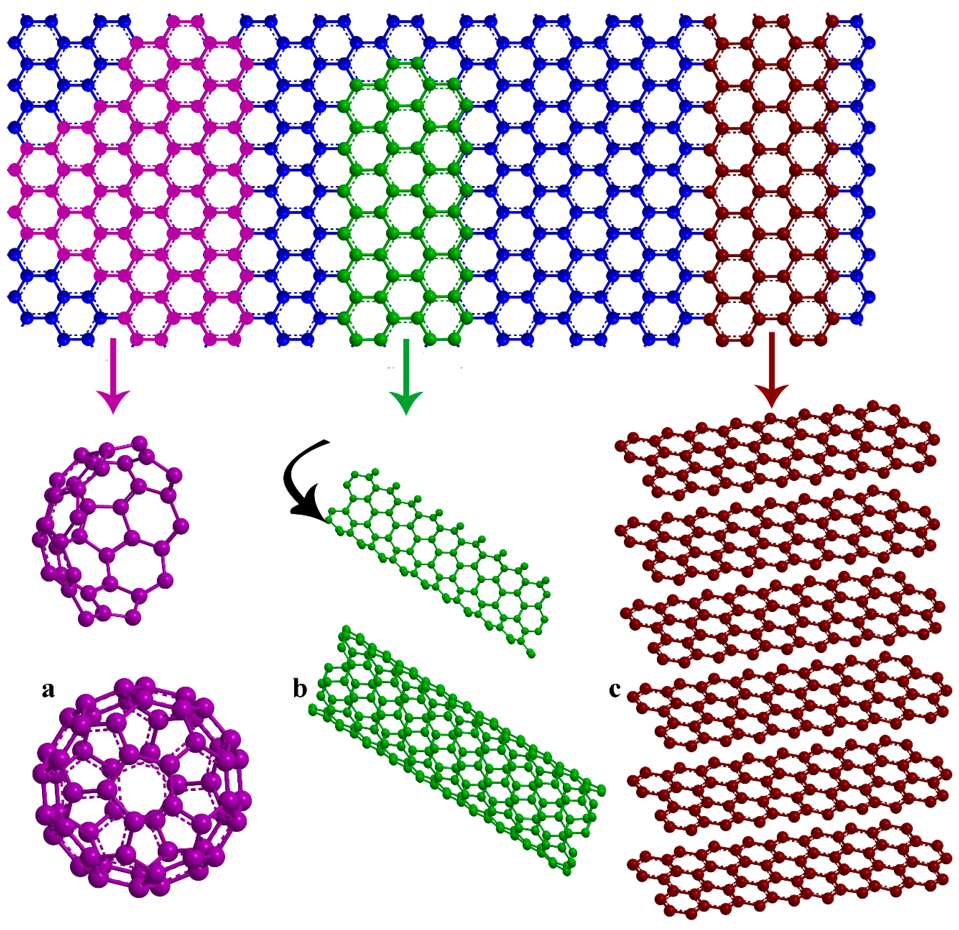
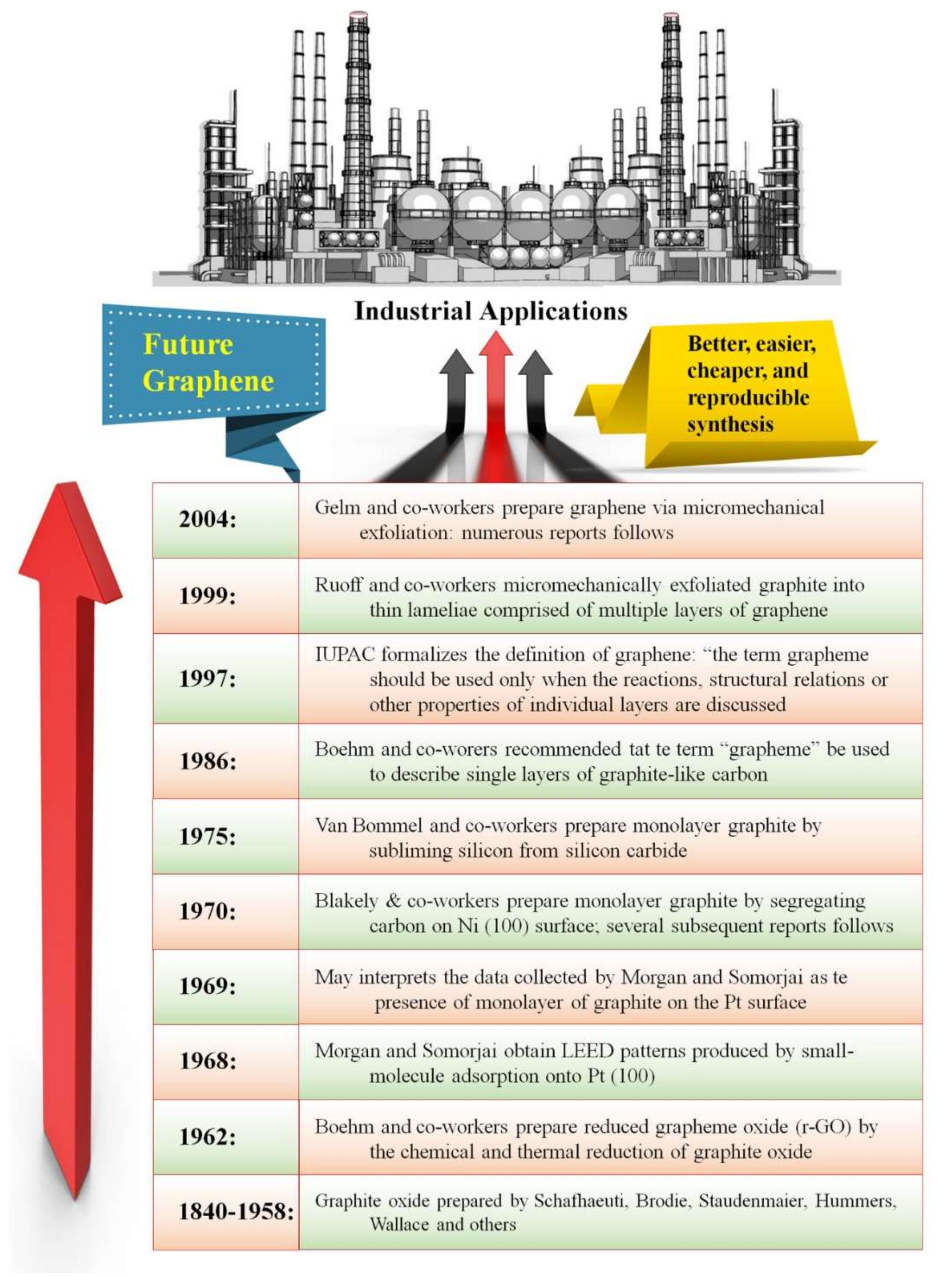
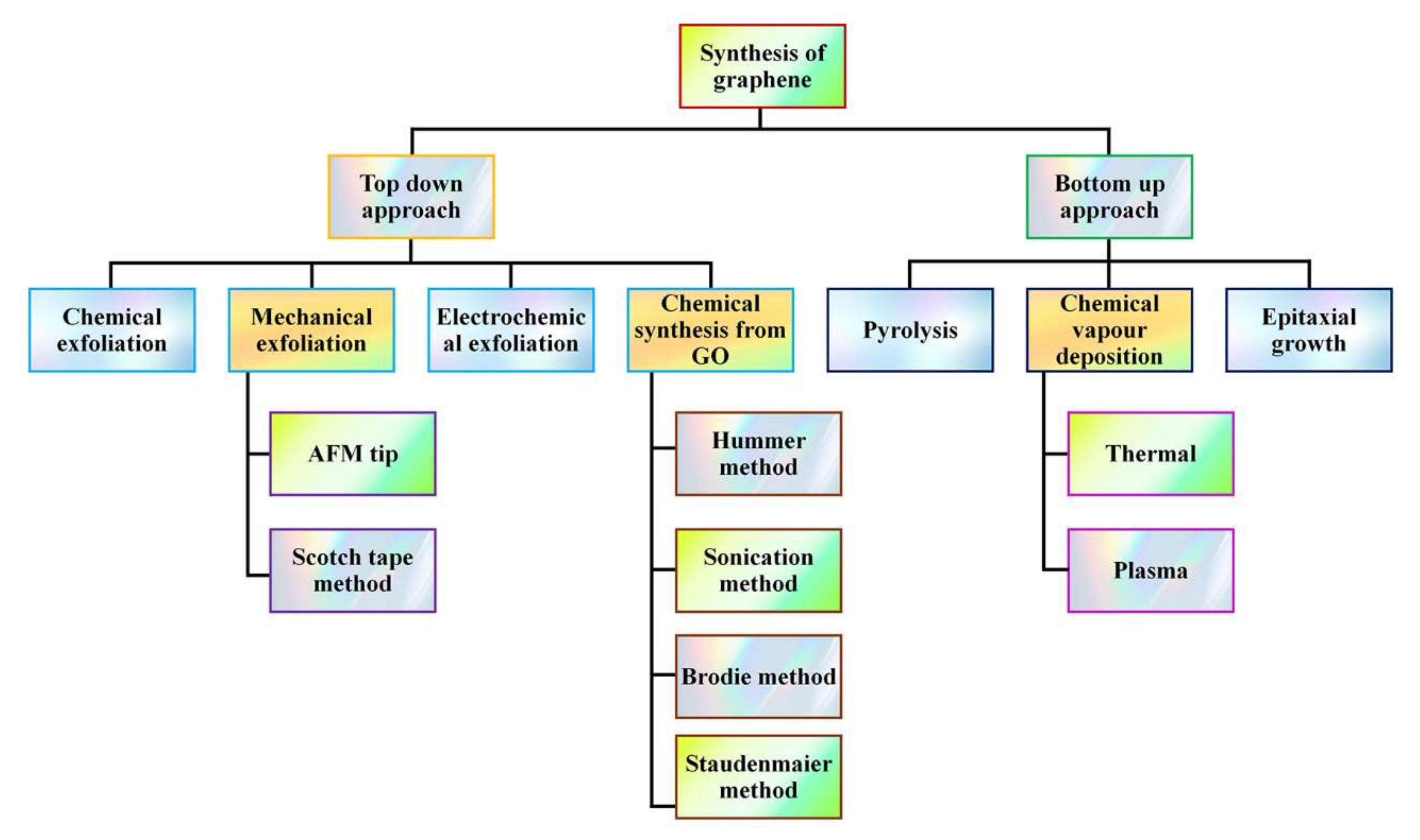

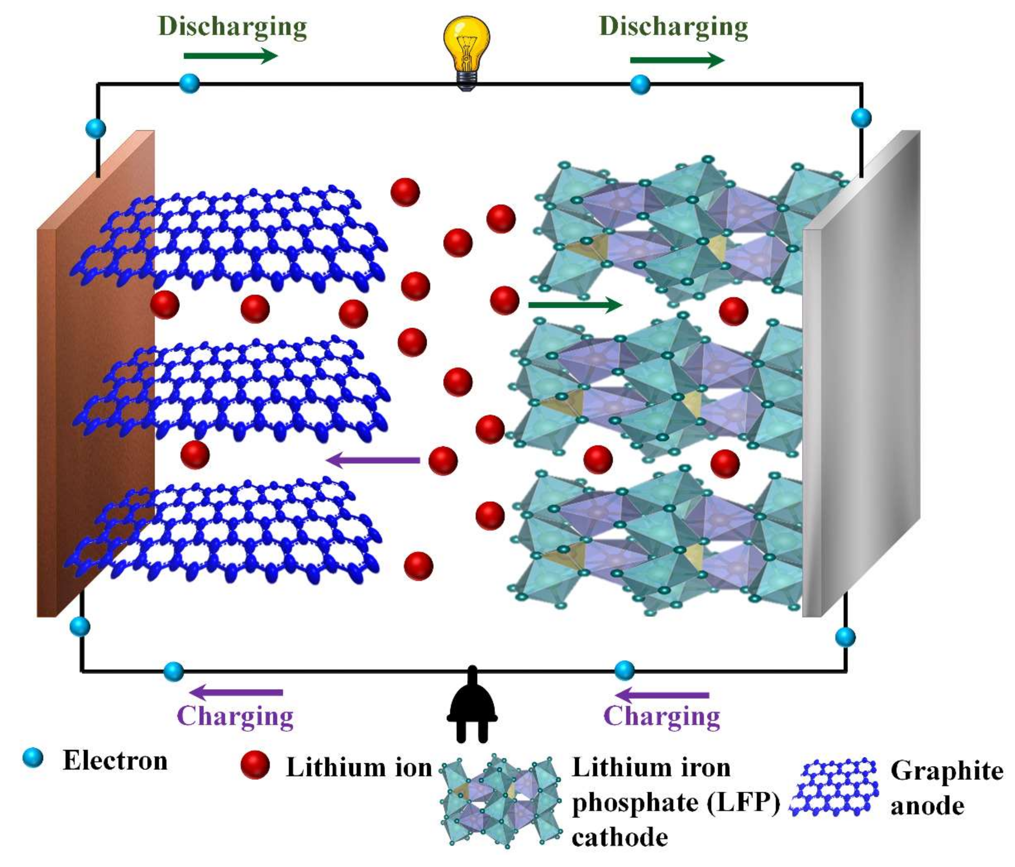

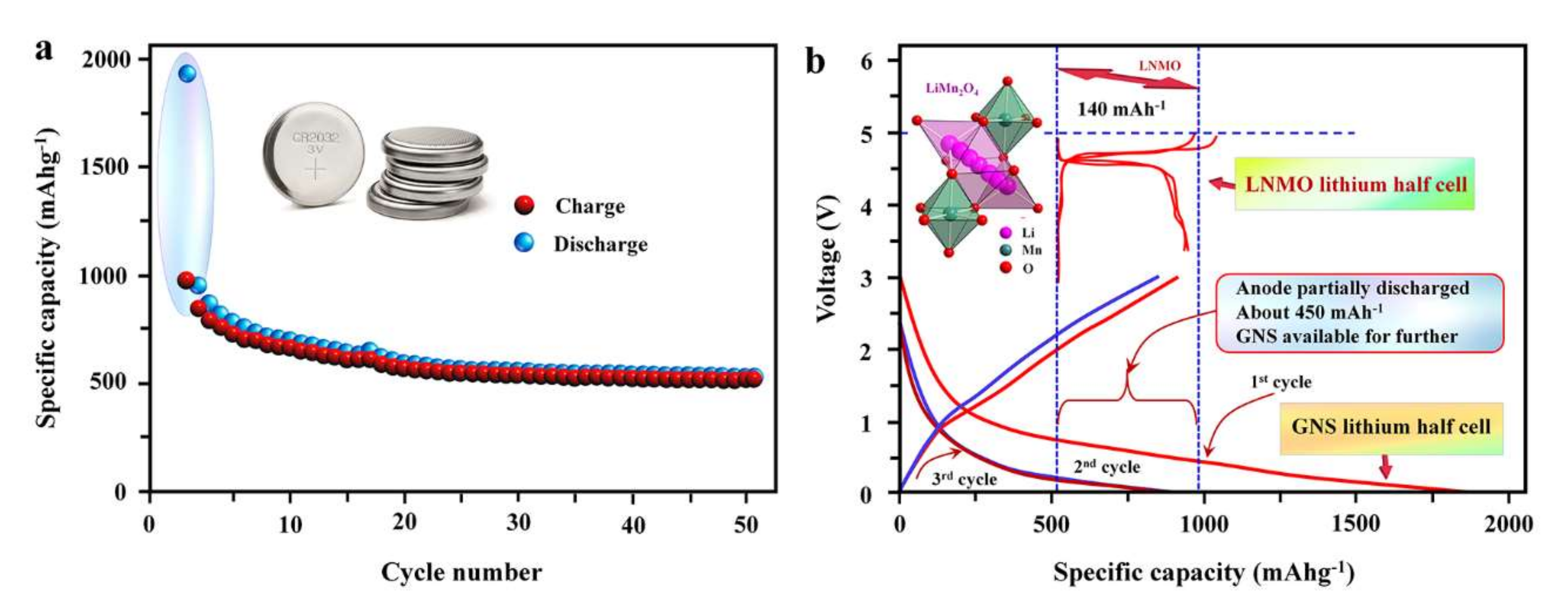
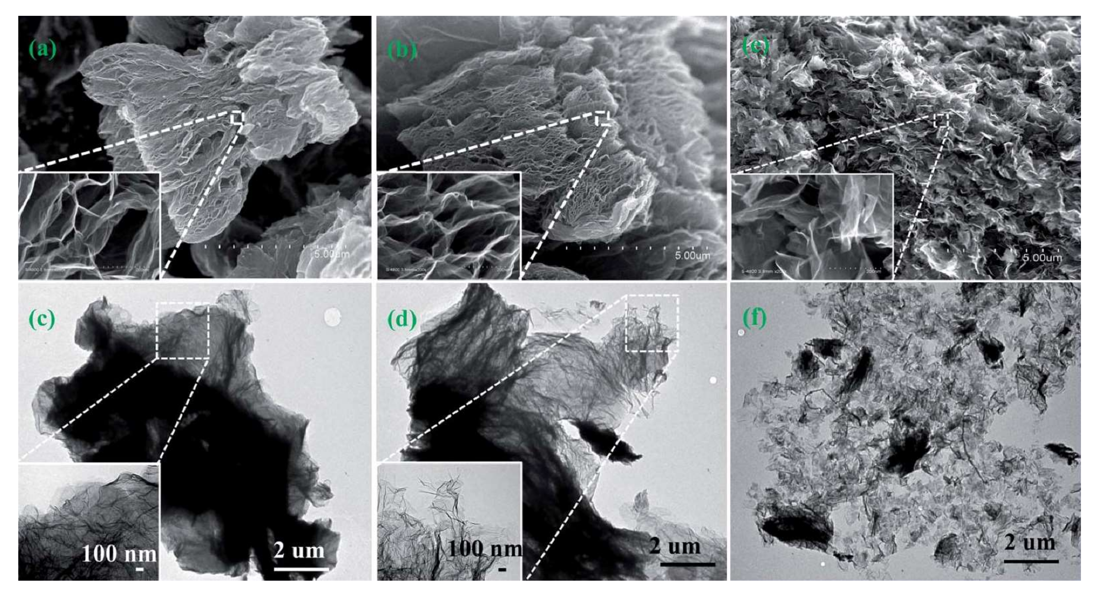
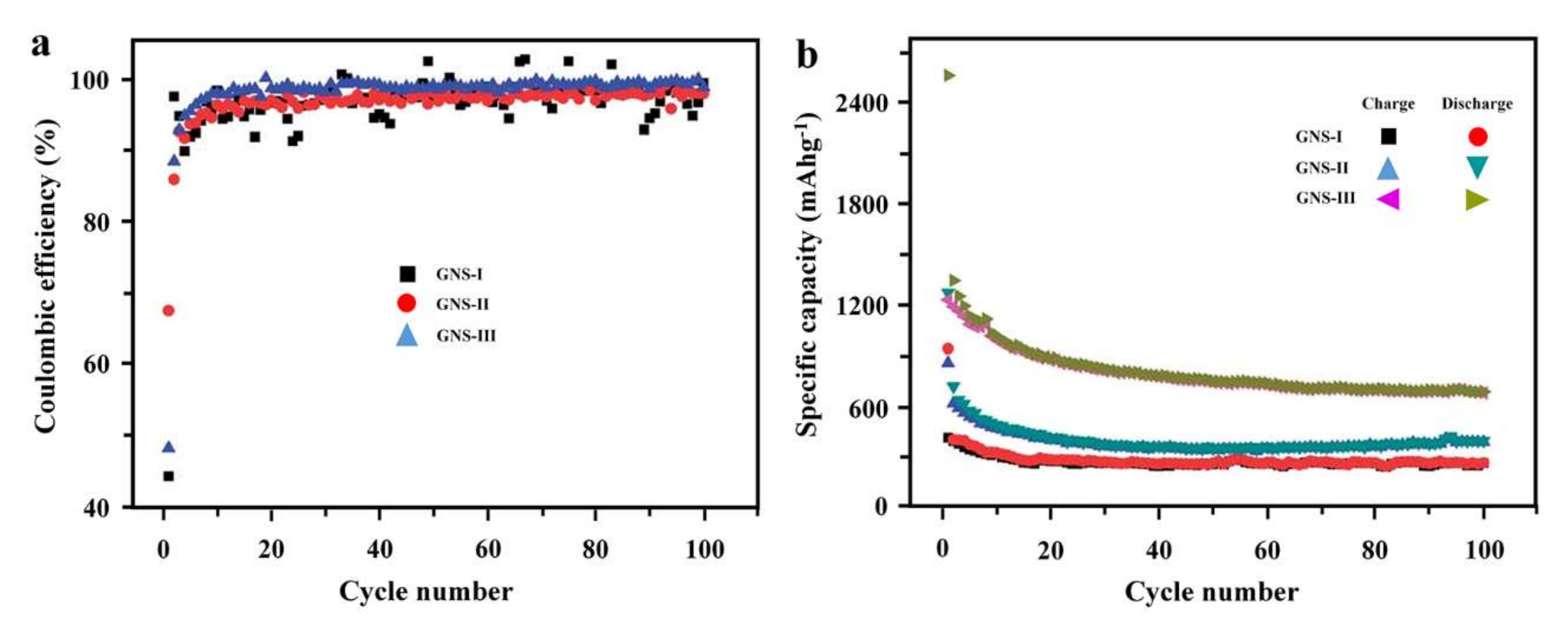

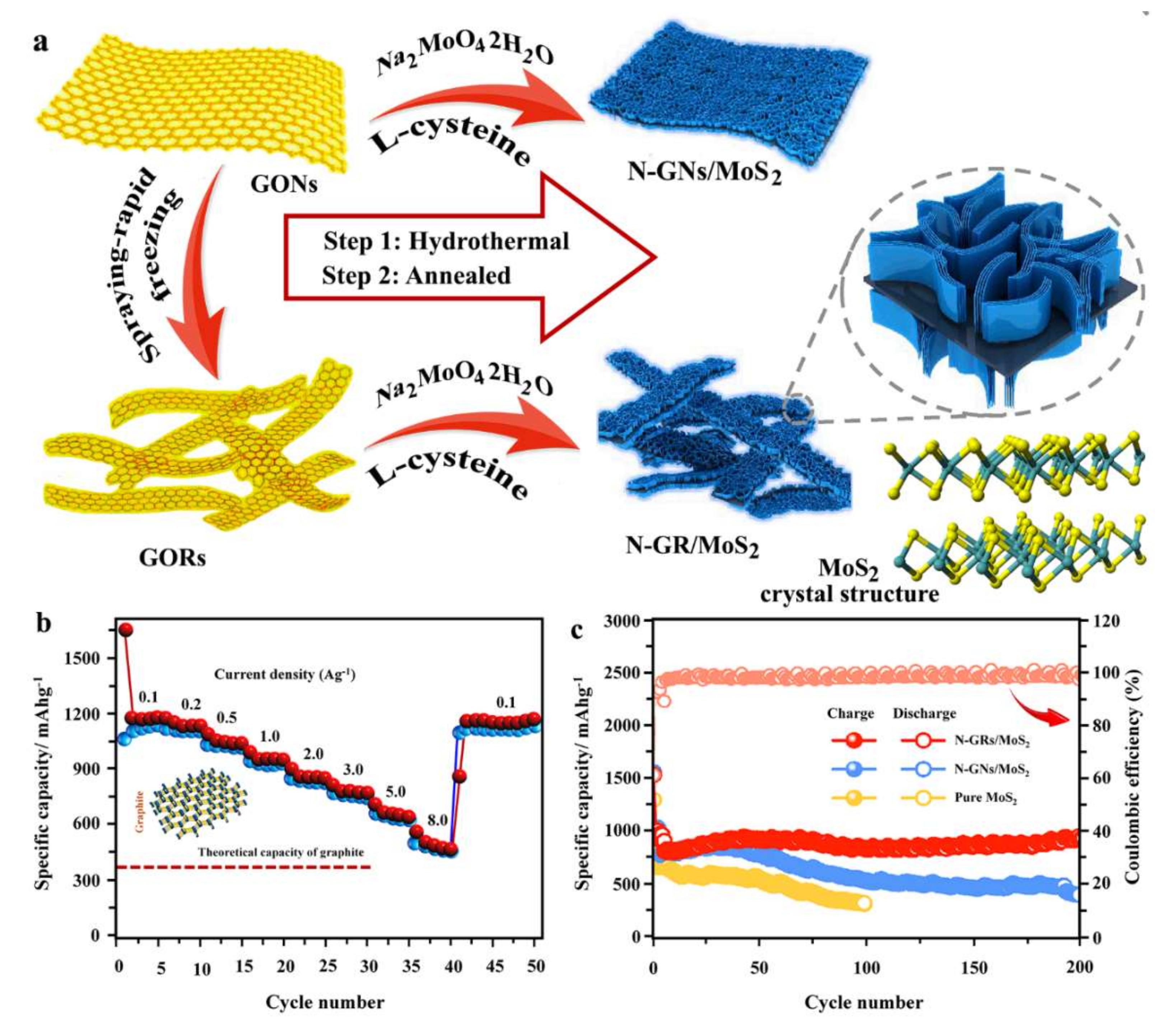
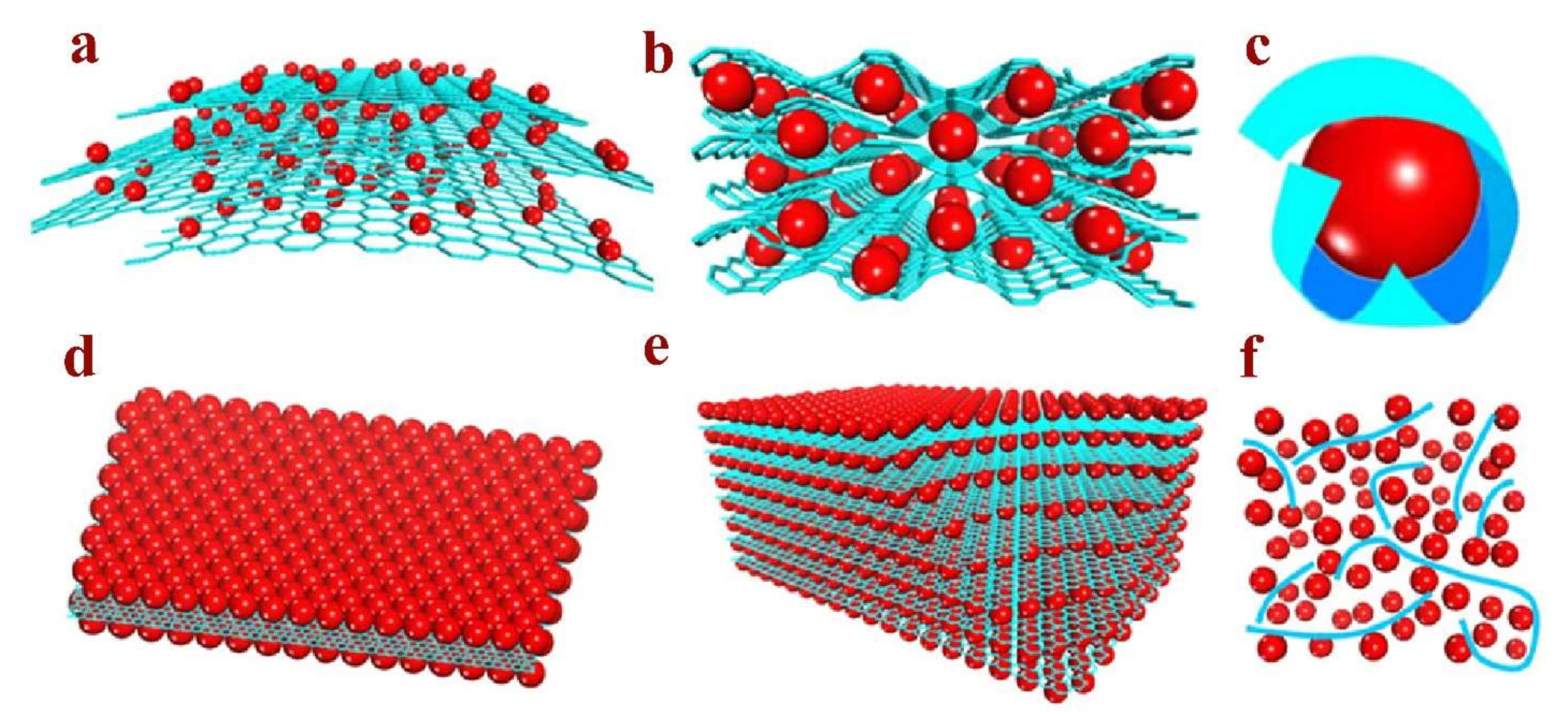


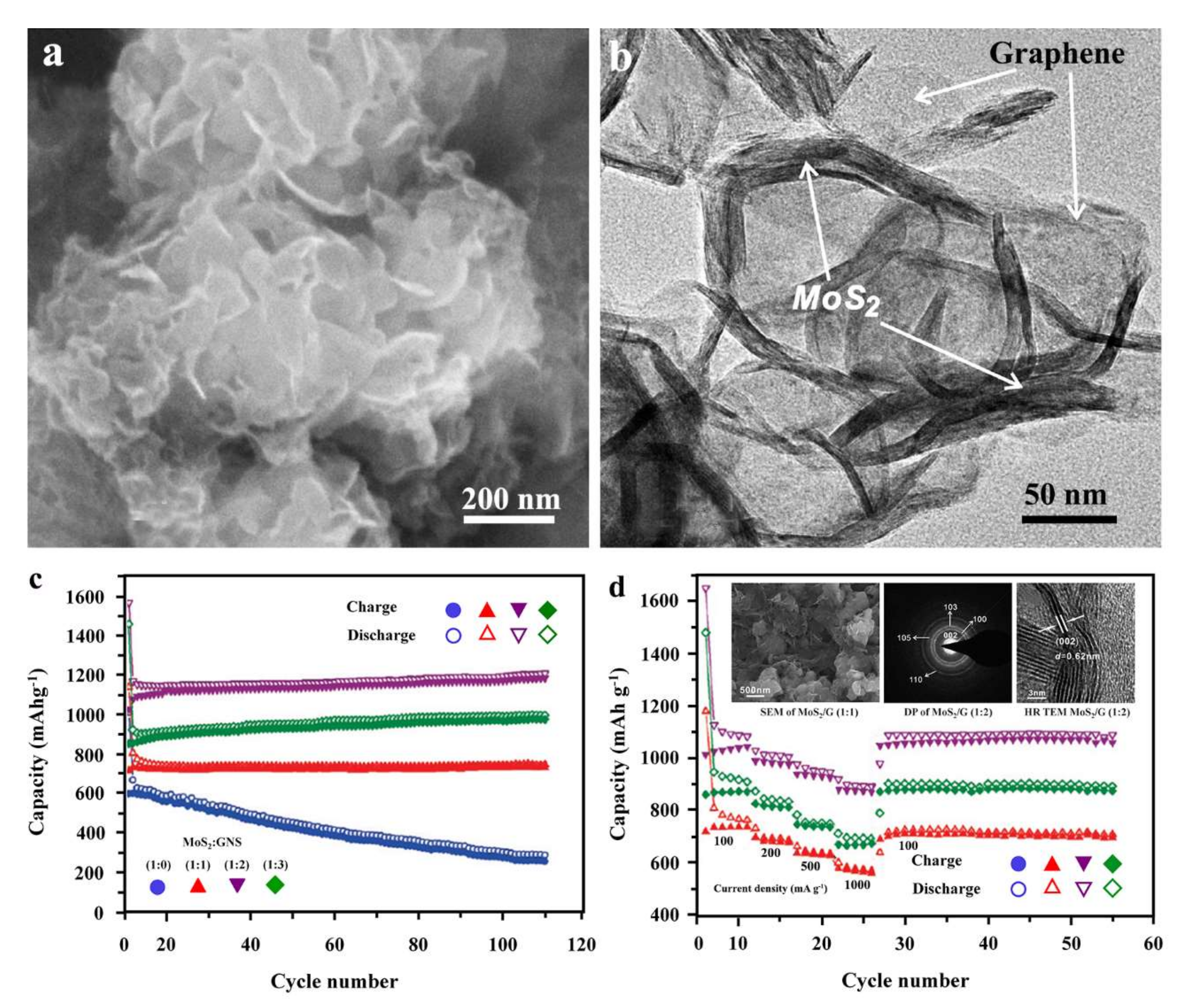
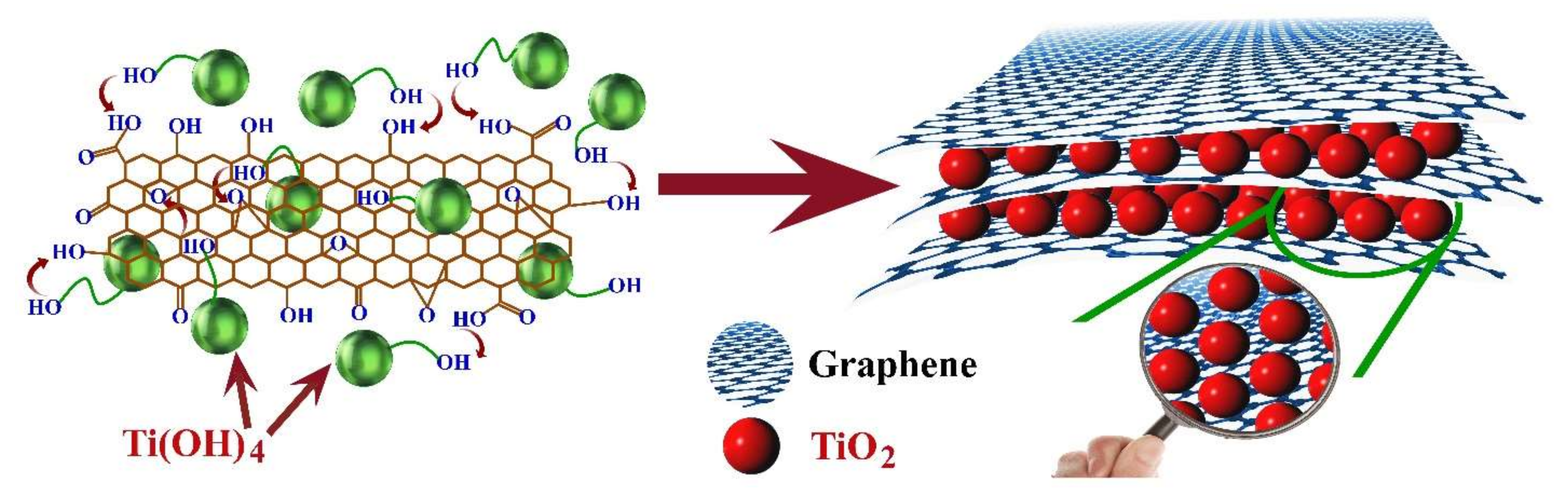
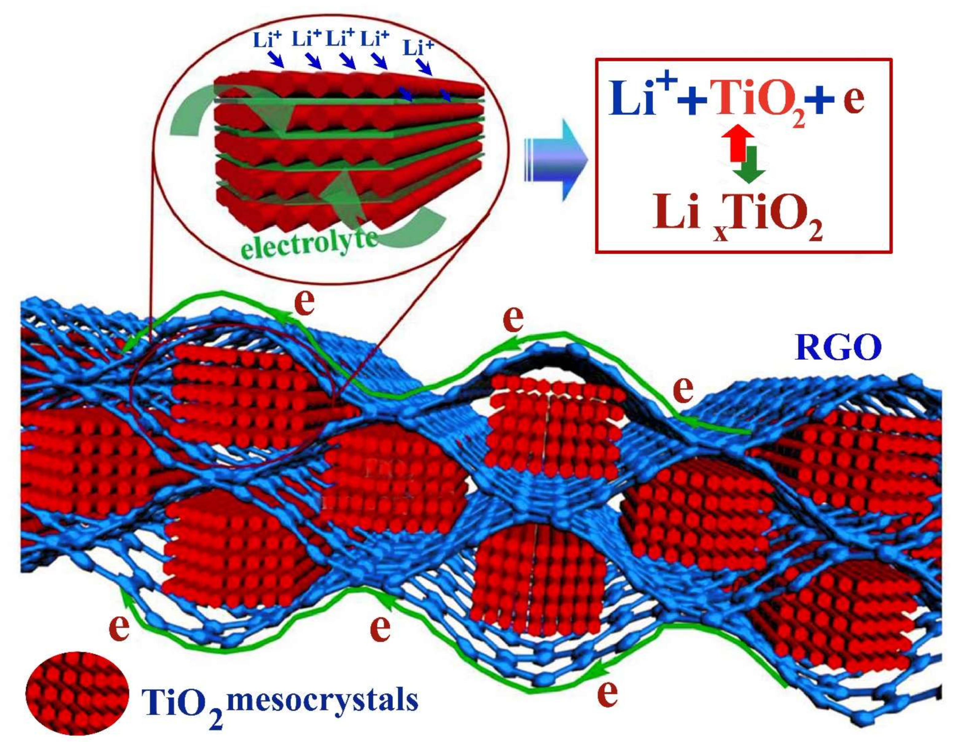
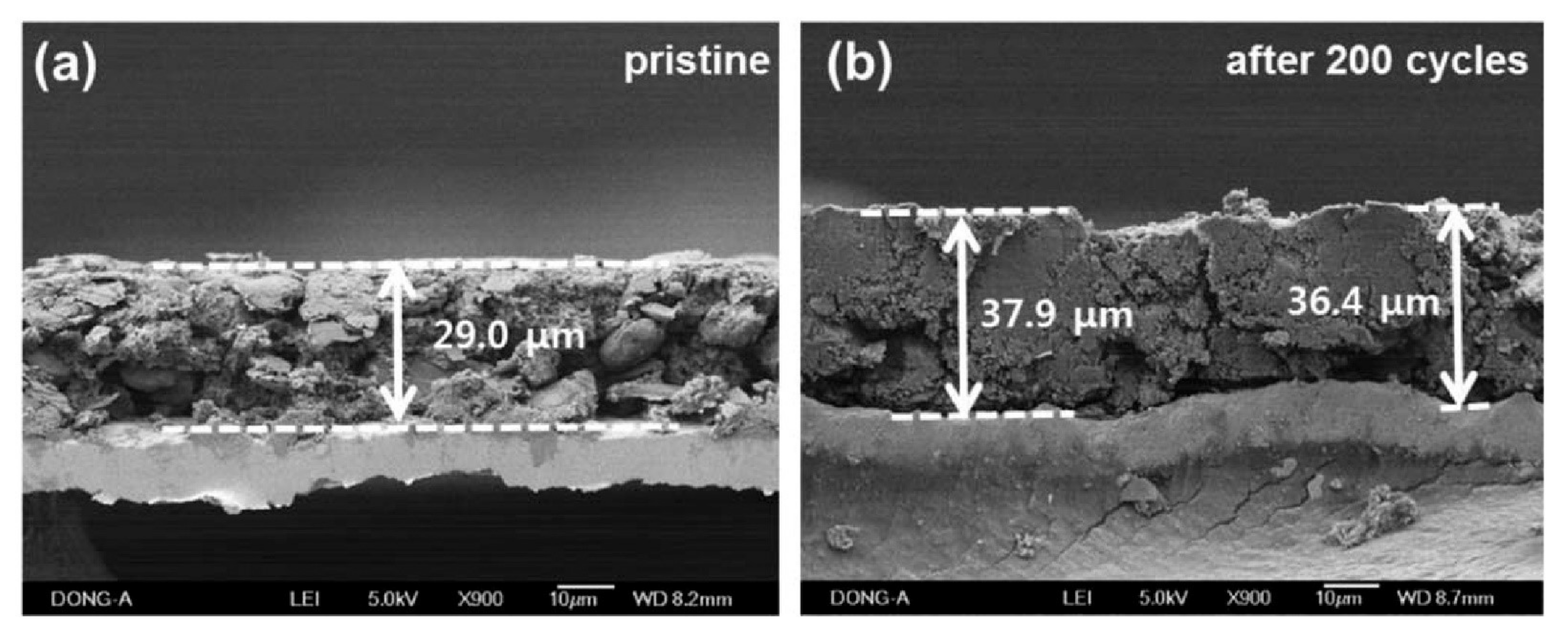
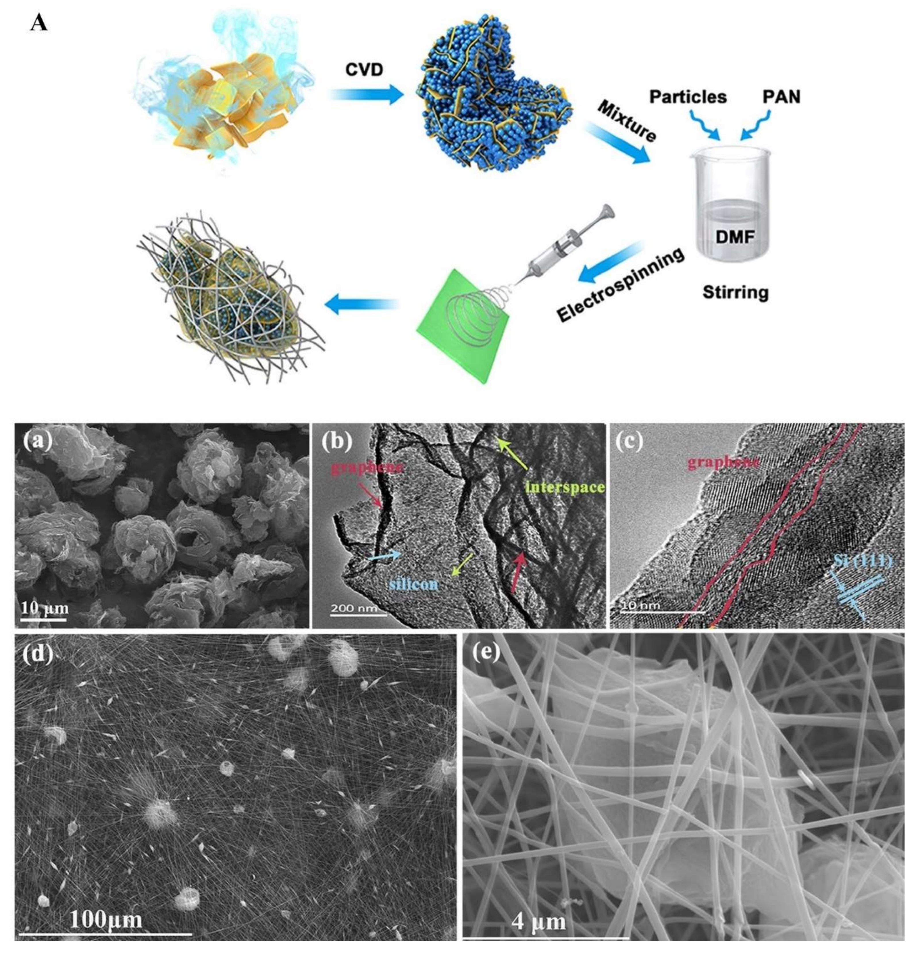
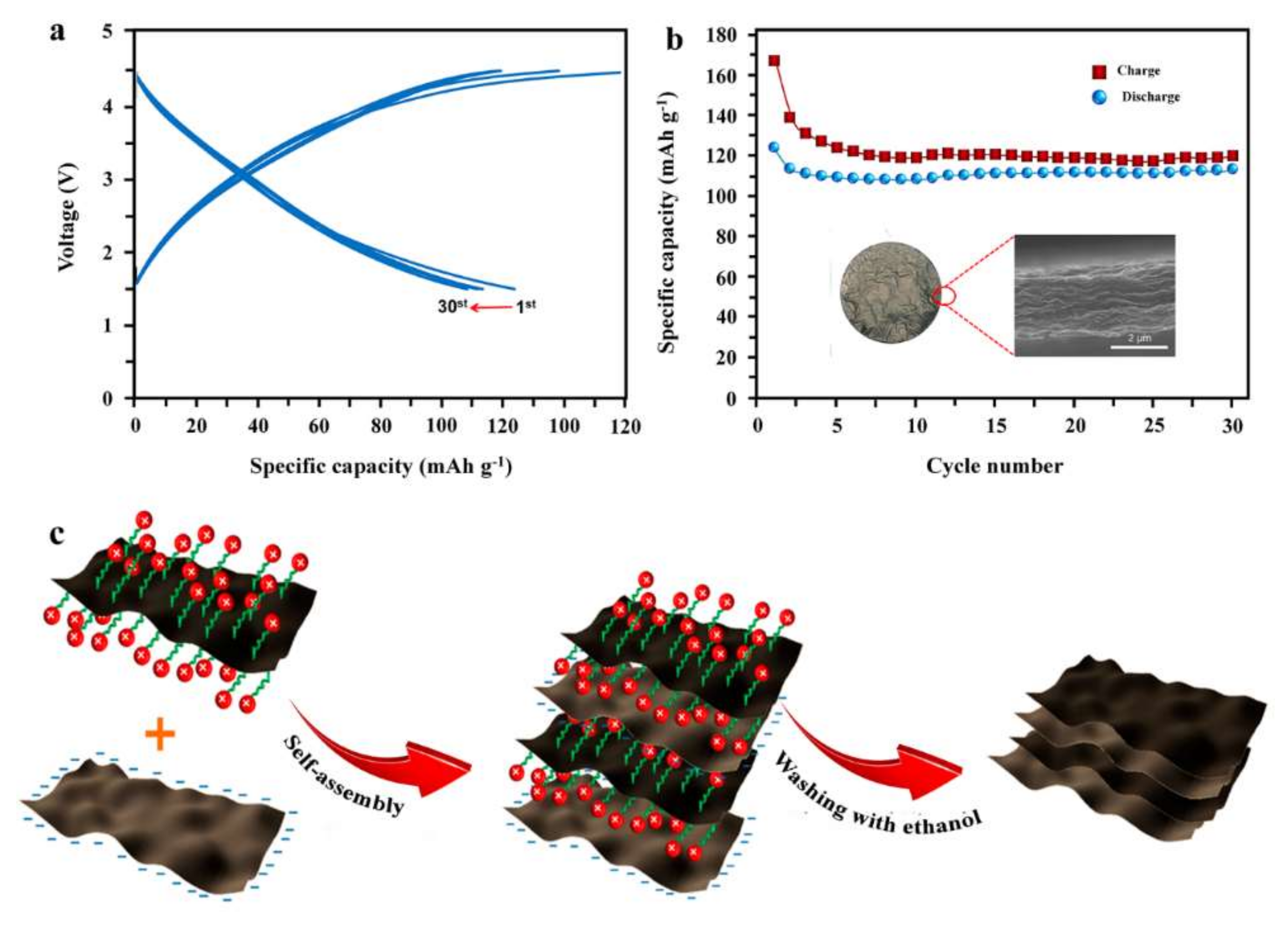
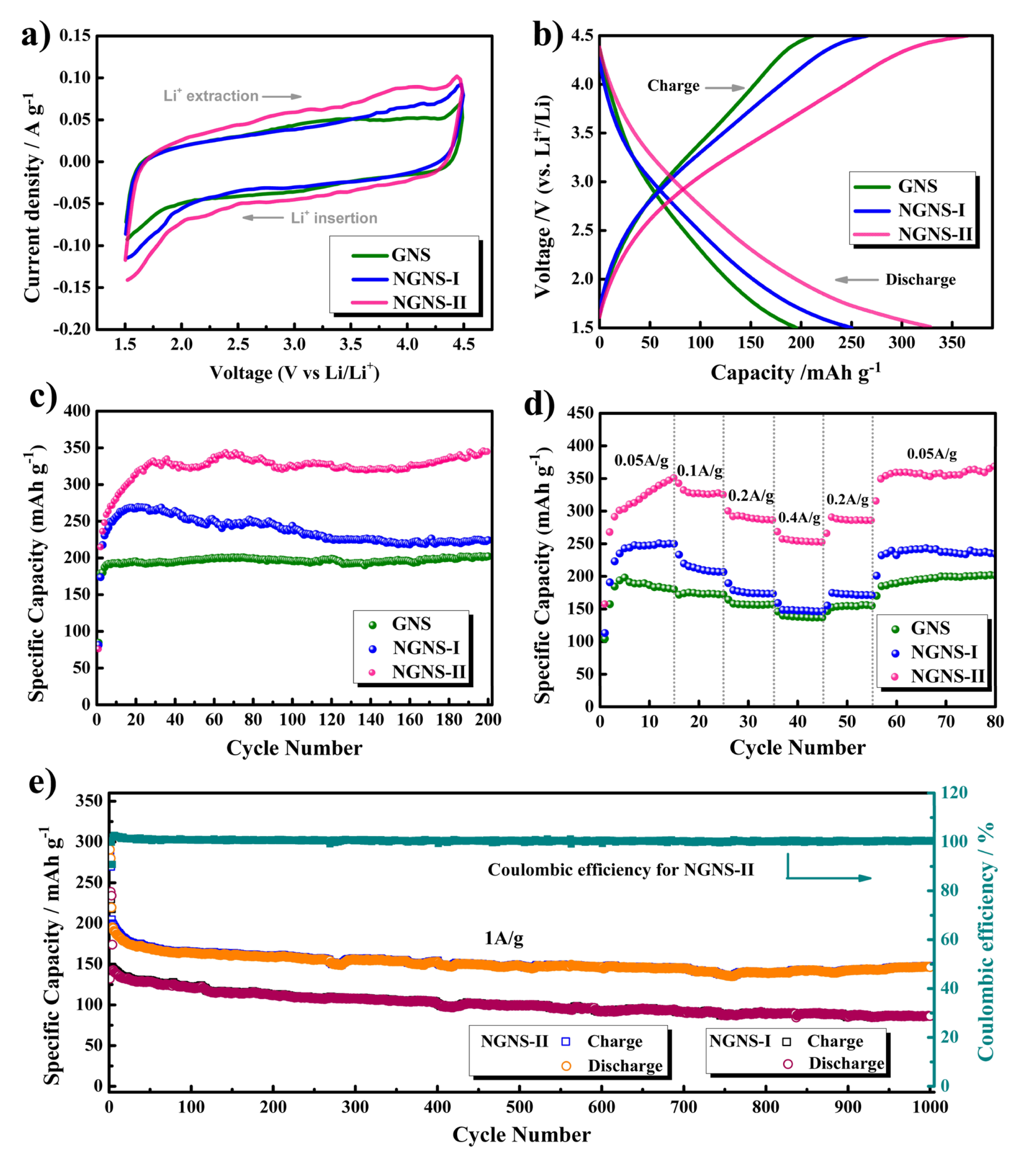
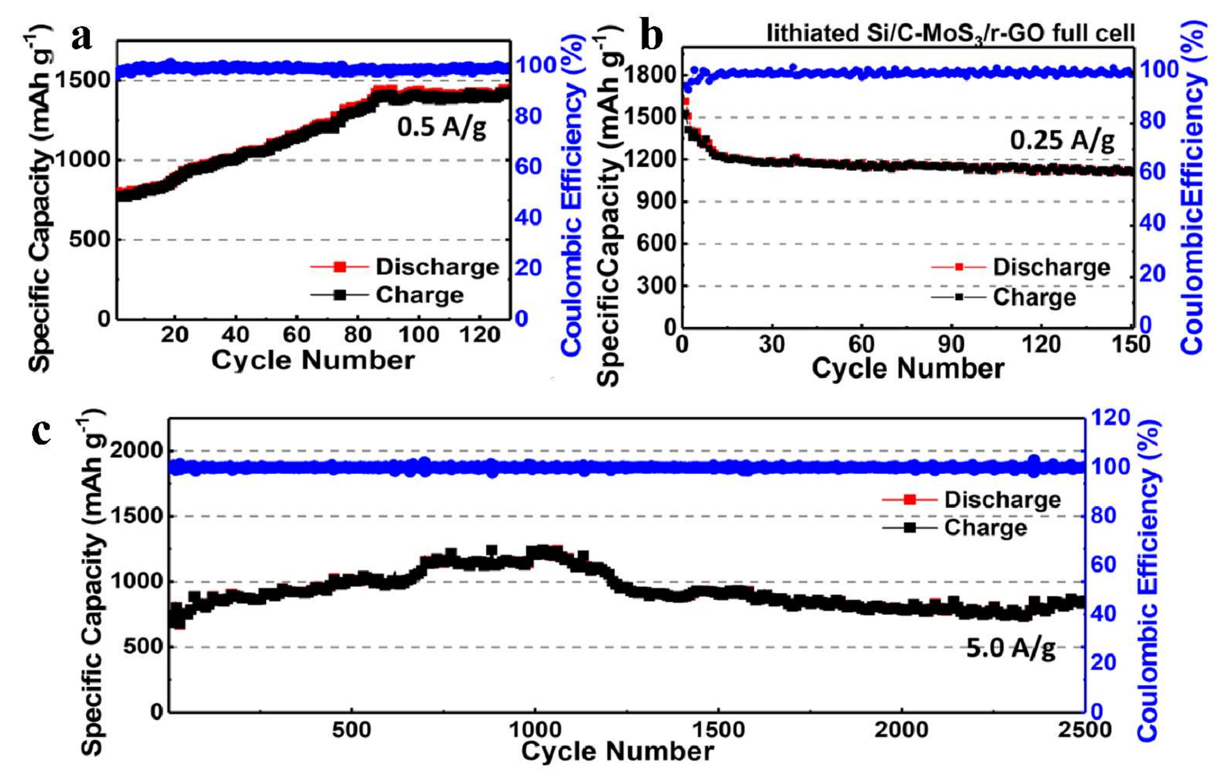
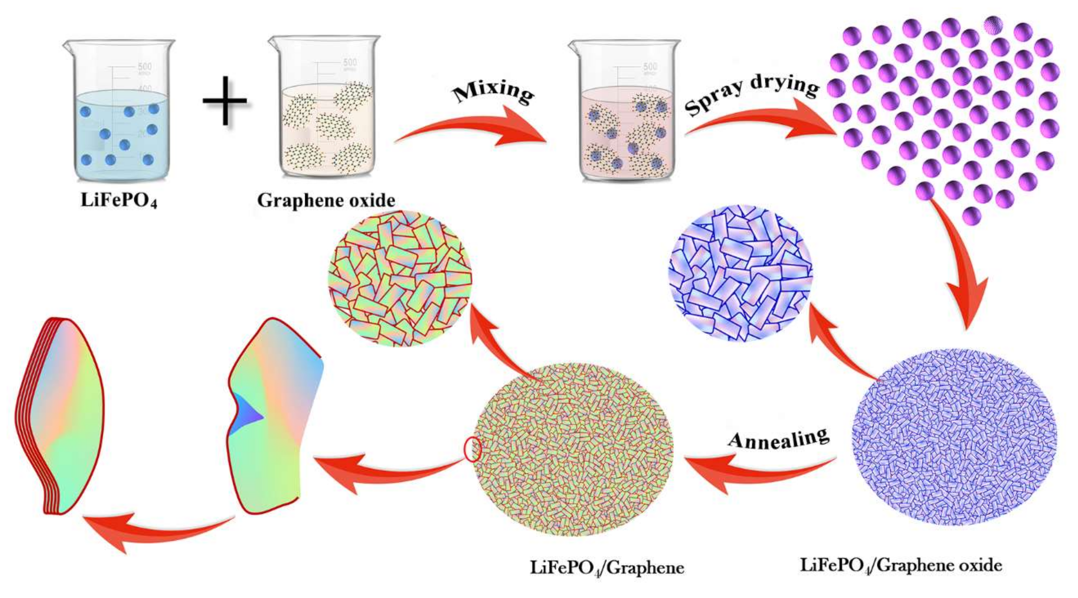

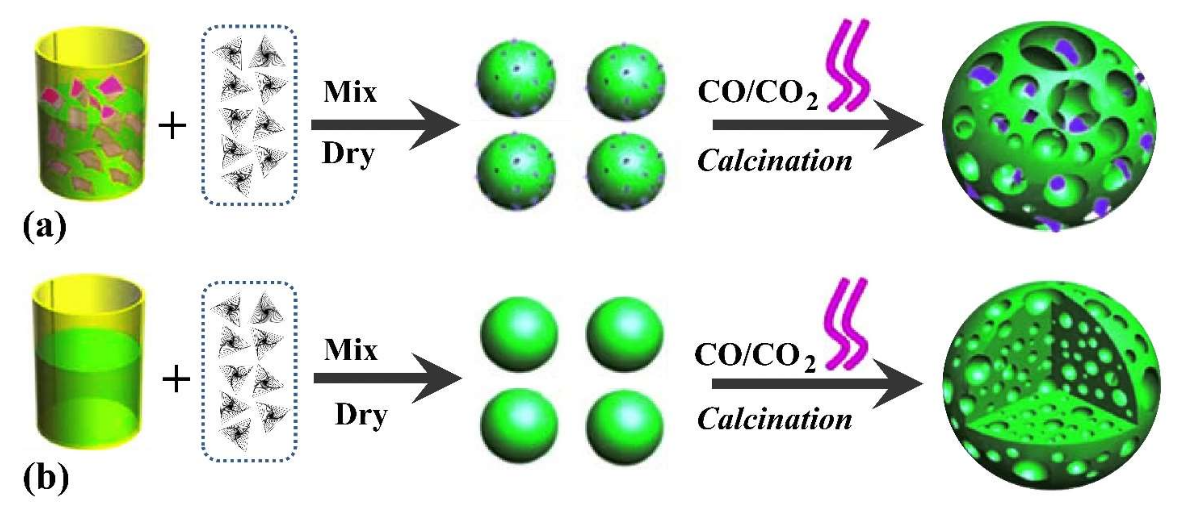

Publisher’s Note: MDPI stays neutral with regard to jurisdictional claims in published maps and institutional affiliations. |
© 2022 by the authors. Licensee MDPI, Basel, Switzerland. This article is an open access article distributed under the terms and conditions of the Creative Commons Attribution (CC BY) license (https://creativecommons.org/licenses/by/4.0/).