Article

High C-Rate Performant Electrospun LiFePO4/Carbon Nanofiber Self-Standing Cathodes for Lithium-Ion Batteries

1
Department of Chemistry, Physical Chemistry Section & C.S.G.I. (Consorzio Interuniversitario per lo Sviluppo dei Sistemi a Grande Interfase), University of Pavia, 27100 Pavia, Italy
2
Department of Physics, University of Pavia, 27100 Pavia, Italy
*
Author to whom correspondence should be addressed.
Electrochem 2024, 5(2), 223-242; https://doi.org/10.3390/electrochem5020014
Submission received: 18 April 2024 / Revised: 22 May 2024 / Accepted: 31 May 2024 / Published: 5 June 2024
(This article belongs to the Collection Feature Papers in Electrochemistry)

Abstract

:
In the present study, LiFePO4/CNF self-standing cathodes for LIBs are synthesized by electrospinning. A lower active material amount (12.3 and 34.5 wt%) is used, compared to the conventional tape-casted cathodes (70–85 wt%). The characterization techniques (XRPD, SEM, TEM, EDS, Raman spectroscopy, and thermogravimetry) confirm that the olivine-type structure of LiFePO4 is maintained in the binder-free electrodes, and the active material is homogeneously dispersed into and within the carbon nanofibers. The electrochemical investigation demonstrates that higher Li+ diffusion coefficients (1.36 × 10⁻¹¹ cm2/s) and improved reversibility are reached for free-standing electrodes, compared to the LiFePO4 tape-casted cathode (80 wt% of active material) appositely prepared for comparison. The 34.5 wt% LiFePO4 self-standing cathode displays a lower capacity fading, good reversibility and stability, enhanced capacity values at C-rates higher than 5C, and a good lifespan when cycled 1000 cycles at 1C and further cycled up to 20C, compared to the tape-casted counterpart. Notably, the improved electrochemical performances are obtained by only the 34.5 wt% of active material. The results evidence the relevant role of the CNF matrix suitable to host LiFePO4, to promote electrolyte permeation and contact with the active material, and to increase the electronic conductivity.

1. Introduction

In recent years, many efforts have been devoted to the development and search for new, renewable, and sustainable energy systems (such as solar and wind), to address the crucial issues of increasing energy demands, the consumption of traditional fossil resources, global warming, and environmental pollution [1]. Among rechargeable batteries, lithium-ion batteries (LIBs) have been demonstrated to be suitable energy storage systems: they are widely applied in small devices and represent mature technology for hybrid- and plug-in electric vehicles. LIBs display good safety, high-power density, superior energy storage capacity, and stable cycle lifetimes [2,3,4,5,6,7,8]. These appealing requisites are achieved thanks to the development of more and more well-performing active material/carbon nanocomposite electrodes [9,10,11,12].
Among the LIBs’ components, cathode materials play a crucial role, as their low electrochemical capacity (<200 mAh/g) limits the battery performance. Therefore, it is urgent to develop performant and low-cost cathode materials for LIBs. Several cathode materials, such as lithium-transition metal oxides (LiCoO2, LiNiO2, and LiMn2O4) and lithium-transition metal phosphates (LiFePO4) have been systematically investigated in recent decades, and their physicochemical properties, structure, microstructure, and lithiation–delithiation mechanism have been studied [13,14,15,16,17,18,19,20]. LiFePO4 has been demonstrated to be an appealing cathode material ever since its suitability as a host matrix for lithiation/delithiation processes was discovered [21,22,23]. It has a high theoretical capacity of 170 mAh/g, and it is low-cost, safe, environmental-benign, and non-toxic [24]. LiFePO4 displays an olivine-type structure, and it is thermally stable at up to 270 °C. Despite the aforementioned appealing features, the electrochemical performances of LiFePO4 are limited by its poor electronic conductivity (10−6 to 10−10 S/cm) [25] and inadequate Li-ion diffusivity (about 10−14 cm2 s−1) [26]. These drawbacks can be solved by several strategies, such as surface decoration [27,28,29], the doping/substitution of the transition metal ion [30,31,32], morphology control, and particle size reduction [33,34].
In the case of electrode materials, both ionic and electronic conductivities are crucial factors affecting the electrochemical performance. Among the conducive carbon additives used to enhance the electronic conductivity, reduced graphene oxides (r-GO), carbon nanotubes (CNTs), and carbon nanofibers (CNFs) represent a good choice. In particular, CNFs exhibit high electronic conductivity and a one-dimensional carbon structure, which favors the easy access of electrolytes. Based on these features, several active material/CNF composites have been synthesized and investigated, and flexible/free-standing cathodes with enhanced electrochemical performance were fabricated [35,36], based on lithium transition metal oxides [37,38], phosphates [39,40,41,42], and silicates [43,44,45].
The electrospinning technique has been recently regarded as a suitable strategy for preparing free-standing electrodes for LIBs and SIBs [25,46,47,48,49,50]. Self-standing electrodes represent the suitable choice for power sources of flexible electronic equipment and wearable devices [51,52,53,54]. They are pliable and lightweight, as the use of heavy current collectors and insulating binders required in conventional slurry-casting electrodes is avoided. Active material/carbon nanofiber (CNF) hybrids can be easily synthesized by electrospinning, and self-standing electrodes with enhanced electrochemical performances are obtained: CNFs offer a highly porous 3D network that hosts the active material, allowing for the easy permeation of the electrolyte and exhibiting excellent electronic conductivity and mechanical properties. The continuous conductive network and the interconnected porosity give rise to faster electron and ion transport, compared to the traditional stacked 1D electrode architecture [55].
As concerns LiFePO4, promising electrochemical performances have been obtained by preparing LiFePO4–carbon nanofibers composites. The effective gain in specific capacity and cycling performance for conventional tape-casted cathodes of LiFePO4/carbon nanofibers synthesized by dry mixing or electrospinning [26,56,57] and for electrospun free-standing electrodes [25,47,48] has been demonstrated. In the latter case, the further enhancement of the electrochemical performances has been obtained by synthesizing LiFePO4/carbon nanofibers enriched with other carbonaceous sources, such as reduced graphene oxide (rGO) or multi-walled carbon nanotubes (MWCNTs) [58,59]. The procedures adopted to synthesize the electrospun self-standing electrodes are based on (i) LiFePO4 precursor additions to the polymer solution before electrospinning, (ii) the electrospinning of the CNFs, and the addition of the LiFePO4 precursors by dip–drop coating, or (iii) the dispersion of active material into the polymer solution to be electrospun. The active material’s amount typically approaches that used for conventional tape-casted electrodes: 70–85 wt%.
Based on the above-mentioned advantages of the CNF matrix to host LiFePO4 active material, we synthesize and characterize self-standing LiFePO4/CNF cathodes with lower LiFePO4 amounts (10 and 30 wt%) to investigate if good electrochemical performances can be achieved at high C-rates and cycle indexes, also by using low active-material contents. The free-standing electrodes are prepared by the simplest electrospinning procedure, and commercial LiFePO4 is used. LiFePO4 was added to a polyacrylonitrile in a N, N-dimethylacetamide solution and electrospun. The obtained sheets underwent stabilization and carbonization processes, and the free-standing cathodes were obtained. They were characterized by X-ray powder diffraction and Rietveld structural and profile refinement, Scanning Electron Microscopy, energy dispersive spectroscopy, transmission electron microscopy, Raman spectroscopy, and thermogravimetry to investigate the structure, morphology, and active material dispersion of CNFs. The electrochemical performances of the LiFePO4/CNFs and LiFePO4 tape-casted (80 wt% of active material) cathodes are compared. A scheme of the synthetic approaches used for the electrodes’ preparation is shown in Figure 1. Improved capacity at high C-rates and cell lifespan are achieved by only 30 wt% of active material being loaded into the CNF matrix.

2. Materials and Methods

2.1. Materials

All the chemicals employed were reagent-grade or of a higher quality: lithium iron phosphate (LiFePO4; Aldrich 759546, Milano, Italy), 1 M lithium hexafluorophosphate in ethylene carbonate/diethylene carbonate EC/DEC (1:1 v:v) electrolyte (Aldrich 746746, Milano, Italy), carbon acetylene black powder (Alfa Aesar 39724, Aldrich, Milano, Italy), Poly(vinylidene fluoride) (PVdF; Kynar; Aldrich, Milano, Italy), 1-Methyl-2-pyrrolidone (NMP; Aldrich 328634, Milano, Italy), Polyacrylonitrile (PAN: (C3H3N)n; Aldrich 181315, Milano, Italy), and N,N-dimethylacetamide (DMAc: CH3CON(CH3)2; Aldrich D137510, Milano, Italy).

2.2. Synthesis

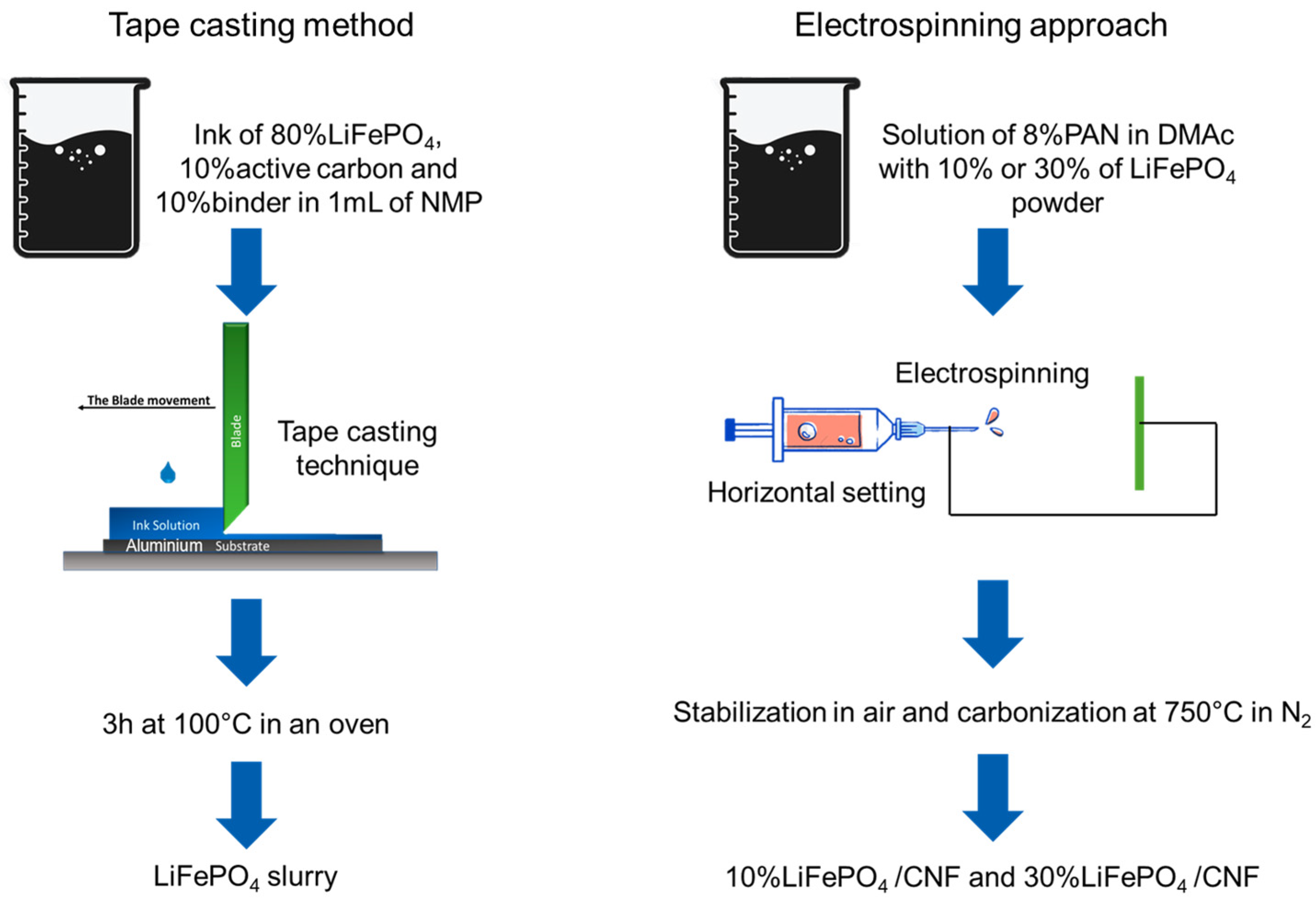
2.2.1. LiFePO4 Self-Standing Cathodes

Two self-standing LiFePO4/CNF cathodes containing the 10 and 30 wt% of active material (commercial LiFePO4) were prepared, and hereafter named 10%LiFePO4/CNF and 30% LiFePO4/CNF. In total, 0.188 g (10 wt%) or 0.564 g (30 wt%) of commercial LiFePO4 was dispersed into 25 mL of DMAc, sonicated for 1 h, added to 1.88 g of PAN (8 wt%), and stirred at 60 °C overnight. The obtained suspension was electrospun (EF050—Starter Kit Electrospinning of SKE Research Equipment, C/O Leonardino S.r.l, Bollate, Italy) with horizontal settings at the following operating conditions: 10.5 mL dispersion, 3.5 mL/h flow, 16 Gauge needle, applied voltage 18 kV, needle–collector distance 18 cm, deposition time 3 h, and controlled humidity lower than 20%. The obtained sheets were removed from the aluminum support and stabilized in air for 30 min at 100 °C, 30 min at 200 °C, and finally 2 h at 260 °C (heating ramp: 5 °C/min). Finally, the fibers were carbonized at 750 °C for 2 h (heating ramp: 10 °C/min) in a nitrogen atmosphere. A scheme of the process is shown in Figure 1.
A pure CNF sample was also synthesized by electrospinning 8 wt% PAN in a DMAc solution for comparison with self-standing electrodes’ characterization.

2.2.2. Tape-Casting Cathode

The 80 wt% of LiFePO4, 10 wt% acetylene carbon, and 10 wt% PVdF binder (Kynar) were dispersed in NMP [60] and stirred for 2 h. The slurry was tape-casted (Doctor Blade coating technique) on aluminum foil (current collector) and dried at 100 °C for 3 h. A scheme of the process is shown in Figure 1. The electrochemical performances of the tape casting cathode and the self-standing electrodes will be compared and discussed.

2.3. Cell Assembly

The Swagelok-type cells are assembled in an Argon-filled dry box (M. Braun H2O < 0.1 ppm O2 < 0.1 ppm). In total, 1 M LiPF6 in EC:DEC (1:1 v:v) is used as the electrolyte (1 mL), the diameter of the cathodes is 1 cm with a thickness of about 180 µm, and 30 µm for self-standing and tape-casted, respectively, and lithium foil is used as a counter-electrode (1 cm diameter).

2.4. Characterization Techniques

A Bruker D5005 diffractometer (Bruker, Karlsruhe, Germany) is used for X-ray powder diffraction (XRPD) data collection. Use was made of the Cu Kα radiation, curved graphite monochromator on the diffracted beam, and scintillation detector. The data collection is performed in the 16–80° 2θ range, step size 0.03°, and counting time of 22 s/step. The TOPAS 3.0 software [61] is used to apply the Rietveld refinement to the commercial LiFePO4 and LiFePO4/CNF samples.
A Zeiss EVO MA10 (Carl Zeiss, Oberkochen, Germany) microscope, equipped with an energy dispersive detector for the EDS analysis, is used to collect SEM micrographs on gold-sputtered samples (20 kV, secondary electrons images, and working distance 8.5 mm), and to obtain the element distribution maps of the samples.
A JEOL JEM-1200EXIII equipped with a TEM CCD camera Mega View III transmission electron microscope is used for TEM analysis. The samples are dispersed in water; a drop of about 0.7 μL is deposited on the Ni grid and dried.
Thermogravimetric data are collected with a TGA Q5000 IR apparatus interfaced with a TA 5000 data station (TA Instruments, Newcastle, DE, USA). The measurements are performed in the 25–750 °C temperature range in air (heating rate: 10 °C/min).
Raman measurements are performed at room temperature using an automated and integrated confocal microRaman spectrometer, XploRA Plus HORIBA Scientific, equipped with an Olympus microscope BX43. Laser red light at 638 nm is used for excitation, tuning the 90 mW incident power by a set of neutral filters with different optical densities. The spectrometer is equipped with a motorized xy stage, on which the investigated samples are positioned. The spectral resolution is about 2 cm−1. An open electrode CCD camera, with a multistage Peltier air-cooling system, is used as a detector. The measurements are performed using a 50x magnification objective with a spatial resolution of the order of 4 microns. The spectra are acquired with a mean integration time of about 20 s and a number of accumulations equal to 10. All the reported data are obtained as the average spectrum, sampling the materials in several different regions.
The electrochemical performances are investigated using a Swagelok cell at ambient temperature in the 2.5–4.0 V voltage range. An Autolab PGSTAT30 potentiostat (Eco Chemie) is used for cyclic voltammetry (CV). The CV data are processed with GPES V4.9 software. A Neware-4000BTS Battery Testing System at different current rates is used to obtain the galvanostatic charge/discharge profiles. The electrochemical impedance spectroscopy (EIS) measurements were performed using an Autolab PGSTAT30 potentiostat (Eco Chemie). The EIS spectra were acquired at OCV in the 105–10−2 Hz frequency range with an amplitude potential of 1 mV.

3. Results and Discussion

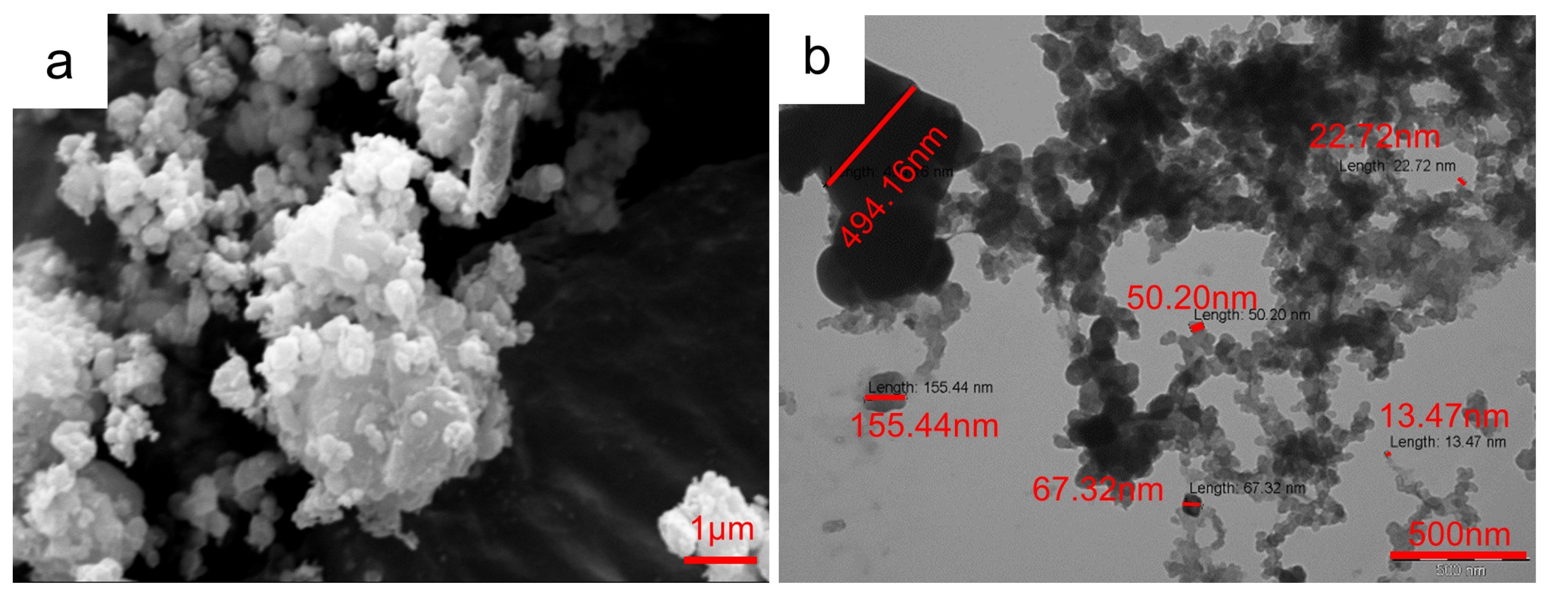
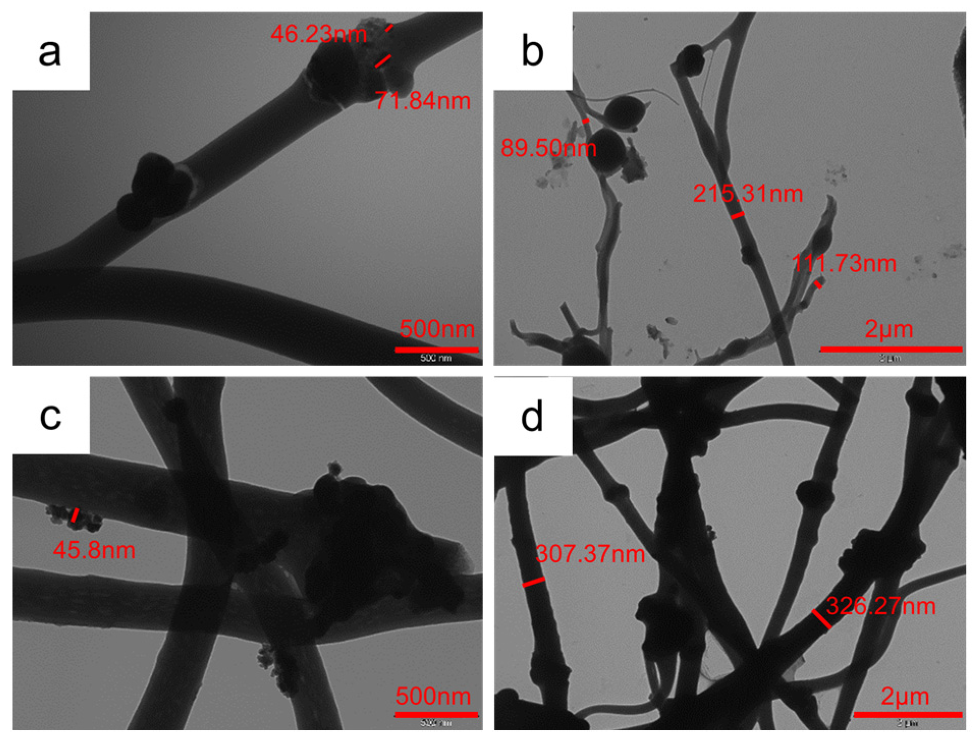
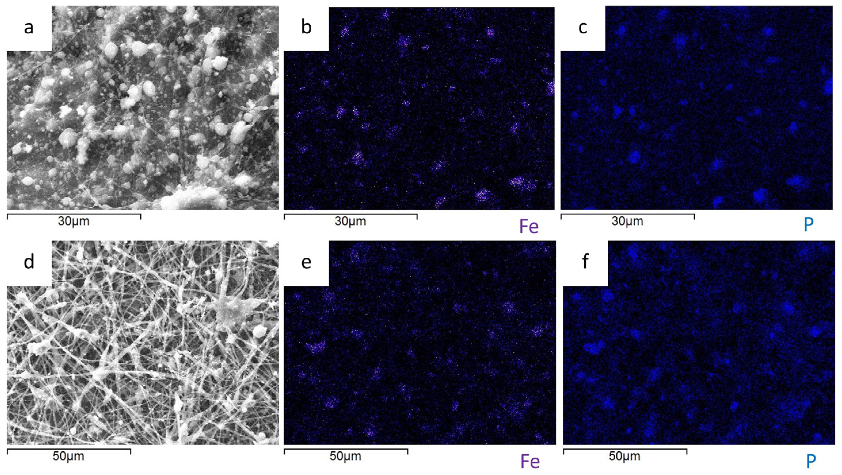
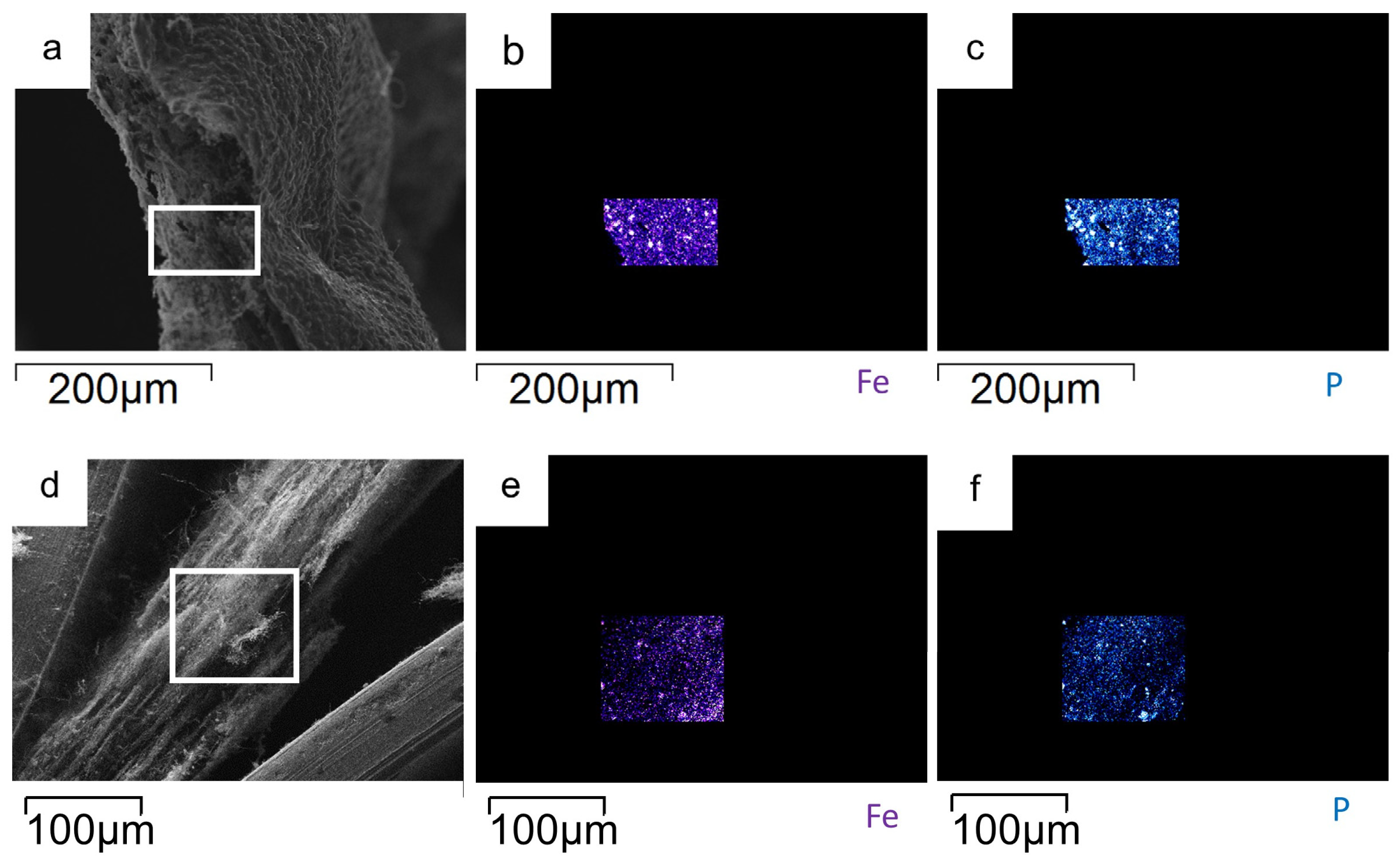
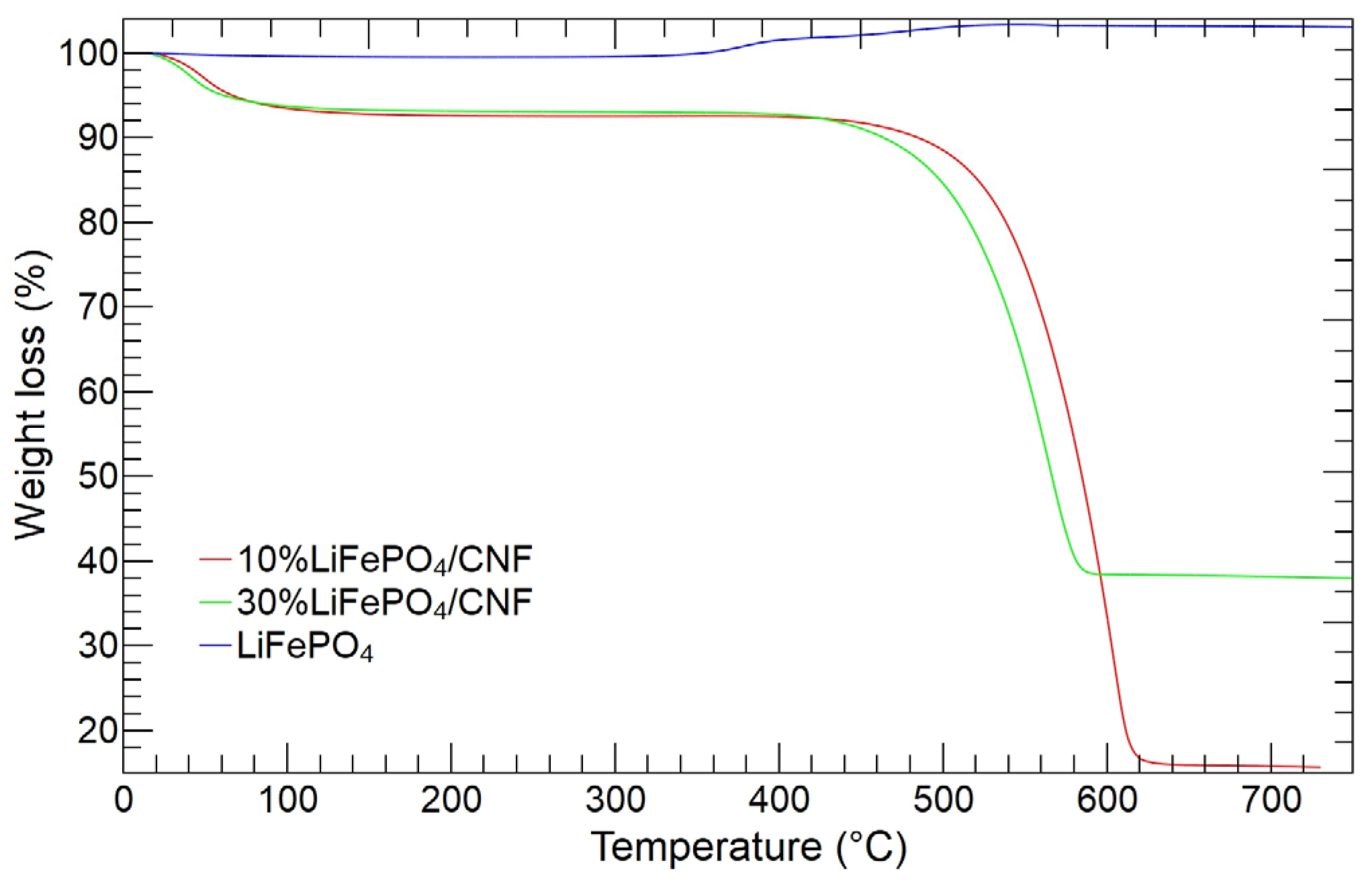
3.1. LiFePO4 and LiFePO4/CNF Characterization

In Figure 2, the X-ray diffraction patterns of the pure CNFs, LiFePO4, 10%LiFePO4/CNF, and 30%LiFePO4/CNF samples are shown. The peaks of the LiFePO4 powder compare well to those deposited in the JCPDS database (PDF# 40-1499) and pertain to the orthorhombic olivine-type crystal structure with the Pnma space group (a = 10.3268(1) Å, b = 5.9975 Å, c = 4.6945 Å) [62]. The pure CNF sample displays a broad band at about 25°, distinctive of the amorphous phases. In the LiFePO4/CNF samples, both the amorphous component and the crystalline olivine-type structure are detected. The amorphous band is less pronounced in the 30%LiFePO4/CNF sample, which contains a higher amount of active material. As expected, the LiFePO4 powder is successfully loaded into carbon nanofibers by electrospinning. The Rietveld refinement of the diffraction data is carried out on the LiFePO4 and LiFePO4/CNF samples, based on the structural model reported in [62]. The refined lattice parameters, cell volume, and discrepancy factors are reported in Table S1, and the calculated and experimental patterns are shown in Figure S1. The refined model properly fits the experimental diffraction data. The LiFePO4 lattice parameters and cell volume of the LiFePO4/CNF samples are well compared to the pure LiFePO4 ones. The carbonization process at 750 °C in N2 does not affect the olivine-type crystal structure.
The Raman spectroscopy aimed to further assess the crystalline quality of the different samples and to evaluate the carbon coating. In Figure 3, the Raman spectra from 10%LiFePO4/CNF and 30%LiFePO4/CNF samples are shown in the range of 200–1800 cm−1 together with that from CNF sample, reported for comparison. In the inset, the Raman spectrum from commercial LiFePO4 powder is reported as well.
For the LiFePO4 sample, we obtain a Raman spectrum perfectly consistent with the expected Raman yield of the olivine structure. The main Raman band at 950 cm−1 is due to the ν1 intramolecular stretching mode of the PO43− unit. Close to this mode, at slightly higher energies, ν2 and ν3 modes due to symmetric and asymmetric P–O bonds vibrations are detectable [63,64].
Between 400 and 700 cm−1, other Raman features are detectable. The weak and broadened features prevent a clear assignment, but at these energies, bending modes of PO43− are active together with PO43− deformation modes. Below 400 cm−1 the Raman signals are due to the external modes of the olivine structure, composed mainly of whole-body translatory and vibrational motions of the PO43− ions and translatory motion of the Fe2+ ions. All these features clearly indicate a well-ordered olivine structure. When the Raman spectrum is collected from carbon-coated samples, a different behavior is observed. The signal from LiFePO4 is completely overwhelmed by the intense carbon-related Raman features, with two broadened bands peaking approximately at around 1350 and 1590 cm−1 due to sp3-type amorphous carbonaceous material (D-mode) and to the sp2 graphite-like (G band). The absence of an olivine Raman signal is not surprising, because the different Raman cross-sections and the CNFs present in the samples prevent the excitation of the inner olivine structure.
It is interesting to compare the carbon crystal qualities of different samples looking at the intensities of G and D modes. Indeed, it is well known that the integrated intensity ratio between G and D bands is a parameter of choice to verify the quality of carbon materials [65]. In this case, the ratio IG/ID for 10%LiFePO4/CNF and 30%LiFePO4/CNF is equal to 0.71 and 0.68, respectively. These values are very similar to that obtained from CNF samples (IG/ID = 0.67).
Figure 4 displays the SEM and TEM images of the LiFePO4 powder. The SEM image (Figure 4a) shows aggregates of a micrometric size composed of nanometric particles. The agglomerates’ surface is irregular but defined, and the sub-particles display a homogeneous morphology. The TEM micrograph (Figure 4b) confirms the presence of aggregates of rounded nanoparticles (see also Figure S2 in Supplementary Information) with diameters ranging between 13 and 155 nm.
Figure 5 shows the surface and cross-section SEM images of the self-standing cathodes. The 10%LiFePO4/CNF sample (Figure 5a–c) consists of LiFePO4 micrometric agglomerates dispersed between and into the CNFs. The CNFs have diameters of about 250 nm, and the sheet thickness is about 200 µm. Figure 5d–f show the SEM images of the surface and cross-section of the 30%LiFePO4/CNF sample. As for the 10%LiFePO4/CNF self-standing electrode, LiFePO4 agglomerates greater than 1 µm are spread into CNFs with a diameter of about 80 nm. In this sample, the agglomerates of active material embedded into the CNF diameter are more evident. The sheet thickness is about 180 µm.
Figure 6 shows the TEM images of the self-standing samples. The TEM investigation confirms the SEM results: in both the 10%LiFePO4/CNF (Figure 6a,b) and 30%LiFePO4/CNF (Figure 6c,d) samples, the LiFePO4 agglomerates are present between and within the nanofibers. For the 10%LiFePO4/CNF electrode, the agglomerates are formed by sub-particles with nanometric sizes ranging between 45 and 72 nm. The CNFs display variable diameters in the 90–250 nm range. In the case of the 30%LiFePO4/CNF sample, the agglomerates are larger and connect nanofibers. The CNF diameter ranges between 200 and 330 nm.
The EDS analysis is applied to evaluate the LiFePO4 powder distribution on the surface (Figure 7) and within the cross-section (Figure 8) of the LiFePO4/CNF self-standing electrodes. In both samples, the Fe and P distribution maps confirm that the agglomerates detected between and within the CNFs are LiFePO4 and the particles are homogeneously distributed along the sheet thickness. This is beneficial for achieving good electrochemical performance, and it is difficult to be obtained by dip- and drop-coating. From the EDS elemental analysis, the atomic percentage of Fe and P is evaluated: we obtain a Fe:P mole ratio of 0.60:0.69 and 1.41:1.49 for the 10%LiFePO4/CNF and 30%LiFePO4/CNF samples, respectively. This result is consistent with the compound stoichiometry.
The thermogravimetric analysis is carried out to evaluate the weight percentage of LiFePO4 loaded within the carbon nanofiber sheets, to be compared to the amount used for the self-standing electrode synthesis (10 and 30 wt%).
The thermogravimetric curves of 10%LiFePO4/CNF, 30%LiFePO4/CNF, and LiFePO4 samples are shown in Figure 9. The TG curve of the LiFePO4 sample compares well to the literature data [66,67,68]. A small mass loss is detected below 200 °C, attributed to adsorbed water release, and then a mass gain occurs in the 350–600 °C temperature range, and the final mass value of 103.4 wt% is reached. The mass increase is attributed to the LiFePO4 oxidation in air to form Li3Fe2(PO4)3 and Fe2O3 [66,67,68]. In the case of the LiFePO4/CNF samples, a mass loss due to adsorbed water release occurs below 200 °C, followed by a relevant mass loss in the 400–650 °C temperature range. The latter mass change is attributed to the simultaneous occurrence of two thermal events: (i) the oxidation of the carbon component with CO2 release (mass loss) and (ii) LiFePO4 oxidation (mass uptake) [68]. The carbon amount in the self-standing cathodes can be calculated as the difference between the final masses of the LiFePO4 powder (103.4 wt%) and the LiFePO4/CNF samples (37.9 and 15.7 wt% for the 30%LiFePO4/CNF and 10%LiFePO4/CNF samples, respectively), and then the active material amount can be evaluated. The LiFePO4 content in the 10%LiFePO4/CNF and 30%LiFePO4/CNF samples is 12.3 and 34.5 wt%, respectively, and compares well to the synthesis values.

3.2. LiFePO4 and LiFePO4/CNF Electrochemical Characterization

The LiFePO4 exhibits one well-known red-ox peak caused by the reduction and oxidation of the Fe (II)/Fe (III) pair. The red-ox reactions are the following [69]:
O x i d a t i o n :   x L i F e P O 4 x F e P O 4 + x L i + + x e ,
R e d u c t i o n :   F e P O 4 + x L i + + x e x L i F e P O 4 + 1 x F e P O 4 .
Iron is the transition metal ion donating or accepting electrons. When the Fe (II) is oxidized to Fe (III), the lithium ions are extracted, while the reduction of Fe (III) to Fe (II) leads to the insertion of metal alkali ions. The mechanism of Li insertion has been extensively investigated [70].

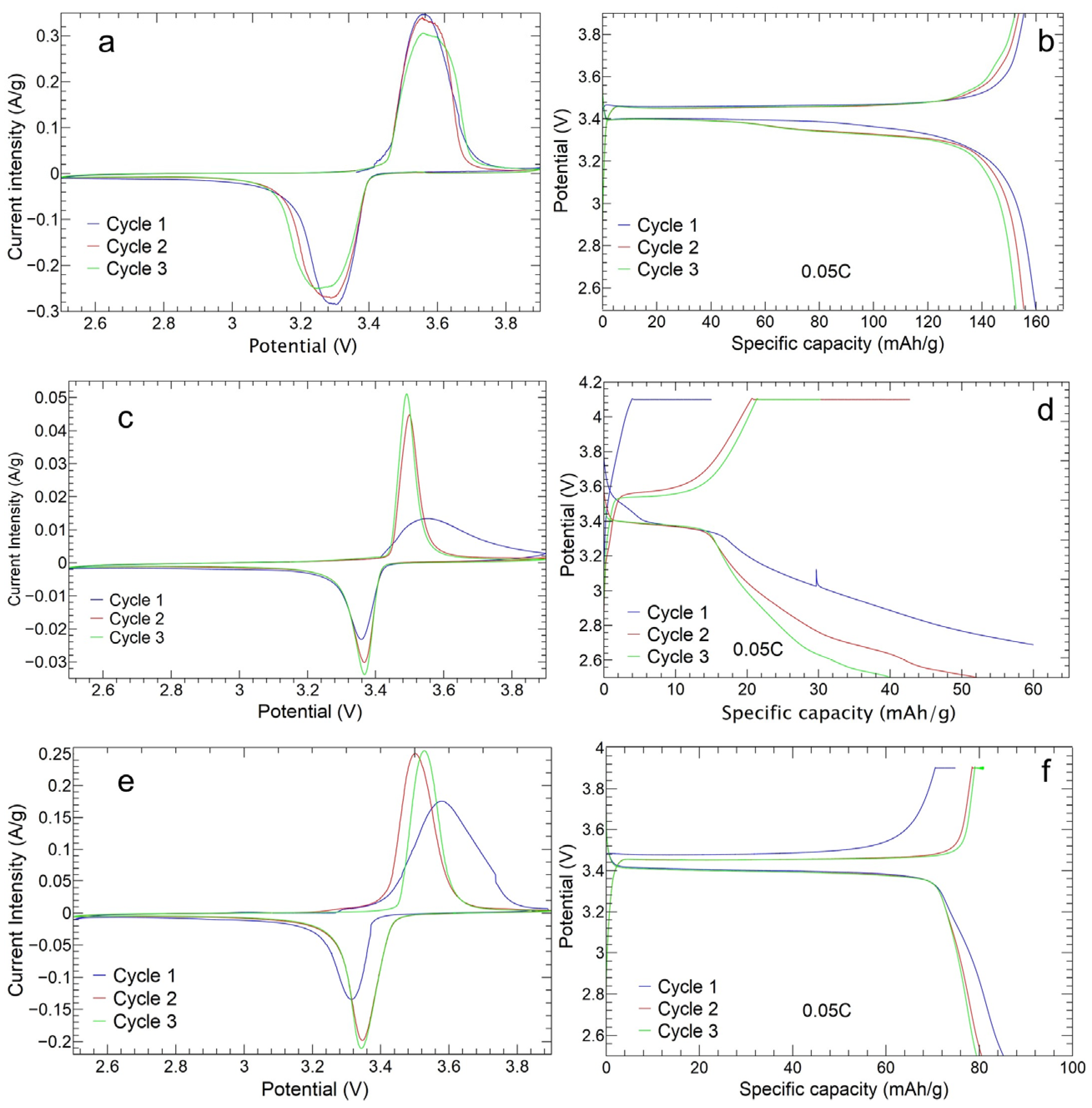
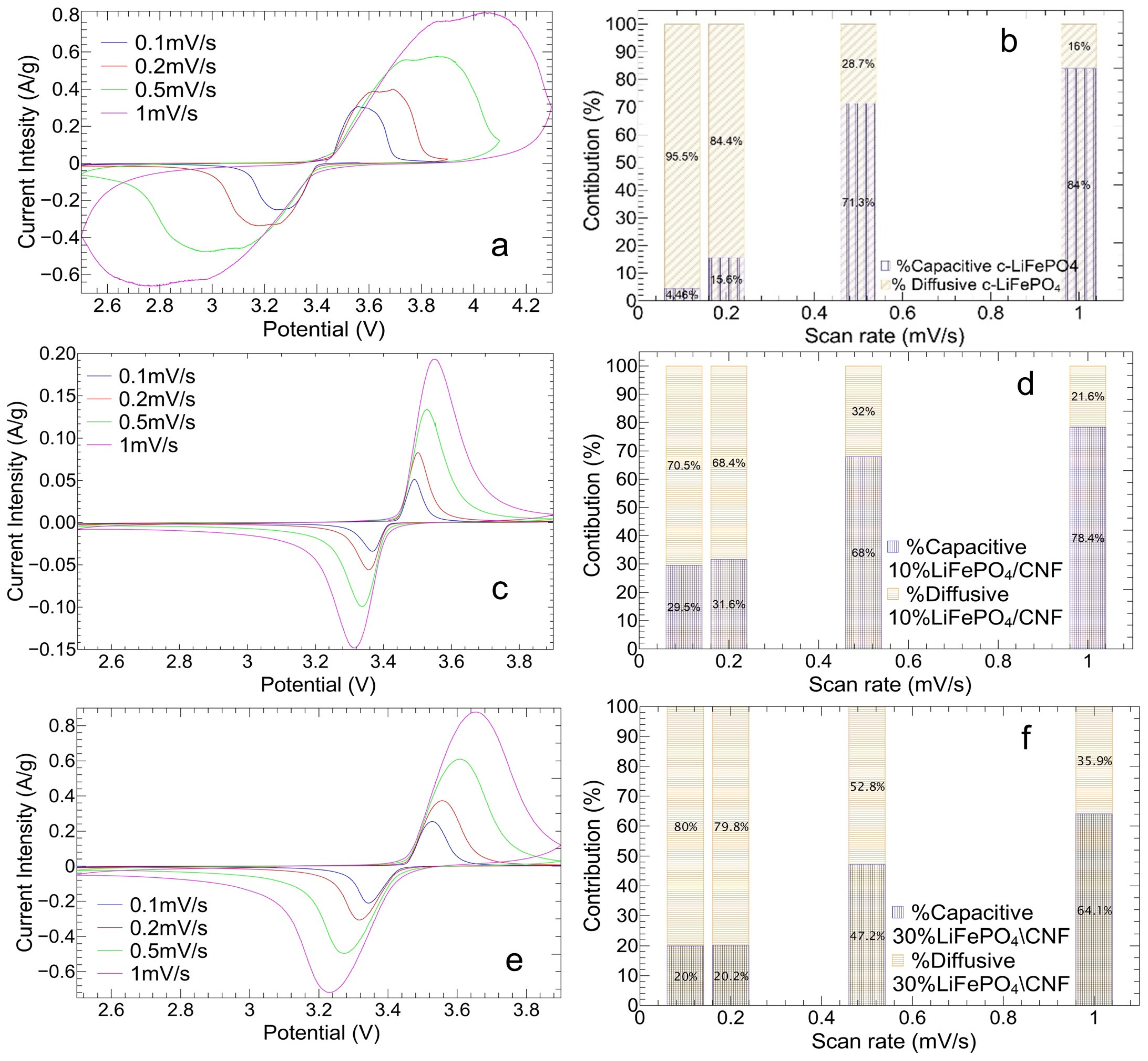
3.2.1. Cyclic Voltammetry Analysis

The CV curves and charge/discharge profiles of the first three cycles at 0.05C of the LiFePO4, 10%LiFePO4/CNF, and 30%LiFePO4/CNF samples are shown in Figure 10. The anodic/cathodic peaks of the Fe (II)/Fe (III) red-ox pair are detected at 3.56/3.29 V, 3.50/3.37 V, and 3.50/3.35 V, respectively, and these peaks correspond to the respective voltage plateaus in their charge/discharge profiles. In the case of the LiFePO4 tape-cast electrode, the CV curves and the charge/discharge profiles are quite overlapped, confirming a good electrochemical reversibility. The anodic/cathodic peak intensity current is 0.35/−0.27 A/g, and the ΔV is 270 mV, indicating a relevant polarization phenomenon. For 10%LiFePO4/CNF and 30%LiFePO4/CNF self-standing samples, the peak’s current intensity increases as the cycles increase, indicating a progressive activation of active particles available for Li ions’ insertion/extraction, as reported in the literature [48]. This is confirmed by the charge/discharge curves, too. The current intensities for the two samples are 0.045/−0.030 A/g and 0.24/−0.20 A/g, respectively; the values are lower than for the tape-casted electrode, according to the lower active material amount (12.3 and 34.5 wt%) present in the self-standing electrodes. For both samples, the ΔV is in the 130–150 mV range and lower than the tape-casted one, underling a smaller overpotential and polarization phenomenon for self-standing electrodes.
Figure 11a,c,e display the cyclic voltammetry of tape-casted and self-standing electrodes at different scan rates: 0.1 mV/s. 0.2 mV/s, 0.5 mV/s, and 1 mV/s. Figure 11b,d,f show the capacitive and diffusive contributions at each scan rate for the three samples. The data are analyzed to calculate the lithium-ion diffusion coefficient and the alkali metal-ion faradaic contribution (diffusion control) and non-faradaic one (pseudo-capacitance control) due to the creation of the double layer on the material surface. The relation between redox current ip (A) and scan rate ν (mV/s) reads as the following:
i p = k 1 ν + k 2 ν
where ν is the scan rate, ip is the peak current, while k1 and k2 are adjustable parameters [71]. The diffusion contribution is controlled by the square root term, thanks to the evaluation of the ip by the Randles–Sevick equation:
i p = 2.69 × 10 5 n 3 2 A C D ν
with n number of transferred electrons, A area, C Li+ concentration, and D diffusion coefficient. The quantities are given in the CGS unit system and at standard conditions. Using Equations (3) and (4), the diffusion coefficient D is calculated by evaluating the k2 term for the three samples.
The tape-casted LiFePO4 electrode (A = 0.78 cm2) exhibits diffusion coefficients for anodic and cathodic peaks of 4.66 × 10⁻¹² cm2/s and 3.34 × 10⁻¹² cm2/s, respectively, which compare to those in the literature [71]. The same analysis can be carried out for the 10%LiFePO4/CNF and 30%LiFePO4/CNF cathodes as well. The free-standing electrodes should benefit from the 3D structure, suitable for increasing the active material surface. Indeed, the effective areas A cannot be easily estimated, and we calculate an equivalent cathodic and anodic diffusion coefficient by using the area of the electrode section, as already done in the literature with other self-standing electrodes [72]. For 10%LiFePO4/CNF, the anodic diffusion coefficient is 5.08 × 10⁻¹⁴ cm2/s, while the cathodic one is 1.82 × 10⁻¹⁴ cm2/s. The result is congruent with the low amount of the active material, as the Fe (II)/Fe (III) redox pair has a lower current intensity than the tape-casted counterpart (see Figure 11a,c). Instead, the anodic and cathodic diffusion coefficients of the 30%LiFePO4/CNF cathode are 1.98 × 10⁻¹¹ cm2/s and 1.36 × 10⁻¹¹ cm2/s, respectively, consistent with the value found in the literature [73]. Enhanced D values of about four times are obtained compared to the tape-casted electrode. The result is also aligned with the values of current intensity (Figure 11a,e). The advantage of a higher active surface, which is reached with 30 wt% of the active material powder added to the CNF self-standing structure, compared to the 80% of the tape-casted electrode, is envisaged.
Figure 11b,d,f compare the diffusion and reaction (capacitive contribution) control at different CV sweep rates of the tape-casted and free-standing cathodes. The 10%LiFePO4/CNF and 30%LiFePO4/CNF samples show enhanced diffusion contributions at high scan rate values compared to the tape-casted counterpart, as expected in the presence of the very porous CNF sheets. Indeed, the non-woven nanofibers provide an easy electrolyte diffusion, which promotes contact with the active material [74]. It is also qualitatively confirmed by the contact angle analysis, dropping 5 µL of the electrolyte on the electrode surface (Figure S3). The electrolyte completely permeates the electrode within 50 ms, contrary to the slurry electrode, which shows a contact angle in the range of 32°–45°, as reported in the literature by Wang and coworkers [75]. Moreover, the 30%LiFePO4/CNF shows a diffusion control gain of about 18% at the highest scan rate (1 mV/s) with respect to the slurry, confirming the results of the coefficient diffusion. Notably, for all electrodes, the anodic and cathodic peaks clearly move toward right and left, respectively, as the scan rate increases, but this trend is lowered for self-standing cathodes (Figure 11a,c,e): the Fe (II)/Fe (III) redox peak overpotentials of the LiFePO4 sample are 303 mV, 486 mV, 774 mV, and 1237 mV as the scan rate increases, against 124 mV, 143 mV, 189 mV, and 236 mV for the 10%LiFePO4/CNF, and 185 mV, 239 mV, 335 mV, and 422 mV for the 30%LiFePO4/CNF, and this implies more reversible redox processes in the free-standing cathodes than in the tape-casted one.
The relationship of the normalized peak current as a function of the square root of the scan rate is also examined. The plot is shown in Figure S4 (Supplementary Information). The obtained linear trend confirms some increase in the ip for the 30%LiFePO4/CNF cathode compared to the tape-casted one for scan rates higher than 0.2 mV/s, according to the enhanced diffusion control. Lower values are instead obtained for the self-standing cathode, containing only the 12.3 wt% of active material. The electrochemical impedance spectroscopy (EIS) analysis is performed on the cycled cathodes, and the Nyquist plot and the equivalent circuit are shown in Figure S5 (Supplementary Information). The improved electrochemical performance of the 30%LiFePO4/CNF cathode is confirmed by the smaller charge-transfer resistance (147.15 Ω vs. 232.70 Ω and 239.94 Ω for the 12.3 wt% self-standing and the tape-casted electrodes) and faster charge-transfer at the electrode–electrolyte interface. The obtained charge-transfer resistances fairly compared to those in the literature [58]. The larger slope of Warburg impedance for the 30%LiFePO4/CNF cathode suggests a more favorable Li-ion transport in this self-standing electrode.

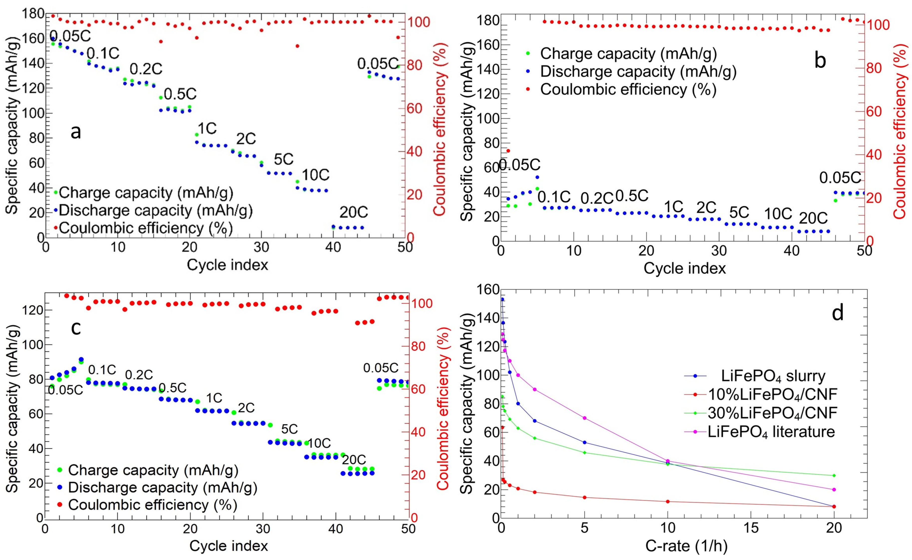
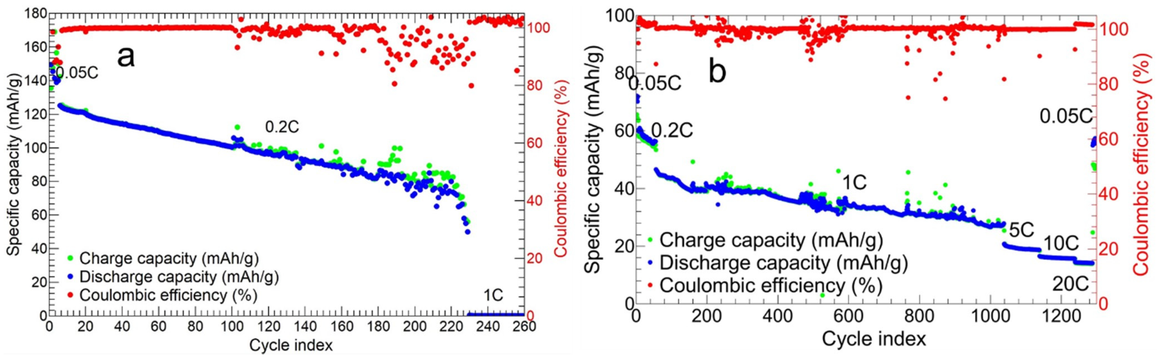
3.2.2. Charge and Discharge Cycles

The charge/discharge data for LiFePO4, 10%LiFePO4/CNF, and 30%LiFePO4/CNF samples are shown in Figure 12. The tape-cast cathode (Figure 12a) gives initial charge and discharge capacities of 155.48 and 159.84 mAh/g, respectively. The average discharge capacities are 153.07 mAh/g at 0.05C, 136.62 mAh/g at 0.1C, 123.40 mAh/g at 0.2C, 102.05 mAh/g at 0.5C, 80.10 mAh/g at 1C, 68.04 mAh/g at 2C, 52.95 mAh/g at 5C, 38.56 mAh/g at 10C, and 8.21 mAh/g at 20C. A capacity retention of 80% and coulombic efficiency ≥99% are obtained at the end of the measurement.
The 10%LiFePO4/CNF (Figure 12b) exhibits an initial charge and discharge capacity of 48.20 and 77.99 mAh/g, respectively. The average discharge capacities of 48.17, 27.34, 25.27, 22.88, 20.36, 17.87, 13.97, 11.20, and 7.96 mAh/g at 0.05C, 0.1C, 0.2C, 0.5C, 1C, 2C, 5C, 10C, and 20C, respectively, are obtained. The initial capacity is fully recovered with a coulombic efficiency of ≥99% at the end of the measurements. Differently from the LiFePO4 cathode, the self-standing 10%LiFePO4/CNF one demonstrates increased capacity in the first five cycles at 0.05C, confirming the availability of progressively activated particles for lithiation/delithiation, as suggested by CV analysis (Figure 10c) and reported by Bachtin and coworkers [48].
The 30%LiFePO4/CNF shows an initial charge capacity of 74.90 mAh/g and a discharge capacity of 81.80 mAh/g at 0.05C (Figure 12c). The average discharge capacities at 0.05C, 0.1C, 0.2C, 0.5C, 1C, 2C, 5C, 10C, and 20C are 85.15, 77.81, 74.52, 68.14, 61.68, 54.44, 43.11, 34.94, and 25.58 mAh/g, respectively. The capacity retention is 96.99%, and the coulombic efficiency is ≥98%; the capacity retention is consistent with other CNF-based composites for LIB cathodes [36]. As for the 10%LiFePO4/CNF sample, the 30%LiFePO4/CNF cathode shows an increasing value of capacity in the first five cycles at 0.05C (see also Figure 10e,f).
Figure 12d plots the average discharge capacities vs. C-rate for the three investigated cathodes. It demonstrates that the LiFePO4 tape-casted electrode exhibits higher capacity values below 5C. The capacity is comparable at 20C for the 10%LiFePO4/CNF and at 10C for the 30%LiFePO4/CNF cathode. While the literature, slurry data taken from [76] are even higher than other samples, but not at 20C, where the 30%LiFePO4/CNF self-standing electrode gives the best performance. Moreover, the 30%LiFePO4/CNF shows a slower capacity loss than other samples by changing the C-rate. These improved performances are also confirmed by the higher diffusion coefficient evaluated by the CV analysis at different scan rates. To conclude, the 30%LiFePO4/CNF exhibits (i) a slower capacity fading, increasing the C-rate, (ii) good reversibility and stability of lithium storage, and (iii) promising performances also at C-rates higher than 5C. The 30%LiFePO4/CNF’s good cycling at high C-rates is due to the CNF 3D porous network, which guarantees an easier diffusion of Li-ions. The consequence is a high-power density, as also reported in the literature [74]. Compared with the self-standing LiFePO4 cathode at 40% of active material in the literature [48], with a specific capacity of about 10 mAh/g at 1C, we show at the same C-rate a greater average value of 20.36 mAh/g for 10%LiFePO4/CNF and 61.68 mAh/g for 30%LiFePO4/CNF. Moreover, considering the study of Bachtin and coworkers [47], we can compare similar self-standing electrodes with the commercial powder of LiFePO4. Their capacity values at 1C compare fairly to ours, for non-chemically activated electrodes [47]. In the case of the 10%LiFePO4/CNF sample, the poorer electrochemical performances than the 30%LiFePO4/CNF depends on the very low amount of active material. Based on this, we carried out the long-term cycling only on the 30%LiFePO4/CNF and the LiFePO4 cathodes.
In Figure 13a, the long cycling of LiFePO4 tape-casted electrode is shown. It is cycled for five cycles at 0.05C, two hundred cycles at 0.2C, and finally fifty cycles at 1C. The average coulombic efficiency is ≥97%, and the initial discharge/charge capacities are equal to 145.4/147.6 mAh/g. The specific capacity progressively decreases, increasing the cycle index, and reaches negligible values at the 230th cycle at 1C. The long charge/discharge cycling for the 30%LiFePO4/CNF is shown in Figure 13b. The cathode is tested at 0.05C, 0.2C, 1C, 5C, 10C, and 20C for 5, 50, 1000, 100, 100, and 50 cycles, respectively. The initial charge and discharge capacities are 71.3 and 77.3 mAh/g, and the average coulombic efficiency is ≥98%. Even though the initial capacity is lower than the tape-casted electrode, the self-standing cathode exhibits a slower capacity loss and demonstrates electrochemical activity at C-rates higher than 0.2C, too. The average value of discharge capacities at 1C, 5C, 10C, and 20C are 35.2 mAh/g, 22.0 mAh/g, 16.9 mAh/g, and 14.9 mAh/g, and the value of 57.4 mAh/g is obtained for further cycling (10 cycles) at 0.05C. The capacity retention at the end of the measurement is 74.3% and is comparable to other lithium transition metal phosphates [41], while it is 35.4% at the end of the 1000 cycles at 1C. This is a good long cycling result, if compared to the LiFePO4 self-standing cathode reported in the literature [48], where capacity values of 30–40 mAh/g are obtained for over 200 cycles at 0.5C: the cell is tested for 750 cycles at 0.05C, 0.1C, 0.2C, and 0.5C. In our work, similar capacity values are obtained at 1C for over 1000 cycles, and the electrode can be further cycled at higher C-rates up to 20C. We can conclude that the self-standing electrode with only 34.53 wt% of active material shows a longer lifespan than the tape-casted one. This is due to the CNFs’ support, which limits the volume and structural changes of the active material and guarantees a good permeation of the electrolyte and a higher electronic conductivity.

4. Conclusions

In this study, we synthesize binder-free LiFePO4/CNF cathodes with lower active material amounts than that used in conventional cathodes. The self-standing electrodes are obtained by electrospinning, a simple and viable technique; the active material (commercial LiFePO4) is dispersed in the polymeric solution to be electrospun. The obtained membrane is stabilized and carbonized at 750 °C in a N2 flow. The thermal treatments do not alter the olivine-type crystal structure of LiFePO4, and the active material is homogeneously dispersed into and within nanofibers. Compared to the tape-casted cathode (80 wt% of LiFePO4), the low active material amount (10 and 30 wt%) implies the lowering of the anodic/cathodic peak current intensity and of the charge/discharge capacity values at low C-rates, but, notably, the CNF matrix allows for easier electrolyte diffusion and contact with LiFePO4 particles, beneficial for obtaining (i) higher Li+ diffusion coefficients, (ii) a reduction in polarization effects, and (iii) improved reversibility at high C-rates. In the case of the 30%LiFePO4/CNF sample, improved cycling performance and charge/discharge capacity values are obtained at high C-rates by using only the 34.5 wt% of active material.
The obtained results suggest that the applied synthetic strategy is suitable for preparing self-standing cathodes with appealing electrochemical performances at high C-rates by loading the active material in lower amounts than the traditional tape-casted cathodes.

Supplementary Materials

The following supporting information can be downloaded at https://www.mdpi.com/article/10.3390/electrochem5020014/s1, Figure S1: Rietveld refinement of the X-ray diffraction data of the LiFePO4 and LiFePO4/CNF samples; Figure S2: TEM images of the LiFePO4 nanoparticles; Figure S3: Electrolyte permeation in LiFePO4/CNF samples; Figure S4: Plot of the normalized peak current as a function of the scan rate for the LiFePO4, 10%LiFePO4/CNF, and 30%LiFePO4/CNF cathodes; Figure S5: Nyquist plot of the 30%LiFePO4/CNF, 10%LiFePO4/CNF, and LiFePO4 cathodes. Table S1: Lattice parameters, cell volume, and discrepancy factors obtained by the Rietveld refinement of the diffraction data of the LiFePO4 and LiFePO4/CNF samples.

Author Contributions

Conceptualization, D.C. and D.M.C.; formal analysis, D.C., D.M.C. and P.G.; investigation, D.M.C., C.U., B.A., V.B. and G.B.; resources, D.C.; supervision, D.C.; writing—original draft preparation, D.C., D.M.C. and P.G.; writing—review and editing, D.C., D.M.C., P.G. and C.U.; visualization, D.M.C., C.U. and B.A. All authors have read and agreed to the published version of the manuscript.

Funding

This research received no external funding.

Institutional Review Board Statement

Not applicable.

Informed Consent Statement

Not applicable.

Data Availability Statement

The data presented in this study are available on request from the corresponding author.

Acknowledgments

The authors are grateful to Massimo Boiocchi for the support in the TEM analysis performed at the Centro Grandi Strumenti, University of Pavia, and to Matteo Lugli of the Department of Physics at the University of Pavia for the creation of a handmade humidity control for the electrospinning process. The authors acknowledge support from the Ministero dell’Università e della Ricerca (MUR) and the University of Pavia through the program “Dipartimenti di Eccellenza 2023–2027”.

Conflicts of Interest

The authors declare no conflicts of interest.

References

  1. Oskouei, M.Z.; Şeker, A.A.; Tunçel, S.; Demirbaş, E.; Gözel, T.; Hocaoğlu, M.H.; Abapour, M.; Mohammadi-Ivatloo, B. A Critical Review on the Impacts of Energy Storage Systems and Demand-Side Management Strategies in the Economic Operation of Renewable-Based Distribution Network. Sustainability 2022, 14, 2110. [Google Scholar] [CrossRef]
  2. Dunn, B.; Kamath, H.; Tarascon, J.-M. Electrical Energy Storage for the Grid: A Battery of Choices. Science 2011, 334, 928–935. [Google Scholar] [CrossRef]
  3. Wang, B.; Li, X.; Zhang, X.; Luo, B.; Zhang, Y.; Zhi, L. Contact-Engineered and Void-Involved Silicon/Carbon Nanohybrids as Lithium-Ion-Battery Anodes. Adv. Mater. 2013, 25, 3560–3565. [Google Scholar] [CrossRef]
  4. Chen, L.; Yan, B.; Xu, J.; Wang, C.; Chao, Y.; Jiang, X.; Yang, G. Bicontinuous Structure of Li3V2(PO4)3 Clustered via Carbon Nanofiber as High-Performance Cathode Material of Li-Ion Batteries. ACS Appl. Mater. Interfaces 2015, 7, 13934–13943. [Google Scholar] [CrossRef]
  5. Gholami, T.; Salavati-Niasari, M.; Varshoy, S. Electrochemical Hydrogen Storage Capacity and Optical Properties of NiAl2O4/NiO Nanocomposite Synthesized by Green Method. Int. J. Hydrogen Energy 2017, 42, 5235–5245. [Google Scholar] [CrossRef]
  6. Zhou, L.; Zhang, K.; Hu, Z.; Tao, Z.; Mai, L.; Kang, Y.-M.; Chou, S.-L.; Chen, J. Recent Developments on and Prospects for Electrode Materials with Hierarchical Structures for Lithium-Ion Batteries. Adv. Energy Mater. 2018, 8, 1701415. [Google Scholar] [CrossRef]
  7. Eftekhari, A. Lithium Batteries for Electric Vehicles: From Economy to Research Strategy. ACS Sustain. Chem. Eng. 2019, 7, 5602–5613. [Google Scholar] [CrossRef]
  8. Duan, J.; Tang, X.; Dai, H.; Yang, Y.; Wu, W.; Wei, X.; Huang, Y. Building Safe Lithium-Ion Batteries for Electric Vehicles: A Review. Electrochem. Energy Rev. 2020, 3, 1–42. [Google Scholar] [CrossRef]
  9. Wang, J.; Chen, L.; Zeng, L.; Wei, Q.; Wei, M. In Situ Synthesis of WSe2/CMK-5 Nanocomposite for Rechargeable Lithium-Ion Batteries with a Long-Term Cycling Stability. ACS Sustain. Chem. Eng. 2018, 6, 4688–4694. [Google Scholar] [CrossRef]
  10. Sun, J.; Lian, G.; Jing, L.; Wu, D.; Cui, D.; Wang, Q.; Yu, H.; Zhang, H.; Wong, C.-P. Assembly of Flower-like VS2/N-Doped Porous Carbon with Expanded (001) Plane on rGO for Superior Na-Ion and K-Ion Storage. Nano Res. 2022, 15, 4108–4116. [Google Scholar] [CrossRef]
  11. Hou, Z.; Zhang, X.; Chen, J.; Qian, Y.; Chen, L.-F.; Lee, P.S. Towards High-Performance Aqueous Sodium Ion Batteries: Constructing Hollow NaTi2(PO4)3@C Nanocube Anode with Zn Metal-Induced Pre-Sodiation and Deep Eutectic Electrolyte. Adv. Energy Mater. 2022, 12, 2104053. [Google Scholar] [CrossRef]
  12. Liu, Y.-R.; Lei, Z.-W.; Liu, R.-P.; Li, X.-Y.; Xiong, P.-X.; Luo, Y.-J.; Chen, Q.-H.; Wei, M.-D.; Zeng, L.-X.; Qian, Q.-R. Sn-Doped Induced Stable 1T-WSe2 Nanosheets Entrenched on N-Doped Carbon with Extraordinary Half/Full Sodium/Potassium Storage Performance. Rare Met. 2023, 42, 1557–1569. [Google Scholar] [CrossRef]
  13. Kong, F.; Liang, C.; Longo, R.C.; Zheng, Y.; Cho, K. Atomic-Scale Understanding of Non-Stoichiometry Effects on the Electrochemical Performance of Ni-Rich Cathode Materials. J. Power Sources 2018, 378, 750–758. [Google Scholar] [CrossRef]
  14. Yasuhara, S.; Yasui, S.; Teranishi, T.; Chajima, K.; Yoshikawa, Y.; Majima, Y.; Taniyama, T.; Itoh, M. Enhancement of Ultrahigh Rate Chargeability by Interfacial Nanodot BaTiO3 Treatment on LiCoO2 Cathode Thin Film Batteries. Nano Lett. 2019, 19, 1688–1694. [Google Scholar] [CrossRef]
  15. Li, Y.; Wang, J.; Yao, J.; Huang, H.; Du, Z.; Gu, H.; Wang, Z. Enhanced Cathode Performance of LiFePO4/C Composite by Novel Reaction of Ethylene Glycol with Different Carboxylic Acids. Mater. Chem. Phys. 2019, 224, 293–300. [Google Scholar] [CrossRef]
  16. Pang, P.; Wang, Z.; Deng, Y.; Nan, J.; Xing, Z.; Li, H. Delayed Phase Transition and Improved Cycling/Thermal Stability by Spinel LiNi0.5Mn1.5O4 Modification for LiCoO2 Cathode at High Voltages. ACS Appl. Mater. Interfaces 2020, 12, 27339–27349. [Google Scholar] [CrossRef]
  17. Abou-Rjeily, J.; Bezza, I.; Laziz, N.A.; Autret-Lambert, C.; Sougrati, M.T.; Ghamouss, F. High-Rate Cyclability and Stability of LiMn2O4 Cathode Materials for Lithium-Ion Batteries from Low-Cost Natural β−MnO2. Energy Storage Mater. 2020, 26, 423–432. [Google Scholar] [CrossRef]
  18. Tabassam, R.; Alvi, F.; Aslam, N.; Raza, R.; Saifur-Rehman; Sherin, L.; Ajaml, M.; Ali, A. Electrochemical Investigation of LiMn2O4/Asphalt and LiMn2O4/Bituminous Coal Based Cathode Composites for Efficient Lithium-Ion Battery. Mater. Lett. 2021, 302, 130275. [Google Scholar] [CrossRef]
  19. Ha, Y.; Harvey, S.P.; Teeter, G.; Colclasure, A.M.; Trask, S.E.; Jansen, A.N.; Burrell, A.; Park, K. Long-Term Cyclability of Li4Ti5O12/LiMn2O4 Cells Using Carbonate-Based Electrolytes for behind-the-Meter Storage Applications. Energy Storage Mater. 2021, 38, 581–589. [Google Scholar] [CrossRef]
  20. Lin, J.; Sun, Y.-H.; Lin, X. Metal-Organic Framework-Derived LiFePO4 Cathode Encapsulated in O,F-Codoped Carbon Matrix towards Superior Lithium Storage. Nano Energy 2022, 91, 106655. [Google Scholar] [CrossRef]
  21. Armand, M.; Tarascon, J.-M. Building Better Batteries. Nature 2008, 451, 652–657. [Google Scholar] [CrossRef]
  22. Bruce, P.G.; Freunberger, S.A.; Hardwick, L.J.; Tarascon, J.-M. Li–O2 and Li–S Batteries with High Energy Storage. Nat. Mater. 2012, 11, 19–29. [Google Scholar] [CrossRef]
  23. Jo, C.-H.; Cho, D.-H.; Noh, H.-J.; Yashiro, H.; Sun, Y.-K.; Myung, S.T. An Effective Method to Reduce Residual Lithium Compounds on Ni-Rich Li[Ni0.6Co0.2Mn0.2]O2 Active Material Using a Phosphoric Acid Derived Li3PO4 Nanolayer. Nano Res. 2015, 8, 1464–1479. [Google Scholar] [CrossRef]
  24. Lu, J.; Tian, X.; Zhou, Y.; Zhu, Y.; Tang, Z.; Ma, B.; Wu, G.; Jiang, T.; Tu, X.; Chen, G.Z. A Novel “Holey-LFP/Graphene/Holey-LFP” Sandwich Nanostructure with Significantly Improved Rate Capability for Lithium Storage. Electrochim. Acta 2019, 320, 134566. [Google Scholar] [CrossRef]
  25. Cao, Z.; Sang, M.; Chen, S.; Jia, J.; Yang, M.; Zhang, H.; Li, X.; Yang, S. In Situ Constructed (010)-Oriented LiFePO4 Nanocrystals/Carbon Nanofiber Hybrid Network: Facile Synthesis of Free-Standing Cathodes for Lithium-Ion Batteries. Electrochim. Acta 2020, 333, 135538. [Google Scholar] [CrossRef]
  26. Adepoju, A.A.; Williams, Q.L. High C-Rate Performance of LiFePO4/Carbon Nanofibers Composite Cathode for Li-Ion Batteries. Curr. Appl. Phys. 2020, 20, 1–4. [Google Scholar] [CrossRef]
  27. Wang, B.; Wang, D.; Wang, Q.; Liu, T.; Guo, C.; Zhao, X. Improvement of the Electrochemical Performance of Carbon-Coated LiFePO4 Modified with Reduced Graphene Oxide. J. Mater. Chem. A 2012, 1, 135–144. [Google Scholar] [CrossRef]
  28. Yang, S.; Hu, M.; Xi, L.; Ma, R.; Dong, Y.; Chung, C.Y. Solvothermal Synthesis of Monodisperse LiFePO4 Micro Hollow Spheres as High Performance Cathode Material for Lithium Ion Batteries. ACS Appl. Mater. Interfaces 2013, 5, 8961–8967. [Google Scholar] [CrossRef]
  29. Ramasubramanian, B.; Sundarrajan, S.; Chellappan, V.; Reddy, M.V.; Ramakrishna, S.; Zaghib, K. Recent Development in Carbon-LiFePO4 Cathodes for Lithium-Ion Batteries: A Mini Review. Batteries 2022, 8, 133. [Google Scholar] [CrossRef]
  30. Johnson, I.D.; Lübke, M.; Wu, O.Y.; Makwana, N.M.; Smales, G.J.; Islam, H.U.; Dedigama, R.Y.; Gruar, R.I.; Tighe, C.J.; Scanlon, D.O.; et al. Pilot-Scale Continuous Synthesis of a Vanadium-Doped LiFePO4/C Nanocomposite High-Rate Cathodes for Lithium-Ion Batteries. J. Power Sources 2016, 302, 410–418. [Google Scholar] [CrossRef]
  31. Habedank, J.B.; Günter, F.J.; Billot, N.; Gilles, R.; Neuwirth, T.; Reinhart, G.; Zaeh, M.F. Rapid Electrolyte Wetting of Lithium-Ion Batteries Containing Laser Structured Electrodes: In Situ Visualization by Neutron Radiography. Int. J. Adv. Manuf. Technol. 2019, 102, 2769–2778. [Google Scholar] [CrossRef]
  32. Zhang, Q.; Zhou, J.; Zeng, G.; Ren, S. Effect of Lanthanum and Yttrium Doped LiFePO4 Cathodes on Electrochemical Performance of Lithium-Ion Battery. J. Mater. Sci. 2023, 58, 8463–8477. [Google Scholar] [CrossRef]
  33. Yang, S.; Zhou, X.; Zhang, J.; Liu, Z. Morphology-Controlled Solvothermal Synthesis of LiFePO4 as a Cathode Material for Lithium-Ion Batteries. J. Mater. Chem. 2010, 20, 8086–8091. [Google Scholar] [CrossRef]
  34. Shi, Y.; Chou, S.-L.; Wang, J.-Z.; Wexler, D.; Li, H.-J.; Liu, H.-K.; Wu, Y. Graphene Wrapped LiFePO4/C Composites as Cathode Materials for Li-Ion Batteries with Enhanced Rate Capability. J. Mater. Chem. 2012, 22, 16465–16470. [Google Scholar] [CrossRef]
  35. Li, W.; Li, M.; Adair, K.R.; Sun, X.; Yu, Y. Carbon Nanofiber-Based Nanostructures for Lithium-Ion and Sodium-Ion Batteries. J. Mater. Chem. A 2017, 5, 13882–13906. [Google Scholar] [CrossRef]
  36. Weng, W.; Kurihara, R.; Wang, J.; Shiratori, S. Electrospun Carbon Nanofiber-Based Composites for Lithium-Ion Batteries: Structure Optimization towards High Performance. Compos. Commun. 2019, 15, 135–148. [Google Scholar] [CrossRef]
  37. Ma, D.; Zhang, P.; Li, Y.; Ren, X. Li1.2Mn0.54Ni0.13Co0.13O2-Encapsulated Carbon Nanofiber Network Cathodes with Improved Stability and Rate Capability for Li-Ion Batteries. Sci. Rep. 2015, 5, 11257. [Google Scholar] [CrossRef]
  38. Yu, X.; Deng, J.; Yang, X.; Li, J.; Huang, Z.-H.; Li, B.; Kang, F. A Dual-Carbon-Anchoring Strategy to Fabricate Flexible LiMn2O4 Cathode for Advanced Lithium-Ion Batteries with High Areal Capacity. Nano Energy 2020, 67, 104256. [Google Scholar] [CrossRef]
  39. Dimesso, L.; Spanheimer, C.; Jaegermann, W.; Zhang, Y.; Yarin, A.L. LiFePO4—3D Carbon Nanofiber Composites as Cathode Materials for Li-Ions Batteries. J. Appl. Phys. 2012, 111, 064307. [Google Scholar] [CrossRef]
  40. von Hagen, R.; Lepcha, A.; Song, X.; Tyrra, W.; Mathur, S. Influence of Electrode Design on the Electrochemical Performance of Li3V2(PO4)3/C Nanocomposite Cathode in Lithium Ion Batteries. Nano Energy 2013, 2, 304–313. [Google Scholar] [CrossRef]
  41. Shin, J.; Yang, J.; Sergey, C.; Song, M.-S.; Kang, Y.-M. Carbon Nanofibers Heavy Laden with Li3V2(PO4)3 Particles Featuring Superb Kinetics for High-Power Lithium Ion Battery. Adv. Sci. 2017, 4, 1700128. [Google Scholar] [CrossRef]
  42. Choi, M.; Kim, H.-S.; Lee, Y.M.; Choi, W.-K.; Jin, B.-S. The High Electrochemical Performance of Li3V2(PO4)3 Supported by Graphene and Carbon-Nanofibers for Advanced Li-Ion Batteries. Mater. Res. Bull. 2016, 73, 211–218. [Google Scholar] [CrossRef]
  43. Zhang, S.; Lin, Z.; Ji, L.; Li, Y.; Xu, G.; Xue, L.; Li, S.; Lu, Y.; Toprakci, O.; Zhang, X. Cr-Doped Li2MnSiO4/Carbon Composite Nanofibers as High-Energy Cathodes for Li-Ion Batteries. J. Mater. Chem. 2012, 22, 14661–14666. [Google Scholar] [CrossRef]
  44. Park, H.; Song, T.; Tripathi, R.; Nazar, L.F.; Paik, U. Li2MnSiO4/Carbon Nanofiber Cathodes for Li-Ion Batteries. Ionics 2014, 20, 1351–1359. [Google Scholar] [CrossRef]
  45. Song, H.J.; Kim, J.-C.; Choi, M.; Choi, C.; Dar, M.A.; Lee, C.W.; Park, S.; Kim, D.-W. Li2MnSiO4 Nanorods-Embedded Carbon Nanofibers for Lithium-Ion Battery Electrodes. Electrochim. Acta 2015, 180, 756–762. [Google Scholar] [CrossRef]
  46. Zhu, C.; Mu, X.; van Aken, P.A.; Yu, Y.; Maier, J. Single-Layered Ultrasmall Nanoplates of MoS2 Embedded in Carbon Nanofibers with Excellent Electrochemical Performance for Lithium and Sodium Storage. Angew. Chem. Int. Ed. 2014, 53, 2152–2156. [Google Scholar] [CrossRef]
  47. Bachtin, K.; Kaus, M.; Pfaffmann, L.; Indris, S.; Knapp, M.; Roth, C.; Ehrenberg, H. Comparison of Electrospun and Conventional LiFePO4/C Composite Cathodes for Li-Ion Batteries. Mater. Sci. Eng. B 2016, 213, 98–104. [Google Scholar] [CrossRef]
  48. Bachtin, K.; Kramer, D.; Chakravadhanula, V.S.K.; Mu, X.; Trouillet, V.; Kaus, M.; Indris, S.; Ehrenberg, H.; Roth, C. Activation and Degradation of Electrospun LiFePO4 Battery Cathodes. J. Power Sources 2018, 396, 386–394. [Google Scholar] [CrossRef]
  49. Meligrana, G.; Ferrari, S.; Lucherini, L.; Celè, J.; Colò, F.; Brugger, J.; Ricciardi, C.; Ruffo, R.; Gerbaldi, C. Na3V2(PO4)3-Supported Electrospun Carbon Nanofiber Nonwoven Fabric as Self-Standing Na-Ion Cell Cathode. ChemElectroChem 2020, 7, 1652–1659. [Google Scholar] [CrossRef]
  50. Conti, D.M.; Fusaro, C.; Bruni, G.; Galinetto, P.; Albini, B.; Milanese, C.; Berbenni, V.; Capsoni, D. ZnS–rGO/CNF Free-Standing Anodes for SIBs: Improved Electrochemical Performance at High C-Rate. Nanomaterials 2023, 13, 1160. [Google Scholar] [CrossRef]
  51. Nishide, H.; Oyaizu, K. Toward Flexible Batteries. Science 2008, 319, 737–738. [Google Scholar] [CrossRef]
  52. Zeng, W.; Shu, L.; Li, Q.; Chen, S.; Wang, F.; Tao, X.-M. Fiber-Based Wearable Electronics: A Review of Materials, Fabrication, Devices, and Applications. Adv. Mater. 2014, 26, 5310–5336. [Google Scholar] [CrossRef]
  53. Liu, W.; Song, M.-S.; Kong, B.; Cui, Y. Flexible and Stretchable Energy Storage: Recent Advances and Future Perspectives. Adv. Mater. 2017, 29, 1603436. [Google Scholar] [CrossRef]
  54. Chang, J.; Huang, Q.; Gao, Y.; Zheng, Z. Pathways of Developing High-Energy-Density Flexible Lithium Batteries. Adv. Mater. 2021, 33, 2004419. [Google Scholar] [CrossRef]
  55. Zhang, F.; Qi, L. Recent Progress in Self-Supported Metal Oxide Nanoarray Electrodes for Advanced Lithium-Ion Batteries. Adv. Sci. 2016, 3, 1600049. [Google Scholar] [CrossRef]
  56. Lee, S.-H.; Jung, M.-J.; Im, J.S.; Sheem, K.-Y.; Lee, Y.-S. Preparation and Characterization of Electrospun LiFePO4/Carbon Complex Improving Rate Performance at High C-Rate. Res. Chem. Intermed. 2010, 36, 591–602. [Google Scholar] [CrossRef]
  57. Hu, Y.; Guo, P.; Thompson, J.; Wang, Z. Rational Design of Mesoporous LiFePO4@C Nanofibers as Cathode Materials for Energy Storage. Ceram. Int. 2017, 43, 10201–10206. [Google Scholar] [CrossRef]
  58. Zhang, C.; Yao, L.; Qiu, Y. Synthesis and Characterization of LiFePO4–Carbon Nanofiber–Carbon Nanotube Composites Prepared by Electrospinning and Thermal Treatment as a Cathode Material for Lithium-Ion Batteries. J. Appl. Polym. Sci. 2016, 133. [Google Scholar] [CrossRef]
  59. Liu, J.; Hu, X.; Ran, F.; Wang, K.; Dai, J.; Zhu, X. Electrospinning-Assisted Construction of 3D LiFePO4@rGO/Carbon Nanofibers as Flexible Cathode to Boost the Rate Capabilities of Lithium-Ion Batteries. Ceram. Int. 2023, 49, 1401–1408. [Google Scholar] [CrossRef]
  60. Zhang, W.; He, X.; Pu, W.; Li, J.; Wan, C. Effect of Slurry Preparation and Dispersion on Electrochemical Performances of LiFePO4 Composite Electrode. Ionics 2011, 17, 473–477. [Google Scholar] [CrossRef]
  61. Bruker AXS TOPAS V3.0: General Profile and Structural Analysis Software for Powder Diffraction Data. In User Manual Bruker AXS; Bruker AXS: Karlsruhe, Germany, 2005.
  62. Bini, M.; Ferrari, S.; Capsoni, D.; Mustarelli, P.; Spina, G.; Giallo, F.D.; Lantieri, M.; Leonelli, C.; Rizzuti, A.; Massarotti, V. Pair Distribution Function Analysis and Mössbauer Study of Defects in Microwave-Hydrothermal LiFePO4. RSC Adv. 2011, 2, 250–258. [Google Scholar] [CrossRef]
  63. Zaghib, K.; Mauger, A.; Goodenough, J.B.; Gendron, F.; Julien, C.M. Design and Properties of LiFePO4 Positive Electrode Materials for Li-Ion Batteries. In Advanced Materials and Methodes for Lithium-Ion Batteries; Zhang, S.S., Ed.; Transworld Research Network: Trivandrum, India, 2007; ISBN 978-81-7895-279-6. [Google Scholar]
  64. Kumar, A.; Thomas, R.; Karan, N.K.; Saavedra-Arias, J.J.; Singh, M.K.; Majumder, S.B.; Tomar, M.S.; Katiyar, R.S. Structural and Electrochemical Characterization of Pure LiFePO4 and C-LiFePO4 Nanocomposite C- Cathodes for Lithium Ion Rechargeable Batteries. J. Nanotechnol. 2009, 2009, 176517. [Google Scholar] [CrossRef]
  65. Ferrari, A.C.; Robertson, J. Interpretation of Raman Spectra of Disordered and Amorphous Carbon. Phys. Rev. B 2000, 61, 14095–14107. [Google Scholar] [CrossRef]
  66. Belharouak, I.; Johnson, C.; Amine, K. Synthesis and Electrochemical Analysis of Vapor-Deposited Carbon-Coated LiFePO4. Electrochem. Commun. 2005, 7, 983–988. [Google Scholar] [CrossRef]
  67. Hamelet, S.; Gibot, P.; Casas-Cabanas, M.; Bonnin, D.; Grey, C.P.; Cabana, J.; Leriche, J.-B.; Rodriguez-Carvajal, J.; Courty, M.; Levasseur, S.; et al. The Effects of Moderate Thermal Treatments under Air on LiFePO4-Based Nano Powders. J. Mater. Chem. 2009, 19, 3979–3991. [Google Scholar] [CrossRef]
  68. Delaporte, N.; Trudeau, M.L.; Bélanger, D.; Zaghib, K. Protection of LiFePO4 against Moisture. Materials 2020, 13, 942. [Google Scholar] [CrossRef]
  69. Padhi, A.K.; Nanjundaswamy, K.S.; Goodenough, J.B. Phospho-olivines as Positive-Electrode Materials for Rechargeable Lithium Batteries. J. Electrochem. Soc. 1997, 144, 1188–1194. [Google Scholar] [CrossRef]
  70. Malik, R.; Abdellahi, A.; Ceder, G. A Critical Review of the Li Insertion Mechanisms in LiFePO4 Electrodes. J. Electrochem. Soc. 2013, 160, A3179. [Google Scholar] [CrossRef]
  71. Yu, D.Y.W.; Donoue, K.; Inoue, T.; Fujimoto, M.; Fujitani, S. Effect of Electrode Parameters on LiFePO4 Cathodes. J. Electrochem. Soc. 2006, 153, A835. [Google Scholar] [CrossRef]
  72. Hu, Y.; Gu, D.; Jiang, H.; Wang, L.; Sun, H.; Wang, J.; Shen, L. Electrochemical Performance of LiFePO4/C via Coaxial and Uniaxial Electrospinning Method. Adv. Chem. Eng. Sci. 2016, 6, 149–157. [Google Scholar] [CrossRef]
  73. Chen, Q.; Qiao, X.; Peng, C.; Zhang, T.; Wang, Y.; Wang, X. Electrochemical Performance of Electrospun LiFePO4/C Submicrofibers Composite Cathode Material for Lithium Ion Batteries. Electrochim. Acta 2012, 78, 40–48. [Google Scholar] [CrossRef]
  74. Vu, A.; Qian, Y.; Stein, A. Porous Electrode Materials for Lithium-Ion Batteries—How to Prepare Them and What Makes Them Special. Adv. Energy Mater. 2012, 2, 1056–1085. [Google Scholar] [CrossRef]
  75. Wang, Y.; Zhang, J.; Xue, J.; Zhang, K.; Wen, L.; Liang, G. Effect of Particle Dispersion on the Properties of LiFePO4 Slurry and the Electrochemical Properties of the Battery. Ionics 2022, 28, 1547–1558. [Google Scholar] [CrossRef]
  76. Dominko, R.; Bele, M.; Gaberscek, M.; Remskar, M.; Hanzel, D.; Pejovnik, S.; Jamnik, J. Impact of the Carbon Coating Thickness on the Electrochemical Performance of LiFePO4/C Composites. J. Electrochem. Soc. 2005, 152, A607. [Google Scholar] [CrossRef]
Figure 1. Scheme of the synthetic approaches used for the electrodes’ preparation.
Electrochem 05 00014 g001
Figure 2. X-ray patterns of LiFePO4, 10%LiFePO4/CNF, 30%LiFePO4/CNF, and pure CNF carbonized at 750 °C.
Electrochem 05 00014 g002
Figure 3. Raman spectra of LiFePO4, 10%LiFePO4/CNF, 30%LiFePO4/CNF, and pure CNF, carbonized at 750 °C.
Electrochem 05 00014 g003
Figure 4. SEM ((a): 30kX) and TEM (b) images of LiFePO4.
Electrochem 05 00014 g004
Figure 5. SEM images of the surface ((a): 9kX, (b): 25kX) and cross-section ((c): 130X) of the 10%LiFePO4/CNF sample. SEM images of the surface ((d): 9kX, (e): 25kX) and cross-section ((f): 170X) of the 30%LiFePO4/CNF sample.
Electrochem 05 00014 g005
Figure 6. TEM images of the 10%LiFePO4/CNF (a,b) and 30%LiFePO4/CNF (c,d) samples.
Electrochem 05 00014 g006
Figure 7. EDS analysis. 10%LiFePO4/CNF sample: investigated surface (a) and Fe (b) and P (c) distribution maps; 30%LiFePO4/CNF sample: investigated surface (d) and Fe (e) and P (f) distribution maps.
Electrochem 05 00014 g007
Figure 8. EDS analysis. 10%LiFePO4/CNF sample: investigated cross-section (a) and Fe (b) and P (c) distribution maps; 30%LiFePO4/CNF sample: investigated cross-section (d) and Fe (e) and P (f) distribution maps. The white frame in (a) and (d) indicates the mapped portion.
Electrochem 05 00014 g008
Figure 9. TGA curves of 10%LiFePO4/CNF (red), 30%LiFePO4/CNF (green), and LiFePO4 (blue).
Electrochem 05 00014 g009
Figure 10. Cyclic voltammetry and charge/discharge curve of LiFePO4 (a,b), 10%LiFePO4/CNF (c,d), and 30%LiFePO4/CNF (e,f).
Electrochem 05 00014 g010
Figure 11. CV and capacitive/diffusive contributions at different scan rates of LiFePO4 (a,b), 10%LiFePO4/CNF (c,d), and 30%LiFePO4/CNF (e,f) samples.
Electrochem 05 00014 g011
Figure 12. Charge/discharge cycles at different C-rates of LiFePO4 (a), 10%LiFePO4/CNF (b), 30%LiFePO4/CNF (c), and comparisons of the electrochemical performance (d).
Electrochem 05 00014 g012
Figure 13. Long charge/discharge cycles of LiFePO4 tape-casted (a) and 30%LiFePO4/CNF self-standing (b) cathodes.
Electrochem 05 00014 g013
Disclaimer/Publisher’s Note: The statements, opinions and data contained in all publications are solely those of the individual author(s) and contributor(s) and not of MDPI and/or the editor(s). MDPI and/or the editor(s) disclaim responsibility for any injury to people or property resulting from any ideas, methods, instructions or products referred to in the content.

