Abstract
Understanding the operation of filters used to remove particulates from fluids is important in many practical industries. Typically the particles are larger than the pores in the filter so a cake layer of particles forms on the filter surface. Here we extend existing models for filter blocking to account for deformation of the filter material and the cake layer due to the applied pressure that drives the fluid. These deformations change the permeability of the filter and the cake and hence the flow. We develop a new theory of compressible-cake filtration based on a simple poroelastic model in which we assume that the permeability depends linearly on local deformation. This assumption allows us to derive an explicit filtration law. The model predicts the possible shutdown of the filter when the imposed pressure difference is sufficiently large to reduce the permeability at some point to zero. The theory is applied to industrially relevant operating conditions, namely constant flux, maximising flux and constant pressure drop. Under these conditions, further analytical results are obtained, which yield predictions for optimal filter design with respect to given properties of the filter materials and the particles.
1. Introduction
Membranes are an ideal choice for filtering of fluids because they can create highly selective barriers that can retain particles due to various processes such as size-exclusion (straining), electro-chemical and other effects [1]. As a result, membrane filtration has become the method of choice in various applications for separations, not only due to its economic advantage over other separation techniques due to lower energy costs, but also because it is better suited to preserve the quality of the product in the food and beverage industry than other purification processes [2]. Applications in industry range from small-scale (protein filtration, virus removal) to large-scale (wastewater treatment) processes. Classical modes of operation include dead-end and cross-flow filtration, depending on whether the filter membrane surface is, respectively, either perpendicular or parallel to the flow direction [3].
There are two main different ways in which the particles in the fluid can be retained by the membrane. In the first, which is characterised by the particles being small compared to the membrane pores, retention occurs inside the membrane, while in the second, which is characterised by the particles being bigger than the membrane pores, retention occurs by particles forming an additional layer on top of the membrane, usually referred to as a cake. In this work, we will refer to the whole device comprising a filter (the membrane) and a cake as a filtercake. Modelling of cake formation during both dead-end and cross-flow filtration has been studied extensively in the literature (see, for example, King & Please [4] and Sanaei et al. [5]).
Early core work on the build-up of a cake at a membrane surface comprised studies in compressional rheology. In the pioneering paper by Buscall & White [6], the authors developed a theory of sedimentation in the form of a two-phase model, which forms the basis of many subsequent modelling efforts. A notable feature of this paper that permeates subsequent work is the concept of a yield stress of the cake, which is estimated using experimental data. The resulting model comprises a one-dimensional nonlinear diffusion equation for the volume fraction with a moving boundary denoting the free surface of the cake. The diffusion coefficient depends on both the permeability of the cake and the yield stress. In Landman et al. (1995) [7], the authors showed how the framework developed by Buscall & White [6] can be reconciled with simpler rheological relationships in the context of pressure filtration. In particular, the authors show how the growth of the cake layer can be predicted for a given applied pressure difference.
Applications of the compressional rheology theory to particular filtration processes are studied further in Landman et al. (1997) [8], with the objective of using optimal control to maximise the processing rate. In this case they reduce the nonlinear diffusion equation derived in Buscall & White [6] to a linearised version to facilitate a more tractable analysis. Similarly, Kapur et al. [9] consider a simplified version of the model of Buscall & White [6] to speed up computation.
Dewatering is an important application in which cake build-up is a key feature. In this process, water is removed from solid material or soil with the target product being the solid material. Stickland et al. (2016) [10] study the dewatering process using the ideas of compressional rheology in a case where optimisation is the primary objective in forming the cake layer. Stickland et al. (2018) [11] also show how compressional rheology models may be used to describe the specific case of wastewater treatment. Hewitt et al. [12] show how the use of a compressive yield stress is a crucial component in accurately capturing the dewatering process. They validate their theory using experiments and demonstrate how the product that is being filtered plays a key role in the behaviour, finding that their model does not fit the behaviour for the filtration of cellulose. Finally, Eaves et al. [13] study the dewatering process for paper and slurries. Again the key concept here is the modelling of water flow through a deforming consolidating material, however the main novelty in this paper is the more complicated physical configuration of the filtration process that is considered.
Vacuum filtration is another industrial process in which the build-up of cake is an important characteristic. A notable differentiating feature of this process to those aforementioned is that desaturation effects must be taken into account to model the air–liquid capillary imbibition (see for example Stickland et al. (2010) [14]).
While there is an extensive body of literature that focuses on the accurate modelling of the formation and growth of a cake layer on a membrane, there has been much less work done to examine how mechanical deformation of both the cake and the underlying filter material, and the interplay between the two, might affect the behaviour of the entire system, and it is this question that forms the focus of this study.
We consider an elastic-response model to describe both the membrane and cake behaviour, which will allow for both a suitable characterisation of the membrane dynamics while enabling a direct comparison between the behaviour of the two materials. When a fluid flows through a porous medium, it exerts forces on the porous matrix, inducing deformations. These deformations in turn affect the local permeability of the material, which then influences the fluid flow. This coupling between the fluid flow and porous medium deformation is often modelled using poroelasticity theory, developed in the first half of the 20th century by Terzaghi and Biot [15,16] and since then applied in a plethora of industrial as well as biological applications [17,18,19,20,21,22].
To our knowledge, the first attempt to explicitly model the effects of elastic deformation on the local permeability of the porous medium was presented in Parker et al. [18]. Authors extended a one-dimensional steady-state poroelastic model—comprising Darcy’s law for fluid flow, the Navier equation (equipped with a pressure gradient term arising from Terzaghi’s principle) for deformation and a conservation equation for fluid—by assuming a variety of constitutive assumptions relating local strain and permeability. In Köry et al. [23], the analytic solution under the linear constitutive assumption from Parker et al. [18] was used to obtain explicit conditions for porous-medium shutdown (deformation leading to locally zero permeability, which allows no flow through the medium). The analysis was then extended to the case of non-uniform rest-state permeability, i.e., permeability in the absence of any flow, with a special emphasis on applications to filtration processes.
Other models introduce more realistic descriptions of flow-deformation coupling either via power-law constitutive assumptions or using explicitly multi-phase frameworks (see Lee & Wang [24]), but these are both less intuitive and less amenable to analytical progress, and become computationally challenging as the number of model parameters increases. A more complicated model consisting of a poroelastic model (with a more advanced relationship between the local permeability and deformation) and a fouling model (modelling the effects of caking and intra-membrane clogging separately) has recently been employed to explain the observed pressure–time signatures in direct-flow filtration under constant flux [25].
In this work, we extend the simple poroelastic framework from Köry et al. [23] to model cake filtration in a dead-end filter. The key objective of this work is to understand how deformations in both the filter and the cake interact with one another and affect the behaviour of the overall filtration process. We continue to assume the elastic response is instantaneous on the time scale of filtration, however the problem is time dependent due to the cake formation which takes the form of a moving boundary problem. In Section 2, we formulate the model for a compressible filtercake including the boundary and interface conditions. We choose to model the system using a linearised theory in order to elucidate the concept of the interplay between the compression of the cake and the underlying membrane; the modelling ideas we lay out here readily generalise to more complex nonlinear theories. We nondimensionalise the system and then find the conditions required to both ensure the validity of small-deformations assumptions and avoid filter shutdown. We then derive the resulting caking filtration law (Equation (30)). The caking law depends on the time-dependent pressure drop across the filtercake and two dimensionless material parameters, reflecting the behaviour of the two porous media (the filter and the cake; c.f. Köry et al. [23]).
In Section 3, we study the implications of the theory to three industrially relevant operating conditions, namely constant flux, maximising flux, and constant pressure-drop filtration, placing an emphasis on optimal filter design in each case. We conclude in Section 4 by summarising the most important outcomes of our analysis and identifying areas in which the proposed theoretical framework could be improved and extended.
2. Poroelastic Model of Cake Formation
We shall assume that both the cake and filter are compressible and propose a model for a one-dimensional dead-end filtration device where the increase of resistance of a filter is due to both the build-up of a cake and the compression of both the filter and the cake.
2.1. Governing Equations
We denote the thickness of the cake in the undeformed configuration in the absence of fluid flow by and that of the filter in the undeformed configuration by . We will use the assumption of small deformations throughout this work (namely that the applied pressure difference on the system leads to deformations that are small compared to the sizes of the two porous media), and so, for example, we may impose the problem on a region whose boundaries do not depend on the deformations.
2.1.1. Flow and Cake Build-Up
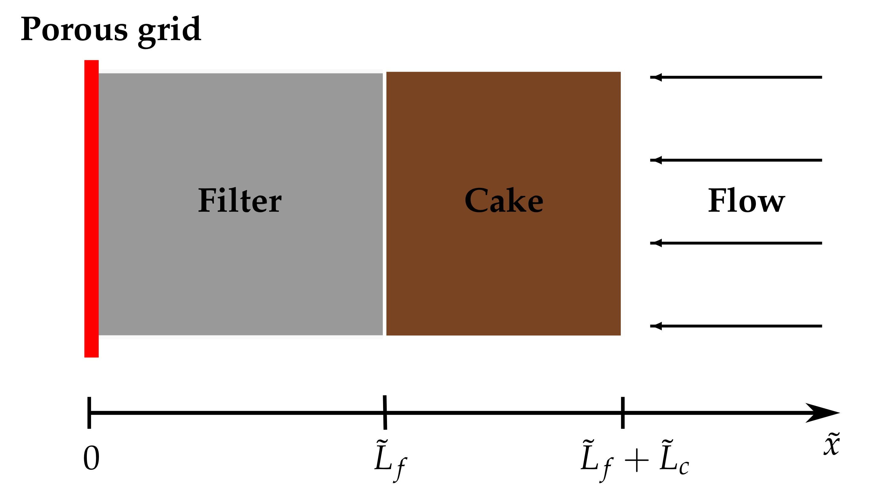
Employing the framework from Köry et al. [23], we introduce a spatial variable , impose an input pressure at and impose an output pressure at such that (see Figure 1). This results in a one-dimensional flow oriented in the negative direction. We denote to be the (positive) fluid flux through the filtercake per unit area and allow to vary with time but hold constant. We assume that all the particles are bigger than the pores in the filter.
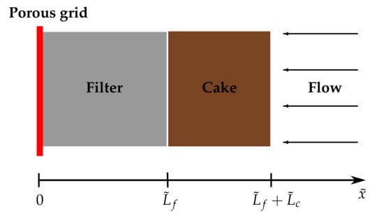
Figure 1.
Schematic set-up of the model for compressible filtercake.
Consider the feed solution (the mixture of fluid and particles) with a solid volume fraction assumed to be uniform in space and independent of time approaching the moving cake front at constant speed . During (an infinitesimal) time , the particles travel a distance and will cause a growth in the cake size . Since the particles move in the direction opposite to the cake growth, in this time interval a mass of volume has arrived at the cake from the feed where denotes the cross-sectional area of the cake. Taking into account particle packing in the cake with denoting the solid volume fraction in the cake in its strain-free state, this mass is transformed into a cake size increase of . Equating these two quantities, dividing by and taking the limit as gives
which may be rearranged to give
Finally, conservation of the fluid across the moving front requires that which upon substitution into (2) yields
Note that it is natural to assume that , as the particle packing in the feed fluid should always be less than that in the (strain-free) cake. We assume that once the particles arrive at the cake surface they become bound to the cake and cannot detach and re-enter the feed stream. Thus we do not consider the effects of concentration polarisation here. Because we assume that initially the system is clean so there is no cake we have as an initial condition. We are often interested in the throughput, , which is defined as the total volume of fluid processed per unit area of membrane at a given time, ,
Following Parker et al. [18] and Köry et al. [23], the permeabilities of the filter and of the cake are assumed to depend linearly on the strain , with denoting the displacement field of the material from its undeformed state, and will vary spatially as well as in time here, due to cake build-up. Thus we propose
where we have introduced a subscript i, which here and henceforth can attain two values, f or c, corresponding respectively to the filter domain, , and the cake domain, . Note that we assume that is a good approximation to the strain and this is because we are assuming deformations are small. We note further that, while in reality the permeability may possess a more complex relationship with the deformation, Equation (5) is an appropriate approximation in the small-deformation regime we are considering.
With this notation Darcy’s law, for slow viscous flow of a fluid through a porous material, is
where is the fluid pressure and the fluid viscosity. We assume the fluid to be incompressible, which implies that the flux is uniform in space (independent of ) for both the cake and the filter, and the continuity of flux at the filter–cake interface implies that .
2.1.2. Deformation
We assume small one-dimensional deformations and that the timescale of poroelastic response is much smaller than that of caking (similar to Herterich et al. [25]). Linear poroelasticity theory [26] then informs us that the displacement of the filter and cake can be modelled using a steady-state Navier equation extended by the Terzaghi term
where and denote the effective elastic constants of the filter and the cake (see Köry et al. [23] for details).
2.1.3. Boundary and Interfacial Conditions
We fix the end of the filter at using a porous grid that offers no resistance to the fluid flow and assume that the open end of the cake at is free. Then, the boundary conditions read
The equations governing and , Darcy’s law (6) and the Navier Equation (7), are, respectively, first- and second-order in space. Thus, to close the problem we impose continuity of fluid pressure, displacement and stress:
Altogether, this forms a moving boundary problem, with the moving boundary located at , with three unknown functions , and . This dimensional model depends on 13 parameters namely: , , , , , , , , , , , , , and one input function, . Note that there usually exists a one-to-one correspondence between the permeability and the solid volume fraction of a (strain-free) porous medium. This means that in our approach is not an independent parameter and, if needed, could be expressed as function of .
2.2. Nondimensionalisation
Denoting , we nondimensionalise as
for . These scalings are chosen to be natural to the model so that the resulting governing equation for the evolution of the cake thickness possesses the fewest number of parameters, as we shall observe subsequently (see Equation (30)). We introduce the following dimensionless quantities
We note that , and so, for convenience, we introduce and and use this from hereon whenever there is no ambiguity.
Using these scalings and notation the dimensionless filter and the cake regions are represented by and . The dimensionless cake-evolution equation is
Darcy’s law is
where
and the deformation of the two porous media is governed by the Navier equation
Continuity of fluid pressure and displacement at become the same conditions for the dimensionless variables, while the dimensionless form of the third interfacial condition from (9) is
For this choice of nondimensionalisation, the definition of throughput (4) indicates that and so the dimensionless throughput and the cake thickness are interchangeable. The dimensionless model depends only on four model parameters, namely, , , and , and one input function .
2.3. Model Restrictions
Using the same methodology as in Köry et al. [23], before solving the problem, we discuss the restrictions on model parameters required so that the small-deformations assumption is valid and so that shutdown is avoided. It can be shown (see Appendix A) that provided , and the small-deformations assumption holds in the filtercake for all times.
The filtercake will shut down if the permeability reaches zero at any point in the depth and this may occur in the filter or in the cake. We now explore the conditions on the dimensionless parameters and the pressure-drop evolution that allow us to avoid this shutdown behaviour.
2.3.1. Avoiding Filter Shutdown
We expect the maximum strain in the filter to occur at the porous grid . From (A2) and the form of the permeability function (15) this permeability will remain positive provided the applied transmembrane pressure
We note that and so we require
to avoid initial filter shutdown before any cake has deposited.
2.3.2. Avoiding Cake Shutdown
To avoid shutdown in the cake, the permeability from (15) needs to be positive everywhere in the cake, which is equivalent to
Integrating the Navier Equation (16) within the cake and using the boundary conditions (17b,d), we conclude for
which in combination with (21) yields
and this gives us a restriction to avoid shutdown in the cake. Note that the pressure distribution within the cake is not known a priori and must be determined as part of the solution.
2.4. Solution
We now analyse the dimensionless problem (13)–(18) to determine the solution. Substituting the expression for the pressure-gradient term from the Navier Equation (16) into Darcy’s law (14), integrating with respect to x and using the boundary condition (17d), we conclude
where is an integration constant. This constant can be determined using the continuity of stress at the filter–cake interface (18) (details of the calculations used throughout this section are presented in Appendix B) and we arrive at
Equation (24) is subsequently solved to give
Substituting the strain field from (26) into Darcy’s law (14), integrating and using the continuity of pressure across the filter–cake interface as well as appropriate boundary conditions, we arrive at an equation relating , and :
We further define
and note that these dimensionless parameters are natural extensions for the two porous media (filter and cake) of the dimensionless sensitivity parameter from Köry et al. [23]. These parameters characterise the sensitivity of the permeability of each porous medium to its deformation. While the precise values of will depend on the particular filter material and the contaminants that are being filtered, we may make some general observations on the values that may be taken. First, we note that both and must be positive. Second, we require in order that the filter does not shut down before any cake has been deposited (see Equation (20)). Third, we would usually expect the cake to be more deformable than the filter material. This means that we would expect the effective elastic constants, and , to be smaller for the cake than the filter, and so we would expect that . Recalling that, at , we have and , (27) provides an expression for the flux at given by
which is consistent with Equation (3.3) from Köry et al. [23]. Upon solving (27) for q, we substitute back into the cake-evolution Equation (13) to obtain
We have thus arrived at a first-order ordinary differential equation for the cake size with explicit dependencies on the model parameters. In summary the cake evolution depends on the input function , defined in (12), and two groupings of dimensionless parameters, and , defined in (28). Even though it is not straightforward to see the impact of individual parameters on cake size evolution, Equation (30) will be our starting point throughout Section 3 where we discuss industrial applications of our modelling framework. Furthermore, given arbitrary , and pressure evolution , one can obtain by numerically solving (30) (equipped with ). The cake-evolution Equation (13) then gives . The strain field may be inferred from (26), which can subsequently be integrated to give the displacement field using the boundary condition (17c).
Note that, in terms of the new dimensionless parameters from (28), the condition for avoiding filter shutdown (19) can be reformulated as
and the condition for avoiding cake shutdown (23) as
which needs to hold everywhere inside the cake. As the cake-evolution Equation (30) cannot be explicitly solved for arbitrary pressure-drop evolution , we do not have an explicit formula for the pressure distribution in the cake. To obtain a simple cake-shutdown condition in terms of variables that we keep track of (as opposed to the pressure ), we infer from the form of the permeability function (15), the strain field (26) and the definitions of the dimensionless parameters (28) that
and it follows that the cake shutdown is reached whenever
This condition will help us avoid cake shutdown on a case-by-case basis in Section 3, where we will use this theory to answer industrially motivated questions.
3. Industrial Applications
We now apply the theoretical framework that we have developed so far to industrially relevant problems. Specifically, we study three commonly employed filtration regimes—constant flux, greedy (where one wishes to achieve maximum total amount of fluid processed, or throughput, at any given time) and constant pressure drop. In each case, we aim to find the material properties of the filter (represented by the dimensionless parameter ) that optimise a given industrial goal for given material properties of the contaminant to be filtered (represented by the dimensionless parameter ).
3.1. Adaptive Pressure Drop to Obtain Constant Flux
A common operating regime in industry is to filter fluids at a constant flux. Enforcing a constant flux , we find, using (29), that
The solution to the cake-evolution Equation (30) that satisfies the initial condition is then
It can then be shown (see Appendix C) that the time evolution of the transmembrane pressure difference across the entire filtercake is given by
We note that in the limit of an incompressible filter, , which gives in (35), while (37) reduces to
We see that the transmembrane pressure difference rises with time, to maintain the constant flux as a result of the increased resistance offered by the build-up of the cake. Eventually the pressure will become sufficiently large such that, at a point in either the filter or the cake, the permeability will reach zero. Beyond this point, no further fluid may be processed while maintaining constant flux. In practice, filtration is conducted only until some threshold pressure (<1/) is reached.
3.1.1. Observations
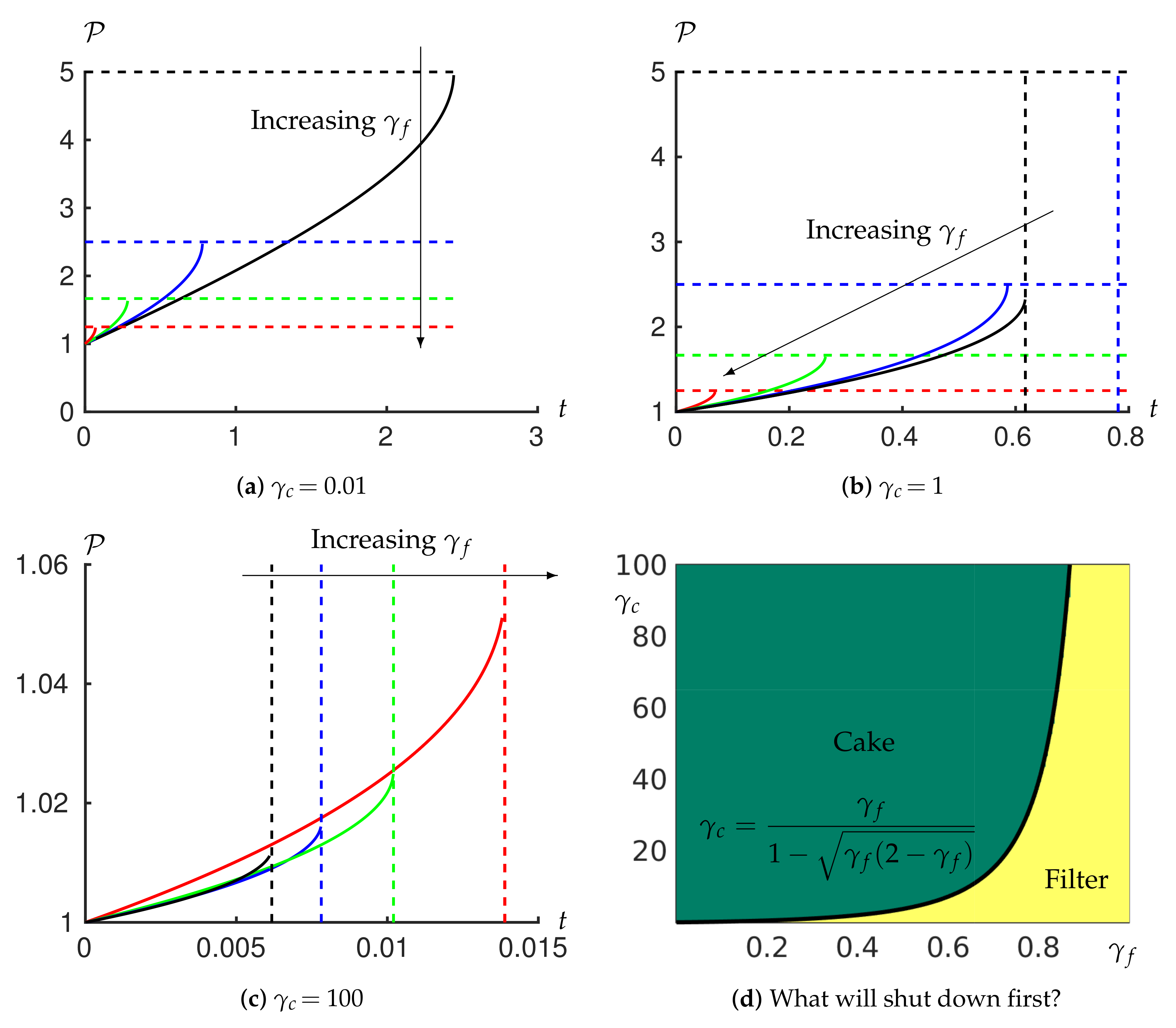
We now consider the behaviour of the system when it is operated in a constant flux regime using the model we have developed. For weakly compressible cakes (, Figure 2a) the higher the value of the sooner the shutdown occurs. The shutdown is first reached within the filter for any value of here. For a moderately compressible cake (, Figure 2b), while shutdown is reached in the filter for higher values of , we now find that shutdown occurs in the cake if is sufficiently low (). When the cake is very compressible (, Figure 2c) the shutdown always occurs in the cake. Furthermore, in this case, while the behaviour for different values of is similar at early time, at some point the pressure difference for the lowest value of (, black) overtakes that of the higher values of (0.4 and 0.6, blue and green curves respectively). This reflects the fact that the cake resistance is becoming the limiting factor (Figure 2c).
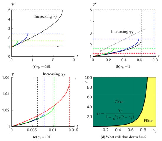
Figure 2.
Temporal evolution of the transmembrane pressure difference to maintain a constant flux for varying values of (black), (blue), (green) and (red), and for (a) (b) 1 and (c) 100. The horizontal dashed lines show the critical pressure at which the filter would shut down, Equation (31). The vertical dashed lines show the critical time at which the cake would shut down, Equation (41). We plot the pressure–time curve until one of these lines is reached. If the horizontal bound is reached first then the filter shuts down; if the vertical bound is reached first then the cake shuts down. (d) shows whether the shutdown occurs in the filter or in the cake depending on and . Note that varies over a much larger range than to capture the appropriate parameter space within which the transition occurs, which also reflects the fact that we expect the cake to be more compressible than the filter material in practice.
Note that, while in the case of incompressible filtercake, one needs to linearly increase pressure drop with time to maintain constant flux (cf. bottom-left subfigure of Figure 3 in Ripperger et al. [27]), when compression effects are taken into account, a superlinear growth of pressure drop is needed.
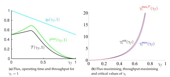
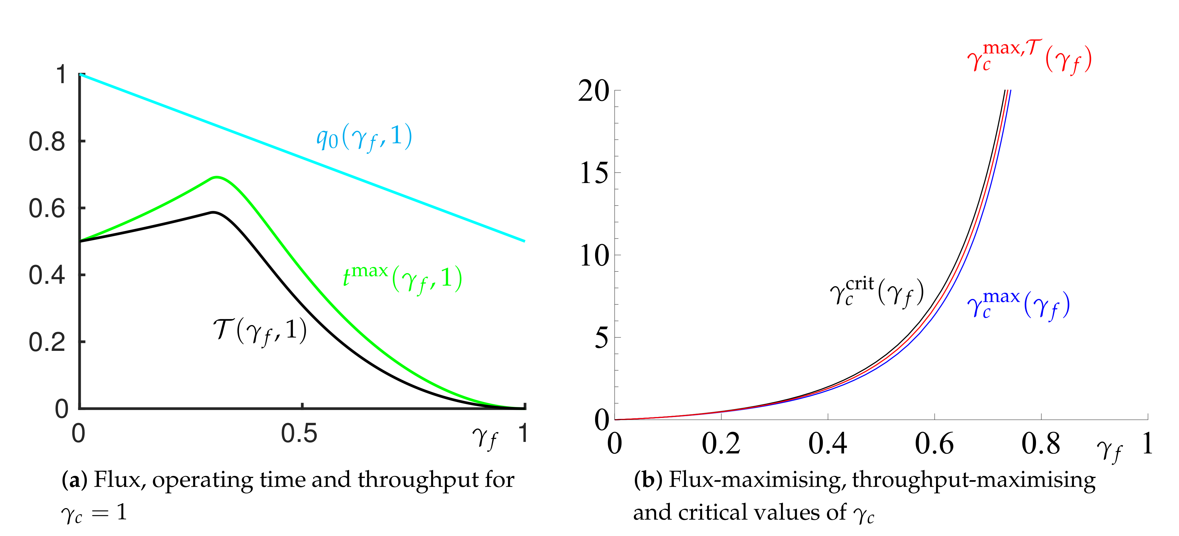
Figure 3.
(a) Flux, , given by (35) (cyan); maximum operating time, , given by (44) (green); and the maximum throughput, given by (45) (black). Here, . (b) The value of that: maximises the operating time, , given by (46) (blue); maximises the throughput, , given by (47) (red); and the critical value that separates cake or filter shutdown, , given by (42) (black).
Inspired by these observations, we now examine whether the shutdown under constant-flux filtration first occurs in the cake or in the filter.
3.1.2. Where and When Does the Shutdown Take Place?
To determine whether the shutdown occurs in the filter or the cake, and the time at which this occurs, we must first evaluate the strain and this can be determined from the strain field (26) using from (35) and . Using the results (35) and (36) as well as the definitions of dimensionless parameters from (28), this gives
Provided (which is required to avoid filter shutdown at , see (20)) the maximum strain within the filter continues to occur at (the porous grid) where it attains the value
Within the cake the maximum strain occurs at where the value is attained. It is easy to see that both the maximum compression within the filter and that within the cake increase with time. We conclude that the shutdown might either occur in the filter at time satisfying
(provided we have not yet reached shutdown in the cake) or in the cake at time satisfying
provided we have not yet reached shutdown in the filter. After some algebraic manipulations of (40) and (41) (see Appendix D) we conclude that the boundary separating shutdown in the cake and in the filter can be expressed as a critical value for the cake properties, for given filter properties given by
We conclude that if , shutdown occurs in the cake, while if , shutdown occurs in the filter (see Figure 2d). Inverting (42) provides the critical filter properties that separate cake or filter shutdown for a given cake properties given by
Finally the analysis in Appendix D gives that the maximum operating time given by
The total throughput, , is obtained by multiplying this quantity by the flux, given by (35), so that
3.1.3. Optimisation
We now use the expressions (35), (44) and (45) to determine optimal values for and for the system operating at constant flux. We start by allowing the system to run until it shuts down and consider how the throughput might be maximised.
Figure 3a shows that, for a given contaminant, characterised by , for small we can increase the time before shutdown by increasing . At the same time the flux decreases as increases. However this penalty does not outweigh the advantages gained by the increased operating time, and so the total throughput, given by (45) also increases with increasing (Figure 3a).
This increase in throughput is due to the more compressible filter acting as a ‘mattress’, taking up some of the pressure drop and compression that would otherwise be carried by the cake and preventing the cake from shutting down. However, if we increase too far then the filter becomes too compressible and shuts down before the cake, leading to a reduction in total processing time. Figure 3a indicates that for both the total throughput and the maximum operating time are maximised at .
We can further determine expressions for the filter properties that lead to the corresponding maximisations. First, the value of that maximises the operating time can be obtained by differentiation of (44), equating the resulting expression to zero and solving for . This gives
Second, the value of that maximises the total throughput can similarly be shown to satisfy
In Figure 3b it can be seen that, for a given , both the time-maximising and the throughput-maximising values of are in the filter-shutdown region and very close to the critical value at which the filter and cake shut down simultaneously. These observations suggest that choosing a filter compressibility that is close to that for which we would observe simultaneous filter and cake shutdown would lead to maximum throughput before shutdown.
From these relationships we confirm that, for given cake properties (characterised through ), a filter with properties (characterised by ) that correspond to the threshold between cake and filter shutdown leads to a system that is very close to that which maximises both the operating time and the total throughput (Figure 3b). This does indeed confirm that, given a particular material to filter, choosing the filter properties such that both the cake and filter shut down at the same time (given by (43)), will lead to a system that is close to maximising the total operating time and final throughput. This offers a simple way of identifying an optimal filter selection.
3.1.4. Minimising Power Expenditure
Previously we discussed maximising throughput but another desirable industrial outcome is to minimise the total energy used per unit area of membrane required to generate a given flux. The total power per unit membrane cross-sectional area expended on the filtration is the product of the flux q (here ) and the pressure difference . A measure of the total energy, , used at time t, is the time integral of this:
This may be evaluated using (44), (35) and (37), but while the result is analytic, it is cumbersome so we do not write it here.
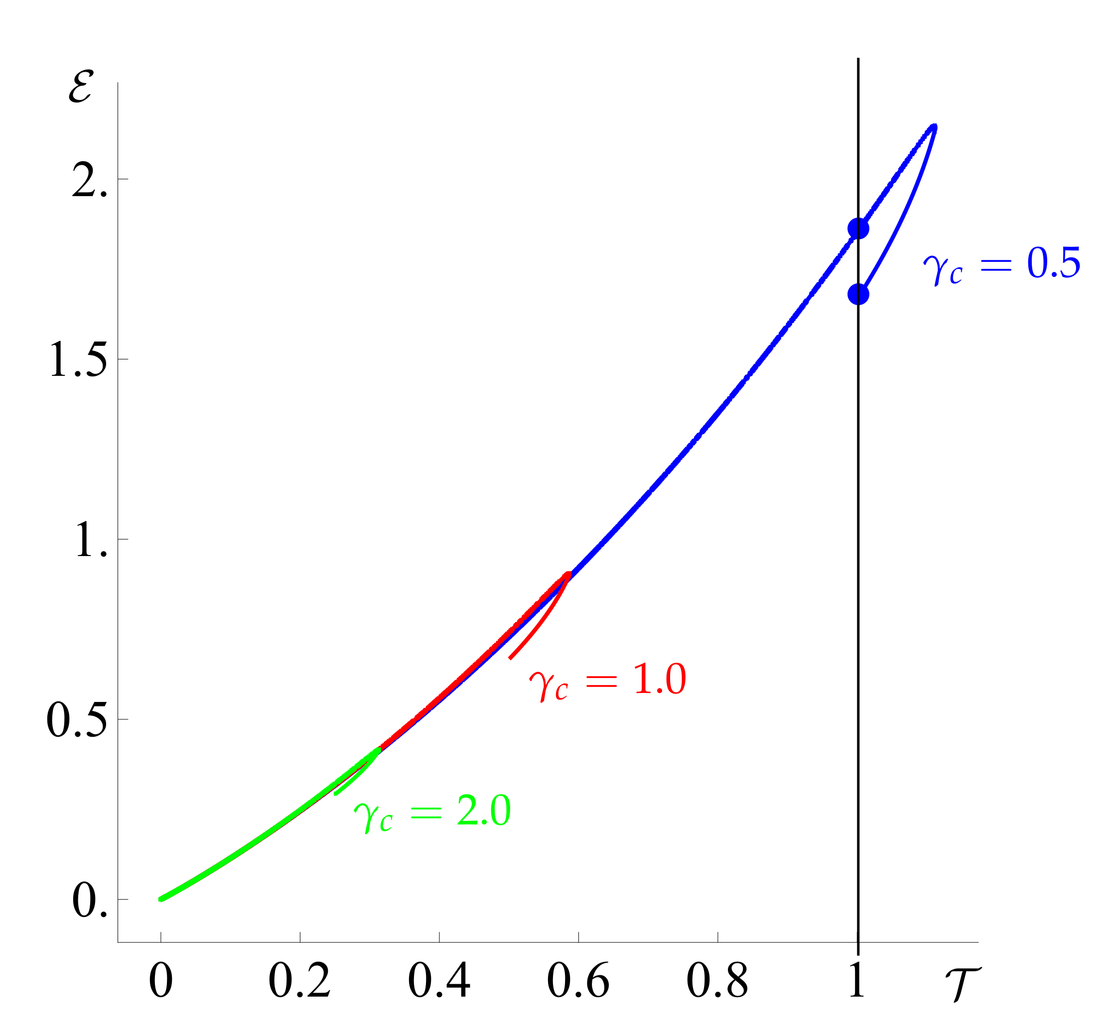
Setting yields filter shutdown at , resulting in , which trivially minimises the power expenditure. Therefore, we cannot minimise the expended power while maximising the throughput, and we thus consider trade-offs similar to those described in Köry et al. [23]. However, for a given , we find that varying leads to a multi-valued energy when plotted versus the throughput (see Figure 4). This indicates that, in some cases, the same final throughput can be achieved for less energy by choosing a more rigid filter, that is, one with a lower value of .
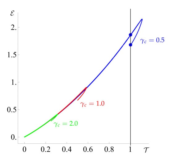
Figure 4.
The energy expended to achieve a given final throughput. We notice that the graph is multivalued in some places, indicating that the same final throughput may be achieved by using less energy. Here, (blue), 1 (red) and 2 (green) and the curves are generated by varying . The turning points of these curves correspond to the values of that maximise the throughput.
3.2. Adjusting the Pressure Drop to Achieve Maximum Throughput at All Times
Let us now consider the operational regime where we want to filter a given amount of fluid as quickly as possible and we can vary the flux by changing the applied pressure. At any given instant in time, the transmembrane pressure must be below a critical value to avoid shutdown of the system. Here, we will derive an expression for the transmembrane pressure difference that maximises the flux at any time, noting that avoiding shutdown of the system requires us to be below the pressure that causes shut down of both the filter and the cake. We expect that maximising the flux at each time will maximise the throughput. We will assume that we are constrained initially to avoid shutdown in the filter and then check if and when shutdown in the cake becomes the limiting constraint.
To begin with, when the cake thickness is small, we will always be limited by the critical pressure that induces filter shutdown. This is given by from (31). Note from (12) that , which means that here needs to be understood as an instantaneous switch of the dimensionless pressure drop from 1 to at . Substituting this into the cake-evolution Equation (30) and simplifying the resulting expression, the cake evolution equation takes the form
Upon rewriting and integrating, we obtain an implicit relation for the cake thickness at a given time t,
where we have applied . We continue operating with unless we reach shutdown in the cake. Substituting the right-hand side from the cake-evolution Equation (30) for q into the cake-shutdown condition (34), we find that there are no positive solutions for when and one positive solution,
for . Substituting (51) into (50) provides the transition time before which the system is on the brink of shutdown in the filter and after which the cake deformation limits the pressure drop. We conclude that, if , continuing indefinitely with a transmembrane pressure of will provide the maximum flux. In this case, it follows from (50) that the cake size will increase unboundedly. This is because we have here, and the condition for avoiding cake shutdown (32) is thus always satisfied. If , however, the constant transmembrane pressure would cause the cake to grow, the filter–cake interface pressure to decrease, and eventually the cake to shut down (i.e., condition (32) would cease to be true in finite time). In such a case, we maximise the flux at any given time by applying a transmembrane pressure until the cake size reaches the value given by (51), following which we enter a second phase where we decrease the pressure drop in such a way that the flux is given by (34) to ensure that the cake does not shut down.
Using the cake-evolution Equation (13) and substituting for q from (34), we conclude that the cake evolution equation during this second phase reads
Solving this subject to the condition gives
In order to determine how one should vary to achieve the maximum flux at any time for after the critical value of from (51), we equate the right-hand side of the cake-evolution equation (30) and that of (52) and solve for to get
where we chose the appropriate solution of the quadratic for which so that we do not have shutdown in the filter. Substituting (53) into (54) gives the maximum pressure that we can apply without the system shutting down for times when the cake (rather than the filter) deformation begins to constrain the pressure drop. Substituting (53) into (52) gives the corresponding flux q.
As a special case, note that for an incompressible filter (), we find that, for all , and . An incompressible filter maximises the throughput that can be achieved by any filter up to any positive time. Finally, note that whenever , as (i.e., ), we get . This is consistent with Equation (32)), which ensures we do not reach shutdown in the cake, because must be non-negative. Note further that as under the throughput-maximising strategy, the cake size increases without bounds so the resistance of the filter becomes negligible compared to that of the cake, which (provided for all times) results in . This explains why must converge to as .
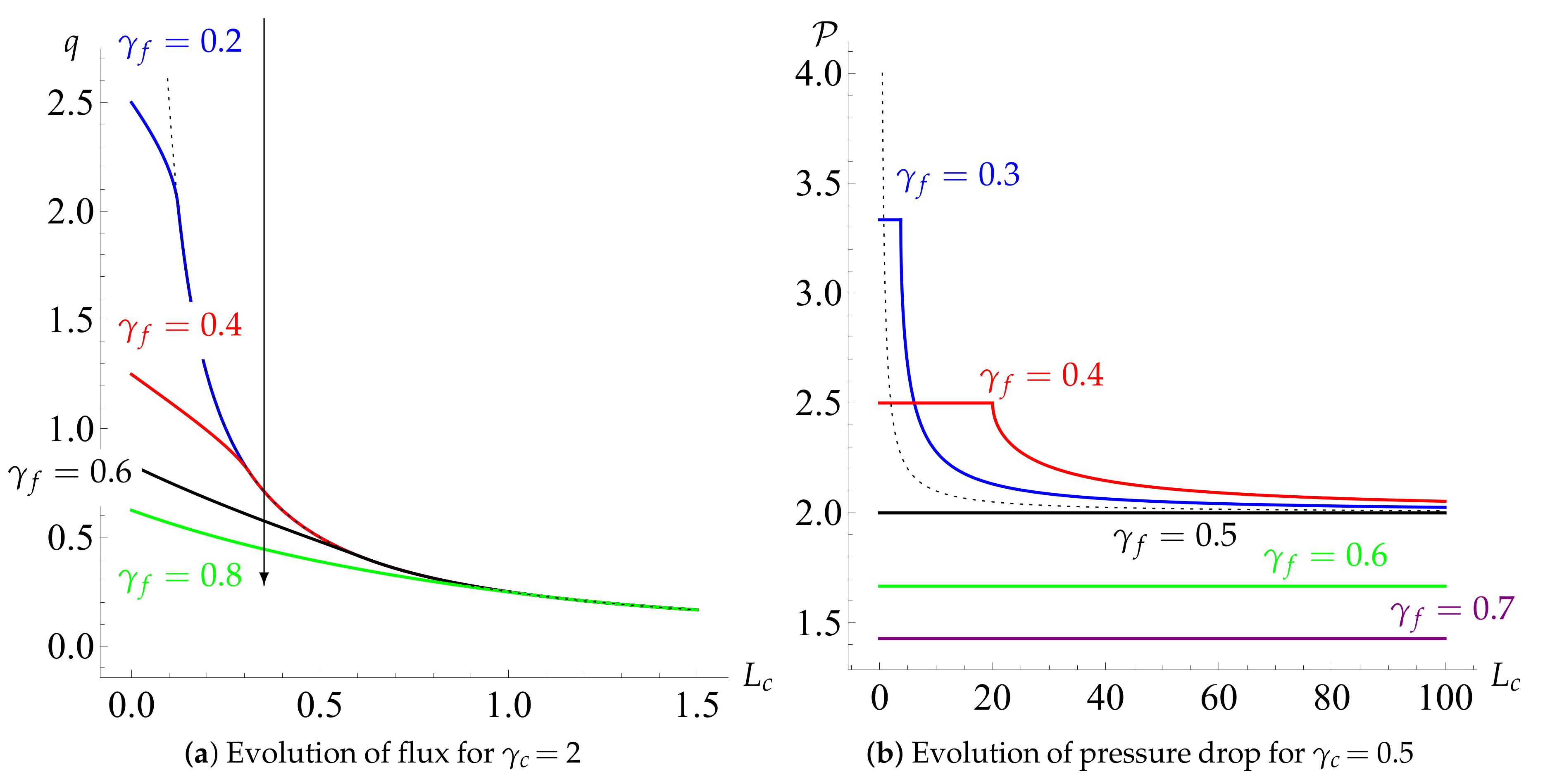
In Figure 5a,b we show the evolution of and q as functions of cake size , which acts as a proxy for time, for different values of and . We find that, for any , one reaches any given value of (and thus filters any given amount of fluid) in the shortest time by choosing an incompressible filter, .
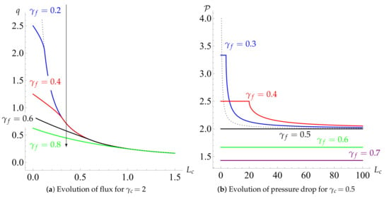
Figure 5.
(a) The maximum flux, q, that can be achieved without the system shutting down, versus cake thickness, , for and (blue), 0.4 (red), 0.6 (black) and 0.8 (green). The black dotted line represents the incompressible-filter limit () and the arrow indicates the direction of increasing . These curves are generated using Equations (49) and (52). (b) The evolution of transmembrane pressure with cake size that achieves the maximum flux at any time without system shutdown, with .
3.3. Behaviour for Fixed Pressure Drop
Finally, we study the operational regime where a constant pressure drop is applied across the filtercake and the flux therefore changes. We have already shown that for the threshold pressure drop can be maintained for all positive times t, so it follows that any constant pressure drop below this value (including ) can also be maintained indefinitely. Thus, we solely concentrate on the case where , for which the threshold pressure drop would result in finite-time cake shutdown.
In a similar manner to the previous section, we can find an implicit relationship for the dependence of cake size on time t. The expression is, however, rather cumbersome, and so instead we focus on the cake shutdown. Substituting into the right-hand side of the cake-evolution Equation (30), equating this expression with the cake shutdown condition for the flux (34) and solving for , we get (assuming ) no finite positive solutions for and one positive solution
for . This implies that for one can maintain such pressure drop indefinitely, while for , the filtration under constant pressure drop ends in finite time. It follows from (55) that, for any chosen , one achieves maximal throughput by designing a filter with the largest possible so that filter shutdown is avoided, that is, . With such , the throughput from (55) becomes
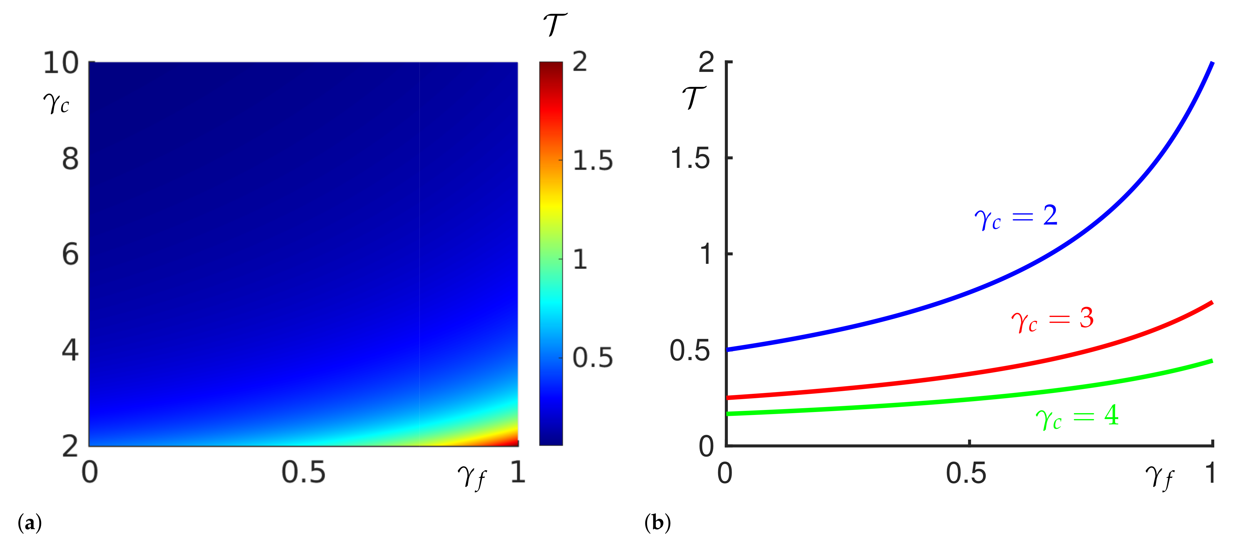
This observation is confirmed in Figure 6, where we find that, if one wishes to maximise the total throughput before shutdown for arbitrary , then it is best to choose a filter with , and the result (56) provides an upper bound on the expected throughput.
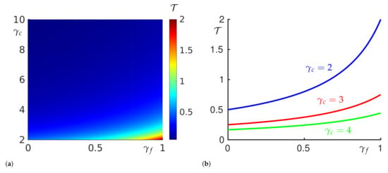
Figure 6.
(a) Total throughput as a function of and . (b) Total throughput as a function of for (blue), 3 (red) and 4 (green). For all values of , maximum throughput is achieved by choosing a filter with .
Finally, note that while the throughput at any time is given by (provided we avoid shutdown), the power expended on such filtration process up to time t is given by
This explicitly states the trade-off between the minimisation of power expenditure and the maximisation of throughput.
4. Discussion
In this paper we considered fouling of filters due to cake formation during dead-end filtration. We focused on the particular idea that both the cake and the underlying membrane may deform elastically during a filtration process and thus the interplay between the two may play an important role during filtration processes. We applied a poroelastic model introduced in Parker et al. [18] and further studied in Köry et al. [23] to the caking process. Both the filter and the cake were considered to be compressible porous media, where their permeabilities were assumed to vary linearly with the local strain, and the flow and deformations were taken to be one dimensional.
Using analytical methods, we determined the condition for filter shutdown (31) and derived an equation for the growth of the cake that depended on only the pressure drop and two dimensionless parameters that measured the mechanical sensitivities of the cake and filter. This provides a novel cake-filtration law as the flux through the filtercake is given explicitly as a function of the pressure drop . Even though the equation for the growth of the cake layer cannot be solved for a general pressure drop, we made considerable analytical progress by considering three industrially relevant operating regimes of constant flux, maximising flux, and constant pressure-drop filtration.
To maintain a constant flux through the filtercake it is necessary to increase the applied pressure drop gradually. At some point the pressure drop will be such that either the filter or the cake will shut down. We found the required evolution of the pressure drop to maintain a constant flux and subsequently identified the parameter dependence that leads to either filter or cake shutdown. We proceeded to study the maximum operating time and throughput achievable and showed that, for given cake properties, the largest throughput is achieved with a slightly compressible filter, which acts as a mattress, taking some of the pressure drop and compression away from the cake. The effective elastic coefficients, and , of the optimal filter must be chosen slightly below the coefficients that cause the filter and the cake to shut down simultaneously. We concluded the constant-flux analysis by considering a minimisation of the power costs. Here, we noticed that, even though we can obtain higher throughput by allowing the filter to be compressible, it comes at the cost of significantly increased power expenditure, so trade-offs between throughput and power consumption, similar to those studied in Köry et al. [23], should be taken into account.
We then analysed the operational regime where we maximise the flux (and thus throughput) at every time during the filtration process, regardless of power expenditure. We derived an implicit relationship for the cake size as a function of filtration time. We found that, if the compressibility of the filter was at least as large as that of the cake, a constant pressure drop (just below that which causes filter shutdown) could be maintained indefinitely without reaching shutdown in the cake. If the filter is more rigid than the cake, however, the maximum pressure that can be applied without the filtercake shutting down falls with time and we found an explicit expression for this dependence. For any cake properties, choosing an incompressible filter was shown to maximise throughput at all times.
Finally, we studied the operational regime of a constant applied pressure drop. We found that, for given material properties, there exists a critical pressure below which we can operate a system indefinitely without the filtercake shutting down. If we wish to maximise throughput for given cake properties at a pressure drop above this critical value, it is optimal to choose a filter that is highly compressible so that it is able to take some of the pressure drop and compression from the cake.
The work in this paper demonstrates how the resistance and deformation of both the cake and the underlying filter medium can play an important role when thinking about optimising the process of dead-end filtration with cake build-up. The main objective of this work was to present a simple model that was able to demonstrate the type of behaviour that can be exhibited in a system comprising a membrane and cake that both deform elastically. A key next step in this work would be to generalise the ideas to account more accurately for the filtration of specific materials. Specifically, this would involve using nonlinear compressional rheology modelling. In doing so, the system may be described by an elastic membrane with a plastically deforming cake. It would also be interesting to account for particle trapping in the interior of the filter medium. In addition it would be of interest to study the case where the particles that build up to form the cake remain free so that if the flow is switched off the cake can deplete. In this scenario, one would also need to model the effects of concentration polarisation. Finally, experiments need to be conducted to validate or disprove the implications of this theory.
Author Contributions
Conceptualization, A.U.K., C.P.P. and I.M.G.; methodology, J.K. and A.U.K.; formal analysis, J.K. and A.U.K.; investigation, J.K. and A.U.K.; writing—original draft preparation, J.K. and A.U.K.; writing—review and editing, J.K., A.U.K., C.P.P. and I.M.G.; supervision, C.P.P. and I.M.G.; funding acquisition, C.P.P. and I.M.G. All authors have read and agreed to the published version of the manuscript.
Funding
J.K. is grateful to the Royal Society for financial support. A.U.K. was funded by EPSRC. I.M.G. gratefully acknowledges support from the Royal Society through a University Research Fellowship.
Informed Consent Statement
Not applicable.
Data Availability Statement
Data available at people.maths.ox.ac.uk/griffit4/data/kory_modelling_2021.html.
Conflicts of Interest
The authors declare no conflict of interest.
Appendix A. Sufficient Conditions Ensuring Small Deformations
To ensure small deformations in the filter we note that, due to the boundary condition (17c), it is sufficient to show that
Integrating the Navier Equation (16) and using the continuity of stress (18), we obtain
and this value represents the largest compression within the filter. Using the boundary condition (17c) we then get
and (A1) is thus satisfied provided
Small deformations in the filter can then be enforced provided and for all times t.
To ensure small deformations in the cake, we need to make sure that
Integrating the Navier Equation (16) across the cake and using the boundary condition (17d), we get
and using this as an upper bound for compression within the cake, we conclude
Therefore, the condition (A5) is satisfied, if we have
We conclude that the assumption (with ) ensures small deformations in the cake for all times.
Appendix B. Details of the Solution Process
The solution of (24) reads
where the sign in (A10) has been chosen to satisfy the boundary condition (17d), and the sign in (A9) has been chosen so that we restrict our attention to the (physically relevant) region in , which follows from requiring that the filter permeability is non-negative everywhere (otherwise we have shutdown and our model is no longer valid). Applying the continuity of stress at (18), we conclude (25) must hold and this then yields the strain field (26). Substituting (26) back into Darcy’s law (14) yields
Integrating the pressure over the two respective regions, using its continuity across as well as boundary conditions (17a,b), we find (27) is valid. It then follows (using the dimensionless parameters from (28)) that
Squaring both sides of (A11), denoting , and manipulating gives
Once again, we square both sides of (A12) and using elementary algebra, we conclude
which is quadratic in q. Upon algebraic simplification of the discriminant, the solutions read
To determine which sign gives the relevant solution, we evaluate q at (where and ) to get
Recalling the initial flux value from (29) as well as the definition of from (28), we conclude that if , we have to choose the positive sign, and if , we have to choose the negative sign in (A1). The time evolution of the (undeformed) cake size is then determined by substituting back into the cake-evolution Equation (13) and we get
Dividing both numerator and denominator by and recalling the definition of G, we conclude (30) is valid.
Appendix C. Pressure Drop Needed to Maintain Constant Flux
We start by noting that the right-hand side of the cake-evolution Equation (30) equals the flux q (which we assume to be independent of time here), then we denote
and multiplying by the denominator, we get
which gives
Squaring (A16), and introducing the notation
and get
which is a quadratic equation in H. The solution to this equation reads
Appendix D. Constant-Flux Filtration: Comparing the Times of Cake and Filter Shutdown
Using algebraic manipulation, the filter-shutdown condition (40) becomes
which upon squaring and further algebra gives
Solving this as a quadratic equation in t yields
where we still need to determine the sign because by squaring (A21), we might have obtained new roots. We now check whether the signs of the right- and left-hand sides of (A21) agree. Note, once the sign is resolved, the shutdown time is then given by the minimum of non-negative values from (A23) and we conclude by comparing this minimum with the cake shutdown time from (41).
As the square root on the left-hand side of (A21) is multiplied by , we now split the analysis into two cases: and .
Case 1. γf/γc ≥ 1
Here, the RHS of (A21) needs to be non-positive at the time of filter shutdown, that is,
which is equivalent to
We see that from (A23) satisfies (A21) and is non-negative. Therefore, as , the shutdown in filter will occur at , provided shutdown has not occurred in the cake before that, that is, provided from (41) is greater than from (A23). One trivially has
from which it follows that
This implies that when , the value of is always smaller than and shutdown will happen in the filter at from (A23).
Case 2. 0 < γf/γc < 1
For any solution of (A23) to also solve (A21), we need the RHS of (A21) to be non-negative, that is,
which is true if and only if
Thus we see that the only available solution is the one with a positive sign, and for inequality (A29) to hold, we then need
which under our constraint leads to
Viewing this as a quadratic inequality in we conclude that, under our constraint , the inequality (A29) with from (A23) holds if
This implies that, for , the filtration process ends with a cake shutdown at the maximum operating time from (41). from (A23) can be shown to be non-negative if and only if
from which it immediately follows that for every and satisfying (A32), the value of is indeed non-negative. For such and , it then remains to compare with . Clearly,
and expanding this we get
and it therefore follows that .
References
- Ding, B.; Li, C.; Zhang, M.; Ji, F.; Dong, X. Effects of pore size distribution and coordination number on the prediction of filtration coefficients for straining from percolation theory. Chem. Eng. Sci. 2015, 127, 40–51. [Google Scholar] [CrossRef]
- Charcosset, C. Membrane processes in biotechnology: An overview. Biotechnol. Adv. 2006, 24, 482–492. [Google Scholar] [CrossRef]
- Mulder, J. Basic Principles of Membrane Technology; Springer: Dordrecht, The Netherlands, 1996. [Google Scholar]
- King, J.R.; Please, C.P. Asymptotic analysis of the growth of cake layers in filters. IMA J. Appl. Math. 1996, 57, 1–28. [Google Scholar] [CrossRef]
- Sanaei, P.; Richardson, G.W.; Witelski, T.; Cummings, L.J. Flow and fouling in a pleated membrane filter. J. Fluid Mech. 2016, 795, 36–59. [Google Scholar] [CrossRef]
- Buscall, R.; White, L.R. The consolidation of concentrated suspensions. Part 1. The theory of sedimentation. J. Chem. Soc. Faraday Trans. 1 Phys. Chem. Condens. Phases 1987, 83, 873–891. [Google Scholar] [CrossRef]
- Landman, K.A.; White, L.R.; Eberl, M. Pressure filtration of flocculated suspensions. AIChE J. 1995, 41, 1687–1700. [Google Scholar] [CrossRef]
- Landman, K.A.; White, L.R. Predicting filtration time and maximizing throughput in a pressure filter. AIChE J. 1997, 43, 3147–3160. [Google Scholar] [CrossRef]
- Kapur, P.C.; Laha, S.; Usher, S.; de Kretser, R.G.; Scales, P. Modeling of the consolidation stage in pressure filtration of compressible cakes. J. Colloid Interf. Sci. 2002, 256, 216–222. [Google Scholar] [CrossRef]
- Stickland, A.D.; Irvin, E.H.; Skinner, S.J.; Scales, P.J.; Hawkey, A.; Kaswalder, F. Filter press performance for fast-filtering compressible suspensions. Chem. Eng. Technol. 2016, 39, 409–416. [Google Scholar] [CrossRef]
- Stickland, A.D.; Skinner, S.J.; Cavalida, R.G.; Scales, P.J. Optimisation of filter design and operation for wastewater treatment sludge. Sep. Purif. Technol. 2018, 198, 31–37. [Google Scholar] [CrossRef]
- Hewitt, D.R.; Paterson, D.T.; Balmforth, N.J.; Martinez, D.M. Dewatering of fibre suspensions by pressure filtration. Phys. Fluids 2016, 28, 063304. [Google Scholar] [CrossRef]
- Eaves, T.S.; Paterson, D.T.; Hewitt, D.R.; Balmforth, N.J.; Martinez, D.M. Dewatering saturated, networked suspensions with a screw press. J. Eng. Math. 2020, 120, 1–28. [Google Scholar] [CrossRef]
- Stickland, A.D.; de Kretser, R.G.; Scales, P.J. One-dimensional model of vacuum filtration of compressible flocculated suspensions. AIChE J. 2010, 56, 2622–2631. [Google Scholar] [CrossRef]
- Terzaghi, K. Theoretical Soil Mechanics; John Wiley & Sons: New York, NY, USA, 1943. [Google Scholar]
- Biot, M.A. General theory of three-dimensional consolidation. J. Appl. Phys. 1941, 12, 155–164. [Google Scholar] [CrossRef]
- Kenyon, D.E. A mathematical model of water flux through aortic tissue. Bull. Math. Biol. 1979, 41, 79–90. [Google Scholar] [CrossRef]
- Parker, K.H.; Mehta, R.V.; Caro, C.G. Steady flow in porous, elastically deformable materials. J. Appl. Mech. 1987, 54, 794–800. [Google Scholar] [CrossRef]
- MacMinn, C.W.; Dufresne, E.R.; Wettlaufer, J.S. Fluid-driven deformation of a soft granular material. Phys. Rev. X 2015, 5, 011020. [Google Scholar] [CrossRef]
- MacMinn, C.W.; Dufresne, E.R.; Wettlaufer, J.S. Large deformations of a soft porous material. Phys. Rev. Appl. 2016, 5, 044020. [Google Scholar] [CrossRef]
- Hewitt, D.R.; Nijjer, J.S.; Worster, M.G.; Neufeld, J.A. Flow-induced compaction of a deformable porous medium. Phys. Rev. E 2016, 93, 023116. [Google Scholar] [CrossRef]
- Collis, J.; Brown, D.L.; Hubbard, M.E.; O’Dea, R.D. Effective equations governing an active poroelastic medium. Proc. R. Soc. A Math. Phys. Eng. Sci. 2017, 473, 20160755. [Google Scholar] [CrossRef]
- Köry, J.; Krupp, A.U.; Please, C.P.; Griffiths, I.M. The effect of compressibility on the behaviour of filter media. IMA J. Appl. Math. 2020, 85, 564–583. [Google Scholar] [CrossRef]
- Lee, D.J.; Wang, C.H. Theories of cake filtration and consolidation and implications to sludge dewatering. Water Res. 2000, 34, 1–20. [Google Scholar] [CrossRef]
- Herterich, J.G.; Griffiths, I.M.; Vella, D. Reproducing the pressure–time signature of membrane filtration: The interplay between fouling, caking, and elasticity. J. Membr. Sci. 2019, 577, 235–248. [Google Scholar] [CrossRef]
- Howell, P.; Kozyreff, G.; Ockendon, J. Applied Solid Mechanics; Cambridge University Press: Cambridge, UK, 2009; Volume 43. [Google Scholar]
- Ripperger, S.; Gösele, W.; Alt, C.; Loewe, T. Filtration, 1. Fundamentals. In Ullmann’s Encyclopedia of Industrial Chemistry; Wiley: Hoboken, NJ, USA, 2000; pp. 1–38. [Google Scholar]
Publisher’s Note: MDPI stays neutral with regard to jurisdictional claims in published maps and institutional affiliations. |
© 2021 by the authors. Licensee MDPI, Basel, Switzerland. This article is an open access article distributed under the terms and conditions of the Creative Commons Attribution (CC BY) license (http://creativecommons.org/licenses/by/4.0/).

