Abstract
Human-exoskeleton misalignment could lead to permanent damages upon the targeted limb with long-term use in rehabilitation. Hence, achieving proper alignment is necessary to ensure patient safety and an effective rehabilitative journey. In this study, a joint-based and task-based exoskeleton for upper limb rehabilitation were modeled and assessed. The assessment examined and quantified the misalignment present at the elbow joint as well as its effects on the main flexor and extensor muscles’ tendon length during elbow flexion-extension. The effects of the misalignments found for both exoskeletons resulted to be minimal in most muscles observed, except the anconeus and brachialis. The anconeus muscle demonstrated a relatively higher variation in tendon length with the joint-based exoskeleton misalignment, indicating that the task-based exoskeleton is favored for tasks that involve this particular muscle. Moreover, the brachialis demonstrated a significantly higher variation with the task-based exoskeleton misalignment, indicating that the joint-based exoskeleton is favored for tasks that involve the muscle.
1. Introduction
Exoskeletons are commonly used to automate and assist with exercises in physical rehabilitation. The incorporation of these devices to rehabilitation has provided several benefits to physical therapists and patients. For instance, exoskeletons have shown to remove the physical load from the therapists, leading to longer and more intensive training periods [1]. Moreover, the use of exoskeletons has motivated the active involvement from the patient, which has resulted in a more effective and rapid recovery [2]. Since exoskeletons have proved to be beneficial in physical rehabilitation, rehabilitative-exoskeleton development and evolution has continued to be a motivated research area.
Exoskeleton designers and developers face an ongoing challenge in achieving perfect alignment of these robotic devices with the human body and targeted limbs. While some degree of misalignment is inevitable due to the complexity of the human body, proper alignment is crucial to avoid complications such as discomfort and irreversible damage to the user [3]. Research has shown that human-exoskeleton misalignment generates parasitic forces on the user’s targeted limb, which alters the desired motion needed for proper movement during rehabilitation exercises [4]. Although there have been several attempts that target this ongoing issue, the solutions tend to disregard aspects of the factors that continue to contribute to these challenges, such as subject variability, simplification of complex human joints, and generalization of the human body’s range of motion.
The most common approach in exoskeleton design is the joint-based approach, which involves mechanically replicating the structure of the human body. However, this approach presents its own challenge due to the complexity of human joints. Typically, complex joints, such as the shoulder and elbow joints, are modeled as ball-and-socket joints and hinges, respectively. However, this design approach assumes that the set of joints rotates about a fixed axis, whereas human joints allow for complex motions that result in displacement of their center of rotation [5]. Failure to align these robotic devices with the anatomical structure of the human body could cause constraint and stress on the targeted joints and limbs, potentially leading to detrimental effects on the user. The difficulty of mechanically replicating human joints in exoskeleton designs has motivated other approaches, such as the task-based design approach, which focuses on generating a specific task without necessarily mimicking the human body. However, this approach may also present misalignment issues due to its lack of control and support at the targeted human joint, potentially leading to dangerous motions such as varus-valgus rotations at the elbow joint.
Previous studies have sought to identify any misalignment upon developed exoskeleton designs through prototype testing and computational modeling. For instance, the study demonstrated in [6] performed prototype testing to determine any inconsistencies between the human range of motion and that of their developed exoskeleton. Other studies such as [7] were designed to assess an exoskeleton’s ability to account for human variability and alignment to the human body using a model-based assessment method to compare the kinematics of the subjects and exoskeleton and then identify any parasite forces acting on the targeted limb. However, this method of assessment does not allow for the quantification of the identified misalignment and its effect on the targeted limb. Other approaches in assessment have been performed using the OpenSim musculoskeletal modeling software to predict the dynamic behavior between an exoskeleton and its user [8]. Similarly, this method of assessment does not include a quantified assessment on the internal effects that the identified misalignment presents on the user’s targeted limb. Overall, the OpenSim 3.3 software has not been used as a means to quantify misalignment and its effect on the internal components of the targeted limb other than the assessment method developed in [9]. However, this method only focuses on providing an assessment for joint-based exoskeleton designs. Hence, an assessment method to quantify misalignment on task-based exoskeleton designs and its effects on the targeted limb is required to determine if an identified misalignment could lead to detrimental effects upon the user, which could then motivate the development of exoskeletons with acceptable levels of misalignment.
In this research, the joint-based and task-based exoskeleton designs are evaluated and compared in terms of their alignment to the human elbow joint using OpenSim. The study aims to quantify any misalignment present in the designs and determine its effects on the muscle-tendon length of the main elbow flexor-extensor muscles during simulated elbow flexion-extension motion [9]. Misalignment between the human and exoskeleton can generate undesired forces on the targeted limb, which may impact muscle performance and cause injury or discomfort to individuals with impairments. This research goes beyond previous work by introducing an alternative method for quantifying misalignment in a task-based exoskeleton and identifying detrimental levels of misalignment. By observing variations in muscle tendon lengths, this study aims to determine if undesired forces are influencing muscle performance and potentially causing injury or discomfort.
2. Exoskeleton Descriptions
Since this study performs an assessment method on a task-based and joint-based exoskeleton, both mechanisms are introduced and described to elaborate on their differences in design and mechanical abilities.
2.1. Joint-Based Exoskeleton
The joint-based exoskeleton is a 5 Degree-of-Freedom (DOF) mechanism designed to assist with upper limb rehabilitation [10]. As shown in Figure 1, the mechanism is composed of five links, where link 1, 4, and 5 are adjustable to account for anthropometric variability between users. An adjustable stand is also included to account for user height variability. The overall mechanism is composed of five active joints that are able to generate different rehabilitation motion tasks such as shoulder flexion-extension, shoulder adduction-abduction, shoulder elevation-depression, and elbow flexion-extension.
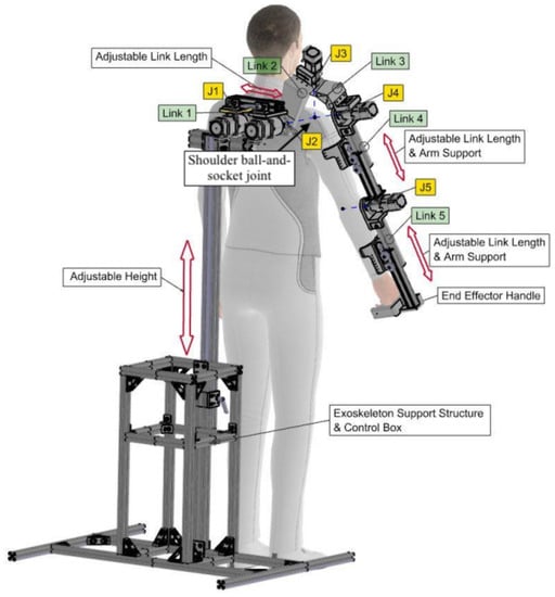
Figure 1.
Joint-based exoskeleton design [10].
The exoskeleton shoulder is modeled as a ball-and-socket joint where three revolute joints are serially linked together and their axes intersect at a single point as shown in Figure 1. The shoulder assembly was modeled as such so that the center-of-rotation (COR) of the exoskeleton shoulder aligns with that of the user’s glenohumeral joint. Moreover, the exoskeleton shoulder itself is composed of four motors that help drive the shoulder related motions. The last motor is located at the attachment point between link 4 and 5, which helps drive the elbow flexion-extension motion. This attachment point is known as the exoskeleton elbow joint, which is modeled as a 1-DOF revolute joint.
2.2. Task-Based Exoskeleton
The task-based exoskeleton is an over-constrained parallel mechanism that was developed to generate a desired limb trajectory–elbow flexion-extension–for upper limb rehabilitation [11]. In order to accomplish the 1-DOF motion, each link composing the exoskeleton has the same length as its opposing link.
The mechanism is composed of four links: the ground link, input link, coupler link, and output link; the end-effector is located at the coupler link. The fixed/ground link is represented as link 1 and the end-effector is represented as link 4, as shown in Figure 2. The mechanism is driven by a single motor that is located at the attachment point between link 1 and link 3. Finally, link 2 is considered the follower in the design or in other words, the output link. All joints composing the task-based mechanism are modeled as revolute joints, which allow the driven elbow flexion-extension motion.
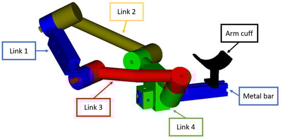
Figure 2.
Task-based exoskeleton design [11].
3. Methods
3.1. Modeling in OpenSim
The OpenSim software aided with the assessment of both exoskeleton designs [12]. The software offers a variety of tools such as Inverse Kinematics (IK), Body Kinematics (BK), and Muscle Analysis (MA) that allows for motion generation, obtaining information on position and orientation of each body composing the model, and obtaining muscle-related information, respectively. All tools mentioned were used during the assessment.
OpenSim’s Upper Extremity Dynamic Model was used to perform the assessment on both designs. The musculoskeletal model is composed of a total of 50 muscles and includes 15 DOFs which represents the shoulder, elbow, forearm, wrist, thumb, and index finger motions [13]. Within the model, the elbow joint rotates about a fixed axis that passes between the center of the trochlear sulcus and the center of the capitulum of the humerus [14]. Prior to the assessment, both exoskeletons were modeled within the existing musculoskeletal model.
3.1.1. Joint-Based Exoskeleton
In order to model the joint-based exoskeleton within OpenSim, all parts composing the design were incorporated and assembled within the Upper Extremity Dynamic Model. Before initiating the modeling of the exoskeleton within the existing musculoskeletal model, the geometry file of each part composing the exoskeleton were converted into a format accepted by OpenSim–.vtp, .stl, or .obj. After the new files were acquired, each part was incorporated into the Upper Extremity Dynamic Model script file as bodies.To incorporate the bodies to the model, the geometrical information of each body was acquired and added to the script file under the appropriate body. This included information regarding the joint frame geometry for each joint composing the exoskeleton design, each part’s location relative to its parent body from their respective origins, and the range of motion of the joints. Figure 3 demonstrates the method of determining the joint frame geometry for each joint. The geometrical information of each exoskeleton joint was gathered using the CATIA V5-3DX R2020 software.
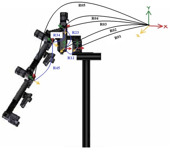
Figure 3.
Joint-based exoskeleton joint frame geometry.
First, each joint was converted into the form of the world frame in terms of orientation; the world frame used is the world frame of the existing musculoskeletal model. After each joint frame was in the correct orientation relative to the world frame, the orientation displacement between two consecutive joints was determined using Equation (1), where and are matrices of two consecutive joint frames and is the orientation displacement matrix between the two joint frames. For instance, in Figure 3, is the orientation displacement matrix between and . The Euler orientation of each joint was then determined in Matlab using Equation (2).
After the Euler orientation was gathered for each joint, a joint was created within the script file under the appropriate bodies. Two types of joints were used–CustomJoints and WeldJoints. A CustomJoint was used for joints that are able to rotate along the joint axes, while a WeldJoint was used for joints that are fixed and should not rotate. Once the joints were created, the Euler orientation information of each joint composing the exoskeleton was added to the script file of the model under its appropriate body. In addition, a range of motion was specified for each joint regarding its rotations and translations along the x, y, and z axes. Further adjustments were made to the body, if necessary, using the “transform” tool to translate and/or rotate the body with respects to its part frame. In addition, the location of each part frame was adjusted when necessary so that their origins were at their appropriate attachment point using the “position in body” tool. This tool was used to assemble the exoskeleton.
3.1.2. Task-Based Exoskeleton
Similar steps were performed to incorporate the task-based exoskeleton model onto the existing musculoskeletal model. Each part was incorporated as a body to the model and each body’s geometrical information was gathered and added to the model’s script file under the appropriate body. Figure 4 demonstrates the method of determining the joint frame geometry information for each joint.
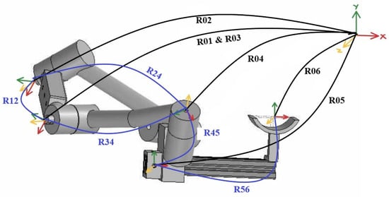
Figure 4.
Task-based exoskeleton joint frame geometry.
Similar to the joint-based exoskeleton, the orientation of each joint was altered to cohere with the world frame and then Equations (1) and (2) were used to determine the orientation displacement between two consecutive joints. The Euler orientation of each joint was then added under the appropriate body and joint within the model’s script file. The joints were characterized as WeldJoints or CustomJoints based on if the joint was fixed or had the ability to rotate respectively. The range of motion of the joints classified as a CustomJoint were then identified in the x, y, and z axes. Finally, additional adjustments to assemble the exoskeleton and adjust the bodies’ origins were made using the “position in parent body” and “transform” tools.
3.2. Simulating in OpenSim
The elbow flexion-extension motion was simulated within OpenSim to assess both exoskeletons on their alignment at the elbow joint. The trajectory of the motion was previously recorded using a motion capture system. The acquired trajectory was then used to create the elbow flexion-extension motion using the IK toolbox offered by OpenSim, which creates a motion file. A marker set was used to perform this task to dictate the location of the designated anatomical positions on the human model.
3.2.1. Joint-Based Exoskeleton
Once the exoskeleton was modeled and assembled within OpenSim, the elbow flexion-extension motion was simulated upon the human model using IK, previously recorded motion capture data, and a marker set. Although the motion was generated upon the human model, this motion was not yet prevalent on the joint-based exoskeleton model. The motion was generated on the exoskeleton by accessing the motion file obtained from performing IK and replicating the motion of the elbow joint throughout the elbow flexion-extension motion onto the respective exoskeleton joint—. Therefore, the joint was generated to vary from 44.079 to 125.634 for elbow flexion and vice versa for elbow extension. The exoskeleton’s initial position was then adjusted to correspond with the new initial posture of the human model.
3.2.2. Task-Based Exoskeleton
Once the model of the exoskeleton was fully assembled, the elbow flexion-extension motion was simulated upon the human model following the same steps as previously mentioned. However, replicating the elbow flexion-extension motion onto the task-based exoskeleton was far more complicated than doing it for the joint-based exoskeleton since the elbow joint does not have a corresponding task-based exoskeleton joint. Hence, more calculations were needed to successfully simulate the elbow flexion-extension motion upon the task-based exoskeleton. Similar to the joint-based exoskeleton simulation process, the motion file obtained from IK was used to incorporate the motion upon the exoskeleton.
First, the range of motion was specified for each link where link 2 varies from 21.190 to 10.588 for elbow flexion and vice versa for elbow extension, link 3 varies from 0 to −95.294 for elbow flexion and vice versa for elbow extension, and link 4 varies from 31.765 to 21.176 for elbow flexion and vice versa for elbow extension. It is important to notice that the duration of the motion is 4.750 s while the motion switches from elbow flexion to elbow extension at the 2.707 s mark. In addition, within the motion file, it is noted that the whole motion involves a total of 286 time intervals, while the 2.7 s mark is at the 163rd time interval. Therefore, to perform the elbow flexion motion, the difference between the final angle and initial angle was calculated for each link and divided by 163 since the task-based exoskeleton performs the task in a uniform velocity. As shown in Equation (3), is the angle value used for the number sequence where the difference between two consecutive values in the elbow flexion trajectory is , is the final angle that each link reaches at the end of the elbow flexion motion, and is the initial angle that each link is in prior to initiating the elbow flexion motion. For instance, for link 2, is 10.588 and is 21.190 hence, is −0.06504.
A similar process was used to generate the elbow extension motion. However, this time, Equation (4) was used where is the angle value used for the number sequence where the difference between two consecutive values in the elbow extension trajectory is , is the final angle that each link reaches at the end of the elbow extension motion, is the initial angle that each link is in prior to initiating the elbow extension motion, and 123 is the remaining amount of time intervals after the elbow flexion motion was performed—obtained by subtracting the amount of time intervals used for elbow flexion (163) from the total number of intervals used for the elbow flexion-extension motion (286). For instance, for link 2, is 21.190 and is 10.588 hence, is 0.08609.
3.3. Quantifying Misalignment at the Elbow Joint
Quantifying the misalignment present in each exoskeleton design will allow the comparison between the two designs when observing the effects that their misalignments have on the muscle tendon lengths of the main flexor and extensor muscles. Theoretically, if the misalignment is significant, it will cause the tendons to reach dangerous levels of variation. Nonetheless, the levels of variation in tendon length cannot be obtained without quantifying the misalignment of each design first and then applying the misalignment to the human model used.
3.3.1. Joint-Based Exoskeleton
Once the human model and joint-based exoskeleton were coordinately performing the elbow flexion-extension task, the BK toolbox was used to obtain information on the location of each body’s origin throughout the generated motion. The origin position coordinates of the ulna and link 5 were then compared in the frontal, vertical, and sagittal axes as well as their orientations in elbow varus-valgus, elbow supination-pronation, and elbow flexion-extension (, , and ) throughout the generated motion; Figure 5A demonstrates this comparison during elbow flexion and Figure 5B during elbow extension, where the axes of the ulna frame, link 5 frame, and world frame are represented by , , and , respectively. In addition, the position displacement values that we identify are with respect to the world frame, the orientation displacement values are with respect to the ulna frame, and are the axes of rotation of , , and , respectively.
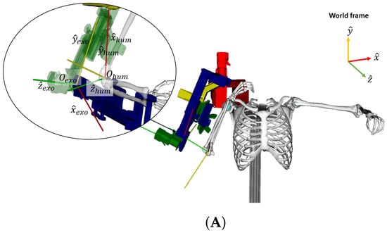
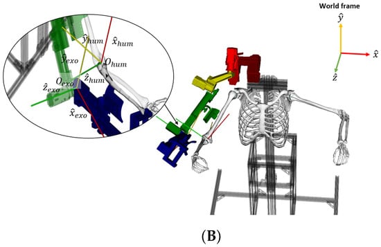
Figure 5.
Joint-based exoskeleton’s elbow joint and human elbow joint axis alignment during elbow (A) flexion and (B) extension.
The position displacements between the two bodies with respect to the world frame were calculated using Equation (5), where is the position of the human elbow joint with respect to time, is the position of the exoskeleton elbow joint with respect to time, is the initial displacement, and is the overall position displacement with respect to time.
In addition, the orientation displacement between the two bodies’ frames were also calculated using Equation (6), where is the orientation of the human elbow joint with respect to time, is the orientation of the exoskeleton elbow joint with respect to time, and is the overall orientation displacement between the two bodies with respect to time. The position and orientation displacement results are shown in Figure 6.
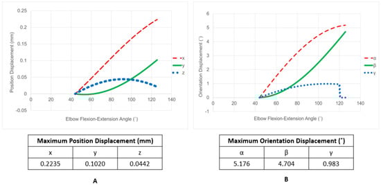
Figure 6.
Joint-based exoskeleton (A) position and (B) orientation displacements.
A new human model was created where the ulna’s origin position was translated and rotated using the maximum position and orientation displacement values identified in the and , , and directions shown in Figure 6. This new model is referred to as the joint-based misaligned human model and the initial human model is referred to as the original human model.
3.3.2. Task-Based Exoskeleton
Since the task-based exoskeleton design does not have a part and/or joint that corresponds to the human ulna and/or elbow joint, a different approach was taken to assess this exoskeleton design.
The varus and valgus stress tests are used in order to identify any tears and injuries in these ligaments [15,16,17,18]. A moving valgus stress test was performed on twenty-one subjects, where the elbow flexion-extension motion was generated while a valgus torque was being applied [18]. It was found that the subjects experienced pain when the elbow was flexed and extended between 70 and 120, where a maximum pain occurred when the elbow was flexed 90. Since the task-based design is not able to provide support at the elbow throughout the generation of the rehabilitation task, it is necessary to assess the design on the varus-valgus angle that it causes upon the user’s elbow joint; a large angle could cause tears upon corresponding ligaments as well as pain at the elbow joint. In order to perform this assessment, a set of dummy bodies were added to the human-exoskeleton model and used to track and compare the positions of the exoskeleton’s arm cuff and its attachment point at the ulna during elbow flexion and extension using Equation (5), as shown in Figure 7. The axes of the frame composing the dummy body placed at the exoskeleton arm cuff, the dummy body placed at the ulna, and world frame are represented by , , and , respectively. When elbow flexion-extension was successfully generated upon the task-based exoskeleton and human model, the musculoskeletal model was prepared to undergo BK to access information on each body’s position and orientation throughout the generated motion. The positions of the exoskeleton arm cuff and ulna at their attachment points were obtained and compared in order to determine the varus-valgus angle using the arc length formula shown in Figure 8, where is a vector of the maximum position displacement of the exoskeleton arm cuff and ulna, r is the distance between the elbow joint and arm cuff-ulna attachment point, and is the angle vector for elbow varus-valgus, elbow supination-pronation, and elbow flexion-extension.
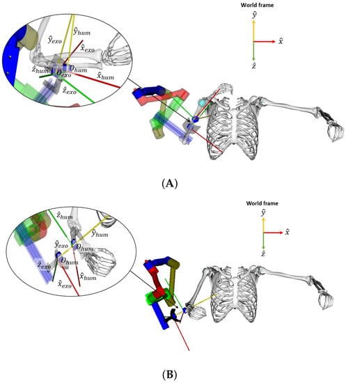
Figure 7.
Demonstration of exoskeleton arm cuff and ulna attachment positions during (A) elbow flexion and (B) elbow extension.
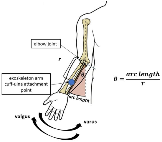
Figure 8.
Arc length formula used to find varus-valgus angle.
The position displacement between the exoskeleton arm cuff and the ulna at their attachment point are shown in Figure 9. For the human model used, elbow varus-valgus occurs in the direction. However, the position displacement values obtained from BK are relative to the world frame. Since the world frame and the ulna frame are not equivalent in direction, those displacement values were translated and rotated to correspond to the frame of the ulna—Table 1 demonstrates the maximum position displacement values used as the arc length vector in the arc length formula shown in Figure 8.
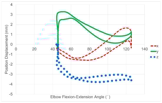
Figure 9.
Position displacements between the exoskeleton arm cuff and ulna at their attachment points.

Table 1.
Maximum Position Displacements from Task-Based Exoskeleton.
The distance between the elbow joint and arm cuff-ulna attachment point at the forearm were also obtained using the BK files and Equation (7), where is the position of the arm cuff-ulna attachment point at the forearm, is the position of the elbow joint, are the coordinates of , and are the coordinates of . This distance represents r in the arc length formula.
Finally, using the arc length formula from Figure 8, it was found that the varus-valgus angle caused by the exoskeleton is −7.122. The angles obtained for elbow supination-pronation and flexion-extension were neglected for the purpose of this study since those two motions are safe and common motions occurring at the elbow joint. A new human model was developed where the ulna was rotated using the varus-valgus angle found. This new model is referred to as the task-based misaligned human model.
4. Results
Muscle Tendon Length Variations from Misalignment
Three simulations were performed for the elbow flexion-extension task using the original model, the joint-based misaligned model, and the task-based misaligned model. The MA tool was used on all three simulations to obtain information on muscle tendon length throughout the motion. The tendon lengths obtained from the joint-based and task-based misaligned models were then compared to the lengths obtained from the original model. Theoretically, if the misaligned models demonstrate significant variations in muscle tendon length, it would indicate that the exoskeleton presents a misalignment that could be detrimental to the users. The muscle groups observed for this assessment include the main elbow flexor (biceps brachii, brachialis, and brachioradialis) and extensor (triceps brachii and anconeus) muscles.
The results of the assessment are shown in Figure 10 for the flexor and extensor muscles. The results obtained from the joint-based misaligned model are labeled as “with joint-based exoskeleton”, the results obtained from the task-based misaligned model are labeled as “with task-based exoskeleton”, and the results obtained from the original human model are labeled as “without exoskeleton”. As demonstrated in Figure 10A–D, all flexor muscles of the joint-based model demonstrated minor variations in tendon length when comparing the results of the original and misaligned human models. The biceps short, biceps long, brachialis, and brachioradialis demonstrated a maximum variation in tendon length of 0.1126 mm, 0.1126 mm, 0.0835 mm, and 0.1580 mm respectively. Similarly, the same muscles demonstrated a maximum variation of 0.0779 mm, 0.0779 mm, 0.0495 mm, and 0.2893 mm, respectively, from the task-based misalignment.
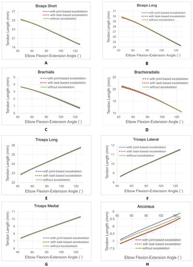
Figure 10.
Muscle tendon length variations of the main flexor and extensor muscles—(A) biceps short, (B) biceps long, (C) brachialis, (D) brachioradialis, (E) triceps long, (F) triceps lateral, (G) triceps medial, and (H) anconeus.
In addition, it is demonstrated in Figure 10E–H that all extensor muscles of the joint-based misaligned model also presented minor variations in tendon length when comparing its results to those of the original model. The triceps long, triceps medial, triceps lateral, and anconeus demonstrated a maximum variation in tendon length of 0.0692 mm, 0.0692 mm, 0.0692 mm, and 0.3581 mm respectively. Similarly, the same muscles demonstrated a maximum variation of 0.0214 mm, 0.0214 mm, 0.0214 mm, and 0.2082 mm, respectively, from the task-based misalignment.
To further assess the exoskeletons, it is important to note that a muscle tendon has a limit to its length variation. On average, a muscle tendon can variate to a maximum of 10% of its healthy length during motion prior to becoming injured [19]. A tendon’s length typically varies throughout a generated range of motion. However, a specific tendon length can cause different effects at a lower joint-angle vs. a higher joint-angle (i.e., for certain tendons, a higher tendon length at a lower joint-angle could cause injury, whereas no injury could result from the same tendon length occurring at a higher joint-angle–vice versa). The values were found for the muscles observed as shown in column B and D of Table 2. The healthy tendon length values were identified depending on the angle that the maximum variations observed occurred at throughout the generated motion—as shown in Figure 10, all maximum variations occurred at either the 45 or 125 joint-angles of the elbow flexion-extension motion.
Table 2.
Muscle Tendon Length Variations from Joint-Based and Task-Based Misalignments—(A) Healthy Tendon Length @ 45(mm), (B) 10% Values @ 45 (mm), (C) Healthy Tendon Length @ 125(mm), (D) 10% Values @ 125 (mm), (E) Joint-Based Tendon Length Maximum Variations (mm), (F) Joint-Based Percentile Tendon Length Variation (%), (G) Task-Based Tendon Length Maximum Variations (mm), and (H) Task-Based Percentile Tendon Length Variation (%).
5. Discussion
Based on the limit values found, all muscles observed satisfied their length variation limits when the joint-based and task-based exoskeleton misalignments were applied as shown in Table 2. Overall, the task-based exoskeleton performed slightly better than the joint-based exoskeleton when comparing the variations in tendon length caused by their misalignment. As shown in Table 2, the variations in tendon length of all muscles, except the brachioradialis, were slightly lower for the task-based. However, it can also be seen that the variation in tendon length at the brachioradialis favored the joint-based exoskeleton. The highest level of variation occurred at the anconeus when both exoskeleton misalignment were applied. Nonetheless, no variation was close to being 10% of the tendon’s healthy length at the observed joint-angles since all percentile variations were below 7%, as shown in Table 2. Hence, although the assessment favored the task-based exoskeleton, it can be concluded that both exoskeletons do not present misalignment levels that lead to significant variations in tendon length.
The proposed assessment methods for human-exoskeleton alignment can be used as an aid during the exoskeleton design process to motivate improvement in exoskeleton designs and their alignment to the human body. The assessment methods could also be used to identify safe ranges of motion during elbow flexion-extension and limit exoskeleton movement to those safe ranges, which could avoid dangerous levels of human-exoskeleton misalignment and tendon length variations. In addition, an exoskeleton can be tested on its alignment upon different individuals with varying anatomical dimensions to assess an exoskeleton’s ability to account for subject variation by using the scale tool in OpenSim and then performing the presented methods.
In this paper, the alignment of the exoskeleton is assessed using model-based simulations in OpenSim, a software widely used in replicating the human body’s range of motion and musculoskeletal system. While OpenSim provides reliable results, it is beneficial to validate these findings using experimental protocols that incorporate motion capture analysis and variation in electromyography (EMG) signals of targeted muscles. By comparing the performance of both exoskeletons with and without the exoskeleton, the metrics can be quantified based on the variation in sEMG signals during the execution of the same task. Similarly, by incorporating motion capture analysis, which tracks the movement of the body and joints, along with sEMG signal analysis, the assessment becomes more holistic, capturing both kinematic and muscular aspects. This combined approach enhances the reliability and validity of the assessment, providing a more comprehensive understanding of the exoskeleton’s impact on human performance and safety.
6. Conclusions
This study presented an assessment on a joint-based and task-based exoskeletons for upper limb rehabilitation using OpenSim. The assessments were focused on quantifying the misalignment and the effects on the muscle tendon lengths within the main flexor and extensor muscles during elbow flexion-extension. The results demonstrated that although both exoskeletons presented misalignment in the x, y, and z axes and , , and directions when compared to the targeted human limb, they had little to no effects on the muscle tendon length of the main flexor and extensor muscles. All percentile variations in tendon length were lower than 7% for both exoskeletons when the maximum percentile variation before becoming injured is 10%; the anconeus presented the highest percentile variation of 6.782% and 2.987% from the joint and task-based misalignment, respectively and the brachialis for the task-based misalignment with a percentile variation of 6.875%. Hence, indicating that the joint-based and task-based designs are safe to use when the elbow flexion-extension is generated from 45 to 125. Nonetheless, the results obtained from the assessment method can be an aid to further improve the exoskeleton designs on their alignment and to identify and limit safe ranges of motion during elbow flexion-extension which could avoid dangerous levels of tendon length variations. The assessment method did not account for the weight of the devices, which could potentially cause an effect on their alignment to the human body, therefore, future work would consider this factor during the assessment process.
Author Contributions
Conceptualization, C.R., P.D. and Y.Y.; methodology, C.R. and P.D.; software, C.R. and P.D.; data curation, C.R.; investigation, C.R., P.D. and Y.Y.; validation, C.R., P.D., N.A.H. and Y.Y.; formal analysis, C.R. and P.D.; resources, Y.Y. and N.A.H.; writing—original draft preparation, C.R.; writing—review and editing, P.D., N.A.H. and Y.Y.; supervision, Y.Y.; funding acquisition, Y.Y. and N.A.H. All authors have read and agreed to the published version of the manuscript.
Funding
This work was supported by the National Science Foundation under grant no. CBET-1915872. The content is solely the authors’ responsibility.
Data Availability Statement
Data is available upon request.
Conflicts of Interest
The authors declare no conflict of interest.
Abbreviations
The following abbreviations are used in this manuscript:
| IMU | Internal Measurement Unit |
| DOF | Degrees of Freedom |
| COR | Center of Rotation |
| IK | Inverse Kinematics |
| BK | Body Kinematics |
| MA | Muscle Analysis |
| UCL | Ulnar Collateral Ligament |
| BIClong | Biceps Long |
| BICshort | Biceps Short |
| BRA | Brachialis |
| BRD | Brachioradialis |
| TRIlong | Triceps Long |
| TRIlat | Triceps Lateral |
| TRImed | Triceps Medial |
| ANC | Anconeus |
References
- Meng, Q.; Xiang, S.; Yu, H. Soft robotic hand exoskeleton systems: Review and challenges surrounding the technology. In Proceedings of the 2017 2nd International Conference on Electrical, Automation and Mechanical Engineering (EAME 2017), Shanghai, China, 23–24 April 2017; Atlantis Press: Amsterdam, The Netherlands, 2017; pp. 186–190. [Google Scholar]
- Krichevets, A.N.; Sirotkina, E.; Yevsevicheva, I.; Zeldin, L. Computer games as a means of movement rehabilitation. Disabil. Rehabil. 1995, 17, 100–105. [Google Scholar] [CrossRef] [PubMed]
- Delgado, P.; Alekhya, S.; Majidirad, A.; Hakansson, N.A.; Desai, J.; Yihun, Y. Shoulder Kinematics Assessment towards Exoskeleton Development. Appl. Sci. 2020, 10, 6336. [Google Scholar] [CrossRef]
- Karavas, N.C.; Tsagarakis, N.G.; Caldwell, D.G. Design, modeling and control of a series elastic actuator for an assistive knee exoskeleton. In Proceedings of the 2012 4th IEEE RAS & EMBS International Conference on Biomedical Robotics and Biomechatronics (BioRob), Rome, Italy, 24–27 June 2012; IEEE: Piscataway Township, NJ, USA, 2012; pp. 1813–1819. [Google Scholar]
- MajidiRad, A.; Yihun, Y.; Desai, J.; Hakansson, N.A. Simulation of Exoskeleton Alignment and its Effect on the Knee Extensor and Flexor Muscles. In Proceedings of the 2019 41st Annual International Conference of the IEEE Engineering in Medicine and Biology Society (EMBC), Berlin, Germany, 23–27 July 2019; IEEE: Piscataway Township, NJ, USA, 2019; pp. 4093–4096. [Google Scholar]
- Zeiaee, A.; Soltani-Zarrin, R.; Langari, R.; Tafreshi, R. Design and kinematic analysis of a novel upper limb exoskeleton for rehabilitation of stroke patients. In Proceedings of the 2017 International Conference on Rehabilitation Robotics (ICORR), London, UK, 17–20 July 2017; IEEE: Piscataway Township, NJ, USA, 2017; pp. 759–764. [Google Scholar]
- Sposito, M.; Di Natali, C.; Toxiri, S.; Caldwell, D.G.; De Momi, E.; Ortiz, J. Exoskeleton kinematic design robustness: An assessment method to account for human variability. Wearable Technol. 2020, 1, e7. [Google Scholar] [CrossRef]
- De Kruif, B.J.; Schmidhauser, E.; Stadler, K.S.; O’Sullivan, L.W. Simulation architecture for modelling interaction between user and elbow-articulated exoskeleton. J. Bionic Eng. 2017, 14, 706–715. [Google Scholar] [CrossRef]
- Delgado, P.; Rincon, C.; Yihun, Y. Human-Exoskeleton Joint Coordination Assessment: A Case Study on the Shoulder and Elbow Joints. J. Bionic Eng. 2022, 16, 1712–1721. [Google Scholar] [CrossRef]
- Attampola Arachchige Don, T. Development of an Adaptive Exoskeleton for Upper Arm Rehabilitaion. Ph.D. Thesis, Wichita State University, Wichita, KS, USA, 2021. [Google Scholar]
- Delgado, P.; Arachchige Don, T.A.; Gomez, J.; Miranda, V.; Yihun, Y. Design of Bio-Exoskeleton for Elbow Rehabilitation. In Frontiers in Biomedical Devices; American Society of Mechanical Engineers: New York, NY, USA, 2021; Volume 84812, p. V001T10A002. [Google Scholar]
- Delp, S.L.; Anderson, F.C.; Arnold, A.S.; Loan, P.; Habib, A.; John, C.T.; Guendelman, E.; Thelen, D.G. OpenSim: Open-source software to create and analyze dynamic simulations of movement. IEEE Trans. Biomed. Eng. 2007, 54, 1940–1950. [Google Scholar] [CrossRef] [PubMed]
- Holzbaur, K.R.; Murray, W.M.; Delp, S.L. A model of the upper extremity for simulating musculoskeletal surgery and analyzing neuromuscular control. Ann. Biomed. Eng. 2005, 33, 829–840. [Google Scholar] [CrossRef] [PubMed]
- London, J.T. Kinematics of the elbow. J. Bone Jt. Surg. Am. Vol. 1981, 63, 529–535. [Google Scholar] [CrossRef]
- Solitro, G.F.; Fattori, R.; Smidt, K.; Nguyen, C.; Morandi, M.M.; Barton, R.S. Role of the transverse ligament of the ulnar collateral ligament of the elbow: A biomechanical study. JSES Int. 2021, 5, 549–553. [Google Scholar] [CrossRef] [PubMed]
- Frangiamore, S.J.; Bigart, K.; Nagle, T.; Colbrunn, R.; Millis, A.; Schickendantz, M.S. Biomechanical analysis of elbow medial ulnar collateral ligament tear location and its effect on rotational stability. J. Shoulder Elb. Surg. 2018, 27, 2068–2076. [Google Scholar] [CrossRef] [PubMed]
- Ruland, R.T.; Hogan, C.J.; Randall, C.J.; Richards, A.; Belkoff, S.M. Biomechanical comparison of ulnar collateral ligament reconstruction techniques. Am. J. Sports Med. 2008, 36, 1565–1570. [Google Scholar] [CrossRef] [PubMed]
- O’Driscoll, S.W.; Lawton, R.L.; Smith, A.M. The “moving valgus stress test” for medial collateral ligament tears of the elbow. Am. J. Sports Med. 2005, 33, 231–239. [Google Scholar] [CrossRef] [PubMed]
- Woo, S.L.Y.; Debski, R.E.; Zeminski, J.; Abramowitch, S.D.; Chan Saw, S.S.; Fenwick, J.A. Injury and repair of ligaments and tendons. Annu. Rev. Biomed. Eng. 2000, 2, 83–118. [Google Scholar] [CrossRef] [PubMed]


Disclaimer/Publisher’s Note: The statements, opinions and data contained in all publications are solely those of the individual author(s) and contributor(s) and not of MDPI and/or the editor(s). MDPI and/or the editor(s) disclaim responsibility for any injury to people or property resulting from any ideas, methods, instructions or products referred to in the content. |
© 2023 by the authors. Licensee MDPI, Basel, Switzerland. This article is an open access article distributed under the terms and conditions of the Creative Commons Attribution (CC BY) license (https://creativecommons.org/licenses/by/4.0/).