Abstract
In this paper, we propose a hybrid beamforming architecture with constant phase shifters (CPSs) for uplink cell-free millimetre-wave (mm-Wave) massive multiple-input multiple-output (MIMO) systems based on exploiting antenna selection to reduce power consumption. However, current antenna selection techniques are applied for conventional massive MIMO, not cell-free massive MIMO systems. Therefore, the enormous computational complexity of these techniques to optimally select antennas for cell-free massive MIMO networks is caused by numerous randomly distributed access points (APs) in the service area and their large antennas. The architecture proposed in this work solves this issue by employing a low-complexity matching technique to obtain the optimal number of antennas, chosen based on channel magnitude and by switching off antennas that contribute more to interference power than to desired signal power for each radio frequency (RF) chain at each AP, instead of assuming all RF chains at each AP have the same number of selected antennas. Therefore, an assignment optimization problem based on a bipartite graph is formulated for cell-free mm-Wave massive MIMO system uplinks. Then, the Hungarian method is proposed to solve this problem due to its ability to solve this assignment problem in a polynomial time. Simulated results show that, despite several APs and antennas, the proposed matching approach is more energy-efficient and has lower computational complexity than state-of-the-art schemes.
1. Introduction
Fifth-generation (5G) wireless communication can now operate in the millimetre-wave (mm-Wave) frequency range 2 (FR2), which spans from 24 GHz to about 70 GHz [] and will almost certainly play a vital role in future generations such as sixth-generation (6G) systems []. However, the mm-Wave approach suffers from significant path loss in propagation from a communication point of view. This issue can be solved by effectively implementing mm-Wave technology with massive MIMO systems employing large antenna arrays with convenient beamforming techniques to mitigate the effect of path loss [,]. Furthermore, cell-free systems are accomplished by deploying many geographically distributed access points (APs) over the coverage area without cell boundaries []. These APs are linked to a central processing unit (CPU) via high-speed fibre or wireless backhaul/fronthaul links to simultaneously serve user equipment (UE) and time-frequency resources []. From these aspects, cell-free massive MIMO systems can provide a good quality of service (QoS) to all UEs in the coverage area compared to distributed massive MIMO systems [,].
Power consumption and hardware cost of mm-Wave systems are significantly higher when completing the entire process in the digital domain with a large number of antennas. A more convenient solution is to adopt a hybrid analog/digital design as a more cost-effective option []. A large number of antennas are connected to a small number of radio frequency (RF) chains that perform analog-to-digital conversion via an analog front-end (implemented using phase shifters) [,]. The hybrid analog/digital approach has two main schemes: fully connected and partially connected. The fully connected way is when each RF chain is connected to all of the antennas, and the partially connected scheme is when each RF chain is connected to some of the antennas [,,,]. The authors in [] proposed the hybrid analog/digital structure by employing constant phase shifters (CPSs) instead of using variable phase shifters (VPSs) due to huge power consumption and hardware complexity in the case of the fully connected scheme with a large number of antennas. They also utilized switches in the design of the analog beamforming. Thus, their proposed method achieved better energy efficiency and a slight loss in spectral efficiency using low-power CPSs. Additionally, the authors in [] used the same structure as in [] and maximized the signal-to-interference-plus-noise ratio (SINR) by presenting novel algorithms based on quasi-orthogonal combining. However, depending on channel conditions, when signals received at many antennas are aggregated at the RF chain, a subset of antennas may contribute more to interference than to the desired signal power, resulting in SINR loss. To enhance energy efficiency, a zero-forcing precoding technique was presented in [] with a low complexity power control scheme for cell-free massive MIMO systems. The performance of cell-free mm-Wave massive MIMO systems was studied using a hybrid beamforming technique with limited fronthaul capacity, in which precoders and combiners were created using an Eigen beamforming scheme []. The authors in [] proposed adaptive RF chain activation (ARFA) to reduce power consumption in uplink cell-free mm-Wave massive MIMO systems, where the fully connected hybrid analog/digital approach is individually created at each AP using known channel state information (CSI). However, the phase shifters in this technique are huge due to the vast number of antennas at each AP, resulting in high hardware implementation costs and power consumption. A hybrid beamforming technique with fixed phase shifters based on an alternating minimization algorithm for the uplink cell-free massive MIMO systems was presented in []. They also employed fixed phase shifters with dynamic cascade switches at each AP to avoid the performance loss caused by erroneous fluctuation of the adaptive fixed number of phase shifters with channel conditions. Another approach to minimize power consumption and hardware complexity is the antenna selection that can be applied in cell-free massive MIMO systems. Still, this is an undesirable solution due to the loss of the antenna gains, which indicates that the signals transmitted or received by the antennas in a specific direction suffer from weakness. Then, the power of the transmitted or received antennas is lower than that of hypothetical ideal antennas in a similar situation, as well as having insufficient data rates []. The authors of [] proposed an antenna selection scheme in cell-free massive MIMO systems to assign each UE to a subset of APs with the best channel status. However, they proposed a single antenna for each UE without considering when the AP is equipped with a large number of antennas and the hybrid analog/digital approach. Furthermore, because a massive MIMO system can use a large number of receiving antennas, the number of switches necessary to link the antennas to the RF chains is large, and these switches can consume a large amount of power. This problem is overcome in [] by introducing a new hybrid beamforming architecture for conventional massive MIMO systems whereby each RF chain is connected to a subset of antennas that contribute more to the desired power rather than the interference power. Further, they introduced three low-complexity algorithms compared with the exhaustive search approach to perform the selection process for the switches at the base station.
In this work, we investigate the flexibility of including or excluding the subset of antennas in the signal combining design by extending the proposed algorithms in [] from conventional multi-user mm-Wave MIMO systems to cell-free mm-Wave massive MIMO systems, especially when there are a large number of APs. Each AP has a large number of antennas. Then, we propose a novel antenna selection strategy based on the Hungarian matching method, which provides considerable power reduction while maintaining the system’s spectral efficiency. Furthermore, we propose the channel quality for each AP to assign each RF chain to its suitable set of selected antennas. Based on that, the proposed matching scheme can improve system performance and provide a tradeoff between spectral and energy efficiencies and computational complexity. In addition, to the best of our knowledge, no other works consider the Hungarian matching algorithm [] in the hybrid analog/digital approach for cell-free massive MIMO systems. The main contributions of this paper are summarized as follows:
- We extend the work in [], which has been proposed for conventional multi-user massive MIMO, to cell-free massive MIMO systems. We adapt the three low-complexity algorithms proposed in [] to perform the selection process for the switches at the APs.
- For all APs in the cell-free network, we propose an assignment optimization problem to accomplish matching between RF chains and several sets of selected antennas based on channel conditions. Then, we propose the Hungarian method to solve this optimization problem based on maximum weight matching in order to maximize energy efficiency. In contrast to [], instead of assuming that all RF chains in the AP have the same fixed active switches, we exploit the advantages of the matching theory based on the Hungarian algorithm to assign each RF chain at each AP in the cell-free network to the optimal number of activated switches depending on AP channel condition in order to maximize energy efficiency.
- Simulation results demonstrate the performance of the proposed antenna selection strategies under an extensive set of cell-free mm-wave massive MIMO scenarios. In particular, the number of APs, the number of antennas, and the number of users in the network are analysed in terms of energy efficiency. In addition, computational complexity of the proposed algorithms is studied in this work.
Notation: The row and column entry of matrix A is expressed as . In addition, , , and are used to denote the conjugate transpose, transpose, and inverse of matrix A, respectively. The magnitude of scalar is denoted by , and gives the element-wise multiplication of matrices A and B; represents the matrix with all zero entries; denotes the expectation operator; finally, shows the Euclidian norm of vector a.
2. System Model
We consider the uplink of a cell-free mm-Wave massive MIMO system, where M APs and K single-antenna UEs are randomly distributed in the coverage area. Fronthaul links are also utilized to connect the APs to the CPU, with each AP having receive antennas and RF chains as shown in Figure 1. For simplicity, we assume that each AP utilizes exactly (K = N) available RF chains to jointly serve K UEs, as in [,]. The received signal at the AP is distributed to multiple RF chains via a power splitter. In addition, a network of switches and CPSs are denoted by and CPSs, respectively. can be used to connect RF chain to out of antennas at AP. A power combiner before the RF chain combines the signals of . Each antenna can be connected to the CPSs when the switch is activated.
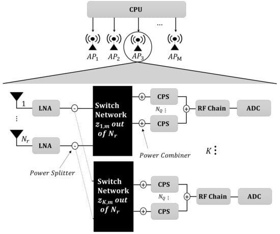
Figure 1.
Hybrid beamforming structure for each AP in uplink cell-free massive MIMO systems with CPSs connected to RF chains via switch network.
The CPU coordinates communication between the M APs and the K UEs utilizing a half-duplex time division duplexing (TDD) protocol in which each frame is divided into three main phases: uplink training, uplink data transmission, and downlink data transmission. In this work, we focus on the uplink cell-free mm-Wave massive MIMO system, and then all UEs transmit their pilot signals to the APs in the coverage area during the uplink training phase, allowing the APs to estimate the channels to each UE. The signals transmitted by the UEs in the uplink data transmission phase are subsequently detected using channel estimations. The length of the uplink training, represented by , should not exceed the channel’s coherence time/bandwidth interval, denoted by .
2.1. Channel Model
A narrowband block-fading channel model is adopted as the propagation environment between transmitters and receivers [,,,], which is known as geometric Saleh–Valenzuela channel model, and it is considered a typical channel model for uplink cell-free mm-Wave massive MIMO systems. The channel between the AP and UE is expressed as
where denotes antenna gain, and represents the pathloss between the AP and UE, which can be expressed from [,,] as
where is the reference distance, which is equal to one, is the wavelength, represents the distance between the AP and UE, the average pathloss exponent over the distance is represented by , and gives the shadow fading component with zero mean Gaussian random variable and standard deviation. Moreover, represents the number of propagation paths, the complex small scale fading gain is denoted by for all the APs and UEs in the service area, and is known as the azimuth angle of arrival (AoA) for each channel path. Each AP is assumed to be equipped with a uniform linear array (ULA), and this structure of the antenna array is utilized to obtain the receive array response vector at the AP, where is given by
where denotes antenna spacing of half of a wavelength []. Finally, let us consider and . Then, can be expressed as []
Thus, . In addition, the channel matrix between K UEs and the AP is , and the total channel between K UEs and all APs in the coverage area is defined as .
2.2. Analog Combining Design
The analog combining for each AP is based on CPSs and switches. Therefore, is given as
where denotes an array of CPSs for AP, while represents the switching network between the RF chain and at AP. Thus, the switching matrix for all K RF chains can be expressed as . The first constraint of the switching network that should be satisfied for RF chain inside AP [] is expressed as where symbolizes the receive antenna index at each AP, while CPSs index. The second constraint restricts each antenna on each RF chain to be connected at most to one CPS. Therefore, this restriction can be presented as Thus, the main objective of using the previous constraints in the design of is to easily exclude the antennas that contribute more to interference than to desired signal power, and their corresponding entries in become zeros. Furthermore, the for each RF chain in AP is shown as
2.3. Uplink Channel Estimation
The channel can be estimated at the APs when K UEs simultaneously start to transmit their pilot sequences of . The received pilot sequence at AP from K UEs, is expressed by
where denotes the transmission power of each pilot symbol sent by UE, gives pilot signal assigned to UE with , and is known as a matrix of independent identically distributed (i.i.d.) received noise samples, with each entry distributed as , in which is the noise power that can be computed as , where is the system bandwidth, and is the noise figure. It is worth noting that the vast majority of practical scenarios hold ; hence, several UEs are allocated to a given pilot sequence. That leads to the pilot contamination phenomenon [,]. Therefore, this work focuses on the case of . Based on , the AP can estimate the channel . Then, is the projection of onto , which is given as
Thus, the minimum mean square error (MMSE) is utilized to obtain the estimated channel under the assumption of the knowledge of , which is the correlation matrix for all UEs is available at AP []. For the MMSE estimation technique, we assume that the signals received at all of the AP’s antennas are available. As a result, the low-complexity MMSE estimator can be used to estimate the full channel state information (CSI) associated with all antennas. There is also a compressed sensing-based technique, as given in [], that can be used to extract the entire CSI in the situation of sparse channels and very slow fading; however, this approach is highly complex, especially in cell-free massive MIMO systems. Thus, can be derived as []
As a consequence, the total estimated channels between APs and K UEs is given as and . The next section explains how to employ the estimated channels and for the hybrid combining design in uplink data transmission.
2.4. Uplink Data Transmission
The symbol sent from the UE to all APs is symbolized by , and it can be detected by applying hybrid beamforming to the received signal at AP. Then, the received signal is expressed as
where is the average transmit power from all UEs, and represents the transmitted symbol by UE, and thus with . In addition, is a vector of the noise, while the hybrid analog/digital combining is , where denotes the digital combining vector for at AP, and is the analog combining matrix at AP. Note that the first term in (10) represents the received desired signal at AP, the second term describes the interference that happened due to utilizing the imperfect CSI, and the last term is the additive noise. In addition, the sum of the second and third terms is considered to be the interference plus noise, which is also known as effective noise. These two terms are uncorrelated. Moreover, the uncorrelated Gaussian noise is the worst case of the capacity. Furthermore, the received signal at each AP is forwarded to the CPU, and it is simultaneously processed using . The can be obtained by the MMSE beamforming scheme, which uses the effective channel [,]. Specifically, the is expressed as
where is the column of . There are two main stages to obtain , as mentioned in []. The first stage is to consider all switches in the active state, and the switching matrices corresponding to and are symbolized by and , respectively, with the same matrix sizes. As a consequence, the previously mentioned constraints are modified for each AP as and Thus, denotes the analog combiner that has non-zero elements due to the active states for all switches at AP. Euclidean distance is adopted to design the switching matrix . We also utilize QR decomposition to express in which and are orthogonal and right-triangular matrices, respectively. In addition, CPSs with their phase of the channel coefficient of antenna in each AP from corresponding to can be selected by the antenna’s switch in based on the shortest Euclidean distance. Thus, can be obtained by
where is the index of the selected CPSs, which is given by
where . Thus, the antenna switch that corresponds to is in an active state. The next stage considers a strategy to convert , which can be generated in the previous stage by considering all antennas for each AP as active, to which describes the selected antennas for each RF chain in each AP. Therefore, we consider , which is a binary matrix with size . The main aim for considering this matrix is to describe the state for each antenna at AP depending on if it is connected to RF chain or not, whereas ones denote the selected antennas, while deactivated antennas are depicted as zeroes in . Additionally, if antenna at AP is not connected to RF chain, that does not mean this antenna will not be connected for other RF chains. Thus, is generated by element-wise multiplication of each column vector of by each column , where as expressed below
Consequently, is converted to as follows
Thus, can be obtained with the help of the obtained optimal [].
The uplink spectral efficiency (SE) can be obtained based on similar analysis techniques, such as [,,,,]. The quickly fading random variables in complex numbers are independent, and they characterize the propagation model between UEs and APs. Cell-free massive MIMO systems with perfect CSI have a known capacity in some cases [], while the ergodic capacity is unknown in the case of imperfect CSI. However, the SE can be analysed by using standard-capacity lower bounds in this system [,]. Thus, the uplink spectral efficiency for AP (), which is measured in bits per second per Hertz, is obtained as follows
where denotes the effective instantaneous signal-to-interference-plus-noise ratio, which can be given as [,]
Therefore, the total uplink SE for all APs is expressed as
3. Problem Formulation and Proposed Solution
The problem formulated in [,] is NP-hard to obtain the optimal number of selected antennas for each RF chain. Therefore, when there are a large number of APs in the cell-free network, and each AP is equipped with a large number of , this will lead to remarkably high computational complexity to determine the optimally selected antennas using an exhaustive search method across . Additionally, the findings in [] indicate that using channel quality to switch on antennas that have a large channel magnitude can overcome the quasi-coherent combining algorithm for fixed CPSs (FCPSs) [] when the selected number of antennas for each RF chain is of antennas; further, similar performance compared with [] is achieved when of the selected antennas are utilized. Based on these findings, it is reasonable to conclude that excluding a particular number of antennas from can enhance , implying that these antennas contribute more to interference signal power than the desired signal power. In addition, these results motivated us to put forth the following question: How can we translate the optimization problem formulated in [,] from an NP-hard problem to an assignment problem to find the optimal number of selected antennas for each RF chain at each AP to enhance EE without a significant loss in SE based on the channel quality utilizing a low-computational complexity approach in an uplink cell-free mm-Wave MIMO network?
3.1. Problem Formulation
To answer the aforementioned question, we propose matching to assign each RF chain at AP to its suitable number of selected antennas instead of assuming a single predefined value of active antennas as mentioned in []. Furthermore, we consider half of the RF chains at each AP have selected antennas exceeding of the total number of antennas based on channel condition. On the other hand, each of the remaining RF chains might be connected to or less of the total number of at based on channel condition, as mentioned in []. Thus, this will be considered a compromise between maximum EE and avoiding significant SE loss. To achieve this aim, we formulate an assignment optimization problem to match each RF chain at AP to its suitable predefined value of the selected antennas, as shown in Figure 2. The proposed linear assignment optimization problem to compute the optimal match between K RF chains and in this paper can be formulated as
where is the reward function of the above linear program, gives the binary matrix, where if and only if RF chain is assigned to switches. In addition, , where and . Thus, based on the number of RF chains at each AP.
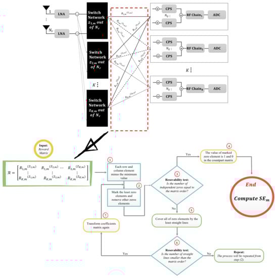
Figure 2.
Proposed matching strategy for RF chain-subset selected antennas for each AP diagram with flowchart of the Hungarian algorithm.
3.2. Problem Solution
We utilize the Hungarian method, which is a combinatorial optimization algorithm, to solve the proposed bipartite graph assignment problems in this work with K RF chains at each AP and . The reason behind assuming the length of equals the number of RF chains at each AP is to obtain a square matrix for the reward matrix in order to make the assignment operation less complicated for the proposed Hungarian algorithm.
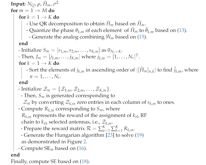
Algorithm 1 summarises the whole procedure of the proposed antenna selection matching strategy. This algorithm maximizes the EE for uplink cell-free mm-Wave massive MIMO systems. The first three steps are utilized to generate based on Equation (13) for each AP. Then, all connections between and the RF chains are in the inactive state, and antenna indices are sorted in ascending order based on the smallest channel magnitude for each AP, and symbolized as . Thus, each RF chain has several values of based on . Therefore, reward matrix describes the problem formulated in (19), and it can be solved based on the steps of the Hungarian algorithm mentioned in Algorithm 1. The Hungarian algorithm is used to arrange the reward matrix in order to maximize weight matching. Moreover, as shown in Figure 2, the suggested algorithm’s high-level diagram begins by assigning to each RF chain randomly a from the set . Then, the Hungarian algorithm starts by reducing each row in the input reward matrix, which consists of the computed with all elements of the set , by subtracting the minimum item in each row from all other items in the same row, and repeating the process for each column. Accordingly, we look for the convenient switches for each RF chain. If RF chain is already assigned to switches, it is better to be assigned with another ; we prime the alternative before moving on to the next candidate switches; however, if that is the only switches for which RF chain is qualified, we would like to reassign any other RF chain to those switches. We reassign RF chains to their alternate selected antennas to guarantee the assignment can provide the maximum spectral efficiency for each AP, which is the resolvability test. As a result, we can be confident that we progress toward our goal of identifying the best assignment with each iteration. Finally, because our proposed algorithm does not require a high number of iterations to reach the maximum total SE, especially when there exists a large number of both APs and/or equipped for each AP, this proposed technique employing a matching strategy has much lower complexity compared to the state-of-the-are schemes, as presented in Section 6.
| Algorithm 1: Matching strategy for RF chain-subset selected antennas based on the Hungarian algorithm. |
 |
4. Power Consumption and Energy Efficiency Models
Total power consumption similar to that applied in, for example, [,,,,,,], is used in the considered uplink cell-free massive MIMO systems. Therefore, the power consumed by AP fronthaul link to the CPU depends on the amount of traffic on the link that should be transferred. Thus, the power consumed by fronthaul link is given as
where gives the actual fronthaul rate between AP and the CPU and is expressed as
where and represent the number of quantization bits at AP and the coherence time (in seconds), respectively. For simplicity, we assume that all APs have the same value of , and . In addition, the power consumed by the RF chain circuit at AP is expressed as
where are the power consumed by the mixer, local oscillator, and low-pass filter, respectively. The total circuit power consumption for all APs in the considered uplink cell-free mm-Wave massive MIMO systems is expressed as
where and are the transmit power of UE and the amount of power required to operate the circuit components, respectively. is shown as where denotes the power amplifier efficiency at UE. In addition, all UEs have the same value of both and . Furthermore, , and are the power consumed by the low-noise amplifier, splitter, switch, CPSs, combiner, and analog-to-digital converter, respectively. Thus, the total uplink energy efficiency (EE), which is measured in bits per Joule, is given as
5. Simulation Results and Discussions
This section includes a comprehensive collection of simulation results that investigate the performance of our proposed matching scheme in terms of total power consumption and EE in the uplink cell-free mm-Wave massive MIMO. In order to emphasize the importance of our results through matching between several fixed values of activated antennas based on the channel quality and RF chains at each AP, our proposed scheme is compared with the methods from conventional mm-Wave multi-users MIMO in [] expanded to cell-free mm-Wave massive MIMO systems, which are decremental search-based antenna selection (DSAS), channel magnitude-based with dynamically selected antennas (CMDAS), and channel magnitude-based with fixed selected antennas (CMFAS). The proposed scheme can enhance the total EE in the cell-free uplink network and achieve the tradeoff between system performance in terms of SE, EE, and the complexity of the proposed matching scheme. Similar to what has been done in the literature on cell-free massive MIMO, and to improve the modelling of network performance by removing boundary effects, M APs are randomly distributed in a square service area, where m [,], and boundaries are wrapped around. In addition, due to the limited scattering in mm-Wave channels, the effective channel paths between UE and AP is assumed as [,,]. Based on (2), the large scale fading coefficients can be determined by setting and [,]. Table 1 contains the parameters used in all simulations in this section.

Table 1.
Simulation parameters.
Figure 3 and Figure 4 show the impact of the number of on both EE and total power consumption when , , , and the transmit power dBm. Figure 3 shows the EE for an increasing number of . It is observed that the EE for all schemes decrease when increases, which is obvious because the additional come with a resultant increase in power consumption. The proposed matching scheme for antenna selection in uplink cell-free mm-Wave massive MIMO systems is advantageous when the APs have fewer antennas or more antennas. In the case of the APs having fewer antennas, the channel quality worsens, leading to degradation in system performance in terms of the SE. However, the proposed scheme can mitigate this issue by offering each half of the RF chains be assigned to more than of the at each AP, while each of the remaining RF chains is matched to or less of . Therefore, half of the RF chains assigned to more than of the selected antennas at each AP can guarantee improvement of the sum rate, and the remaining RF chains set to or less can maximize EE. For example, when antennas are equipped for each AP, the proposed antenna matching selection strategy can achieve , , , , and compared to the CMFAS scheme with both and of the selected antennas fixed, and CMDAS, DSAS, and FCPSs in [], respectively.
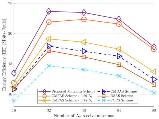
Figure 3.
EE versus number of antennas, where APs, , dBm, and UEs.
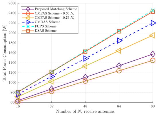
Figure 4.
Total power consumption versus number of antennas, where APs, , dBm, and UEs.
On the other side, Figure 4 shows total power consumption increases when increases. It is obvious that CMFAS with of the selected antennas fixed has the lowest total power consumption. Then, the proposed matching scheme comes in second place and then CMDAS, DSAS, and FCPSs, in which DSAS and FCPSs attain similar total power consumption. Therefore, it can be seen that the proposed matching based on the Hungarian algorithm can outperform CMDAS, DSAS, and FCPSs. For example, when , the proposed matching scheme uses W, while CMFAS with of the selected antennas fixed uses W. In addition, CMDAS, DSAS, and FCPSs use W, W, and W, respectively.
Figure 5 shows EE performance against increasing number M of APs for , , , and dBm. As the number of APs increases, we observe that the EE of all schemes decreases. This is because the power consumption of each AP rises as well, owing to the inclusion of massive hardware components such as RF chains, CPSs, analog-to-digital converters, and so on. This can lead to a decrease in the EE. However, the proposed matching scheme can achieve satisfactory performance concerning the EE over all the schemes mentioned in this paper. However, DSAS lowers EE compared to all other techniques. This is appropriate since the design of for each RF chain excludes a small number of antennas, and these antennas are switched OFF because of their considerable contribution to the interference signals at each AP.
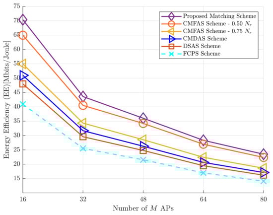
Figure 5.
EE versus number of APs, where APs, , dBm, and UEs.
Figure 6 presents that total power consumption increases when M increases. It can be seen that CMFAS with of the selected antennas has the lowest total power consumption. Then, the proposed matching strategy comes after CMFAS with of the selected antennas. This is because the number of selected antennas for each RF chain at each AP plays an important role in minimising total power consumption. Furthermore, it is noted that the number of selected antennas for each RF chain at each AP is no more than in CMFAS, which can lead to lower total power consumption. Therefore, activating a large number of antennas at all the APs causes extremely high power consumption for the uplink cell-free mm-Wave massive MIMO system, as illustrated in the state-of-the-art schemes, motivating the proposed matching scheme in this work to maintain lower power consumption by matching half of the RF chains at each AP to a large number of active antennas to mitigate a significant loss in the SE, while the rest of the RF chains are assigned to fewer selected antennas to maximize the EE. Thus, it can be noted that the proposed matching scheme can overcome DSAS, CMFAS with of the selected antennas, CMDAS, and FCPSs.
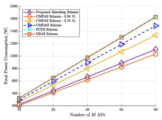
Figure 6.
Total power consumption versus number of APs, where APs, , dBm, and UEs.
Figure 7 demonstrates the impact of K UEs on the EE of the uplink cell-free mm-Wave massive MIMO network when , , and dBm. It is obvious that the EE increases as K increases. This is because inter-user interference cannot affect the SE of the uplink systems. In particular, it indicates that large K UEs in the proposed matching perform better than other schemes in terms of SE. This is because with more data streams received, the chance that the optimal large number of antennas are activated for the half of RF chains at each AP increases. This will enhance the preservation of the system from significant loss in SE. In contrast, the rest of the RF chains are responsible for maintaining EE by choosing a lower number of optimally selected antennas. Compared with the extended schemes and FCPSs, the proposed matching technique provides much-enhanced EE, as anticipated. For example, when UEs, the proposed matching scheme can attain approximately , , , , and EE improvement compared to CMFAS with and of the selected antennas, CMDAS, DSAS, and FCPSs. We also observe that the proposed matching scheme can optimize SE and EE. In contrast, other schemes, namely, DSAS and CMDAS, seek to optimize only the SE without taking into consideration the total power consumption, especially when the cell-free network has a large number of M APs, antennas, and K UEs.
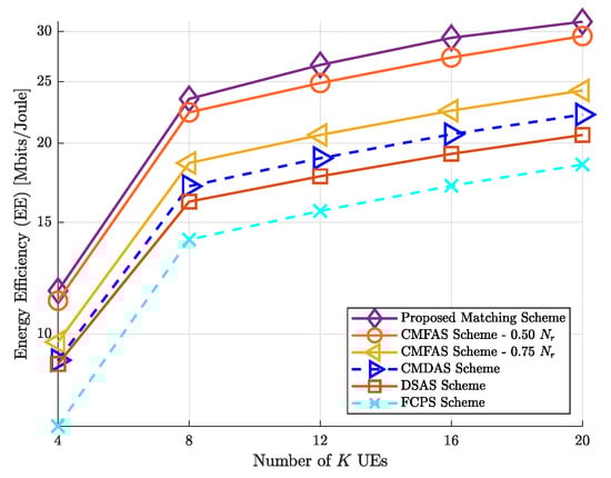
Figure 7.
EE versus number of UEs, where APs, , dBm, and .
Figure 8 presents clear gains in the total power consumption obtained by the extended and proposed schemes in this paper. Figure 8 also demonstrates that when K increases, so should the total power consumption. For example, the proposed matching scheme uses W, while CMFAS with of the selected antennas fixed uses W with , , , , and dBm. In addition, the proposed matching scheme achieves lower total power consumption compared to DSAS, CMDAS, CMFAS with of the selected antennas fixed, and FCPSs by , , and , respectively.
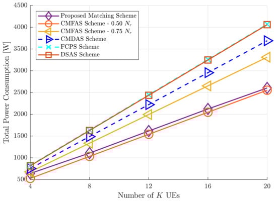
Figure 8.
Total power consumption versus the number of UEs, where APs, , dBm, and .
6. Complexity Analysis
The computational complexity analysis is the last intriguing result worth highlighting. Floating-points operations (FLOPs) [] are used to assess the complexity of the algorithms proposed in this paper. Figure 9 compares the FLOPs versus the number of APs, the number of , and the number of UEs for the uplink cell-free mm-Wave massive MIMO system. Because DSAS executes more iterations to acquire the antenna subset selection solution, it has higher complexity than CMDAS and CMFASs. In contrast, the proposed matching scheme overcomes DSAS and CMDAS and attains an approximate number of FLOPs. Figure 9a shows the FLOPs versus the number of APs, and it is obvious that the proposed matching scheme can overcome DSAS and CMDAS by achieving and complexity reduction ratio compared to CMDAS and DSAS, respectively. Figure 9b,c also present the FLOPs against the number of antennas and the number K of UEs in the cell-free network, respectively. It can be seen that the proposed matching scheme achieves lower computational complexity concerning the number of FLOPs versus both and K compared to CMDAS and DSAS. It is also noteworthy that although our proposed matching scheme based on the Hungarian algorithm has a slightly higher complexity compared to the CMFAS, it is evident that the proposed matching scheme has better EE with all investigated scenarios of uplink cell-free mm-Wave massive MIMO systems.

Figure 9.
Complexity analysis based on floating-points operations (FLOPs) with different scenarios of uplink cell-free mm-Wave massive MIMO systems. (a) FLOPs versus M APs for a system with , , dBm, and CPSs. (b) FLOPs versus antennas with , , dBm, and CPSs. (c) FLOPs versus the number of K UEs with, , , dBm, and CPSs.
Moreover, the computational complexities of the proposed schemes can be affected by the number of required iterations to obtain the optimal number of selected antennas for each RF chain at each AP, which results in obtaining the maximum , and the number of iterations is affected by the number of antennas and the number of APs in the coverage area. Furthermore, the number of iterations is given by for DSAS, for CMDAS, and for both the matching strategy for antenna selection based on the Hungarian algorithm and CMFAS. Thus, the computational complexity to obtain the total SE for all APs in the cell-free systems based on (17) is . It is noticeable that DSAS requires many iterations, especially when the M APs and the equipped for each AP is vast. For example, if , APs, and UEs, the required total number of iterations to obtain the maximum total SE is around 16,380 for all APs. While CMDAS needs 2048 iterations to reach the maximum total SE. In addition, the channel magnitude with the predefined value of selected antennas for each AP based on the channel condition strategy has the lowest number of iterations, which is equal to the number of APs inside the coverage area. Regarding the proposed matching algorithm based on the Hungarian method strategy, if (i.e., ), then its computational complexity is , and the required number of iterations to obtain the maximum total spectral efficiency is also equal to the number of APs, which is considered to be similar to the channel magnitude with predefined value of the selected antennas based on the channel condition scheme. In addition, if (i.e., ), then the computational complexity of the proposed matching algorithm based on the Hungarian method strategy is [], which is similar to the Hungarian algorithm complexity analysis multiplied by ı, which is equal to the number of APs in the cell-free network, and in this case, the proposed matching scheme for antenna selection has higher complexity than the channel magnitude with the predefined value of the selected antennas based on the channel condition scheme. Therefore, when comparing the proposed matching scheme for antenna selection for each RF chain at each AP to DSAS and CMDAS, the proposed matching strategy can yield a computational complexity reduction of around .
Finally, in uplink cell-free mm-Wave massive MIMO systems, there is a tradeoff between EE, SE, and the number of FLOPs used as a complexity analysis in this paper. Figure 10 illustrates this tradeoff. The solid curves in this figure show the proposed matching scheme’s energy efficiency, spectral efficiency, and FLOPs tradeoff when , , dBm, CPSs, and . In addition, the dashed curves demonstrate the EE, SE, and the FLOPs tradeoff when . The EE decreases when both M APs and increase while the SE increases. The FLOPs present a reverse trend when compared with the EE and SE tradeoff, i.e., FLOPs increase when both M APs and increase.
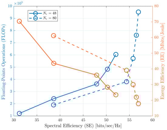
Figure 10.
EE and SE and the complexity tradeoff as a function of the number M of APs when , , dBm, CPSs, and for the proposed matching scheme in uplink cell-free mm-Wave massive MIMO systems.
Analysis of the simulation results provides clear insight into antenna selection techniques for uplink cell-free mm-Wave massive MIMO systems when different scenarios of M APs, K UEs, and are considered. Overall, the results confirm that the proposed matching strategy based on the Hungarian method can provide better EE and lower complexity compared to the other schemes. Moreover, the proposed matching scheme for antenna selection can achieve a tradeoff between SE, EE, total power consumption, and computational complexity.
7. Conclusions
In this paper, we investigate a hybrid analog/digital scheme with CPSs and antenna selection technique based on matching theory for uplink cell-free mm-Wave massive MIMO systems to achieve two objectives: enhancement of the EE and low computational complexity. These two objectives have been addressed by introducing a novel matching scheme based on the Hungarian algorithm for maximum weight matching. In a first step, the assignment optimization problem is formulated to match the RF chains at each AP in the coverage area and several sets of activated antennas based on the channel magnitude. In a second step, the Hungarian method is proposed to solve the formulated optimization problem due to its computational complexity. The efficiency of the proposed matching scheme for the antenna selection technique is justified by the simulation results, with several scenarios of uplink cell-free mm-Wave massive MIMO systems, which show that the matching approach can attain around EE improvement and complexity reduction compared to the state-of-the-art schemes. Thanks to the matching theory, half of the RF chains at each AP are connected to a minimum number of selected antennas in the proposed matching method. In contrast, each of the remaining RF chains is connected to a large number of selected antennas. Based on this finding, the tradeoff between SE, total power consumption, and computational complexity can be guaranteed. For future work, the proposed antenna selection based on the matching technique can be integrated with low-resolution ADCs due to the capability of our proposed scheme based on channel quality to enhance EE without significant loss in SE with low computational complexity.
Author Contributions
Conceptualization, A.A.A. and Y.S.; methodology, A.A.A. and Y.S.; software, A.A.A.; validation, A.A.A., Y.S., S.O. and S.A.; formal analysis, A.A.A.; investigation, A.A.A. and Y.S.; resources, A.A.A.; data curation, A.A.A.; writing—original draft preparation, A.A.A.; writing—review and editing, A.A.A. and Y.S.; visualization, A.A.A.; supervision, M.A.I. All authors have read and agreed to the published version of the manuscript.
Funding
This research was fully funded by a scholarship for A. A. Ayidh from the Saudi Arabian Cultural Bureau in the UK.
Institutional Review Board Statement
Not applicable.
Informed Consent Statement
Not applicable for studies not involving humans.
Data Availability Statement
Not applicable.
Conflicts of Interest
The authors declare no conflict of interest.
References
- WRC-19 Identifies Additional Frequency Bands for 5G—ITU Hub. Available online: https://www.itu.int/hub/2020/01/wrc-19-identifies-additional-frequency-bands-for-5g/ (accessed on 10 May 2022).
- Nguyen, N.T.; Lee, K. Coverage and Cell-Edge Sum-Rate Analysis of mmWave Massive MIMO Systems with ORP Schemes and MMSE Receivers. IEEE Trans. Signal Process. 2018, 66, 5349–5363. [Google Scholar] [CrossRef]
- Gao, X.; Dai, L.; Sayeed, A.M. Low RF-Complexity Technologies to Enable Millimeter-Wave MIMO with Large Antenna Array for 5G Wireless Communications. IEEE Commun. Mag. 2018, 56, 211–217. [Google Scholar] [CrossRef] [Green Version]
- Elhoushy, S.; Ibrahim, M.; Hamouda, W. Cell-Free Massive MIMO: A Survey. IEEE Commun. Surv. Tutor. 2022, 24, 492–523. [Google Scholar] [CrossRef]
- Ngo, H.Q.; Tran, L.N.; Duong, T.Q.; Matthaiou, M.; Larsson, E.G. On the Total Energy Efficiency of Cell-Free Massive MIMO. IEEE Trans. Green Commun. Netw. 2018, 2, 25–39. [Google Scholar] [CrossRef] [Green Version]
- Ngo, H.Q.; Ashikhmin, A.; Yang, H.; Larsson, E.G.; Marzetta, T.L. Cell-Free Massive MIMO Versus Small Cells. IEEE Trans. Wirel. Commun. 2017, 16, 1834–1850. [Google Scholar] [CrossRef] [Green Version]
- Björnson, E.; Sanguinetti, L. Making Cell-Free Massive MIMO Competitive With MMSE Processing and Centralized Implementation. IEEE Trans. Wirel. Commun. 2020, 19, 77–90. [Google Scholar] [CrossRef] [Green Version]
- Abbas, W.B.; Gomez-Cuba, F.; Zorzi, M. Millimeter Wave Receiver Efficiency: A Comprehensive Comparison of Beamforming Schemes With Low Resolution ADCs. IEEE Trans. Wirel. Commun. 2017, 16, 8131–8146. [Google Scholar] [CrossRef] [Green Version]
- Heath, R.W.; González-Prelcic, N.; Rangan, S.; Roh, W.; Sayeed, A.M. An Overview of Signal Processing Techniques for Millimeter Wave MIMO Systems. IEEE J. Sel. Top. Signal Process. 2016, 10, 436–453. [Google Scholar] [CrossRef]
- Gao, X.; Dai, L.; Han, S.; C, I.; Heath, R.W. Energy-Efficient Hybrid Analog and Digital Precoding for MmWave MIMO Systems With Large Antenna Arrays. IEEE J. Sel. Areas Commun. 2016, 34, 998–1009. [Google Scholar] [CrossRef] [Green Version]
- Alkhateeb, A.; Leus, G.; Heath, R.W. Limited Feedback Hybrid Precoding for Multi-User Millimeter Wave Systems. IEEE Trans. Wirel. Commun. 2015, 14, 6481–6494. [Google Scholar] [CrossRef] [Green Version]
- Ayach, O.E.; Rajagopal, S.; Abu-Surra, S.; Pi, Z.; Heath, R.W. Spatially Sparse Precoding in Millimeter Wave MIMO Systems. IEEE Trans. Wirel. Commun. 2014, 13, 1499–1513. [Google Scholar] [CrossRef] [Green Version]
- Han, S.; C, I.; Xu, Z.; Rowell, C. Large-scale antenna systems with hybrid analog and digital beamforming for millimeter wave 5G. IEEE Commun. Mag. 2015, 53, 186–194. [Google Scholar] [CrossRef]
- Alkhateeb, A.; Nam, Y.; Zhang, J.; Heath, R.W. Massive MIMO Combining with Switches. IEEE Wirel. Commun. Lett. 2016, 5, 232–235. [Google Scholar] [CrossRef] [Green Version]
- Sah, A.K.; Chaturvedi, A.K. Quasi-Orthogonal Combining for Reducing RF Chains in Massive MIMO Systems. IEEE Wirel. Commun. Lett. 2017, 6, 126–129. [Google Scholar] [CrossRef]
- Nguyen, L.D.; Duong, T.Q.; Ngo, H.Q.; Tourki, K. Energy Efficiency in Cell-Free Massive MIMO with Zero-Forcing Precoding Design. IEEE Commun. Lett. 2017, 21, 1871–1874. [Google Scholar] [CrossRef] [Green Version]
- Femenias, G.; Riera-Palou, F. Cell-Free Millimeter-Wave Massive MIMO Systems with Limited Fronthaul Capacity. IEEE Access 2019, 7, 44596–44612. [Google Scholar] [CrossRef]
- Nguyen, N.T.; Lee, K.; Dai, H. Hybrid Beamforming and Adaptive RF Chain Activation for Uplink Cell-Free Millimeter-Wave Massive MIMO Systems. IEEE Trans. Veh. Technol. 2022, 1. [Google Scholar] [CrossRef]
- Ayidh, A.A.; Sambo, Y.; Ansari, S.; Imran, M.A. Hybrid Beamforming with Fixed Phase Shifters for Uplink Cell-Free Millimetre-Wave Massive MIMO Systems. In Proceedings of the 2021 Joint European Conference on Networks and Communications & 6G Summit (EuCNC/6G Summit), Porto, Portugal, 8–11 June 2021; pp. 19–24. [Google Scholar]
- Méndez-Rial, R.; Rusu, C.; González-Prelcic, N.; Alkhateeb, A.; Heath, R.W. Hybrid MIMO Architectures for Millimeter Wave Communications: Phase Shifters or Switches? IEEE Access 2016, 4, 247–267. [Google Scholar] [CrossRef]
- Boroujerdi, M.N.; Abbasfar, A.; Ghanbari, M. Antenna assignment in Cell Free Massive MIMO systems. In Proceedings of the 2017 Iranian Conference on Electrical Engineering (ICEE), Tehran, Iran, 2–4 May 2017; pp. 1747–1751. [Google Scholar]
- Bahingayi, E.E.; Lee, K. Hybrid Combining Based on Constant Phase Shifters and Active/Inactive Switches. IEEE Trans. Veh. Technol. 2020, 69, 4058–4068. [Google Scholar] [CrossRef] [Green Version]
- Munkres, J. Algorithms for the assignment and transportation problems. J. Soc. Ind. Appl. Math. 1957, 5, 32–38. [Google Scholar] [CrossRef] [Green Version]
- Alkhateeb, A.; Ayach, O.E.; Leus, G.; Heath, R.W. Channel Estimation and Hybrid Precoding for Millimeter Wave Cellular Systems. IEEE J. Sel. Top. Signal Process. 2014, 8, 831–846. [Google Scholar] [CrossRef] [Green Version]
- Andrea, C.D.; Interdonato, G.; Buzzi, S. User-centric Handover in mmWave Cell-Free Massive MIMO with User Mobility. In Proceedings of the 2021 29th European Signal Processing Conference (EUSIPCO), Dublin, Ireland, 23–27 August 2021; pp. 1–5. [Google Scholar]
- Rappaport, T.S.; MacCartney, G.R.; Samimi, M.K.; Sun, S. Wideband Millimeter-Wave Propagation Measurements and Channel Models for Future Wireless Communication System Design. IEEE Trans. Commun. 2015, 63, 3029–3056. [Google Scholar] [CrossRef]
- Rappaport, T.S.; Ben-Dor, E.; Murdock, J.N.; Qiao, Y. 38 GHz and 60 GHz angle-dependent propagation for cellular & peer-to-peer wireless communications. In Proceedings of the 2012 IEEE International Conference on Communications (ICC), Ottawa, ON, Canada, 10–15 June 2012; pp. 4568–4573. [Google Scholar]
- Marzetta, T.L. Fundamentals of Massive MIMO; Cambridge University Press: Cambridge, UK, 2016. [Google Scholar]
- Elijah, O.; Leow, C.Y.; Rahman, T.A.; Nunoo, S.; Iliya, S.Z. A Comprehensive Survey of Pilot Contamination in Massive MIMO—5G System. IEEE Commun. Surv. Tutor. 2016, 18, 905–923. [Google Scholar] [CrossRef]
- Björnson, E.; Hoydis, J.; Sanguinetti, L. Massive MIMO Networks: Spectral, Energy, and Hardware Efficiency. Found. Trends Signal Process. 2017, 11, 154–655. [Google Scholar] [CrossRef]
- Li, M.; Liu, W.; Tian, X.; Wang, Z.; Liu, Q. Iterative hybrid precoder and combiner design for mmWave MIMO-OFDM systems. Wirel. Netw. 2019, 25, 4829–4837. [Google Scholar] [CrossRef] [Green Version]
- Sohrabi, F.; Yu, W. Hybrid Digital and Analog Beamforming Design for Large-Scale Antenna Arrays. IEEE J. Sel. Top. Signal Process. 2016, 10, 501–513. [Google Scholar] [CrossRef] [Green Version]
- Nayebi, E.; Ashikhmin, A.; Marzetta, T.L.; Yang, H.; Rao, B.D. Precoding and Power Optimization in Cell-Free Massive MIMO Systems. IEEE Trans. Wirel. Commun. 2017, 16, 4445–4459. [Google Scholar] [CrossRef]
- Femenias, G.; Lassoued, N.; Riera-Palou, F. Access Point Switch ON/OFF Strategies for Green Cell-Free Massive MIMO Networking. IEEE Access 2020, 8, 21788–21803. [Google Scholar] [CrossRef]
- Aguerri, I.E.; Zaidi, A.; Caire, G.; Shitz, S.S. On the Capacity of Cloud Radio Access Networks with Oblivious Relaying. IEEE Trans. Inf. Theory 2019, 65, 4575–4596. [Google Scholar] [CrossRef] [Green Version]
- Bashar, M.; Cumanan, K.; Burr, A.G.; Ngo, H.Q.; Larsson, E.G.; Xiao, P. Energy Efficiency of the Cell-Free Massive MIMO Uplink With Optimal Uniform Quantization. IEEE Trans. Green Commun. Netw. 2019, 3, 971–987. [Google Scholar] [CrossRef] [Green Version]
- García-Morales, J.; Femenias, G.; Riera-Palou, F. Energy-Efficient Access-Point Sleep-Mode Techniques for Cell-Free mmWave Massive MIMO Networks With Non-Uniform Spatial Traffic Density. IEEE Access 2020, 8, 137587–137605. [Google Scholar] [CrossRef]
- Yu, Y.; Baltus, P.G.M.; Graauw, A.D.; Heijden, E.V.D.; Vaucher, C.S.; Roermund, A.H.M.V. A 60 GHz Phase Shifter Integrated With LNA and PA in 65 nm CMOS for Phased Array Systems. IEEE J. Solid State Circuits 2010, 45, 1697–1709. [Google Scholar] [CrossRef] [Green Version]
- Chen, Z.; Björnson, E. Channel Hardening and Favorable Propagation in Cell-Free Massive MIMO With Stochastic Geometry. IEEE Trans. Commun. 2018, 66, 5205–5219. [Google Scholar] [CrossRef] [Green Version]
- Golub, G.H.; Van Loan, C.F. Matrix Computations; JHU Press: Baltimore, MD, USA, 2013. [Google Scholar]
- Jungnickel, D.; Jungnickel, D. Graphs, Networks and Algorithms; Springer: Berlin/Heidelberg, Germany, 2005; Volume 3. [Google Scholar]
Publisher’s Note: MDPI stays neutral with regard to jurisdictional claims in published maps and institutional affiliations. |
© 2022 by the authors. Licensee MDPI, Basel, Switzerland. This article is an open access article distributed under the terms and conditions of the Creative Commons Attribution (CC BY) license (https://creativecommons.org/licenses/by/4.0/).