
Super-Wideband Monopole Printed Antenna with Half-Elliptical-Shaped Patch

 , ,
, ,  and
and
Abstract
1. Introduction
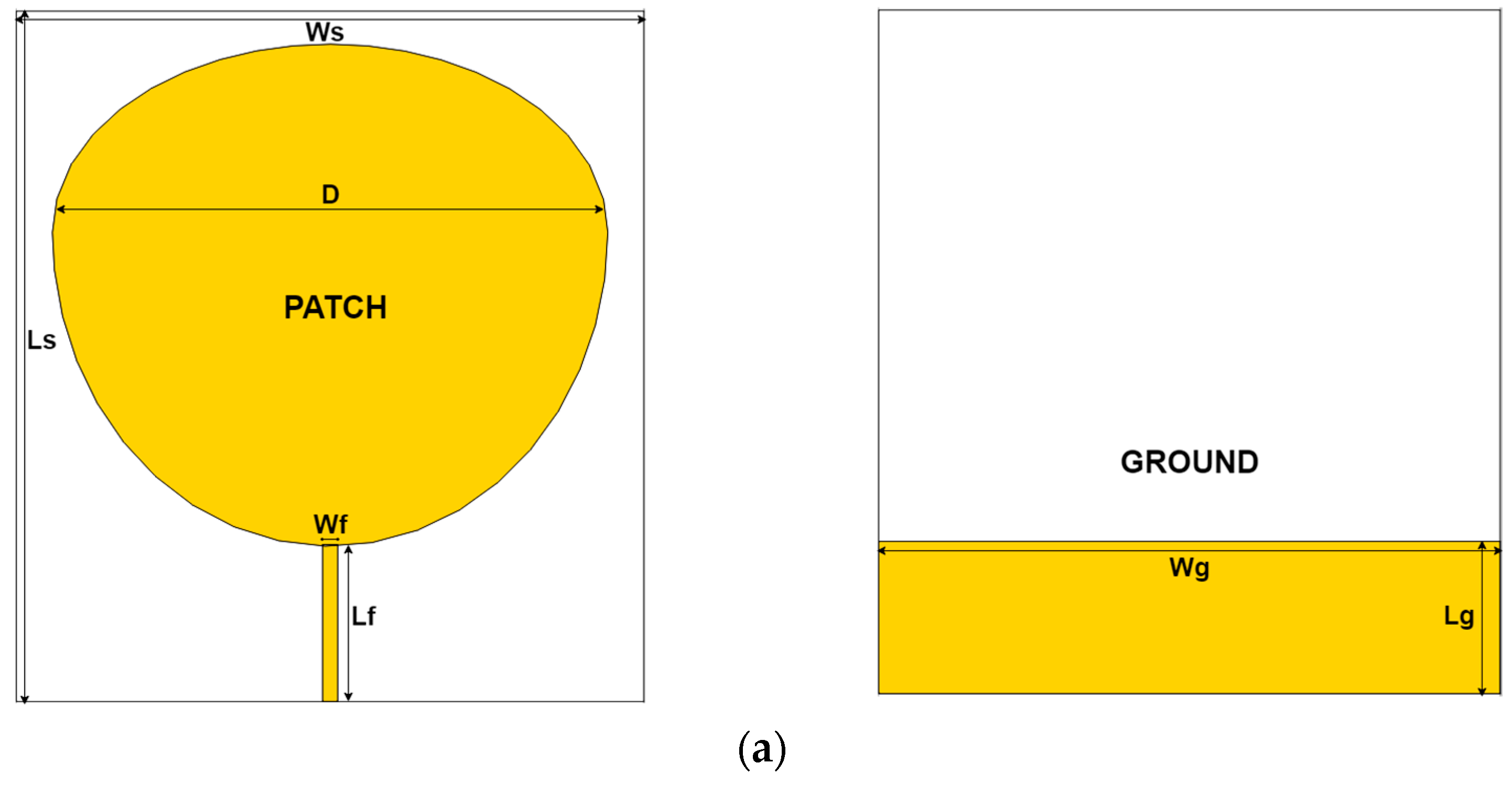
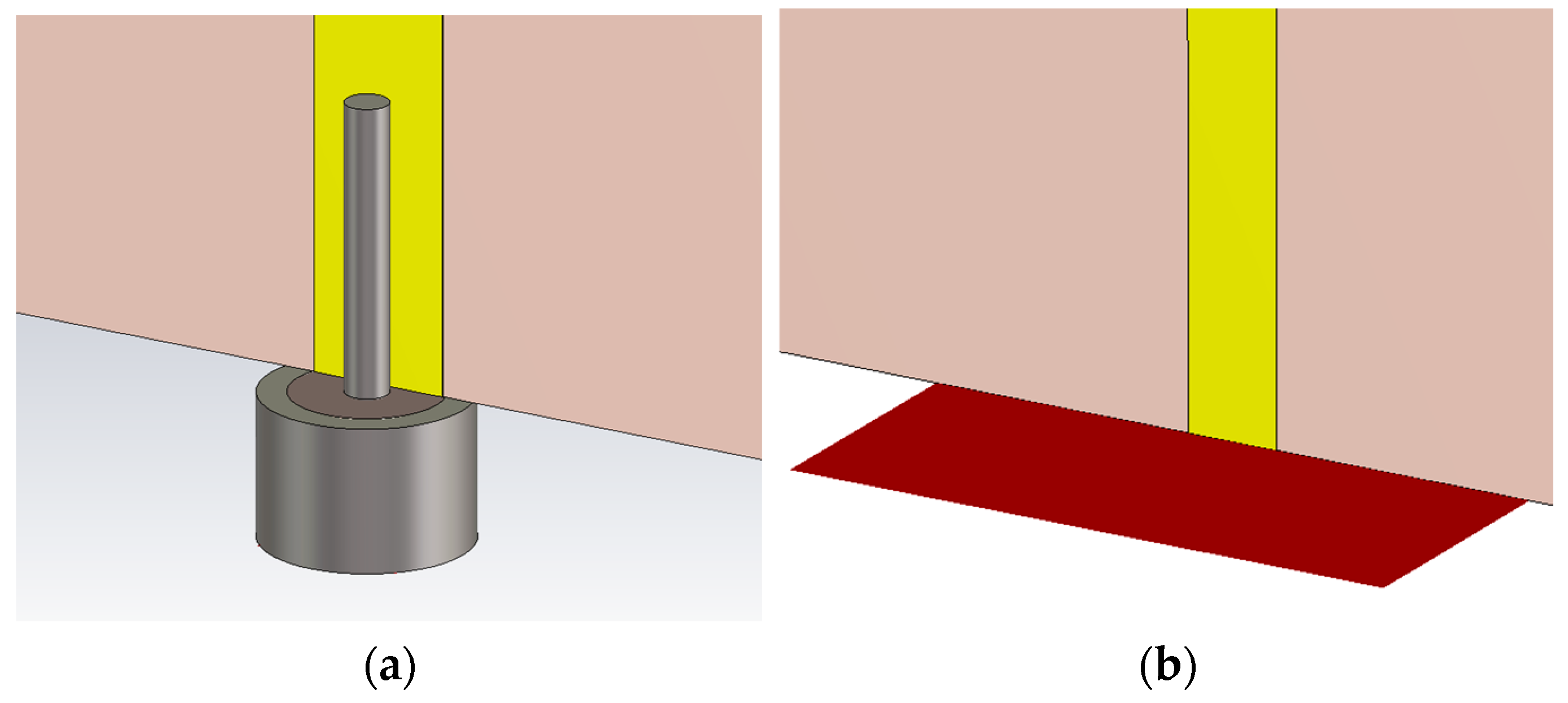
2. Antenna Design
3. Results and Discussion
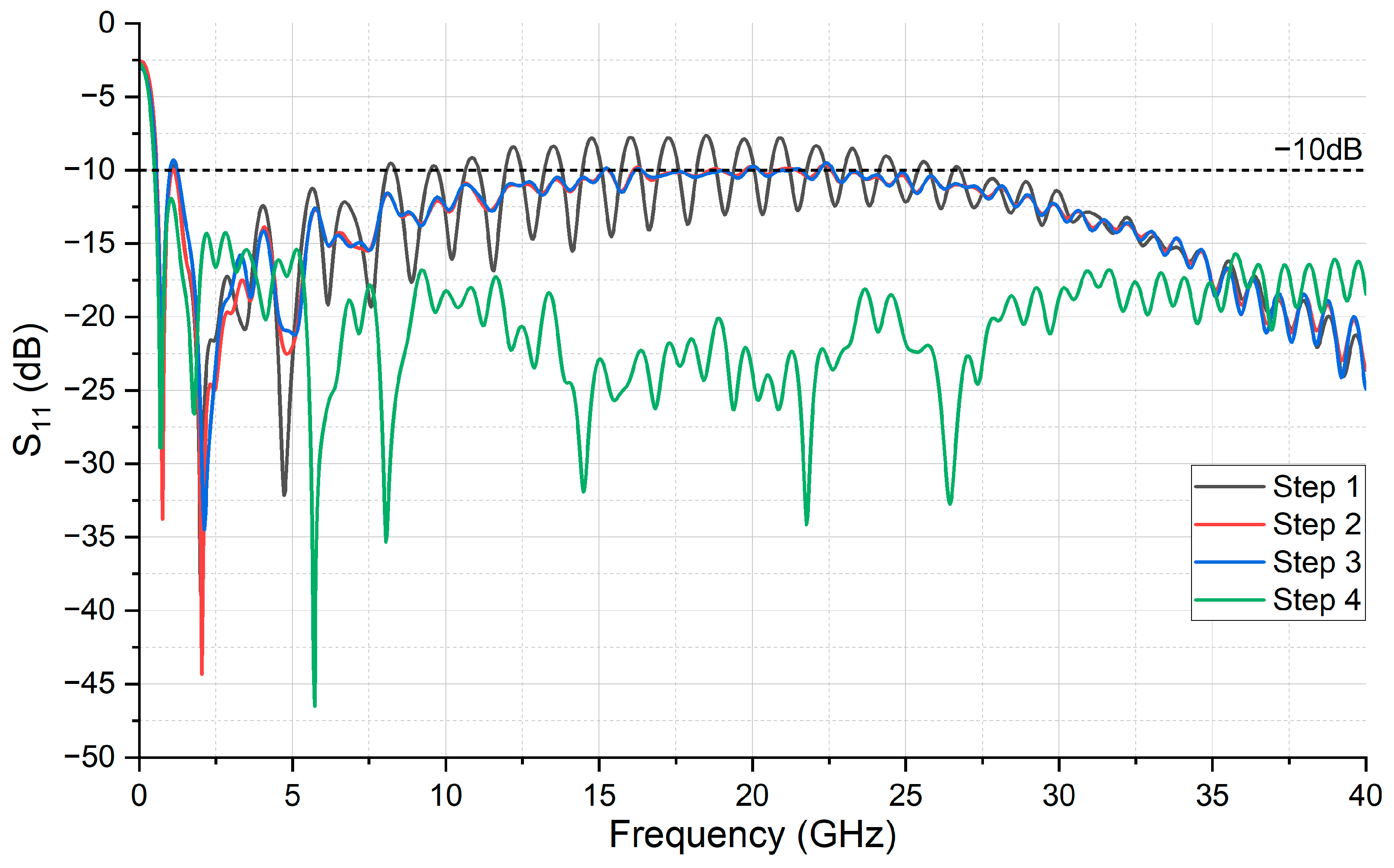
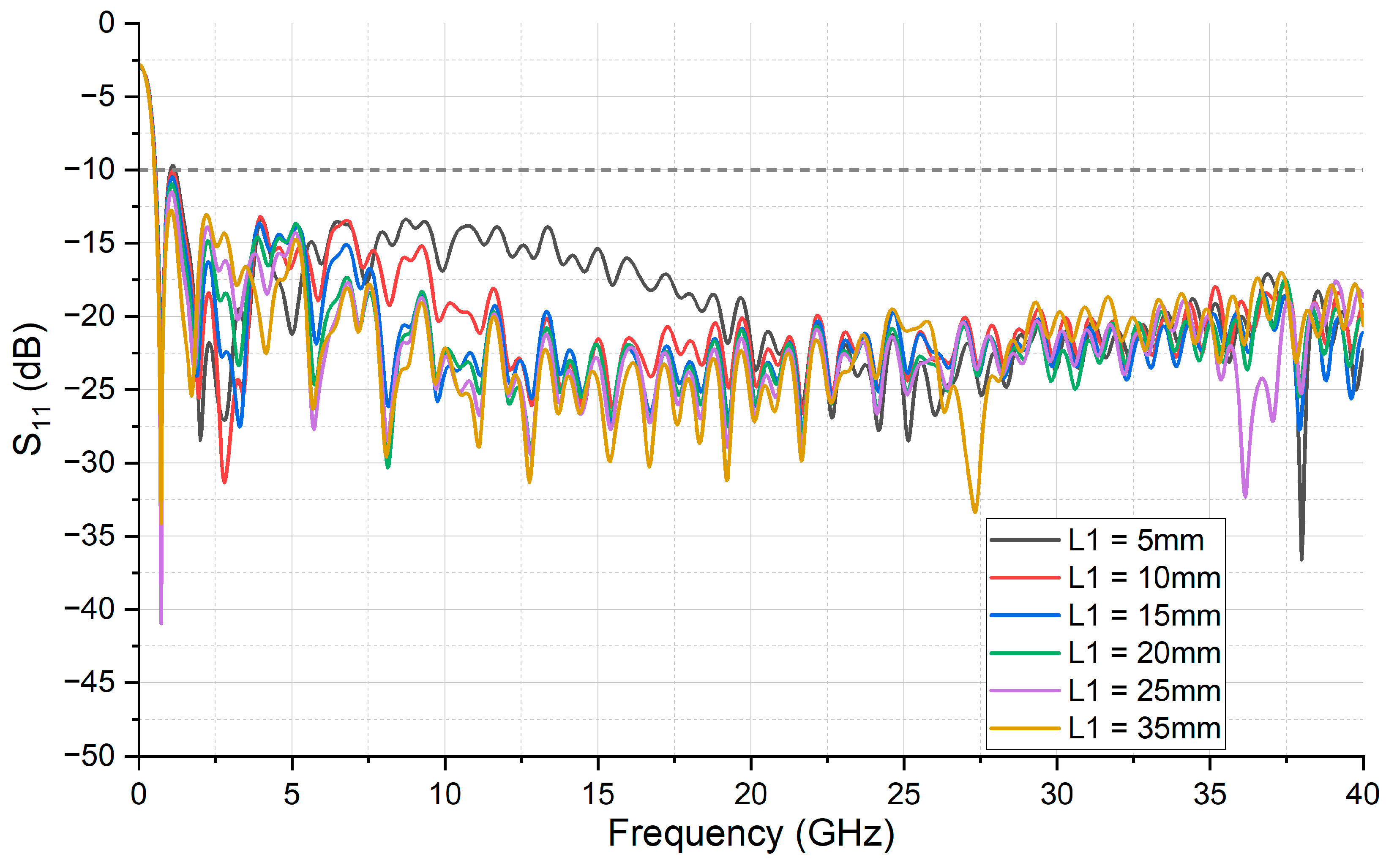
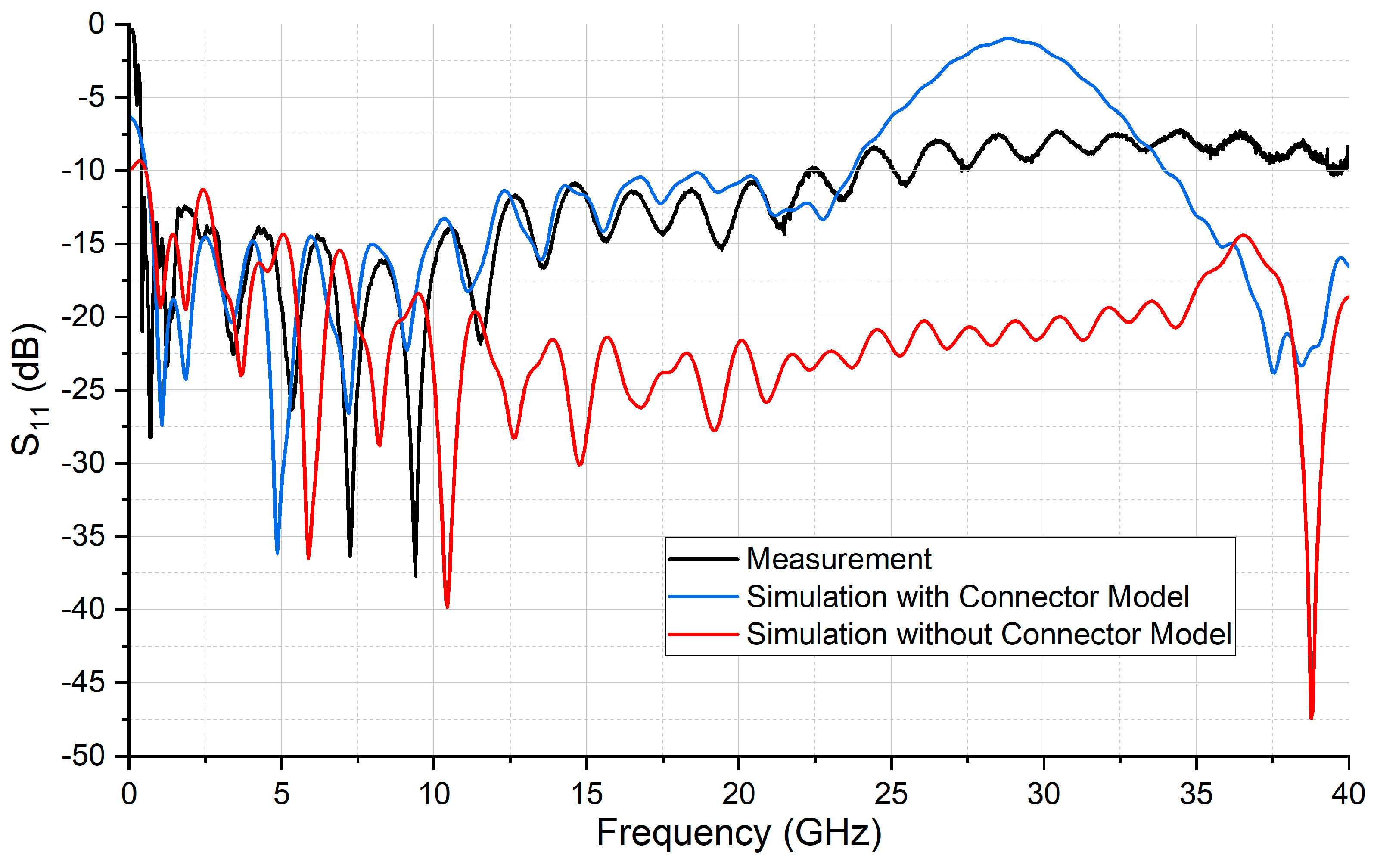
3.1. S-Parameters
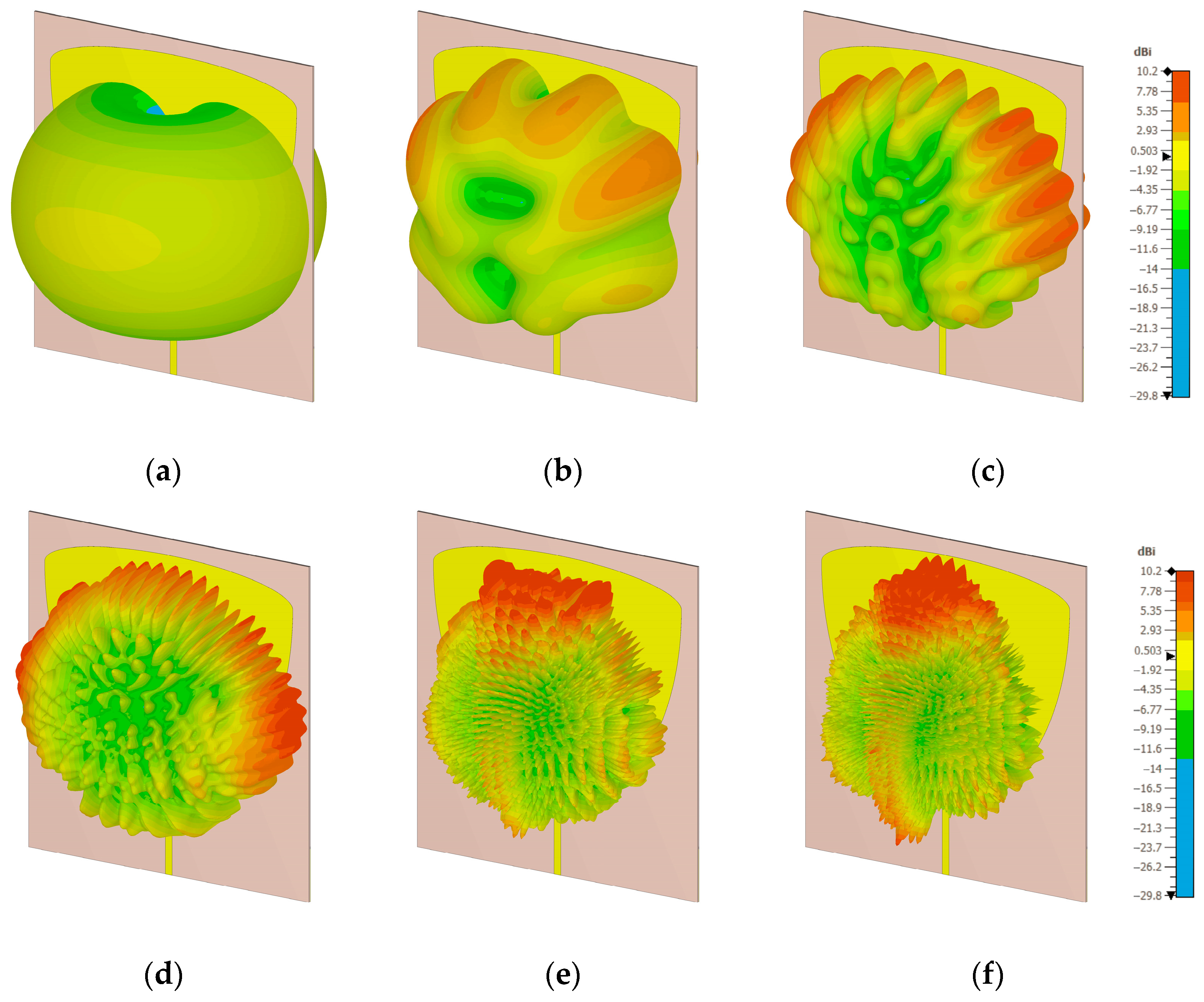
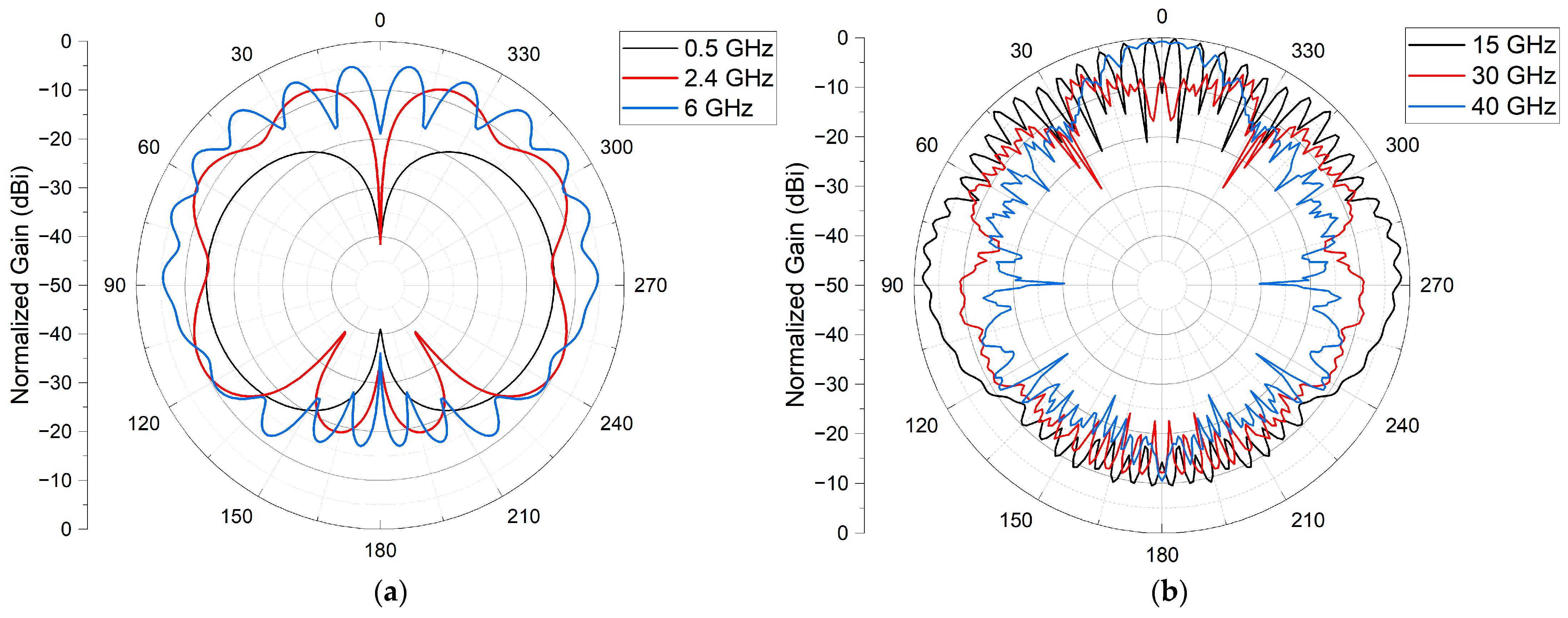
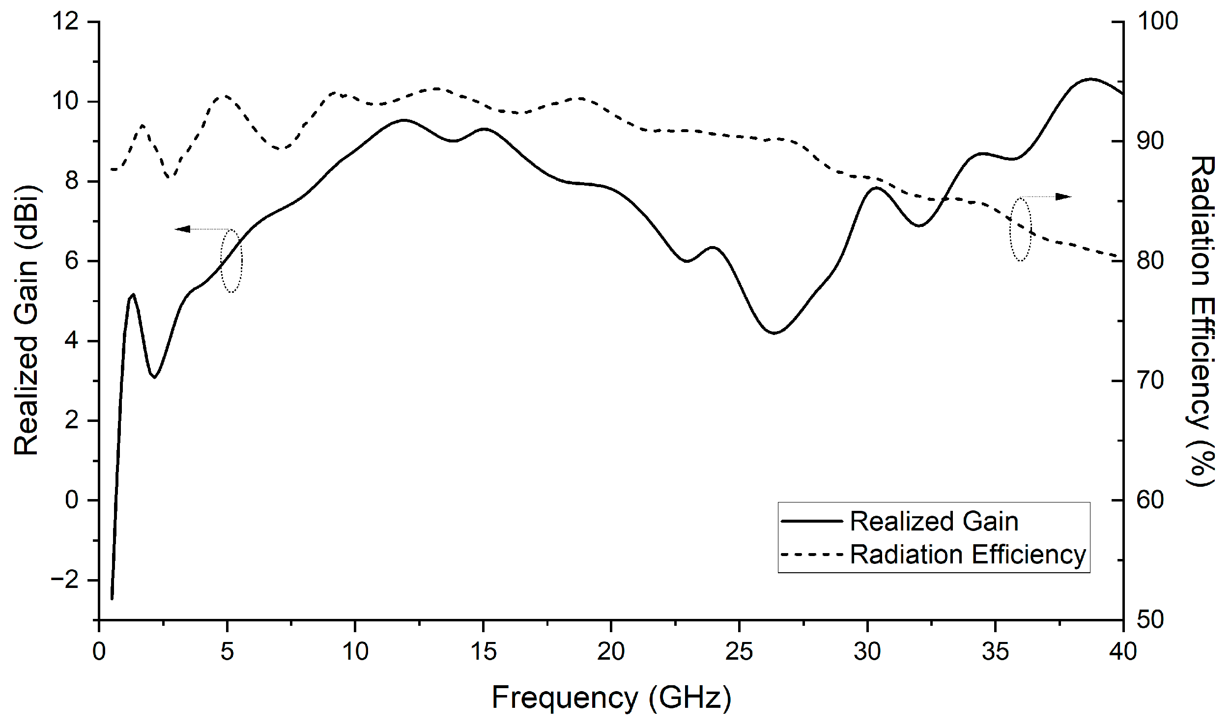
3.2. Gain and Radiation Characteristics
3.3. Measurement Results
4. Comparison of Proposed SWB Antenna with Reported Works
5. Conclusions
Author Contributions
Funding
Data Availability Statement
Conflicts of Interest
References
- Huang, Y.; Boyle, K. Antennas. From Theory to Practice; John Wiley & Sons: Hoboken, NJ, USA, 2008. [Google Scholar]
- Valderas, D. Ultrawideband Antennas; World Scientific: Singapore, 2011. [Google Scholar]
- Allen, B.; Dohler, M.; Okon, E.; Malik, W.; Brown, A.; Edwards, D. Ultra-Wideband Antennas and Propagation; John Wiley & Sons: Chichester, UK, 2006. [Google Scholar]
- FCC. First Report and Order in the Matter of Revision of Part 15 of the Commission’s Rules Regarding Ultra-Wideband Transmission Systems; FCC: Washington, DC, USA, 2002; pp. 98–153. ISSN 1937-8718.
- Balani, W.; Sarvagya, M.; Ali, T.; Pai, M.M.M.; Anguera, J.; Andujar, A.; Das, S. Design Techniques of Super-Wideband Antenna—Existing and Future Prospective. IEEE Access 2019, 7, 141241–141257. [Google Scholar] [CrossRef]
- Saleh, S.; Saeidi, T.; Timmons, N. Simple Compact UWB Vivaldi Antenna Arrays for Breast Cancer Detection. Telecom 2024, 5, 312–332. [Google Scholar] [CrossRef]
- Akrout, M.; Shyianov, V.; Bellili, F.; Mezghani, A.; Heath, R.W. Super-Wideband Massive MIMO. IEEE J. Sel. Areas Commun. 2023, 41, 2414–2430. [Google Scholar] [CrossRef]
- Agrawall, N.P.; Kumar, G.; Ray, K.P. Wide-Band Planar Monopole Antennas. IEEE Trans. Antennas Propag. 1998, 46, 294–295. [Google Scholar] [CrossRef]
- Yang, N.T.; Suh, N.S.-Y.; Nealy, R.; Davis, W.A.; Stutzman, W.L. Compact Antennas for UWB Applications. In Proceedings of the IEEE Conference on Ultra Wideband Systems and Technologies, Reston, VA, USA, 16–19 November 2003. [Google Scholar] [CrossRef]
- Yeo, J.; Lee, J. Coupled-sectorial-loop Antenna with Circular Sectors for Super Wideband Applications. Microw. Opt. Technol. Lett. 2014, 56, 1683–1689. [Google Scholar] [CrossRef]
- Elhabchi, M.; Srifi, M.N.; Touahni, R. A Novel CPW-Fed Semi-Circular Triangular Antenna with Modified Ground Plane for Super Ultra Wide Band (UWB) Applications. In Proceedings of the 2018 International Symposium on Advanced Electrical and Communication Technologies (ISAECT), Rabat, Morocco, 21–23 November 2018. [Google Scholar] [CrossRef]
- Kundu, S. A Cornetto Shaped Super Wideband Antenna for Microwave and Millimeter Wave Communication. In Proceedings of the 2022 IEEE Microwaves, Antennas, and Propagation Conference (MAPCON), Bangalore, India, 12–16 December 2022. [Google Scholar] [CrossRef]
- Singhal, S.; Singh, A.K. Asymmetrically CPW-fed Circle Inscribed Hexagonal Super Wideband Fractal Antenna. Microw. Opt. Technol. Lett. 2016, 58, 2794–2799. [Google Scholar] [CrossRef]
- Okas, P.; Sharma, A.; Gangwar, R.K. Super-wideband CPW Fed Modified Square Monopole Antenna with Stabilized Radiation Characteristics. Microw. Opt. Technol. Lett. 2018, 60, 568–575. [Google Scholar] [CrossRef]
- Hakimi, S.; Rahim, S.K.A.; Abedian, M.; Noghabaei, S.M.; Khalily, M. CPW-Fed Transparent Antenna for Extended Ultrawideband Applications. IEEE Antennas Wirel. Propag. Lett. Antennas Wirel. Propag. Lett. 2014, 13, 1251–1254. [Google Scholar] [CrossRef]
- Kumar, P.; Urooj, S.; Alrowais, F. Design of Quad-Port MIMO/Diversity Antenna with Triple-Band Elimination Characteristics for Super-Wideband Applications. Sensors 2020, 20, 624. [Google Scholar] [CrossRef] [PubMed]
- Shekhawat, S.S.; Lodhi, D.; Singhal, S. Dual Band Notched Superwideband MIMO Antenna for 5G and 6G Applications. AEÜ Int. J. Electron. Commun. 2024, 184, 155419. [Google Scholar] [CrossRef]
- Yu, C.; Yang, S.; Chen, Y.; Wang, W.; Zhang, L.; Li, B.; Wang, L. A Super-Wideband and High Isolation MIMO Antenna System Using a Windmill-Shaped Decoupling Structure. IEEE Access 2020, 8, 115767–115777. [Google Scholar] [CrossRef]
- Ayyappan, M.; Patel, P.; Kumar, H. A Dual Port Hybrid Super-Wideband MIMO Antenna with Diminished CCL and High BDR for IoT Applications. IETE J. Res. 2023, 70, 2309–2317. [Google Scholar] [CrossRef]
- Rohaninezhad, M.; Asadabadi, M.J.; Ghobadi, C.; Nourinia, J. Design and Fabrication of a Super-Wideband Transparent Antenna Implanted on a Solar Cell Substrate. Sci. Rep. 2023, 13, 9977. [Google Scholar] [CrossRef] [PubMed]
- Rafique, U.; Agarwal, S. Postcard Shaped Super Wideband Antenna with High BDR. In Proceedings of the 2021 International Conference on Radar, Antenna, Microwave, Electronics, and Telecommunications (ICRAMET), Bandung, Indonesia, 23–24 November 2021; pp. 64–67. [Google Scholar] [CrossRef]
- Rahman, M.N.; Islam, M.T.; Mahmud, M.Z.; Samsuzzaman, M. Compact Microstrip Patch Antenna Proclaiming Super Wideband Characteristics. Microw. Opt. Technol. Lett. 2017, 59, 2563–2570. [Google Scholar] [CrossRef]
- Khurshid, A.; Dong, J.; Ahmad, M.S.; Shi, R. Optimized Super-Wideband MIMO Antenna with High Isolation for IoT Applications. Micromachines 2022, 13, 514. [Google Scholar] [CrossRef] [PubMed]
- Agrawal, S.; Parihar, M.S. The Design and Investigation of a Super Wideband Antenna with Dual-Band Notch Characteristics for MIMO Application. IETE Tech. Rev. 2023, 41, 366–376. [Google Scholar] [CrossRef]
- Alluri, S.; Rangaswamy, N. A Super Wideband Circular Monopole Antenna. In Proceedings of the 2019 TEQIP III Sponsored International Conference on Microwave Integrated Circuits, Photonics and Wireless Networks (IMICPW), Tiruchirappalli, India, 22–24 May 2019. [Google Scholar] [CrossRef]
- Chen, N.K.-R.; Sim, C.-Y.-D.; Row, N.J.-S. A Compact Monopole Antenna for Super Wideband Applications. IEEE Antennas Wirel. Propag. Lett. Antennas Wirel. Propag. Lett. 2011, 10, 488–491. [Google Scholar] [CrossRef]
- Balani, W.; Sarvagya, M.; Samasgikar, A.; Ali, T.; Kumar, P. Design and Analysis of Super Wideband Antenna for Microwave Applications. Sensors 2021, 21, 477. [Google Scholar] [CrossRef] [PubMed]
- Esmail, B.A.F.; Rahim, M.K.A.; Samsuri, N.A.; Ayop, O.; Murad, N.A.; Majid, H.A.; Keriee, H.; Ghawbar, F. Design of Compact Dual-Port Super Wideband MIMO Antennas for Communication Systems. In Proceedings of the 2021 IEEE Asia-Pacific Conference on Applied Electromagnetics (APACE), Penang, Malaysia, 20–22 December 2021. [Google Scholar] [CrossRef]
- Oskouei, H.D.; Mirtaheri, A. A Monopole Super Wideband Microstrip Antenna with Band-Notch Rejection. In Proceedings of the 2017 Progress in Electromagnetics Research Symposium—Fall (PIERS—FALL), Singapore, 19–22 November 2017. [Google Scholar] [CrossRef]
- Esmail, B.A.F.; Koziel, S.; Pietrenko-Dabrowska, A. Design and Optimization of a Compact Super-Wideband MIMO Antenna with High Isolation and Gain for 5G Applications. Electronics 2023, 12, 4710. [Google Scholar] [CrossRef]
- Boologam, A.V.; Krishnan, K.; Palaniswamy, S.K.; Manimegalai, C.T.; Gauni, S. On the Design and Analysis of Compact Super-Wideband Quad Element Chiral MIMO Array for High Data Rate Applications. Electronics 2020, 9, 1995. [Google Scholar] [CrossRef]
- Prasetyo, A.D.; Sulistyaningsih, N.; Cahyaningsih, E.; Munir, A. A Compact Spearhead-Shaped Antenna with Super-Wideband Characteristics. In Proceedings of the 15th Global Symposium on Millimeter-Waves & Terahertz (GSMM), Hong Kong, China, 20–22 May 2024. [Google Scholar] [CrossRef]
- Samsuzzaman, M.; Islam, M.T. A Semicircular Shaped Super Wideband Patch Antenna with High Bandwidth Dimension Ratio. Microw. Opt. Technol. Lett. 2014, 57, 445–452. [Google Scholar] [CrossRef]
- Rafique, U.; Din, S.U. Beveled-Shaped Super-Wideband Planar Antenna. Turk. J. Electr. Eng. Comput. Sci. Elektr. 2018, 26, 2417–2425. [Google Scholar] [CrossRef]
- Naik, S.; Upmanyu, A.; Sharma, M. A Super-Wideband Flexible Four-Port MIMOsup Antenna for ON-Body Multi-Band Applications with Bandwidth Ratio 19.38:1. In Proceedings of the 11th International Conference on Reliability, Infocom Technologies and Optimization (Trends and Future Directions) (ICRITO), Noida, India, 14–15 March 2024. [Google Scholar] [CrossRef]
- Devana, V.N.K.R.; Beno, A.; Alzaidi, M.S.; Krishna, P.B.M.; Divyamrutha, G.; Awan, W.A.; Alghamdi, T.A.H.; Alathbah, M. A High Bandwidth Dimension Ratio Compact Super Wide Band-Flower Slotted Microstrip Patch Antenna for Millimeter Wireless Applications. Heliyon 2024, 10, e23712. [Google Scholar] [CrossRef] [PubMed]
- Agrawal, S.; Soni, P.K. A Conical Shape Monopole THz Super Wideband Antenna for MIMO Application. In Proceedings of the 2022 IEEE Microwaves, Antennas, and Propagation Conference (MAPCON), Bangalore, India, 12–16 December 2022. [Google Scholar] [CrossRef]
- Azari, A. A New Super Wideband Fractal Microstrip Antenna. IEEE Trans. Antennas Propag. 2011, 59, 1724–1727. [Google Scholar] [CrossRef]
- Suguna, N.; Revathi, S. A Compact Super-Wideband High Bandwidth Dimension Ratio Octagon-Structured Monopole Antenna for Future-Generation Wireless Applications. Appl. Sci. 2023, 13, 5057. [Google Scholar] [CrossRef]
- Shahu, B.L.; Pal, S.; Chattoraj, N. Design of Super Wideband Hexagonal-shaped Fractal Antenna with Triangular Slot. Microw. Opt. Technol. Lett. 2015, 57, 1659–1662. [Google Scholar] [CrossRef]
- Singhal, S.; Singh, A.K. Modified Star-star Fractal (MSSF) Super-wideband Antenna. Microw. Opt. Technol. Lett. 2017, 59, 624–630. [Google Scholar] [CrossRef]
- Singhal, S.; Singh, A.K. CPW-fed Hexagonal Sierpinski Super Wideband Fractal Antenna. IET Microw. Antennas Propag. 2016, 10, 1701–1707. [Google Scholar] [CrossRef]
- Rahman, M.A.; Al-Bawri, S.S.; Abdulkawi, W.M.; Aljaloud, K.; Islam, M.T. A Unique SWB Multi-Slotted Four-Port Highly Isolated MIMO Antenna Loaded with Metasurface for IOT Applications-Based Machine Learning Verification. Eng. Sci. Technol. Int. J. 2024, 50, 101616. [Google Scholar] [CrossRef]
- Balanis, C.A. Antenna Theory: Analysis and Design; John Wiley & Sons: Hoboken, NJ, USA, 2016; ISBN 1118642066. [Google Scholar]


| Parameters | Dimension | Parameters | Dimension |
|---|---|---|---|
| Ws | 200 | R2 | 20 |
| Ls | 220 | R3 | 15 |
| Wf | 4.8 | W1 | 3 |
| Lf | 50 | L1 | 35 |
| D | 177 | Lg | 49 |
| R1 | 140 |
| No | Design | Operating Frequency, GHz | Bandwidth | Bandwidth Ratio |
|---|---|---|---|---|
| 1 | L1 = 5 mm | 0.536–1.03 | 0.494 | 1.92 |
| 1.18–40 | 38.82 | 33.89 | ||
| 2 | L1 = 10 mm | 0.53–40 | 39.47 | 75.47 |
| 3 | L1 = 15 mm | 0.525–40 | 39.475 | 76.2 |
| 4 | L1 = 20 mm | 0.52–40 | 39.48 | 76.92 |
| 5 | L1 = 25 mm | 0.514–40 | 39.486 | 77.82 |
| 6 | L1 = 35 mm | 0.5–40 | 39.5 | 80 |
| Ref. | Dimension (λ0) | Substrate Material | Operating Frequency (GHz) | Bandwidth Ratio | Result Type |
|---|---|---|---|---|---|
| [8] | 0.98 × 0.98 | Metal Disc | 1.21–13 | 1:10.7 | Measurement |
| [9] | 0.38 × 0.38 | Metal Disc | 3–12 | 1:4 | Measurement |
| [10] | 3.8 × 3.8 | FR4 (h = 0.8 mm) | 1–19.4 | 1:19.4 | Measurement |
| [11] | 0.67 × 0.5 | FR4 (h = 1.6 mm) | 4.9–25 | 1: 5.1 | Measurement |
| [12] | 4.9 × 3.9 | FR4 (h = 0.8 mm) | 1.99–60 | 1:30 | Measurement |
| [13] | 3.18 × 3.07 | FR4 (h = 1.6 mm) | 2.75–71 | 1:25.8 | Measurement |
| [14] | 1.11 × 0.98 | RT5880 (h = 1.6 mm) | 0.95–13.8 | 1:14.52 | Measurement |
| [15] | 2.16 × 1.44 | AgHT−8 (h = 3 mm) | 3.15–32 | 1:10.5 | Measurement |
| [16] | 2.09 × 1.96 | FR4 (h = 1.6 mm) | 1.3–40 | 1:31 | Measurement |
| [17] | 1.67 × 3.49 | FR4 (h = 1.6 mm) | 4.1–60 | 1:14.6 | Measurement |
| [18] | 1.79 × 1.36 | FR4 (h = 1 mm) | 2.9–40 | 1:13 | Measurement |
| [19] | 3.65 × 4 | FR4 (h = 0.787 mm) | 1.25–50 | 1:40 | Measurement |
| [20] | 1.45 × 1.35 | FR4 (h = 1.6 mm) | 2–32 | 1:16 | Measurement |
| [21] | 0.9 × 0.9 | RT5880 (h = 1.57 mm) | 2.75–30 | 1:10.9 | Simulation |
| [22] | 1.41 × 0.97 | FR4 (h = 1.6 mm) | 2.5–29 | 1:11.6 | Measurement |
| [23] | 1.03 × 0.69 | FR4 (h = 1.2 mm) | 2.3–23 | 1:10 | Measurement |
| [24] | 0.97 × 1.46 | FR4 (h = 1.6 mm) | 2.6–27 | 1:10.3 | Measurement |
| [25] | 1.46 × 1.4 | FR4 (h = 1.6 mm) | 1.7–20 | 1:11.8 | Simulation |
| [26] | 1.01 × 1.24 | FR4 (h = 1.6 mm) | 1.44–18.8 | 1:13 | Measurement |
| [27] | 3.47 × 3.08 | RT5880 (h = 1.57 mm) | 1.25–47.5 | 1:38 | Measurement |
| [28] | 1.09 × 1.09 | FR4 (h = 1.6 mm) | 3.6–36.5 | 1:10 | Simulation |
| [29] | 2.35 × 2.35 | FR4 (h = 1.6 mm) | 3–50 | 1:16 | Measurement |
| [30] | 2.22 × 2.22 | RT5880 (h = 0.787 mm) | 3.4–70 | 1:20.5 | Measurement |
| [31] | 1.44 × 0.9 | FR4 (h = 0.8 mm) | 2.9–30 | 1:10.3 | Measurement |
| [32] | 2.66 × 3.32 | RT5880 (h = 1.57 mm) | 3.6–43.5 | 1:11.8 | Measurement |
| [33] | 1.62 × 1.3 | RT5870 (h = 1.57 mm) | 1.3–20 | 1:15.3 | Measurement |
| [34] | 2.62 × 2.62 | RT5880 (h = 1.57 mm) | 0.3–20 | 1:66.6 | Measurement |
| [35] | 3.1 × 3.1 | RT5880 (h = 0.254 mm) | 5.1–100 | 1:19.6 | Simulation |
| [36] | 0.84 × 1.16 | FR4 (h = 1.6 mm) | 1.05–32.7 | 1:31 | Measurement |
| [37] | 1.73 × 2.12 | FR4 (h = 0.001 mm) | 2200–60,000 | 1:27.2 | Simulation |
| [38] | 4 × 4 | RogersTMM (h = 1.524 mm) | 10–50 | 1:50 | Simulation |
| [39] | 7.78 × 8.89 | RT5880 (h = 0.787 mm) | 3.71–337 | 1:90 | Simulation |
| [40] | 1.06 × 1.78 | RT5880 (h = 1.57 mm) | 3–35 | 1:11.6 | Measurement |
| [41] | 1.55 × 1.5 | FR4 (h = 1.6 mm) | 4.6–52 | 1:11.3 | Measurement |
| [42] | 1.69 × 1.57 | FR4 (h = 1.6 mm) | 3.4–37.2 | 1:11 | Measurement |
| [43] | 1.2 × 1.2 | RT5880 (h = 1.6 mm) | 1.9–20 | 1:10.5 | Measurement |
| This Work | 7.6 × 7.6 | TLY-5 (h = 1.57 mm) | 0.5–23.5 | 1:47 | Measurement |
Disclaimer/Publisher’s Note: The statements, opinions and data contained in all publications are solely those of the individual author(s) and contributor(s) and not of MDPI and/or the editor(s). MDPI and/or the editor(s) disclaim responsibility for any injury to people or property resulting from any ideas, methods, instructions or products referred to in the content. |
© 2024 by the authors. Licensee MDPI, Basel, Switzerland. This article is an open access article distributed under the terms and conditions of the Creative Commons Attribution (CC BY) license (https://creativecommons.org/licenses/by/4.0/).
Share and Cite
Zulkifli, F.Y.; Wahdiyat, A.I.; Zufar, A.; Nurhayati, N.; Setijadi, E. Super-Wideband Monopole Printed Antenna with Half-Elliptical-Shaped Patch. Telecom 2024, 5, 760-773. https://doi.org/10.3390/telecom5030038
Zulkifli FY, Wahdiyat AI, Zufar A, Nurhayati N, Setijadi E. Super-Wideband Monopole Printed Antenna with Half-Elliptical-Shaped Patch. Telecom. 2024; 5(3):760-773. https://doi.org/10.3390/telecom5030038
Chicago/Turabian StyleZulkifli, Fitri Yuli, Aditya Inzani Wahdiyat, Abdurrahman Zufar, Nurhayati Nurhayati, and Eko Setijadi. 2024. "Super-Wideband Monopole Printed Antenna with Half-Elliptical-Shaped Patch" Telecom 5, no. 3: 760-773. https://doi.org/10.3390/telecom5030038
APA StyleZulkifli, F. Y., Wahdiyat, A. I., Zufar, A., Nurhayati, N., & Setijadi, E. (2024). Super-Wideband Monopole Printed Antenna with Half-Elliptical-Shaped Patch. Telecom, 5(3), 760-773. https://doi.org/10.3390/telecom5030038