
A 77 GHz Transmit Array for In-Package Automotive Radar Applications


Abstract
1. Introduction
2. Transmit Array Design
2.1. Antenna Feed
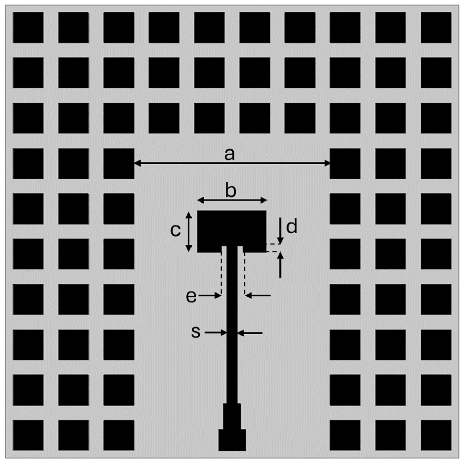
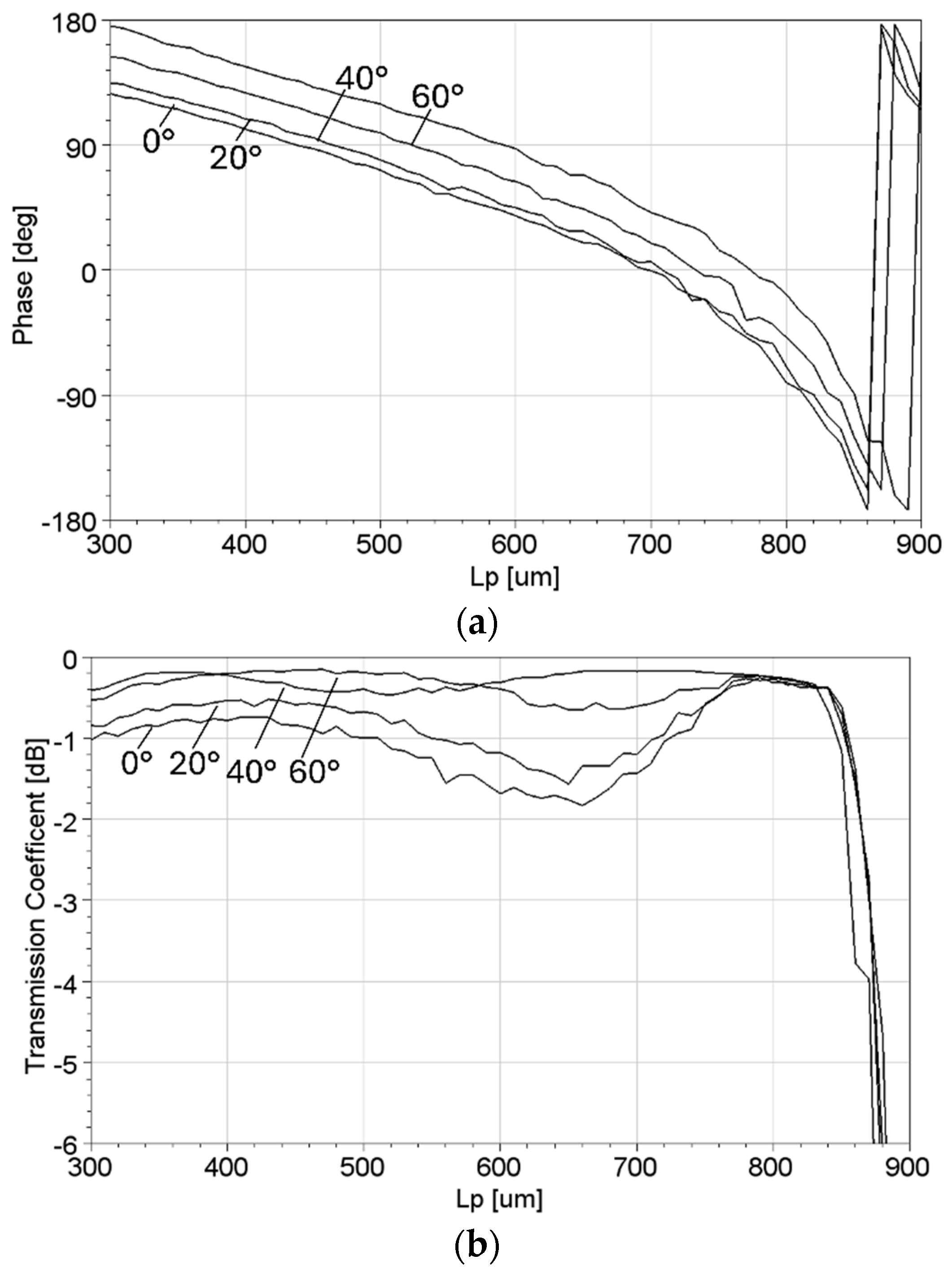
2.2. Transmit Array Unit Cell
3. Analytical Model
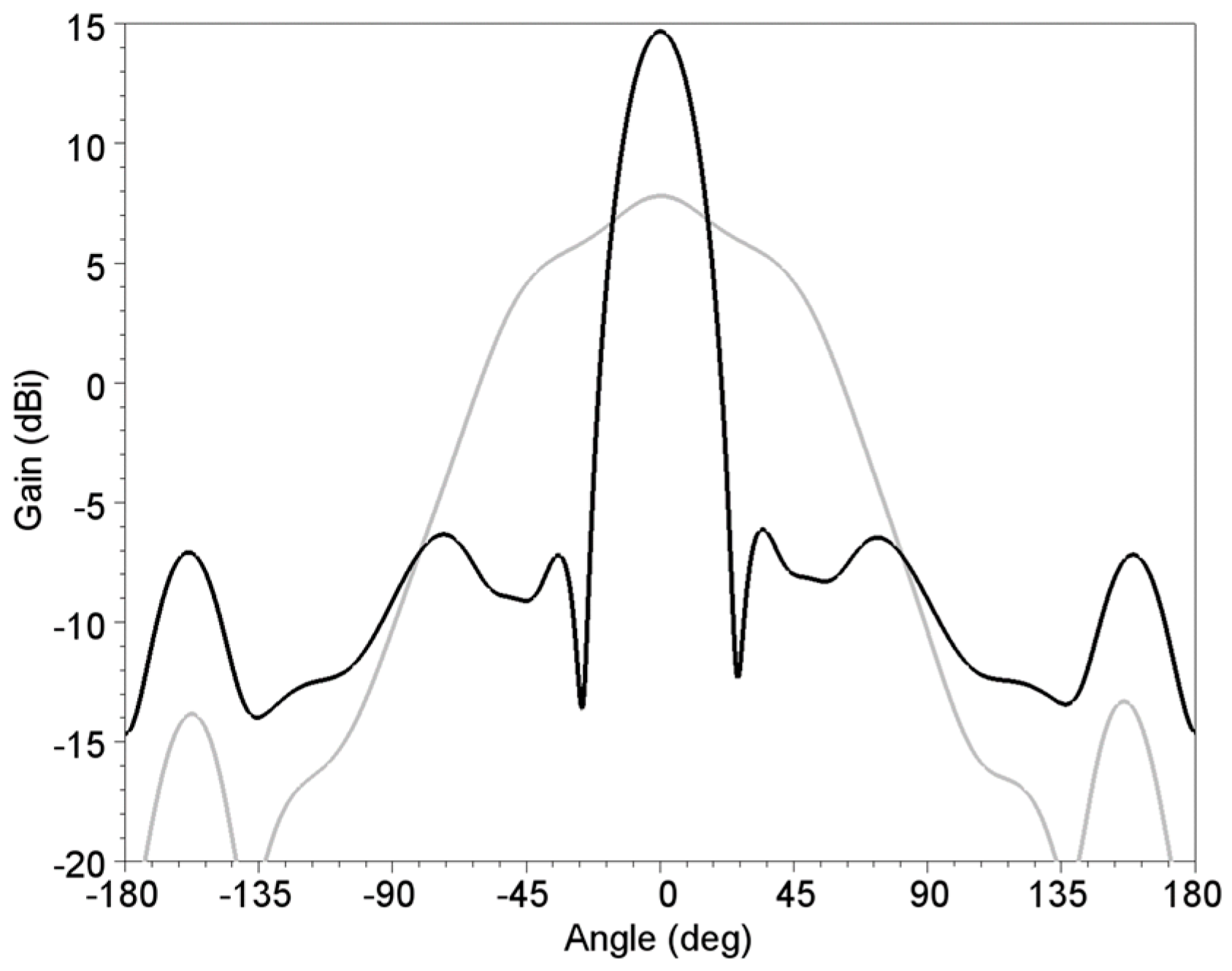
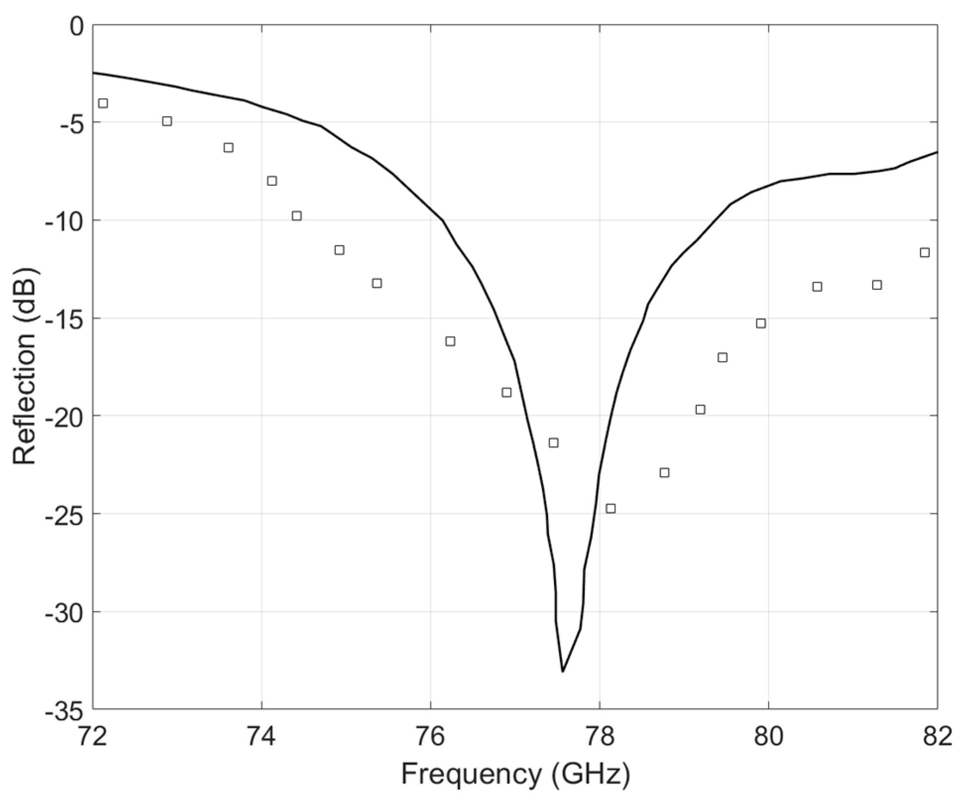
4. Results
5. Discussion
6. Conclusions
Author Contributions
Funding
Data Availability Statement
Conflicts of Interest
References
- Hasch, J.; Topak, E.; Schnabel, R.; Zwick, T.; Weigel, R.; Waldschmidt, C. Millimeter-Wave Technology for Automotive Radar Sensors in the 77 GHz Frequency Band. IEEE Trans. Microw. Theory Tech. 2012, 60, 845–860. [Google Scholar] [CrossRef]
- Arnieri, E.; Boccia, L.; Amendola, G.; Glisic, S.; Mao, C.; Gao, S.; Rommel, T.; Penkala, P.; Krstic, M.; Yodprasit, U.; et al. An Integrated Radar Tile for Digital Beamforming X-/Ka-Band Synthetic Aperture Radar Instruments. IEEE Trans. Microw. Theory Tech. 2019, 67, 1197–1206. [Google Scholar] [CrossRef]
- Menzel, W.; Moebius, A. Antenna Concepts for Millimeter-Wave Automotive Radar Sensors. Proc. IEEE 2012, 100, 2372–2379. [Google Scholar] [CrossRef]
- Arnieri, E.; Greco, F.; Boccia, L.; Amendola, G. A Reduced Size Planar Grid Array Antenna for Automotive Radar Sensors. IEEE Antennas Wirel. Propag. Lett. 2018, 17, 2389–2393. [Google Scholar] [CrossRef]
- Xu, J.; Hong, W.; Zhang, H.; Wang, G.; Yu, Y.; Jiang, Z.H. An Array Antenna for Both Long- and Medium-Range 77 GHz Automotive Radar Applications. IEEE Trans. Antennas Propag. 2017, 65, 7207–7216. [Google Scholar] [CrossRef]
- Porter, B.; Rauth, L.; Mura, J.; Gearhart, S. Dual-polarized slot-coupled patch antennas on Duroid with teflon lenses for 76.5-GHz automotive radar systems. IEEE Trans. Antennas Propag. 1999, 47, 1836–1842. [Google Scholar] [CrossRef]
- Saleem, M.K.; Vettikaladi, H.; Alkanhal, M.A.S.; Himdi, M. Lens Antenna for Wide Angle Beam Scanning at 79 GHz for Automotive Short Range Radar Applications. IEEE Trans. Antennas Propag. 2017, 65, 2041–2046. [Google Scholar] [CrossRef]
- Yeap, S.B.; Qing, X.; Chen, Z.N. 77-GHz Dual-Layer Transmit-Array for Automotive Radar Applications. IEEE Trans. Antennas Propag. 2015, 63, 2833–2837. [Google Scholar] [CrossRef]
- Park, Y.J.; Herschlein, A.; Wiesbeck, W. Offset cylindrical reflector antenna fed by a parallel-plate Luneburg lens for auto-motive radar applications in mm-wave. IEEE Antennas Propag. Soc. Int. Symp. 2002, 4, 588–591. [Google Scholar]
- Pozar, D. Flat lens antenna concept using aperture coupled microstrip patches. Electron. Lett. 1996, 32, 2109–2111. [Google Scholar] [CrossRef]
- McGrath, D. Planar three-dimensional constrained lenses. IEEE Trans. Antennas Propag. 1986, 34, 46–50. [Google Scholar] [CrossRef]
- Popovic, D.; Popovic, Z. Multibeam antennas with polarization and angle diversity. IEEE Trans. Antennas Propag. 2002, 50, 651–657. [Google Scholar] [CrossRef]
- Xi, J.; Xiao, F.; Wang, H. Comparative study on the reliability of QFN and AAQFN packages. In Proceedings of the 2014 15th International Conference on Electronic Packaging Technology, Chengdu, China, 12–15 August 2014; pp. 959–9620. [Google Scholar] [CrossRef]
- Li, L. Reliability modeling and testing of advanced QFN packages’. In Proceedings of the 2013 IEEE 63rd Electronic Components and Technology Conference, Las Vegas, NV, USA, 28–31 May 2013; pp. 725–730. [Google Scholar] [CrossRef]
- Lu, A.; Xie, D.; Shi, Z.; Ryu, W. Electrical and thermal modelling of QFN packages. In Proceedings of the 3rd Electronics Packaging Technology Conference (EPTC 2000) (Cat. No.00EX456), Singapore, 7 December 2000; pp. 352–356. [Google Scholar] [CrossRef]
- U.S. Chip Packaging with Mil-Spec Precision. Available online: https://semiengineering.com/u-s-chip-packaging-with-mil-spec-precision/ (accessed on 29 September 2022).
- Greco, F.; Boccia, L.; Amendola, G.; Arnieri, E. Design of an in-package transmit-array for automotive applications:preliminary results. In Proceedings of the 2022 Microwave Mediterranean Symposium (MMS), Pizzo Calabro, Italy, 9–13 May 2022; pp. 1–4. [Google Scholar] [CrossRef]
- Mustacchio, C.; Boccia, L.; Arnieri, E.; Amendola, G. A Gain Levelling Technique for On-Chip Antennas Based on Split-Ring Resonators. IEEE Access 2021, 9, 90750–90756. [Google Scholar] [CrossRef]
- Zaman, M.I.; Hamedani, F.T.; Amjadi, H. A New EBG structure and its application on microstrip patch antenna. In Proceedings of the 2012 15 International Symposium on Antenna Technology and Applied Electromagnetics, Toulouse, France, 25–28 June 2012; pp. 1–3. [Google Scholar] [CrossRef]
- Sravya, R.V.; Kumari, R. Gain enhancement of patch antenna using L-slotted mushroom EBG. In Proceedings of the 2018 Conference on Signal Processing And Communication Engineering Systems (SPACES), Vijayawada, India, 4–5 January 2018; pp. 37–40. [Google Scholar] [CrossRef]
- Neo, C.; Lee, Y.H. Patch antenna enhancement using a mushroom-like EBG structures. In Proceedings of the 2013 IEEE Antennas and Propagation Society International Symposium (APSURSI), Orlando, FL, USA, 7–13 July 2013; pp. 614–615. [Google Scholar] [CrossRef]
- Sievenpiper, D. High-Impedance Electromagnetic Surfaces. Ph.D. Thesis, University of California, Los Angeles, CA, USA, 1999. [Google Scholar]
- Plaza, E.; Leon, G.; Loredo, S.; Las-Heras, F. A Simple Model for Analyzing Transmitarray Lenses. IEEE Antennas Propag. Mag. 2015, 57, 131–144. [Google Scholar] [CrossRef]
- Arnieri, E.; Amendola, G.; Boccia, L. Stacked shorted circular patch antenna in SIW technology for 60-GHz band arrays. In Proceedings of the 2017 IEEE International Symposium on Antennas and Propagation USNC/URSI National Radio Science Meeting, San Diego, CA, USA, 9–14 July 2017; pp. 2675–2676. [Google Scholar] [CrossRef]
- Clemente, A.; Dussopt, L.; Sauleau, R.; Potier, P.; Pouliguen, P. Multiple feed transmit-array antennas with reduced focal distance. In Proceedings of the 2012 9th European Radar Conference, Amsterdam, The Netherlands, 30 October–1 November 2012; pp. 500–503. [Google Scholar]
- Kaouach, H.; Dussopt, L.; Lanteri, J.; Koleck, T.; Sauleau, R. Wideband Low-Loss Linear and Circular Polarization Transmit-Arrays in V-Band. IEEE Trans. Antennas Propag. 2011, 59, 2513–2523. [Google Scholar] [CrossRef]
- Vorobyov, A.; Fourn, E.; Sauleau, R.; Baghchehsaraei, Z.; Oberhammer, J.; Chicherin, D.; Raisanen, A. Iris-based 2-bit waveguide phase shifters and transmit-array for automotive radar applications. In Proceedings of the 2012 6th European Conference on Antennas and Propagation (EUCAP), Prague, Czech Republic, 26–30 March 2012; pp. 3711–3715. [Google Scholar] [CrossRef]
- Bu, D.; Qu, S. Magneto-electric dipole antenna array for 77 GHz automotive radar. IET Microw. Antennas Propag. 2024, 18, 96–105. [Google Scholar] [CrossRef]


Disclaimer/Publisher’s Note: The statements, opinions and data contained in all publications are solely those of the individual author(s) and contributor(s) and not of MDPI and/or the editor(s). MDPI and/or the editor(s) disclaim responsibility for any injury to people or property resulting from any ideas, methods, instructions or products referred to in the content. |
© 2024 by the authors. Licensee MDPI, Basel, Switzerland. This article is an open access article distributed under the terms and conditions of the Creative Commons Attribution (CC BY) license (https://creativecommons.org/licenses/by/4.0/).
Share and Cite
Greco, F.; Arnieri, E.; Amendola, G.; De Marco, R.; Boccia, L. A 77 GHz Transmit Array for In-Package Automotive Radar Applications. Telecom 2024, 5, 792-803. https://doi.org/10.3390/telecom5030040
Greco F, Arnieri E, Amendola G, De Marco R, Boccia L. A 77 GHz Transmit Array for In-Package Automotive Radar Applications. Telecom. 2024; 5(3):792-803. https://doi.org/10.3390/telecom5030040
Chicago/Turabian StyleGreco, Francesco, Emilio Arnieri, Giandomenico Amendola, Raffaele De Marco, and Luigi Boccia. 2024. "A 77 GHz Transmit Array for In-Package Automotive Radar Applications" Telecom 5, no. 3: 792-803. https://doi.org/10.3390/telecom5030040
APA StyleGreco, F., Arnieri, E., Amendola, G., De Marco, R., & Boccia, L. (2024). A 77 GHz Transmit Array for In-Package Automotive Radar Applications. Telecom, 5(3), 792-803. https://doi.org/10.3390/telecom5030040