1. Introduction
With the rapid development of the aerospace industry, there has been an increasing demand for the accuracy control and rapid response capabilities of spacecraft attitude control systems in recent years. The reaction flywheel, a critical component of satellite attitude control systems, has been used extensively in these systems due to its rapid response, high accuracy, stability, and energy efficiency. Its primary function is to control the motor speed of the reaction flywheel and provide angular momentum output to regulate satellite attitude.
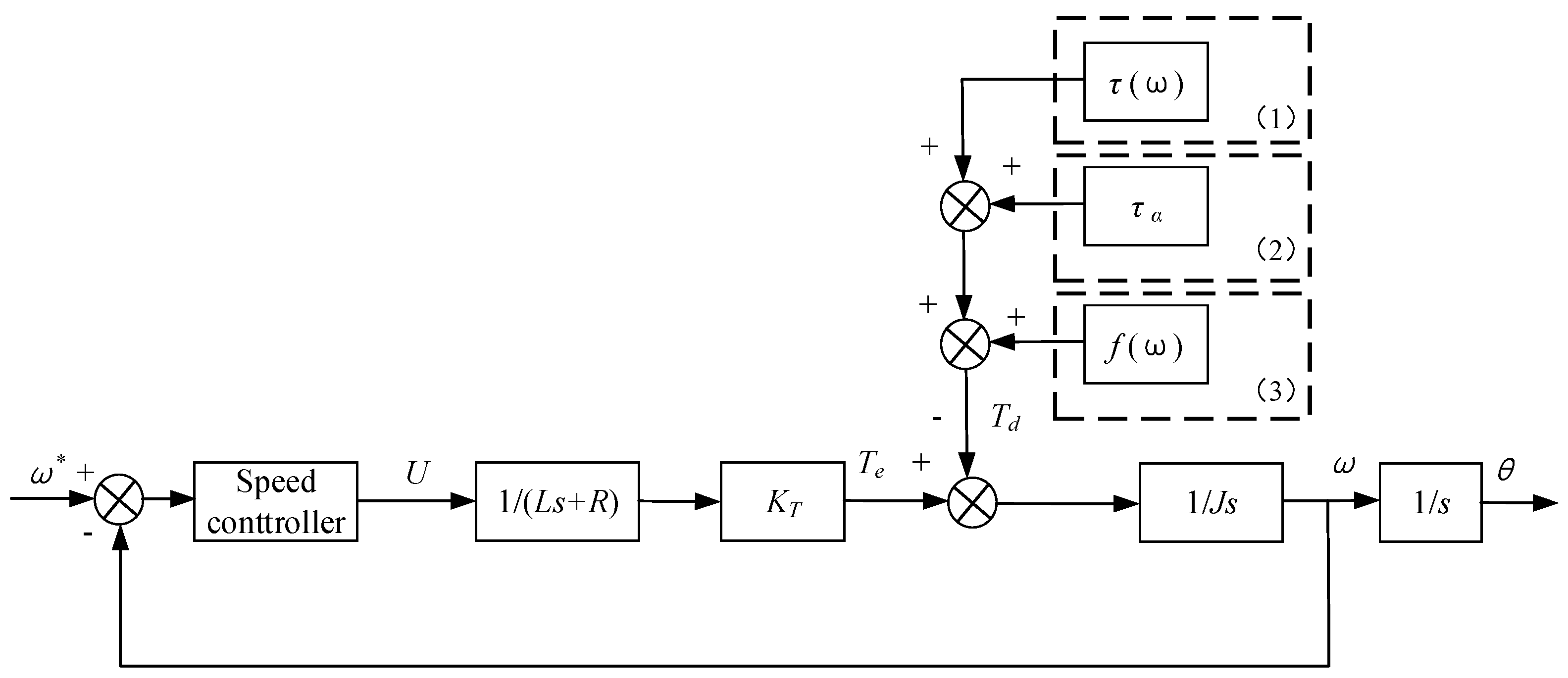
The reaction flywheel generally consists of a high-speed motor, bearings, and a control circuit. In engineering applications, it is essential to ensure that the high-speed motor and bearings exhibit good servo performance. However, various disturbances, which affect the high-speed motor and bearings, degrade the dynamic characteristics of the reaction flywheel system markedly. Disturbances such as friction torque, cogging torque, magnetic flux distortion, current ripple, and bearing noise torque [
1] mainly impact the accuracy of reaction flywheel speed control. When the high-speed rotor of the reaction flywheel rotates, velocity fluctuations are generated and transferred to the spacecraft, ultimately affecting the spacecraft’s attitude control performance. Therefore, it is necessary to classify, analyze, and suppress these disturbances accurately to achieve high-accuracy velocity tracking control.
Currently, proportional–integral–derivative (PID) control is used widely in various motor drive systems. As a simple control method that provides good performance, PID controllers are not ideal for speed control of reaction flywheels, especially in the context of without using expensive bearings that have been strictly screened. To overcome disturbances and improve the speed control accuracy of reaction flywheels, more advanced control methods are required. Reference [
2] has described disturbance estimation technology in the presence of parameter uncertainty and disturbance forces in detail. The use of a disturbance observer can enhance the motor speed control performance. Reference [
3] employs a Linear Quadratic Regulator (LQR) with an observer, assuming the disturbance is periodic. Reference [
4] employs feedback linearization and an extended high-gain observer to achieve high accuracy and fast response in the speed control of permanent magnet synchronous motors (PMSM). Reference [
5] designs a disturbance observer that considers various disturbances, including cogging torque, load torque, friction torque, measurement error effects, dead time effects, and parameter disturbances. Most of these papers present experimental/simulation results showcasing the performance of these approaches.
Active disturbance rejection control (ADRC) is a fully-based control design method that builds upon the essence of PID control technology and incorporates achievements from modern control theory. The fundamental concept of ADRC involves treating the system’s nonlinear and unmeasurable disturbances as lumped unknown signals without any specific state variable structure, thereby simplifying the task of state and disturbance estimation [
6]. By effectively estimating the sum of various disturbances in real time, their influence on the system’s closed loop is mitigated. The extended observer is a common tool for real-time disturbance estimation.
Motivated by these aforementioned observations, this paper focuses on the high-accuracy velocity control challenge of reaction flywheel systems subjected to multiple disturbances. The main contributions and enhancements of this paper are as follows:
(1) ADRC is introduced to enhance the reaction flywheel system’s anti-disturbance capability by integrating an extended state observer, which can be modeled as an exogenous system, while unmodeled disturbances are treated as a lumped term and estimated by the extended state observer.
(2) Based on the extended state observer, an ADRC system is designed. Compared to other control algorithms, this scheme enables the reaction flywheel system state to converge to the equilibrium point in finite time and achieves disturbance rejection. The corresponding composite anti-disturbance control algorithm is easy to implement due to the straightforward adjustment of controller parameters.
(3) The proposed control algorithm ensures a satisfactory reaction flywheel control performance even in the presence of different types of disturbances with relatively large amplitudes.
The remainder of this paper is organized as follows.
Section 2 presents the problem formulation. The design process of the proposed ARRC system is outlined in
Section 3.
Section 4 verifies the effectiveness of the proposed control scheme through comparative simulation tests. In
Section 5, the proposed control scheme’s effectiveness is verified through real tests. Finally,
Section 6 concludes this paper.
3. Control Law Design
In this section, the active disturbance rejection control (ADRC) controller for the reaction flywheel is designed, and an extended state observer is developed to estimate the reaction flywheel’s speed and total disturbances. Through modeling and derivation of mathematical formulas, the convergence of the estimation error for the extended state observer is proven. Finally, a reaction flywheel speed controller with feedforward compensation for total disturbances is designed, and the controller’s stability is demonstrated.
3.1. Design of Current Loop Controller
A proportional–integral (PI) controller is utilized for the current loop, yielding favorable outcomes. The desired control bandwidth for the current loop is denoted as
ωc, and the parameter configuration for the current PI controller is expressed as shown in Equation (4):
where
represents the proportional gain coefficient of the controller,
represents the integral gain coefficient of the controller, while
Rs represents Terminal resistance and
L represents Terminal inductance.
At this juncture, the zero point of the current controller can nullify the poles of the motor model. The current loop is adjusted into a stable first-order low-pass system, with its closed-loop transfer function expressed as demonstrated in Equation (5):
3.2. Design of Extended State Observer
In this section, we will design an extended state observer to estimate the velocity and total disturbances of the reaction flywheel. Through modeling and mathematical formula derivation, we will demonstrate the convergence of the estimation error e1, …, en of the extended state observer. Finally, we will design a reaction flywheel speed controller u(t) with feedforward compensation and establish the stability of the controller.
The ADRC controller employs a third-order linear extended state observer to dynamically monitor the speed of the reaction flywheel motor and the overall disturbances of the system in real time. The angular position of the reaction flywheel rotor is denoted as state
x1, the flywheel’s velocity is represented by state
x2, the cumulative disturbances within the system are captured as state
x3, and the derivative of
x3 is recorded as
a(t):
The third-order extended state observer is designed as shown in Equation (7):
where,
z1,
z2,
z3 are the observed values of reaction flywheel rotor position, speed, and total value of disturbances, respectively.
β1,
β2,
β3 are error gain values of each order. We define the matrix
A and following vectors in Equation (8):
Then Equation (7) can be rewritten as in Equation (9):
System disturbances can be rewritten as in Equation (10):
The reaction flywheel motor speed state feedback control law adopts PI plus feedforward control. The proportional control parameter is
Kp, the integral control parameter is
Ki, the given command speed is
x0, the difference between the speed command and the speed is
x0–
x2, and the
x0–x2 integral is set as
xc. The state feedback control law is designed as in Equation (11):
The observer that includes the control input is expressed by Equation (12):
We define the matrix
A′, matrix
B′, and the following vectors as presented in Equation (13):
Subsequently, Equation (12) can be rewritten as shown in Equation (14):
System disturbances can be redefined using Equation (15):
Next, we analyze the performance of the disturbances’ observer. Based on the error dynamic equation of the disturbance observer given by Equations (16) and (17):
We select suitable values for
β1,
β2,
β3, and
Kp to ensure the stability of
A0 to be Hurwitz; for any positive definite symmetric matrix
Q > 0, there exists a unique positive definite symmetric matrix
P > 0, as demonstrated in Equation (18):
Choose the Lyapunov function as shown in Equation (19):
Differentiate Equation (19) and substitute Equation (18) into it to yield:
Let
γ1 represent the minimum eigenvalue of the matrix. Based on Equation (20), we derive Equation (21):
The choice of Q determines its minimum eigenvalue γ1. By selecting appropriate values for β1, β2, β3, and Kp, rapid convergence can be achieved. Thus, the designed disturbances’ observer can configure the characteristic roots of the disturbance observer system to desired positions by choosing suitable parameters, achieving swift convergence of observation errors.
3.3. Design of Reaction Flywheel Speed Controller
The observed disturbances are compensated through feedforward control. The control system block diagram of the reaction flywheel is depicted in
Figure 4.
Reasonably design β1, β2, β3, Kp, Ki parameters, and utilize MATLAB to calculate the model transfer function. The MATLAB commands are as follows:
[a,b,c,d] = linmod(‘Copy_of_test1_modified20211126’);
sys = tf(minreal(ss(a,b,c,d)));
The closed-loop system transfer function obtained is:
With roots of the denominator’s characteristic polynomial in the left half of the complex plane, the step response is shown in
Figure 5. It can be observed that the reaction flywheel control system designed based on ADRC is stable and exhibits rapid convergence.
4. Simulation Results and Analysis
In this section, we compare the speed tracking and disturbance suppression performance of the reaction flywheel system using both PID controller and ADRC controller through simulations. The simulation parameters for the reaction flywheel are consistent with the actual system, as shown in
Table 1.
As depicted in
Figure 6 and
Figure 7, we simulate the speed-tracking capabilities of the two controllers. With a fixed speed command, it can be observed from the flywheel’s speed response curves that the response rates of the PID controller and the ADRC controller are essentially the same, but the PID controller exhibits a significant overshoot. On the other hand, the ADRC controller shows minimal overshoot, thereby effectively enhancing the system’s ability to rapidly track the speed command.
In the PID controller,
Kp = 5,
Ki = 0.05,
Kd = 0. As shown in
Figure 4, in the ADRC controller,
Kp = 5,
Ki = 0.05,
Kd = 0, which are the same as the control parameters in the PID controller. By using the same control parameters, the ADRC controller is capable of suppressing overshoot and ensuring response speed by compensating for various disturbances, whereas the PID controller often compromises on overshoot suppression and response speed.
Subsequently, different types of bearing noise torque are simulated as disturbance inputs, and the suppression effects of both the PID controller and ADRC controller on different bearing noise torques are compared.
As shown in
Figure 8, particle pollution or damage occurs on the steel ball within the flywheel bearing. The disturbance is depicted in
Figure 8i with an amplitude of 4~5 mNm, which is a periodic signal. When the disturbance arises, if the PID controller is employed as shown in
Figure 8ii, the reaction flywheel’s speed will drop by about 5 rpm. Conversely, with the use of the ADRC controller as shown in
Figure 8iii, the speed fluctuation remains within 0.5 rpm. The disturbance suppression effect of the ADRC controller surpasses that of the PID controller by approximately an order of magnitude.
As illustrated in
Figure 9, an instantaneous stop of the bearing cage occurs within the reaction flywheel bearing. The disturbance simulation is depicted in
Figure 9i, with an amplitude of 4~5 mNm, representing a non-periodic signal. When a disturbance torque emerges, if the PID speed controller is utilized, as shown in
Figure 9ii, the reaction flywheel’s speed will decrease by approximately 5 rpm. Conversely, with the utilization of the ADRC speed controller, as shown in
Figure 9iii, the speed fluctuation remains within 0.5 rpm. The disturbance suppression effect of the ADRC controller surpasses that of the PID controller by about an order of magnitude.
As illustrated in
Figure 10, the simulation curve of disturbances generated by the dynamic characteristics of the bearing lubricant is depicted in
Figure 10i, with an amplitude of 4~5 mNm, constituting a non-periodic signal. In the presence of this disturbance, if the PID speed controller is utilized as shown in
Figure 10ii, the reaction flywheel will experience a speed reduction corresponding to the disturbance torque, leading to a maximum speed error of 5 rpm. Alternatively, when the ADRC speed controller is employed, as demonstrated in
Figure 10iii, the speed fluctuation remains within 0.5 rpm. The disturbance suppression effect of the ADRC controller on the dynamic characteristics of bearing lubricant is notably superior to that of the PID controller.
With the same control parameters, the ADRC controller can adaptively suppress different types of disturbances by compensating for various disruptions, while the PID controller is unable to adaptively suppress different types of disturbances.
5. Experimental Results
The practical performance of the proposed ADRC controller is assessed through two experiments. The first experiment aims to demonstrate the speed-tracking capability of the proposed ADRC controller. The second experiment tests the disturbance rejection ability of the proposed ADRC controller. Both experiments were compared with differences in control effects between the PID controller and ADRC controller. The parameters of the reaction flywheel motor used are consistent with the simulation experiments, as shown in
Table 1.
In order to obtain optimal speed controller parameters
β1,
β2,
β3,
Kp, and
Ki, several experiments were conducted. In these experimental results, we only selected parameters with an overshoot ≤ 2%, effective disturbance suppression, and without oscillation [
11,
12].
The control algorithm is based on the reaction flywheel control system of the stm32f103 ARM chip. The reaction flywheel control circuit board is depicted in
Figure 11 and is installed within the reaction flywheel. The current of the reaction flywheel is measured using high-precision sampling resistors. The position of the reaction flywheel rotor is determined through a 4096PPR incremental encoder [
13,
14], which is directly mounted at the end of the motor shaft.
All speed data acquired during the experiment were measured utilizing dedicated testing equipment designed for reaction flywheel products.
Figure 12 presents a photograph of the experimental setup. The testing equipment encompasses a test computer, reaction flywheel testing software 2.0, power supply, and a multi-way flywheel switching device.
The black cube on the left side of
Figure 12 is the reaction flywheel where the maximum angular momentum is 600 mNms, maximum output torque is 40 mNm, and the speed control accuracy is 2 rpm (2σ). The mass of the reaction flywheel is 1400 ± 100 g, with 24~30 voltage power supply and 30 watts maximum power consumption.
5.1. Experiment 1
In Experiment 1, the change time of the speed command is 0.25 s, and each beat’s increment is 20 rpm. We compare the tracking effects of the PID controller and the ADRC controller.
Figure 13i displays the curves of the reference command signal
ωref, the actual speed
ωadrc of the ADRC controller, and the actual speed
ωPID of the PID controller. It can be observed that the ADRC controller can closely track the reference command signal, while the PID controller exhibits a significant overshoot.
Figure 13ii further illustrates the performance difference between the ADRC controller and the PID controller. During the process of tracking the speed command
ωref, the tracking error of the ADRC controller gradually decreases, and the speed stabilizes near the setpoint within 1 rpm, while the PID controller experiences noticeable overshoot and oscillation exceeds 10 rpm.
5.2. Experiment 2
In this experiment, the control effects of the ADRC controller and the PID controller are compared when the reaction flywheel runs at a constant speed and there are nonlinear and time-varying disturbances in the bearing. The reaction flywheel operates at a steady speed of 6000 rpm. In this scenario, the actual disturbance torque is significant, and the comparative effect is evident [
15]. As shown in
Figure 14, when the reaction flywheel runs at 6000 rpm using the PID controller, the flywheel experiences random speed loss, approximately 4–6 rpm. This phenomenon is similar to the one depicted in
Figure 8 from the previous simulation. The bearing noise torque may result from particle pollution or damage to the bearing steel ball. The PID controller is unable to effectively suppress such nonlinear and time-varying disturbances. As illustrated in
Figure 15, when the ADRC controller program is implemented on the same control circuit and the reaction flywheel runs at 6000 rpm, the control effect exhibits significant advantages. This outcome is consistent with the previous simulation effect, and the control accuracy can be maintained within 0.5 rpm.
Both experiments demonstrate that the proposed ADRC controller outperforms the PID controller in terms of tracking reaction flywheel speed commands and suppressing disturbances. The robustness of the proposed ADRC controller stems from its ability to estimate and eliminate the total disturbances within the control system. In Experiment 1, the disturbance is primarily attributed to friction torque, while in Experiment 2, the disturbance is primarily caused by bearing noise torque. The ADRC controller is capable of measuring disturbances and effectively suppressing them through feedforward compensation, yielding favorable control results.
6. Conclusions
This paper describes the design of a speed controller for a reaction flywheel based on ADRC. Compared to the PID controller, the ADRC-based controller achieves effective disturbance suppression and high-precision control of the flywheel speed through an extended state observer, particularly for disturbances from bearing friction torque and bearing noise torque. In scenarios where the reaction flywheel bearings are not rigorously selected, the control accuracy using a PID controller is difficult to maintain below 2 rpm. The fundamental reason is the trade-off between the rapid response characteristics of the flywheel and control precision. Increasing Kp can enhance rapid response characteristics but leads to increased overshoot; increasing Ki can improve control precision but worsens dynamic characteristics, and increasing Kd can enhance dynamic characteristics but reduces precision. The opposite is also true. However, with the ADRC control method proposed in this paper, using the extended state observer, disturbance from the flywheel bearing can be suppressed while achieving precise control of the flywheel speed. In the experiments from the previous section, the developed ADRC-based controller achieved rapid response characteristics better than 0.25 s and control accuracy better than 1 rpm.
In summary, theoretical analysis, mathematical simulation, and physical experiments collectively demonstrate the effectiveness of the ADRC controller in suppressing internal disturbances of the reaction flywheel bearing, improving speed control accuracy, and enhancing dynamic characteristics. In real-world applications, an ADRC-based control system approach can reduce the selection cost of reaction flywheel bearings and improve the pointing accuracy of satellite attitude control systems.


