Article

Task Location to Improve Human–Robot Cooperation: A Condition Number-Based Approach

by
Abdel-Nasser Sharkawy
1,2
1
Mechatronics Engineering, Mechanical Engineering Department, Faculty of Engineering, South Valley University, Qena 83523, Egypt
2
Mechanical Engineering Department, College of Engineering, Fahad Bin Sultan University, Tabuk 47721, Saudi Arabia
Automation 2023, 4(3), 263-290; https://doi.org/10.3390/automation4030016
Submission received: 14 August 2023 / Revised: 27 August 2023 / Accepted: 30 August 2023 / Published: 6 September 2023
(This article belongs to the Collection Smart Robotics for Automation)

Abstract

:
This paper proposes and implements an approach to evaluate human–robot cooperation aimed at achieving high performance. Both the human arm and the manipulator are modeled as a closed kinematic chain. The proposed task performance criterion is based on the condition number of this closed kinematic chain. The robot end-effector is guided by the human operator via an admittance controller to complete a straight-line segment motion, which is the desired task. The best location of the selected task is determined by maximizing the minimum of the condition number along the path. The performance of the proposed approach is evaluated using a criterion related to ergonomics. The experiments are executed with several subjects using a KUKA LWR robot to repeat the specified motion to evaluate the introduced approach. A comparison is presented between the current proposed approach and our previously implemented approach where the task performance criterion was based on the manipulability index of the closed kinematic chain. The results reveal that the condition number-based approach improves the human–robot cooperation in terms of the achieved accuracy, stability, and human comfort, but at the expense of task speed and completion time. On the other hand, the manipulability-index-based approach improves the human–robot cooperation in terms of task speed and human comfort, but at the cost of the achieved accuracy.

1. Introduction

Human–robot interaction (HRI) is one of the most investigated research fields in robotics. HRI has significant benefits when executing a cooperative task in comparison with the guidance offered by a teach pendant or simple robotic automation. On this point, it is important to differentiate between the terms “human–robot cooperation or collaboration” and “human–robot communication”. Human–robot cooperation or collaboration (HRC) [1,2] is the research area aimed at combining the capabilities of robots with human skills in a complementary manner. Robots can assist humans by increasing their capabilities in terms of precision, speed, and force. In addition, robots can reduce the stress and the tiredness of the human operator and thus improve their working conditions. Humans can contribute to cooperation in terms of experience, knowledge about executing a task, intuition, easy learning, and adaptation, and through easily understanding control strategies. Many tasks require both a high human-operator flexibility and robot payload ability [3], for example, in the manipulation of heavy or bulky objects and the assembly of heavy parts. Therefore, cooperative manipulation could help complete these tasks more easily and reduce human burden. Collaboration and cooperation are often used interchangeably. However, collaboration differs from cooperation as it includes a shared goal and joint action, where both parties’ success depends on one another [4,5]. In human–robot communication [6], the robot receives commands from the human operator to operate on a workspace via speech or gestures; this is called one-way communication. Two-way communication works using AR techniques [7], where the information is transferred to the robot by the human operator via vision sensors. In a co-manipulation task, finding the best configuration of the human arm and the manipulator is very important for improving the HRI, which is the main topic of the current paper.
In robotics, condition numbers are used as a tool to measure the degree of dexterity. The condition number of the Jacobian matrix is used to show the kinematic isotropy of the manipulator. Isotropic configuration has a number of advantages such as good servo accuracy and avoiding singularity [8]. As the human arm can be modeled as a kinematic chain, the condition number is used in ergonomics, separate from other criteria, to evaluate the human arm motion.

1.1. Related Work

Ergonomics’ investigations have demonstrated that human arm movements have more advantages in specific directions than in other directions, both as far as comfort and speed, because of the anatomical characteristics of the hand−arm complex. In [9,10], Meulenbroek and Thomassen demonstrated the movement preference in specific directions on the horizontal plane for repetitive line-drawing tasks. The authors of [11,12,13] presented similar directional preferences using a free-stroke drawing task. Reviewing the potential sources of movement cost, Dounskaia and Shimansky deduced that the movements of the multi-joint human arm are characterized by the so-called “trailing joint control pattern”, which reduces the joint’s coordination neural effort [14]. Movement in a diagonal direction has a profound effect in terms of speed. Schmidtke and Stier ([15]; quoted in Sanders and McCormick [16], p. 290) and Levin et al. [17] demonstrated that the fastest movements occurred along the right diagonal, whereas the slowest movements occurred along the left diagonal. In accordance with the classic theories of motor control, the latter findings reflect a speed−accuracy trade-off, predicting that faster movements are executed with lower accuracy, and vice versa (see [18,19] for a review). More recent motor control models have increased the possibility of a cost−benefit trade-off between the foreseeable muscular effort and the expected rewards [20,21,22,23]. The discrepancies between the required movement orientations and actual corresponding ones are more noticeable with large human arm displacements. It is very important that these findings are incorporated and used as evaluation criteria when designing human–robot interactive tasks.
Previous HRI research has highlighted safety aspects and the implementation of control algorithms. In this paper, we present the ergonomics aspect. Several indices were discussed in [13] to show the factors that influence the choice of movement directions in order to optimize the human arm motor behavior. The interaction torque index at the shoulder and the elbow is used for regulating the interaction torque with muscular control for a goal-oriented movement. The inertial resistance index is used to evaluate the relationship between the force applied at the endpoint and the endpoint acceleration caused because of the inertia of the arm segment. The minimum sum of the squared torque is a simplified representation of the energetic cost associated with the production of each stroke relative to the maximum energetic cost of all the strokes. Other indices include the minimization of jerk, the torque change, the maximization of the kinematic manipulability index [13], and the condition number [24].
The manipulability index [25] presents the ability of the system to perform a high TCP velocity motion with a low overall joint velocity. In our previous paper [26], the evaluation of the closed kinematic chain (CKC) system configuration was based on the manipulability index. Firstly, the condition number is used as an index to describe the accuracy/dexterity of the robot. Secondly, it is used to describe the closeness of the pose to the singularity [8,27]. The condition number for manipulators is calculated in [25,28], and for parallel manipulators, it is presented in [27,29].
The condition numbers in robotics manipulator are widely used in optimization procedures. In [24], Shabnam Khatami used the global condition number in a minimax optimization problem. In his work, the genetic algorithm was used to optimize the minimax problem and to find the optimal design parameters such as the link lengths of the best isotropic robot configurations at optimal working points of the end-effector; it has since been implemented globally to optimize the entire robot workspace. In [30], condition number minimization was presented for functionally redundant serial manipulators. In [31], a new global condition number was presented in order to quantify the configuration-independent isotropy of the robot’s Jacobian or mass matrix. A new discrete global optimization algorithm was proposed to optimize either the condition number or some local measure, without placing any conditions on the objective function. The algorithm was used to choose the optimum geometry for a 6-DOF Stewart Platform. In [32], Ayusawa et al. proposed a novel method for generating persistently exciting trajectories by using optimization together with an efficient gradient computation of the condition number, with respect to the joint trajectory parameters. Their method was validated by generating several trajectories for the humanoid robot HRP-4. An approach to the parameterization of robot excitation trajectories was presented in [33]. This approach allowed for the generation of robot experiments that were robust with respect to measurement inaccuracies. This corresponded to small condition numbers for a regression matrix, defined by the set of dynamic equations.
From this discussion, we can conclude that the condition number is a well-known metric used in robotics. In addition, the best configuration for both the human arm and the manipulator based on a condition number, as well as its effect on improving the HRI, have not yet been researched.

1.2. The Main Contribution

This manuscript proposes an approach to improve the performance in the human–robot co-manipulation task. This manuscript is considered an extension of our previous work [34], which showed only the simulation part of the work. In this task, the human operator grasped the robot handle, which formed a closed kinematic chain (CKC) comprised of the human arm and the admittance-controlled manipulator. The human arm was modeled as a 7-DoF combined with the 7-DoF manipulator; therefore, the system was modeled as 14-DoF CKC. A task-based measure was formulated for this CKC by minimizing the condition number of the CKC along the path. This task-based measure was maximized using a genetic algorithm (GA) to determine the suboptimal location of the path in the workspace of the CKC considered here. The co-manipulation performance was evaluated experimentally using four criteria related to the ergonomics criteria, where the human arm was not free as it usually is in ergonomics studies, but it guided the manipulator via an admittance control.
The KUKA LWR robot was used to execute the experiments and the proposed approach was investigated and evaluated with the help of 15 subjects. The results prove that the proposed approach effectively improved HRI and, particularly, ergonomics. Finally, a comparison between the current proposed approach and the previous approach where the task performance criterion was based on the CKC manipulability index [26] was included.
This manuscript is organized as follows. In Section 2, an overview of the proposed approach is presented, as well as its following main steps. In Section 3, the closed kinematic chain of the human arm and the manipulator is presented. Section 4 introduces the formulation of the proposed task-based measure as well as the variable constraints of the considered optimization problem that was solved using GA. In Section 5, the experimental work and an evaluation of the performance using the proposed criteria are presented. Finally, Section 6 provides concluding remarks and some future works.

2. The Condition Number-Based Approach

This paper presents an approach to evaluate and improve the performance of the HRI in a co-manipulation task. The robot base as well as the human operator are in a fixed relative position/orientation and have a common workspace. The main steps followed for the procedure in our proposed approach are discussed as follows.
(1)
Modeling the human arm and manipulator in a co-manipulation task as a CKC.
In this step, the human arm and the manipulator in the co-manipulation task are modeled as a CKC, where either the human arm or the manipulator is modeled as a 7-DOF open kinematic chain. The Denavit–Hartenberg (DH) parameters of the human arm are determined based on the anthropometric data of the male 95th percentile. In addition, the human arm motion constraints depend on the ergonomic limitations for the marginal comfort range of joint motions [35]. In the case of the manipulator, the DH parameters and the constraints are determined by the specifications of the robot. This step is discussed in detail in Section 3.
(2)
The suboptimal location of the task is determined.
In this step, the proposed method starts to determine the best location of the task. The task’s best location is found by determining the location in the common workspace, where the minimum value of the condition number of the CKC is maximized by taking into consideration the constraints of both robot and human arm using a GA. This step is discussed in detail in Section 4.
(3)
Experimental evaluation of the proposed approach.
In this step, the determined task location of the best configuration of both the human arm and the robot are defined in the experimental set-up. The KUKA LWR robot, which is a collaborative robot, is used for the experiments. The human hand guides the robot end-effector via the admittance controller along three straight-line segments; one straight-line segment is the determined best direction, whereas the other two are randomly directed. This is performed for comparison. The tasks are executed by 15 subjects and the motion measurements are obtained by KUKA robot controller (KRC) and by an external force sensor attached to the robot end-effector. Criteria are used related to the ergonomics criteria for evaluating the task performance as follows: the required human effort to guide the robot end-effector, the task completion time, the position error between the straight-line segment, and the actual position of the robot end-effector; and finally, the oscillations occur during the movement. In addition, a questionnaire is given to each subject to collect qualitative information about the required human effort, the oscillations/accuracy experienced, and finally, the human comfort level. This step is discussed and presented in detail in Section 5.

3. Modeling of the Closed Kinematic Chain—Step 1

The human operator grasps the robot handle, which is attached to the robot end-effector. Therefore, a CKC is formulated, and its kinematic model is developed. In this CKC, the human arm is modeled as a 7-DOF manipulator, consisting of revolute joints, as follows: three-DOF for the shoulder, one-DOF for the elbow, and 3-DOF (spherical wrist) for the wrist. Figure 1 presents the model of the human arm in a fully extended case. The DH parameters used for modeling the human arm are determined based on the 95th percentile of the males [36]. The DH parameters for the human arm as well as the KUKA LWR are presented in Table 1. In the table, d is the link offset, a is the link length, α is the twist angle, and θ _ r R 7 × 1 and θ _ h R 7 × 1 are the joints angle vectors, respectively, for the KUKA LWR and for the human arm.
The joints’ limits θ _ r m i n , θ _ r m a x for the KUKA LWR model as referred in [37], in terms of the radians’ angles. These limits are given as:
θ _ r m i n = p i 1.06 p i 1.5 p i 1.06 p i 1.5 p i 1.06 p i 1.5 p i 1.06
θ _ r m a x = p i 1.06 p i 1.5 p i 1.06 p i 1.5 p i 1.06 p i 1.5 p i 1.06
The human arm model respects the ergonomic limitations for the marginal comfort range [35]. The marginal comfort level is located between the slightly poor comfort level and the moderate comfort level. These ergonomic limitations are obtained as:
θ _ h m i n = 0.52 0.44 0.24 0 0.87 1 1.85
θ _ h m a x = 1.57 1.27 1.5 2.5 0.5 1.3 1.52
The CKC is formulated since the human operator grasps the robot handle, where the common Cartesian velocity v _ = r ˙ _ , ω _ R 6 × 1 can be obtained by [28]:
v _ = J h θ ˙ _ h = J r θ ˙ _ r v _ v _ r = v _ h
In Equation (1), r and h express the KUKA LWR model and the human arm, respectively. J r R 6 × 7 and J h R 6 × 7 are the Jacobian matrix for the KUKA LWR and the human arm, respectively. θ ˙ _ r , θ ˙ _ h R 7 × 1 are the joints’ velocities for the KUKA LWR and the human arm, respectively.
The Jacobian matrix of the CKC model J C K C R 12 × 14 by combining the two Jacobians J r , J h [38] is given by:
J r 0 0 J h θ ˙ _ r θ ˙ _ h = J C K C θ ˙ _ r θ ˙ _ h = I 6 I 6 v _
Detailed information about the kinematics of the closed kinematic chain is presented in Appendix A.

4. Suboptimal Task Location Determination—Step 2

The desired task of the operator is guiding the robot end-effector along the straight-line segment within the workspace of the human arm and the manipulator, given the fixed base locations of both. For simplicity, the robot’s base coordinates are selected to be as 0 , 0 , 0 , whereas the human arm base coordinates are located at ( 0.15 m , 0.6 m , 0.4 m ) with respect to the inertial frame. Both base frames have the same orientation. For safety reasons, the human arm base should not be placed very close to the KUKA LWR model.
In this work, the straight-line segment is located on the x y plane and defined by its first endpoint with x f , y f , z f coordinates as well as its direction represented by an angle, φ , with respect to the positive x axis of the inertial frame and its length.

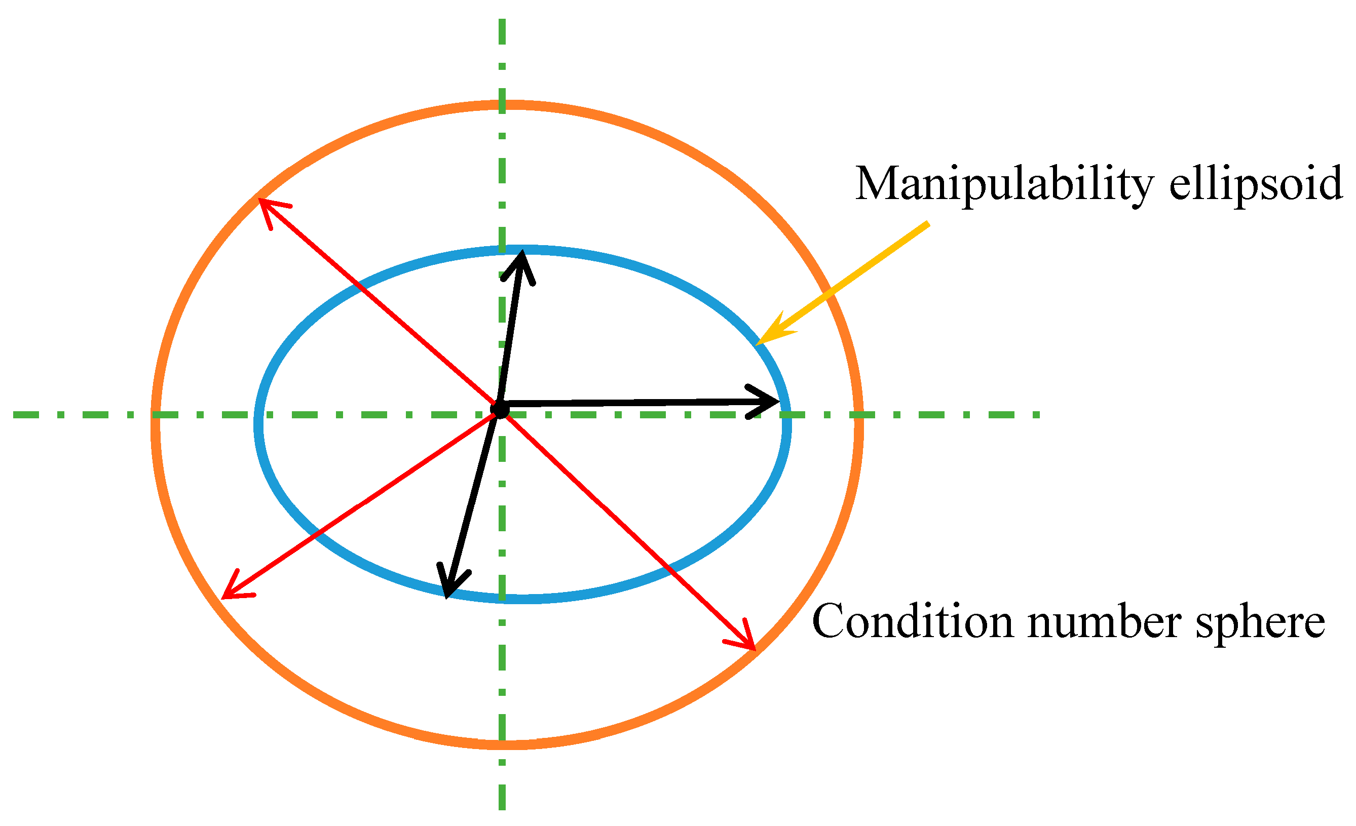
4.1. Justification of Using Condition Number

The evaluation of the configuration of the CKC system that executes the motion can be based on well-known dexterity indices [25] such as the manipulability index, the condition number, the minimum singular value (MSV), and MVR. The manipulability index presents the ability of the system for performing the high TCP velocity motion with low overall joint velocity. In the previous paper [26], the evaluation of the CKC system configuration was based on the manipulability index. The MSV presents the minimum kinematic ability of the system, whereas the MVR index shows the kinematic ability of the system in certain directions. The condition number shows the kinematic isotropy of the manipulator and is considered as a measure of the accuracy of the system as well as avoiding the singularity [8,27,39,40,41]. The condition number is widely used with optimization procedures in robotics [24,30,31,32,33]. In this paper, the evaluation of the configuration of the CKC system is based on the condition number. The condition number of the Jacobian matrix is calculated as the ratio of the maximum singular value of the Jacobian matrix to the minimum singular value of the Jacobian matrix [25,28]. The condition number for the CKC is obtained by [25]:
C N ( θ _ h , θ _ r ) = σ m a x ( J C K C ) σ m i n ( J C K C )
The condition number is a better measure of the degree of ill-conditioning of the manipulator than the manipulability index [25]. When the Jacobian loses its full rank, the minimum singular value σ m i n is equal to zero; therefore, the condition number C N becomes infinity. In other words, the condition number is the measure of the kinematic isotropy of the Jacobian [41,42,43]. In [44], Asada and Granitio presented that isotropic configurations can be obtained by minimizing the condition number. The condition number does not have an upper bound, C N [ 1 , ] . Finally, the condition number is a good measure of the Jacobian matrix invertibility [45].

4.2. The Optimization of the Task Location

Determining the suboptimal task location is carried out by calculating the condition number during the motion of the hand along the path. The same procedures followed in our previous paper [26] were carried out in the current work. To define the motion, two velocities’ profiles are used in this work; the constant velocity profile and the minimum jerk velocity profile [46], which better approximates the human arm motion. As presented and discussed in detail in the previous paper [26]: both profiles produce similar results in the formulation of the task measure. Therefore, the constant velocity profile is used to obtain the best location of the task for reasons of simplicity. This velocity is given by:
v _ = [ c o s φ s i n φ 0 0 0 0 ] T c m / s
The joints’ velocities are obtained by solving Equation (2) as:
θ ˙ _ r θ ˙ _ h = J C K C I 6 I 6 v _
In Equation (5), the J C K C represents the pseudo-inverse of the Jacobian matrix of the CKC model. The joints’ angle vectors θ _ r k and θ _ h k are derived, respectively, as follows,
θ _ r k = θ ˙ _ r k T s + θ _ r k 1 θ _ h k = θ ˙ _ h k T s + θ _ h k 1
where T s is the fixed time-step.
The robot end-effector orientation remains constant through the entire motion. The initial joint angles θ _ r 0 and θ _ h 0 are derived by solving the inverse kinematic problem given the first endpoint coordinate x f , y f , z f and taking into account the joint limits θ _ r m i n , θ _ r m a x , θ _ h m i n , θ _ h m a x that were previously discussed in Section 3. Since the handle orientation is fixed and it is known that both the human arm and the manipulator are not redundant, the inverse kinematic solution is therefore analytically obtained. Both the Cartesian and the configuration space are discretized and the condition number of the CKC is calculated using Equation (3) for every iteration “ k ” during the motion along the fixed-length line segment.
The main objective is finding the coordinates of the first endpoint ( x f , y f , z f ) * of the straight-line segment and the φ * angle that maximizes the following objective function (in our case, the objective function is equal to the fitness function):
O b j = f i t n e s s f u n c t i o n = f u n x f , y f , z f , φ = min k = 1 n C N θ _ h k , θ _ r k
In Equation (7), the condition number C N θ _ h k , θ _ r k is obtained using Equation (3), while its minimum value along the path is based only on the straight-line segment location, which is defined by x f , y f , z f , φ .
The GA is utilized to find the best task location. The GA has many advantages [24,47,48,49], as follows. The GA can work with discrete or discontinuous functions. The objective function in the GA can be numerical or logical because the variables are coded. This provides the GA with great application flexibility for a wide range of systems. The GA evaluates a population of possible solutions instead of a single point. Therefore, it can avoid being trapped in local optimal solutions. The GA deals with the objective function itself when exploring the search space and has no need for derivative computation/secondary functions. Finally, the GA is applicable in the optimization of many systems because of no restrictions for the objective function definition. The GA has both operation simplicity as well as the precision of the results.
The best task location given by the GA is:
( x f , y f , z f , φ ) * = argmax x f , y f , z f , φ f u n x f , y f , z f , φ
As presented in the previous paper [26], in the GA terminology, the first endpoint coordinates of the task x f , y f , z f and the angle φ are defined as genes, whereas the whole set composes a chromosome. A visual explanation for that process is shown in Figure 2. For these optimization parameters, real-time encoding is used. Their constraints in the workspace are chosen for the motion along the straight-line segment to be feasible for both the human and the robot. The optimization parameters’ constraints with respect to the inertial frame are:
x f 0.5 , 0.3 m , y f 0.15 , 0.2 m , z f 0.1 , 0.4 m , φ p i , p i r a d .
These constraints are found experimentally by moving the robot end-effector and the human arm model to their limits and selecting a subset of the cross-section of their workspaces. An overview of the proposed genetic algorithm used in the presented work with its inputs and outputs is illustrated as shown in Figure 3.
The one-point crossover and adapt feasible mutation operations are presented in Figure 4. The operations are applied upon chromosomes. During the crossover, two different chromosomes exchange some of their genes, resulting in creating two new chromosomes in the next generation. In the mutation, one or more genes of a chromosome are changed randomly, resulting in a new chromosome in the next generation.
The GA terminates when the number of generations exceeds the generation limit (No. of generations > the generation limit) or when the specific number of consecutive generations finds the same chromosome as the best-fit chromosome, which is referred as a stall generation limit. In this work, the selected generation limit is equal to 200, the stall generation limit is equal to 15, and the population size is equal to 35. The probabilities of mutation and one-point crossover operation are 0.2 and 0.8, respectively.
The pseudo-code summarizing the proposed procedure for determining the best location of the task is the same, which is presented in [26], but in the current work, the manipulability index is changed by the condition number index.

The Results from the Optimization Procedure

The resulting results from the proposed procedure to determine the suboptimal location of the considered path based on the condition number are presented in Figure 5, Figure 6 and Figure 7.
As shown in Figure 5, the manipulator with the blue color represents the human arm and the manipulator with the orange color represents the KUKA LWR robot. The axis of the handle movement along the determined best task location is marked in red. The motion starts from these configurations, which are presented in Figure 5, and in the direction of the positive x axis (with respect to the coordinate system attached to the robot end-effector), and the robot handle travels for 32 c m .
In Figure 6, the determined path (marked in red) as well as the first and the second endpoints are presented. The first point of the task is located at 0.4999 m , 0.1637 m , 0.3453 m with respect to the inertial frame and the angle φ of the path direction is equal to 77.5 d e g . We should point out that these results obtained from the proposed procedure are close to the directional preference obtained from ergonomics and in the introduced approach, the proposed task-based condition number measure represents the dexterity of the CKC formulated by the human arm grasping the manipulator handle. As shown from Figure 5 and Figure 6, the obtained configuration of both the human arm and the manipulator in the current work (based on the condition number) is different from the configuration obtained in the previous paper [26], which was based on the manipulability index. This is normal since the equation used for calculating the condition number is different from the one used for calculating the manipulability index. The condition number is calculated from (3), whereas the manipulability index is calculated using J C K C J C K C T . In addition, the motion in the current work starts from the obtained configurations in the direction of the positive x axis, whereas in the previous work, the motion started from the obtained configurations in the direction of the negative x axis.
The variation of the condition number index along the path in the determined suboptimal location is shown in Figure 7. The maximum value of the condition number occurs at the beginning (signified by a small red circle) and is equal to 15.22. The minimum value of the condition number is given after 13.5 s after the beginning of the motion and is equal to 8.907. In contrast, in our previous work [26], the minimum value of the manipulability index occurred at the beginning, whereas the maximum value of the manipulability index occurred after 23 s after the beginning of the motion.
An arbitrarily chosen task location is presented in Figure 8 with its condition number in Figure 9 to be compared with the results obtained by the proposed procedure (presented in Figure 6 and Figure 7). This arbitrary task location is chosen after many trials with the GA until the best case is found. Although the condition number in the case of the arbitrarily chosen task (Figure 9) is lower during the motion than the corresponding one obtained by the proposed procedure (Figure 7), the comfort of the human hand in the case of the arbitrarily chosen task is the worst, and we found that joint 5 of the human hand model is out of the marginal comfort range [35].
At the end of this section, we summarize that a high performance of the task location for both the human arm and the manipulator is achieved, in which the minimum value of the condition number of the CKC is maximized, taking into consideration the constraints of both the robot and human arm using a GA. The characteristics of the motion along this path and along the other two paths are investigated and evaluated experimentally in the next section.

5. Experimental Evaluation of the Proposed Approach—Step 3

This section presents the experimental set-up and the performed experiments. The experimental results are evaluated by using the proposed evaluation criteria and the questionnaire, which are related to ergonomics. The movement along the straight-line segment in the determined suboptimal location is compared with the movement along the other two randomly selected directions of the straight-line segments with the help of 15 subjects.

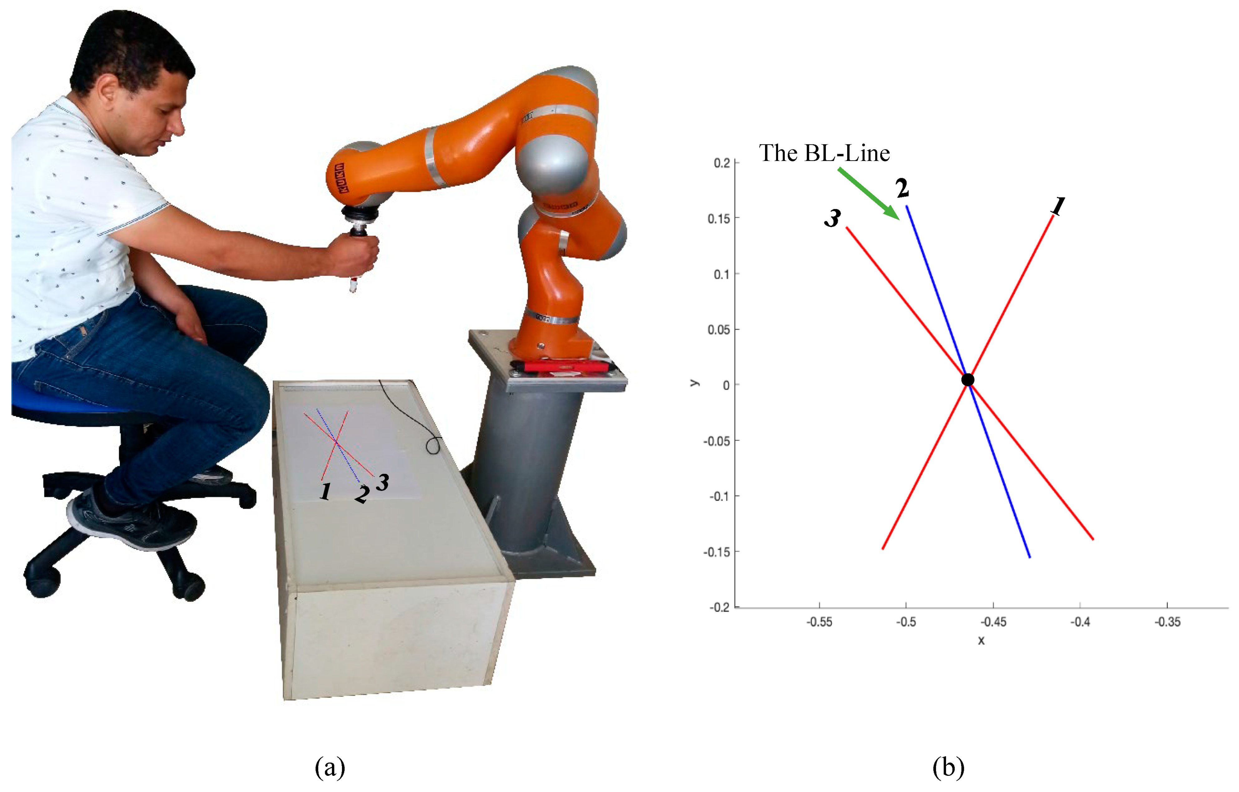
5.1. The Experimental Set-Up

KUKA LWR robot is used for the experimental part. The KUKA LWR collaborative robot [50,51] has an extremely light anthropomorphic structure, using 7 revolute joints. In addition, it is driven using compact brushless motors through harmonic drives. The presence of such transmission elements introduces a dynamically time-varying elastic displacement at each joint, between the angular position of the motor and that of the driven link. All joints of the robot have position sensors on the motor and link sides as well as a joint torque sensor. The KR C5.6 lr robot controller unit with the fast research interface (FRI) can provide, at a 1 millisecond sampling rate: (1) the link position; (2) the velocity and (3) measurements of the joint torque; and (4) the estimation of the external torques [52]. The KUKA LWR robot, which is equipped with an external force/torque sensor mounted at its end-effector, is presented in Figure 10.
As shown in Figure 10, the blue line (line 2) presents the direction where the human operator guides the robot handle with the task-based condition number index given by the proposed method as the best location-line (BL-line). During the experiment, the human operator is asked for moving the robot handle along this line (BL-line) and along other two random straight lines (line 1 and line 3, red color in Figure 10). The coordinates of the endpoints of the considered three straight-line segments are presented in Table 2. A laser pointer is attached to the handle to project the robot position to the table, where the initial point (the midpoint of the lines) as well as the targets’ points (the endpoints of the lines) are marked visually for assisting the human operator with visual feedback. For ease, the human operator is asked to begin the task from the centers of the lines (black point in Figure 10b) and travel back and forth to the endpoints of the line and then stop at the center point.
The human operator moves the robot end-effector via an admittance controller. It is suggested that the dynamics of the motion along the x and y axes are uncoupled. The admittance controller equation is given by [53,54,55]
F x F y = m x 0 0 m y V ˙ a x V ˙ a y + c x 0 0 c y V a x V a y
where the velocities V a x and V a y are the outputs of the admittance controller in x and y directions, respectively. m x and m y are the virtual inertia coefficients in x and y directions, respectively. c x and c y are the virtual damping coefficients in x and y directions, respectively. F x and F y are the applied forces by the operator in x and y directions, respectively, and they are the inputs to the admittance controller.
In the current work, the constant admittance controller (constant parameters; virtual damping and inertia) is chosen for simplicity. The virtual damping and the virtual inertia are selected as in our previous paper [26]. The virtual damping is equal to c x = c y = 10.0 N s / m , whereas the virtual inertia is equal to m x = m y = 3.0 k g . These values achieve the stability of the system during the experiment [26,53]. The singularity during the experiments is avoided and this is normal since the condition number is used to show the kinematic isotropy of the manipulator; and one advantage from the isotropic configuration is avoiding singularity [8]. As discussed in detail in the previous paper [26], the proposed procedure for the best location determination, where a constant velocity is used, does not contradict with the experimental work, where the velocity of the robot handle depends on the human hand motion. According to [46], the velocity profile of the free motion of the human hand follows the minimum jerk trajectory profile, but the error between this velocity and the actual velocity of the robot handle guided by the subject is high since the constant admittance controller is used (see Figure 11 and Appendix B).

5.2. The Experimental Results

The performance of the movement along line 2 (the BL-line) is compared with the movement along the two randomly directed straight-line segments (lines 2 and 3). The movement is carried out by fifteen (15) subjects aged 21 to 48 years old, thirteen of whom are male, two females, and all are right-handed. Each subject is asked to sit in the specific position and then grasp the robot handle from the initial position (the midpoint of the line), guide it to the target position (one endpoint of the line), then back to the initial position, continue to the other endpoint of the line, and complete the motion by guiding it once again back to the initial position. Before executing the experiments, the subject is asked to perform the movement as a trial to be familiar with the robot handle movement.

5.2.1. The Evaluation Criteria

The performance of each subject is measured using criteria adapted from ergonomics studies for comparative reasons. The task completion time, the achieved accuracy, the trajectory smoothness, and the force smoothness, as well as the interaction force are the five criteria proposed in [56]. In the current work, the performance is evaluated based the following criteria, which were also used in the previous work [26]:
(1)
The position error (distance discrepancy): It is defined as the absolute value of the difference between the straight-line segment and the actual position of the robot end-effector. The average/mean of the position error obtained by each subject is calculated, and then the mean value for the 15 subjects is calculated. Indeed, the position error expresses the achieved accuracy. In [56], the arc-length was used as the accuracy measure, and the smoothness by measuring the number of peaks in the trajectory was used for evaluating the precision in task execution.
(2)
The applied effort by the human operator to the robot handle during the movement: The effort is calculated as the integration of the applied forces over the travelled distance. The human effort in the x direction by each subject is calculated as E x = F x d x , whereas the effort in the y direction by the subject is E y = F y d y . Afterward, the total effort by each subject is calculated as E = E x 2 + E y 2 . Finally, the mean value from the required efforts by the 15 subjects is obtained. In [56], the interaction force is used to show how much effort the user needed for task completion.
(3)
The task completion time required for completing the above specific movement: The task completion time for every subject is obtained, then the mean value for the 15 subjects is calculated and is the same criterion to the one used in [56].
(4)
The oscillations during the movement: The 1D Fourier Transform of the applied force by the subject is calculated while considering frequencies less than 100 Hz. The mean value of the frequencies for each subject is calculated, and then the mean value for the 15 subjects is obtained. This criterion shows the quality of the motion, and it is similar to the force smoothness as well as the trajectory smoothness criteria measured in [56].

5.2.2. The Results from Measurements

The obtained results by the subjects from the executed experiments are presented in Figure 11 and Figure 12, and in Table 3.
Figure 11 presents the actual velocity of the robot handle obtained by only two out of the overall fifteen subjects. As shown in the figure, the robot handle velocity is higher along line 3 and line 2 (the BL-line) compared with the velocity along line 1. The smoothness of the movement along line 2 (BL-line) is better compared with the other two random lines. In addition, the oscillations during the movement along the BL-line are lower. This leads us to determine that the achieved accuracy along the BL-line is the best. However, this figure shows only the results from two subjects, so the results from all 15 subjects should be compared for a better description, as in Table 3. The actual velocity of the robot end-effector, shown in Figure 11, follows the pattern of the minimum jerk trajectory profile as presented in detail in Appendix B.
In Figure 12, the actual position of the robot end-effector and the considered three straight-line segments are presented/drawn. As shown from the figure, the position error during the movement along line 3 and the BL-line (line 2) is lower (better) than the one along line 1, which represents the worst case. Although the position error along line 3 is low, the error at its target points (endpoints) is high. Indeed, the position error is expected to be lower (the accuracy is higher) in the case of the BL-line, since the condition number is considered as a measure of the accuracy of the system.
As presented in Table 3, the obtained results from the 15 subjects during the movement along line 1, line 2 (BL-line), and line 3 are compared. The required human effort for the movements along line 1 is lower compared with the required human effort for the movements along the BL-line and line 3. Approximately, the human required effort during the movement along the BL-line is the same with line 3.
In the case of the position error, the position error obtained along the BL-line (line 2) is the lowest compared with line 1 and line 3. This means that the achieved accuracy obtained along line 2 is the best (highest). The position error obtained along line 1 is the highest, which means that the accuracy along line 1 is the worst.
The required time for completing the movement along line 3 is shorter compared with the time required for line 2 and line 3. This means that the velocity along line 3 is the highest. The required time for completing the movement along line 1 is the longest, which means that this movement is the slowest one.
The oscillations of the robot end-effector during the movement are also compared. The average number of frequencies was lower along line 2 compared with lines 1 and 3. This means that the stability of the robot and the accuracy achieved during the movement along line 2 are the best. The average number of frequencies was the highest along line 1.
From the above discussion, we deduce that the line drawing in different directions has an opposite effect in terms of the speed and the accuracy. This occurs when the subjects’ task performance between lines 2 (BL-line) and 3 are compared. Specifically, line drawing in the movement direction of line 2 (BL-line) favors a smooth pace of movement, which results in a better task performance in terms of accuracy and stability, but at the expense of lower speed and longer completion time. Instead, drawing along the direction of line 3 favors a rather rough movement of the robot end-effector (as it is indicated by the average number of oscillations), which is considered time-saving, but with low accuracy and stability. It should be noted that none of the above pros and cons are clear in the movement along line 1. The reason is that task performance is characterized by very rough movements, which in turn increase both the number of corrections and the time required for task completion. Therefore, the results of the present study provide evidence in support of two movement directions based on the desired end; that is to say, line 2 (BL-line) results in a better performance of the robot end-effector in terms of accuracy and stability, whereas line 3 results in a better performance in terms of speed. This is expected since the condition number used with the proposed approach is considered as a measure of accuracy.

5.2.3. The Subjective Results

The questionnaire is given to each subject during the experiments to evaluate the proposed approach. Each subject is asked to rate the movement along the three straight-line segments, line 1, line 2 (BL-line), and line 3, in terms of the following three questions: (1) What type of effort is required to move the robot handle? (2) What is the level of oscillations during the experiment? (3) What is the human comfort level during the movement along each line? The subject answers each question by selecting one answer from the following: low, medium, or high. After all subjects finish the experiments, their answers are processed/evaluated. These subjective results are presented in Figure 13.
As presented in Figure 13, most subjects (93.33%) expressed that their required effort to move the robot handle along the BL-line (line 2) was low. Also, the subjects (60% of them) responded that their required effort was low during the movement along line 1. In the case of movement along line 3, the subjects (60% of them) recorded medium effort.
In the case of the oscillations during movement, the oscillations felt by the subjects during the movement along line 2 (the BL-line) were low (53.33% of the subjects), whereas the oscillations along lines 1 and 3 were medium (46.67% of the subjects).
The best (highest) human comfort level was recorded during the movement along line 2 (86.67% of the subjects). This highest comfort level comes from the fact that the subject’s hand felt more comfortable during his guidance of the robot end-effector to move in this configuration (line 2), and that it was easier to move his hand in this direction with high accuracy.
From these results, we conclude that the performance during the movement along line 2 (the BL-line) is very good and achieves the lowest oscillation with high comfortability. These subjective results support/advocate the results from the measurements, which are presented in Table 3. Moreover, these results prove the success and the effectiveness of the proposed approach.
A video presenting some of the experiments is attached in the Supplementary Materials of this paper.

5.3. Discussions of the Results

As shown from the obtained results, the proposed approach, which is based on the condition number index, contributes in improving the HRI in terms of the achieved accuracy and the stability as well as the human comfort, but at the expense of the task speed. Accuracy is a very important and crucial factor in HRI [57,58,59], particularly in some robotic applications such as surgical tasks, assembly tasks, transferring objects, and welding processes. The results from the current approach are compared with the previous approach [26] based on the manipulability index in Table 4.
As shown in Table 4, the resulting position error obtained during the movement along the BL-line based on the condition number index is higher compared with the BL-line based on the manipulability index. In addition, the task completion time is lower in the case of the BL-line based on the condition number index. This means that the robot end-effector velocity along the BL-line based on the condition number is higher. Indeed, we were expecting that the robot end-effector velocity along the BL-line based on the manipulability index would be higher; however, our results prove the contrary. This because of the following: when the condition number is closer to unity, the manipulability ellipsoid almost becomes a sphere [60]. In the case of the sphere, the robot end-effector can move in all directions uniformly (see the red arrows in Figure 14), whereas in the case of the ellipsoid, the robot end-effector movement is different in all directions (see black arrows in Figure 14). In the direction of the major axis of the ellipsoid, the robot end-effector can move at high speed, whereas in the direction of the minor axis of the ellipsoid, the robot end-effector can move at low speed. In our current case, when the minimal of the condition number is maximized, the obtained sphere is larger (see Figure 14, orange sphere) compared with the obtained manipulability ellipsoid (see Figure 14, blue ellipsoid) when the minimal of the manipulability index is maximized in [26]. Therefore, this is why the robot end-effector velocity in our results is higher (the position error is higher, and the task completion time is lower) along the BL-line based on the condition number index compared with the one along the BL-line based on the manipulability index.
Another reason that can also be considered is that, in the case of the manipulability index-based approach, the human hand as the subject is different from the actual subjects’ hands in the case of the condition number-based approach.
As is also presented in Table 4, the oscillations (average number of frequencies) in the case of the BL-line based on the manipulability index (52.51 Hz) are higher compared with the current approach (BL-line based on the condition number (29.01 Hz)), which means that the movement of the robot end-effector along the BL-line based on the manipulability index is less stable than the one along the BL-line based on the condition number.
Depending on the comparison, between the BL-line and the two other randomly directed line directions presented in the current work and in [26], we can say that that the results obtained from our previous approach [26], which was based on the manipulability index, prove that the previous approach contributes to improving the HRI in terms of task speed as well as human comfort, but at the expense of the achieved accuracy. On the contrary, the current condition number-based approach improves the HRI in terms of the achieved accuracy as well as human comfort. We can conclude that both our approaches yield to the finding, which reflects a speed–accuracy trade-off, predicting that faster movements are executed with lower accuracy, and vice versa [18,19].
Both our current results and the previous results [26] are in line with the works related to ergonomics, which are presented in [56,61] for improving the HRI. In [61], the robot used the dynamic model of the whole-body of the human for optimizing the position of the co-manipulation task within the workspace constrained by the human arm manipulability. This approach thus leads to reducing the work-related strain and increasing the productivity of the human co-worker. In a similar way, our proposed approaches (based on condition number/manipulability indexes) increased human comfort levels. In addition, in [56], a manipulability-based online manipulator stiffness adaptation was presented; the results from this approach proved that the task completion time was low, and the force profile was smooth, as is presented in our work.

6. Conclusions and Future Work

This manuscript proposes an approach to improve the performance in human–robot co-manipulation. The system of the human arm grasping the robot handle is modeled as a closed kinematic chain (CKC). Then, a task-based measure is formulated for this CKC by determining the minimum value of the CKC condition number along the path. This task-based measure is maximized to determine the suboptimal path location.
KUKA LWR robot is used for the experiments and the movement along the BL-straight-line segment and is compared with the other two straight-line segments with random directions with the help of fifteen subjects.
The obtained results from the experiments prove that the human hand moves the robot end-effector along the BL-line with the highest achieved accuracy (the position error is the lowest) compared with the other two randomly directed line directions. Therefore, the velocity of the robot end-effector during the movement along the BL-line is low. The oscillations during the movement along the BL-line are the lowest compared with along the other two lines, which means that the stability of the robot end-effector along the BL-line is the best. Human comfort level records the highest score along the BL-line.
Comparing the results obtained by the current proposed approach with the results obtained from our previous approach [26], which was based on the manipulability index, we can summarize that the current proposed approach improves the HRI in terms of the achieved accuracy, stability, and human comfort level, but at the expense of the task speed and completion time. The previous approach [26] improved the HRI in terms of the task speed as well as the human comfort level, but at the cost of the achieved accuracy. Indeed, these results follow the finding which reflects a speed–accuracy trade-off, predicting that faster movements are executed with lower accuracy, and vice versa [18,19].
The promising results obtained by the current proposed approach and the previous approach [26] motivate us to further investigate the performance of human–robot co-manipulation by introducing performance measures based on other indices rather than manipulability and condition number.

Supplementary Materials

The following supporting information can be downloaded at: https://www.mdpi.com/article/10.3390/automation4030016/s1; A video is attached with the paper to show some experiments with the proposed approach.

Funding

The author declares that the manuscript did not receive any financial support.

Institutional Review Board Statement

All procedures performed in studies involving human participants were in accordance with the ethical standards of the institutional and/or national research committee and with the 1964 Helsinki declaration and its later amendments or comparable ethical standards.

Informed Consent Statement

Informed consent was obtained from all individual participants included in the study.

Data Availability Statement

The datasets (generated/analyzed) for this study are available from the corresponding author on reasonable request.

Conflicts of Interest

The author declares no conflict of interest.

Abbreviations

HRIHuman–robot interaction
HRCHuman–robot cooperation
LWRLightweight robot
DOFDegree of freedom
GAGenetic algorithms
DHDenavit–Hartenberg
C N Condition number
MSVMinimum singular value
O b j Objective function
CKCClosed kinematic chain
BL-lineBest location line

Appendix A. Kinematics of the Closed Kinematic Chain

When the human operator grasps the manipulator handle, a CKC is formulated. In this Appendix, the transformation matrices of the robot and the human arm and the Jacobian matrix of the closed kinematic chain (CKC) are presented.

Appendix A.1. The Transformation Matrices

In our case, the transformation matrices for the human arm and the KUKA robot are presented as follows:
(1)
The human arm:
T 1 0 h = cos θ h 1 0 sin θ h 1 0 sin θ h 1 0 cos θ h 1 0 0 1 0 0 0 0 0 1
T 2 1 h = cos θ h 2 0 sin θ h 2 0 sin θ h 2 0 cos θ h 2 0 0 1 0 0 0 0 0 1
T 3 2 h = cos θ h 3 0 sin θ h 3 0 sin θ h 3 0 cos θ h 3 0 0 1 0 0.4 0 0 0 1
T 4 3 h = cos θ h 4 sin θ h 4 0 ( 0.41 cos θ h 4 ) sin θ h 4 cos θ h 4 0 ( 0.41 sin θ h 4 ) 0 0 1 0 0 0 0 1
T 5 4 h = cos θ h 5 0 sin θ h 5 0 sin θ h 5 0 cos θ h 5 0 0 1 0 0 0 0 0 1
T 6 5 h = cos θ h 6 0 sin θ h 6 0 sin θ h 6 0 cos θ h 6 0 0 1 0 0 0 0 0 1
T 7 6 h = cos θ h 7 0 sin θ h 7 0 sin θ h 7 0 cos θ h 7 0 0 1 0 0.1 0 0 0 1
Therefore, T 2 0 h = T 1 0 h T 2 1 h , T 3 0 h = T 1 0 h T 2 1 h T 3 2 h , T 4 0 h = T 1 0 h T 2 1 h T 3 2 h T 4 3 h , T 5 0 h = T 1 0 h T 2 1 h T 3 2 h T 4 3 h T 5 4 h , T 6 0 h = T 1 0 h T 2 1 h T 3 2 h T 4 3 h T 5 4 h T 6 5 h , T 7 0 h = T 1 0 h T 2 1 h T 3 2 h T 4 3 h T 5 4 h T 6 5 h T 7 6 h .
(2)
The KUKA robot:
T 1 0 r = cos θ r 1 0 sin θ r 1 0 sin θ r 1 0 cos θ r 1 0 0 1 0 0.3105 0 0 0 1
T 2 1 r = cos θ r 2 0 sin θ r 2 0 sin θ r 2 0 cos θ r 2 0 0 1 0 0 0 0 0 1
T 3 2 r = cos θ r 3 0 sin θ r 3 0 sin θ r 3 0 cos θ r 3 0 0 1 0 0.4 0 0 0 1
T 4 3 r = cos θ r 4 0 sin θ r 4 0 sin θ r 4 0 cos θ r 4 0 0 1 0 0 0 0 0 1
T 5 4 r = cos θ r 5 0 sin θ r 5 0 sin θ r 5 0 cos θ r 5 0 0 1 0 0.39 0 0 0 1
T 6 5 r = cos θ r 6 0 sin θ r 6 0 sin θ r 6 0 cos θ r 6 0 0 1 0 0 0 0 0 1
T 7 6 r = cos θ r 7 sin θ r 7 0 0 sin θ r 7 cos θ r 7 0 0 0 0 1 0.078 0 0 0 1
Therefore, T 2 0 r = T 1 0 r T 2 1 r , T 3 0 r = T 1 0 r T 2 1 r T 3 2 r , T 4 0 r = T 1 0 r T 2 1 r T 3 2 r T 4 3 r , T 5 0 r = T 1 0 r T 2 1 r T 3 2 r T 4 3 r T 5 4 r , T 6 0 r = T 1 0 r T 2 1 r T 3 2 r T 4 3 r T 5 4 r T 6 5 r , T 7 0 r = T 1 0 r T 2 1 r T 3 2 r T 4 3 r T 5 4 r T 6 5 r T 7 6 r .
As all the previous calculations are complex, MATLAB software was used to perform these computations.

Appendix A.2. The Jacobian Matrix

The common Cartesian velocity for the human arm and the manipulator is v _ = r ˙ _ , ω _ R 6 × 1 , which is obtained by [28]
v _ = J h θ ˙ _ h = J r θ ˙ _ r v _ v _ r = v _ h
where r and h represent the KUKA LWR model and the human arm, respectively. J r R 6 × 7 and J h R 6 × 7 are the Jacobian matrix for the KUKA LWR and for the human arm, respectively. θ ˙ _ r , θ ˙ _ h R 7 × 1 are the joints’ velocities for the KUKA LWR and for the human arm, respectively.
The Jacobian matrix J (either J h or J r ) is determined as
J = J 1 J 2 J 3 J 4 J 5 J 6 J 7
J i , where i is the column of the Jacobian, is determined by,
J i = k _ i 0 × p _ 7 0 p _ i 0 k _ i 0
The vector k _ R 3 × 1 represents the rotation about the z axis, and p _ R 3 × 1 represents the translation vector obtained from the transformation matrix:
T i 0 = i _ i 0 J _ i 0 k _ i 0 p _ i 0 0 0 0 1
Therefore, it is easy then to calculate the Jacobian matrices J h and J r from Equations (A2) and (A3).
The Jacobian matrix of the CKC model J C K C R 12 × 14 is written by the following equation by combining the two Jacobians [38]:
J r 0 0 J h θ ˙ _ r θ ˙ _ h = J C K C θ ˙ _ r θ ˙ _ h = I 6 I 6 v _
As all the previous calculations are complex, MATLAB software was used to perform these computations.

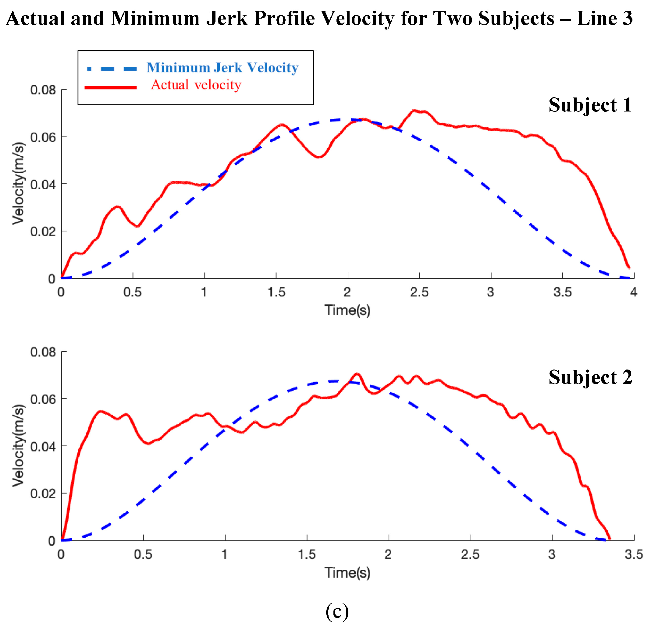
Appendix B. The Comparison between the Actual Velocity of the Robot End-Effector and the Velocity of the Minimum Jerk Trajectory Profile

As we stated previously in Section 5, Figure 11 presents the actual velocity of the robot end-effector V = V x 2 + V y 2 obtained from two subjects only, out of fifteen subjects, during the movement along lines 1, 2 (BL-line), and 3. This movement tends to approximate the minimum jerk trajectory profile. To prove this concept, the actual velocity of the robot end-effector shown in Figure 11 is compared with the reference velocity of the minimum jerk trajectory. For this comparison, e.g., the first loop of the movement (starting from the initial position to the first endpoint of the line) along each line (1, 2, 3), from Figure 11, is used for a comparison with the minimum jerk trajectory velocity profile. This comparison between both velocities’ profiles is presented in Figure A1.
Figure A1. The comparison between the actual velocity of the robot end-effector and the velocity of the minimum jerk trajectory profile during the movement along (a) line 1, (b) line 2 (BL-line), and (c) line 3. The blue dashed curve in the diagrams represents the velocity of the minimum jerk trajectory profile. The red curve represents the actual velocity of the robot end-effector. In every figure (a), (b), or (c)), the diagram at the top is for one subject, whereas the diagram at the bottom is for the other subject.
Automation 04 00016 g0a1aAutomation 04 00016 g0a1b
As shown in Figure A1, even if the tendency of the robot’s actual velocity is to follow the minimum jerk trajectory profile, high error appears between both of the two velocities compared to the results obtained from the variable admittance controller (VAC) presented in [53,54]. The constant admittance controller is chosen in our work for simplicity, and it is the reason for such a discrepancy, which does not affect the calculation of the proposed measure. From Figure A1, it is also clear that the approximation between both two velocities is better along line 2 (BL-line) compared with the other two straight-line segments. In addition, the results obtained along line 2 are smoother and with less oscillations. This means that the achieved accuracy along line 2 (BL-line) is the best. From the figure, the worst case occurs with line 1.

References

  1. Sharkawy, A.-N.; Koustoumpardis, P.N. Human–Robot Interaction: A Review and Analysis on Variable Admittance Control, Safety, and Perspectives. Machines 2022, 10, 591. [Google Scholar] [CrossRef]
  2. Sharkawy, A.-N. Intelligent Control and Impedance Adjustment for Efficient Human-Robot Cooperation. Ph.D. Thesis, University of Patras, Patras, Greece, 2020. [Google Scholar] [CrossRef]
  3. Wang, B.; Hu, S.J.; Sun, L.; Freiheit, T. Intelligent welding system technologies: State-of-the-art review and perspectives. J. Manuf. Syst. 2020, 56, 373–391. [Google Scholar] [CrossRef]
  4. Hord, S.M. Working Together: Cooperation or Collaboration; The University of Texas at Austin: Austin, TX, USA, 1981. Available online: https://files.eric.ed.gov/fulltext/ED226450.pdf (accessed on 25 February 2022).
  5. Vianello, L.; Gomes, W.; Maurice, P.; Aubry, A.; Ivaldi, S. Cooperation or collaboration? On a human-inspired impedance strategy in a human-robot co-manipulation task. HAL Open Sci. 2022. Available online: https://hal.science/hal-03589692 (accessed on 25 February 2022).
  6. Inkulu, A.K.; Bahubalendruni, M.V.A.R.; Dara, A.; SankaranarayanaSamy, K. Challenges and opportunities in human robot collaboration context of Industry 4.0—A state of the art review. Ind. Rob. 2022, 49, 226–239. [Google Scholar] [CrossRef]
  7. Michalos, G.; Karagiannis, P.; Makris, S.; Tokçalar, Ö.; Chryssolouris, G. Augmented Reality (AR) Applications for Supporting Human-robot Interactive Cooperation. Procedia CIRP 2016, 41, 370–375. [Google Scholar] [CrossRef]
  8. Klein, C.A.; Miklos, T.A. Spatial Robotic Isotropy. Int. J. Rob. Res. 1991, 10, 426–437. [Google Scholar] [CrossRef]
  9. Meulenbroek, R.G.J.; Thomassen, A.J.W.M. Stroke-direction preferences in drawing and handwriting. Hum. Mov. Sci. 1991, 10, 247–270. [Google Scholar] [CrossRef]
  10. Meulenbroek, R.G.J.; Thomassen, A.J.W.M. Effects of handedness and arm position on stroke-direction preferences in drawing. Psychol. Res. 1992, 54, 194–201. [Google Scholar] [CrossRef]
  11. Dounskaia, N.; Wang, W. A preferred pattern of joint coordination during arm movements with redundant degrees of freedom. J. Neurophysiol. 2014, 112, 1040–1053. [Google Scholar] [CrossRef] [PubMed]
  12. Dounskaia, N.; Goble, J.A. The role of vision, speed, and attention in overcoming directional biases during arm movements. Exp. Brain Res. 2011, 209, 299–309. [Google Scholar] [CrossRef] [PubMed]
  13. Goble, J.A.; Zhang, Y.; Shimansky, Y.; Sharma, S.; Dounskaia, N.V. Directional Biases Reveal Utilization of Arm’s Biomechanical Properties for Optimization of Motor Behavior. J. Neurophysiol. 2007, 98, 1240–1252. [Google Scholar] [CrossRef]
  14. Dounskaia, N.; Shimansky, Y. Strategy of arm movement control is determined by minimization of neural effort for joint coordination. Exp. Brain Res. 2016, 234, 1335–1350. [Google Scholar] [CrossRef]
  15. Schmidtke, H.; Stier, F. Der Aufbau Komplexer Bewegungsablaufe Aus Elementarbewegungen [The Development of Complex Movement Patterns from Simple Motions]; Forschungsbericht des Landes Nordrhein-Westfalen; Springer-Verlag: Berlin/Heidelberg, Germany, 1960; Volume 822, pp. 13–32. [Google Scholar]
  16. Sanders, M.; McCormick, E. Human Factors in Engineering and Design, 7th ed.; McGraw Hill: New York, NY, USA, 1993. [Google Scholar]
  17. Levin, O.; Ouamer, M.; Steyvers, M.; Swinnen, S.P. Directional tuning effects during cyclical two-joint arm movements in the horizontal plane. Exp. Brain Res. 2001, 141, 471–484. [Google Scholar] [CrossRef]
  18. Seow, S.C. Information Theoretic Models of HCI: A Comparison of the Hick-Hyman Law and Fitts’ Law. Hum.–Comput. Interact. 2005, 20, 315–352. [Google Scholar] [CrossRef]
  19. Hancock, P.A.; Newell, K.M. The movement speed-accuracy relationship in space-time. In Motor Behavior; Heuer, H., Kleinbeck, U., Schmidt, K., Eds.; Springer: Berlin/Heidelberg, Germany, 1985; pp. 153–188. [Google Scholar] [CrossRef]
  20. Berret, B.; Jean, F. Why Don’t We Move Slower? The Value of Time in the Neural Control of Action. J. Neurosci. 2016, 36, 1056–1070. [Google Scholar] [CrossRef]
  21. Rigoux, L.; Guigon, E. A Model of Reward- and Effort-Based Optimal Decision Making and Motor Control. PLoS Comput. Biol. 2012, 8, e1002716. [Google Scholar] [CrossRef]
  22. Shadmehr, R.; Orban de Xivry, J.J.; Xu-Wilson, M.; Shih, T.-Y. Temporal Discounting of Reward and the Cost of Time in Motor Control. J. Neurosci. 2010, 30, 10507–10516. [Google Scholar] [CrossRef]
  23. Wang, C.; Xiao, Y.; Burdet, E.; Gordon, J.; Schweighofer, N. The duration of reaching movement is longer than predicted by minimum variance. J. Neurophysiol. 2016, 116, 2342–2345. [Google Scholar] [CrossRef]
  24. Khatami, S. Kinematic Isotropy and Robot Design Optimization Using a Genetic Algorithm Method. Ph.D. Thesis, The University of British Columbia, Vancouver, BC, Canada, 2001. [Google Scholar]
  25. Patel, S.; Sobh, T. Manipulator Performance Measures—A Comprehensive Literature Survey. J. Intell. Robot. Syst. Theory Appl. 2014, 77, 547–570. [Google Scholar] [CrossRef]
  26. Sharkawy, A.; Papakonstantinou, C.; Papapostopoulos, V.; Moulianitis, V.C.; Aspragathos, N. Task Location for High Performance Human-Robot Collaboration. J. Intell. Robot. Syst. 2019, 100, 183–202. [Google Scholar] [CrossRef]
  27. Merlet, J.-P. Jacobian, manipulability, condition number and accuracy of parallelrobots. J. Mech. Des. 2005, 128, 199–206. [Google Scholar] [CrossRef]
  28. Murray, R.M.; Li, Z.; Sastry, S.S. A Mathematical Introduction to Robotic Manipulation; CRC Press: Boca Raton, FL, USA, 1994; ISBN 9780849379819. [Google Scholar]
  29. Nurahmi, L.; Caro, S. Dimensionally Homogeneous Jacobian and Condition Number. Appl. Mech. Mater. 2016, 836, 42–47. [Google Scholar] [CrossRef]
  30. Leger, J. Condition-Number Minimization for Functionally Redundant Serial Manipulators; McGill University: Montréal, QC, Canada, 2014. [Google Scholar]
  31. Stocco, L.; Salcudean, S.E.; Sassani, F. Fast Constrained Global Minimax Optimization of Robot Parameters. Robotica 2001, 16, 595–605. [Google Scholar] [CrossRef]
  32. Ayusawa, K.; Rioux, A.; Yoshida, E.; Venture, G.; Gautier, M. Generating persistently exciting trajectory based on condition number optimization. In Proceedings of the 2017 IEEE International Conference on Robotics and Automation (ICRA), Singapore, 29 May–3 June 2017; pp. 6518–6524. [Google Scholar]
  33. Swevers, J.; Ganseman, C.; Schutter, J.D.; Van Brussel, H. Experimental Robot Identification Using Optimised Periodic Trajectories. Mech. Syst. Signal Process. 1996, 10, 561–577. [Google Scholar] [CrossRef]
  34. Sharkawy, A.N. Sub-Optimal Configuration for Human and Robot in Co-Manipulation Tasks Based on Inverse Condition Number. In Proceedings of the 31st International Conference on Computer Theory and Applications, ICCTA 2021—Proceedings, Alexandria, Egypt, 11–13 December 2021; pp. 72–77. [Google Scholar]
  35. Kee, D.; Karwowski, W. The boundaries for joint angles of isocomfort for sitting and standing males based on perceived comfort of static joint postures. Ergonomics 2001, 44, 614–648. [Google Scholar] [CrossRef]
  36. Pheasant, S.; Haslegrave, C.M. Bodyspace: Anthropometry, Ergonomics and the Design of Work, 3rd ed.; CRC Press: London, UK, 2005. [Google Scholar]
  37. Kuka, L.W.R. User-Friendly, Sensitive and Flexible. Available online: https://www.kukakore.com/wp-content/uploads/2012/07/KUKA_LBR4plus_ENLISCH.pdf (accessed on 7 March 2020).
  38. Bicchi, A.; Prattichizzo, D. Manipulability of cooperating robots with unactuated joints and closed-chain mechanisms. IEEE Trans. Robot. Autom. 2000, 16, 336–345. [Google Scholar] [CrossRef]
  39. Ranjbaran, F.; Angeles, J.; Kecskemethy, A. On the Kinematic Conditioning of Robotic Manipulators. In Proceedings of the 1996 IEEE International Conference on Robotics and Automation, Minneapolis, MN, USA, 22–28 April 1996; pp. 3167–3172. [Google Scholar] [CrossRef]
  40. Gosselin, C.M. The optimum design of robotic manipulators using dexterity indices. Rob. Auton. Syst. 1992, 9, 213–226. [Google Scholar] [CrossRef]
  41. Kimt, J.; Khosla, P.K. Dexterity Measures for Design and Control of Manipulators. In Proceedings of the IEEE/RSJ International Workshop on Intelligent Robots and Systems IROS ’91, Osaka, Japan, 3–5 November 1991; pp. 758–763. [Google Scholar] [CrossRef]
  42. Chiu, S.L. Kinematic Characterization of Manipulators: An Approach To Defining Optimality. In Proceedings of the 1988 IEEE International Conference on Robotics and Automation, Philadelphia, PA, USA, 24–29 April 1988; pp. 828–833. [Google Scholar] [CrossRef]
  43. Angeles, J.; López-cajún, C.S. Kinematic Isotropy and the Conditioning Index of Serial Robotic Manipulators. Int. J. Rob. Res. 1992, 11, 560–571. [Google Scholar] [CrossRef]
  44. Asada, H.; Granito, J.A.C. Kinematic and Static Characterization of Wrist Joints and Their Optimal Design. In Proceedings of the 1985 IEEE International Conference on Robotics and Automation, St. Louis, MO, USA, 25–28 March 1985; pp. 244–250. [Google Scholar] [CrossRef]
  45. Gao, F.; Liu, X.; Gruver, W.A. The Global Conditioning Index in the Solution Space of Two Degree of Freedom Planar Parallel Manipulators. In Proceedings of the IEEE International Conference on Systems, Man and Cybernetics. Intelligent Systems for the 21st Century, Vancouver, BC, Canada, 22–25 October 1995; pp. 4055–4058. [Google Scholar] [CrossRef]
  46. Flash, T.; Hogan, N. The coordination of Arm Movements: An Experimentally Confirmed Mathematical Model. J. Neurosci. 1985, 5, 1688–1703. [Google Scholar] [CrossRef] [PubMed]
  47. Melanie, M. An Introduction to Genetic Algorithms, 1st ed.; MIT Press: Cambridge, MA, USA, 1999. [Google Scholar]
  48. Bodenhofer, U. Genetic Algorithms: Theory and Applications; Johannes Kepler University: Linz, Austria, 2003. [Google Scholar]
  49. Coley, D.A. An Introduction to Genetic Algorithms for Scientists and Engineers; World Scientific Publishing Co. Pte. Ltd.: Singapore, 1999. [Google Scholar]
  50. Sharkawy, A.-N.; Aspragathos, N. Human-Robot Collision Detection Based on Neural Networks. Int. J. Mech. Eng. Robot. Res. 2018, 7, 150–157. [Google Scholar] [CrossRef]
  51. Sharkawy, A.-N.; Ali, M.M. NARX Neural Network for Safe Human–Robot Collaboration Using Only Joint Position Sensor. Logistics 2022, 6, 75. [Google Scholar] [CrossRef]
  52. KUKA.FastResearchInterface 1.0, KUKA System Technology (KST), version 2; KUKA Roboter GmbH: Augsburg, Germany, 2011.
  53. Sharkawy, A.-N.; Koustoumpardis, P.N.; Aspragathos, N. Variable Admittance Control for Human-Robot Collaboration based on Online Neural Network Training. In Proceedings of the 2018 IEEE/RSJ International Conference on Intelligent Robots and Systems (IROS), Madrid, Spain, 1–5 October 2018; pp. 1334–1339. [Google Scholar]
  54. Sharkawy, A.-N.; Koustoumpardis, P.N.; Aspragathos, N. A Neural Network based Approach for Variable Admittance Control in Human- Robot Cooperation: Online Adjustment of the Virtual Inertia. Intell. Serv. Robot. 2020, 13, 495–519. [Google Scholar] [CrossRef]
  55. Sharkawy, A.-N. Minimum Jerk Trajectory Generation for Straight and Curved Movements: Mathematical Analysis. In Advances in Robotics and Automatic Control: Reviews; Yurish, S.Y., Ed.; International Frequency Sensor Association (IFSA) Publishing: Barcelona, Spain, 2021; Volume 2, pp. 187–201. Available online: https://www.sensorsportal.com/HTML/BOOKSTORE/Advances_in_Robotics_Reviews_Vol_2.pdf (accessed on 25 February 2022).
  56. Gopinathan, S.; Mohammadi, P.; Steil, J.J. Improved Human-Robot Interaction: A manipulability based approach. In Proceedings of the ICRA 2018 Workshop on Ergonomic Physical Human-Robot Collaboration, Brisbane, Australia, 21–25 May 2018. [Google Scholar]
  57. Erkaya, S. Effects of joint clearance on the motion accuracy of robotic manipulators. J. Mech. Eng. 2018, 64, 82–94. [Google Scholar] [CrossRef]
  58. Mavroidis, C.; Flanz, J.; Dubowsky, S.; Drouet, P.; Goitein, M. High performance medical robot requirements and accuracy analysis. Robot. Comput. Integr. Manuf. 1998, 14, 329–338. [Google Scholar] [CrossRef]
  59. Marônek, M.; Bárta, J.; Ertel, J. Inaccuracies of industrial robot positioning and methods of their correction. Teh. Vjesn.—Tech. Gaz. 2015, 22, 1207–1212. [Google Scholar] [CrossRef]
  60. Yoshikawa, T. Foundations of Robotics: Analysis and Control; MIT Press Cambridge: Cambridge, MA, USA, 1990; ISBN 0-262-24028-9. [Google Scholar]
  61. Peternel, L.; Kim, W.; Babic, J.; Ajoudani, A. Towards ergonomie control of human-robot co-manipulation and handover. In Proceedings of the 2017 IEEE-RAS 17th International Conference on Humanoid Robotics (Humanoids), Birmingham, UK, 15–17 November 2017; pp. 55–60. [Google Scholar] [CrossRef]
Figure 1. The human arm model in the fully extended case.
Automation 04 00016 g001
Figure 2. The proposed genetic algorithm (GA) terminology.
Automation 04 00016 g002
Figure 3. The inputs and outputs of the proposed genetic algorithm.
Automation 04 00016 g003
Figure 4. The crossover and mutation operations.
Automation 04 00016 g004
Figure 5. The suboptimal configuration of both the human arm and the manipulator as well as the direction of movement obtained by the proposed procedure.
Automation 04 00016 g005
Figure 6. The suboptimal path location.
Automation 04 00016 g006
Figure 7. The condition number index of the CKC formulated by the by the human arm grasping the manipulator handle along the determined suboptimal path location. The red spot is the maximum value, whereas the black spot is the minimum value.
Automation 04 00016 g007
Figure 8. The motion path in another task location.
Automation 04 00016 g008
Figure 9. The variation of the condition number of the CKC during the motion along the path shown in Figure 5. The red spot is the maximum value, whereas the black spot is the minimum value.
Automation 04 00016 g009
Figure 10. (a) The experimental set-up using the KUKA LWR robot and (b) the three straight-line segments proposed for the movement.
Automation 04 00016 g010
Figure 11. The actual velocity of the robot end-effector V = V x 2 + V y 2 by two subjects during the movement along the three straight-line segments. (a) The results from subject 1. (b) The results from subject 2.
Automation 04 00016 g011
Figure 12. The actual position of the robot handle and the considered straight-line segments (the blue color is the BL-line, whereas the red color is line 2 and line 3). (a) The results obtained by all 15 subjects. (b) The results obtained by only 3 subjects to show the position error more clearly.
Automation 04 00016 g012
Figure 13. The results obtained from the questionnaire by the 15 subjects for (a) the level of required effort, (b) the level of oscillations, and (c) the human comfort level during movement along the three straight-line segments.
Automation 04 00016 g013
Figure 14. The manipulability ellipsoid and condition number sphere when the minimal value of the manipulability/condition number index is maximized.
Automation 04 00016 g014
Table 1. The DH parameters of the human arm and the KUKA LWR robot.
JointHuman ArmKUKA Robot
θ h i d (m) a (m) α θ r i d (m) a (m) α
1 θ h 1 00 p i / 2 θ r 1 0.31050 p i / 2
2 θ h 1 00 p i / 2 θ r 1 00 p i / 2
3 θ h 1 0.40 p i / 2 θ r 1 0.40 p i / 2
4 θ h 1 00.41 0 θ r 1 00 p i / 2
5 θ h 1 00 p i / 2 θ r 1 0.390 p i / 2
6 θ h 1 00 p i / 2 θ r 1 00 p i / 2
7 θ h 1 0.10 p i / 2 θ r 1 0.0780 0
Table 2. The coordinates of the three lines’ segments, where the human operator moves the robot end-effector.
LineCenter Point
(Initial Point)
Coordinates
Angle   φ with the x Axis (deg)Line Segment Path Endpoints
The First EndpointThe Second Endpoint
xyzxyz
Line 1 x = 0.4622
y = 0.00024
z = 0.34371
71.9−0.41540.15280.3491−0.5139−0.14850.3410
Line 2
(BL)
−77.5−0.49990.16370.3453−0.4289−0.15610.3398
Line 3−63.2−0.53460.14190.3459−0.3924−0.13980.3391
Table 3. The mean values and standard deviations for the position error, the required human effort, the task completion time, and the oscillations during the movement along the three straight-line segments (lines 1, 2, and 3), considering the performance of the 15 subjects. The colored column represents the results along the BL-line.
Line Drawing Task PerformanceLine
Line 1 Line 2
(BL-Line)
Line 3
Position Error (cm)mean0.5210.4250.463
Std.0.1530.1870.195
Applied Effort (Nm)mean0.40730.5740.586
Std.0.190.2670.238
Task Completion
Time (s)
mean14.81012.61312.39
Std.4.834.914.76
Oscillations (Fourier Transform of the Applied Force) (Hz)mean of freq.37.5429.0133.633
Std.19.81419.02514.943
Table 4. The performance comparison during the movement along the BL-line is based on the manipulability index and along the BL-line based on the condition number index.
Line Drawing Task PerformanceLine
BL-Line Based on
Manipulability Index
BL-Line Based on
Condition Number
Position Error c m mean0.240.425
Std.0.200.187
Applied Effort ( N m ) mean0.5880.574
Std.0.3210.267
Task Completion
Time ( s )
mean16.9812.613
Std.5.564.91
Oscillations (Fourier Transform of the Applied Force) (Hz)mean of freq.52.5129.01
Std.20.6919.025
Disclaimer/Publisher’s Note: The statements, opinions and data contained in all publications are solely those of the individual author(s) and contributor(s) and not of MDPI and/or the editor(s). MDPI and/or the editor(s) disclaim responsibility for any injury to people or property resulting from any ideas, methods, instructions or products referred to in the content.

