
Virtual Commissioning of Linked Cells Using Digital Models in an Industrial Metaverse

Institute for Production and Informatics (IPI) Sonthofen, Mittagstrasse 28A, 87527 Sonthofen, Germany
*
Author to whom correspondence should be addressed.
Automation 2024, 5(1), 1-12; https://doi.org/10.3390/automation5010001
Submission received: 16 October 2023
/
Revised: 26 January 2024
/
Accepted: 29 January 2024
/
Published: 2 February 2024
(This article belongs to the Topic Smart Manufacturing and Industry 5.0)
Abstract
:Various software environments have been developed in the past to create digital twins of single cells or a digital twin of a factory. Each environment has its own strengths and weaknesses and has been designed with a specific focus. The environments that are able to holistically simulate complete factories are limited in terms of the modelling details required for the analysis of single manufacturing cells (e.g., manufacturer-independence of the individual digital twins) and their ability for virtual commissioning. This paper presents three options for realising a virtual commissioning of linked cells using a 3D integration platform with NVIDIA Omniverse, consisting of two different digital models fused into a combined model, also representing material flow. First, with a source/sink solution and unidirectional connector controlled by OPC UA; secondly, with a bidirectional connector, developed in the course of this elaboration, and an extension of the 3D integration platform controlled by Apache Kafka; thirdly, with a bidirectional connector and using only an extension of the 3D integration platform. The research demonstrates that virtually commissioning multiple linked digital twins from different manufacturers in a 3D platform with material flow makes a significant contribution to the industrial metaverse.
1. Introduction
With the current state-of-the-art, it is possible for companies to commission single machines and cells virtually. However, virtually commissioning the entirety of linked cells, such as the production line of an automobile manufacturer, is currently not possible. In order to be able to virtually commission interlinked cells in advance, even only considering material flow, high computing capacities are required, and the individual modular digital twins must be generated in a single simulation software for compatibility reasons. In general, Michael Grieves and John Vickers [1] describe a digital twin which represents real objects or subjects with their data, functions, and communication capabilities in the digital world. By inference, a digital twin is only a digital twin if a physical product exists and contains any information that can be determined by inspecting the real product. Grieves and Vickers also distinguishes between digital twin prototypes and digital twin instances which operate in digital twin environments [1]. According to the Grieves-Vickers definition, we therefore speak of digital models because we are partly dealing with conceptual digital simulations that do not have a direct physical counterpart. The focus of the paper is on the feasibility of the general architecture. In future projects, the methodologies will be validated with real machines (see Section 5).
Integrating different digital twins into a 3D integration platform offers numerous advantages for the production operator: the entire factory—from logistics and building management through to media supply—can be put into operation virtually. With the virtual commissioning of a complete factory, the factory process can be validated—both the material flow in the cell and any collisions between the individual cells or between the cells and the building. In addition, the overall control logic can be validated. Furthermore, virtual commissioning of the Manufacturing Execution System (MES) also becomes possible.
The following requirements can be formulated for a hybrid digital twin in a 3D integration platform. If a complete cell network consists of heterogeneous individual cells or machines whose digital twins were generated with different simulation software, a platform is needed into which different digital twins or different simulations can be integrated, independent of the manufacturer. On a 3D integration platform that is multi-user capable, the individual instances can interact with each other in “real time”, which continues to exist after the individual user has used it, unlike a common Web 2.0 application. If the above requirements are bundled together, depending on the definition, the required construct can be called an an “industrial metaverse” [2]. According to Zheng et al. [3], an industrial metaverse is not just the interaction of different heterogeneous 3D geometries. The digital twins of various systems, machines, halls and the entire environment are used via various services, such as a simulation engine, AI engine and other applications [3].
Innovative technologies, such as AI, IoT or industrial metaverse, which have a strong impact on industry and society, are often used as a guiding method for projects. In other words, solutions are defined in initial project steps to solve problems—a top-down methodology. In this work, a bottom-up methodology is chosen, meaning that a system “metaverse” is not used to solve a problem, but the problem is solved analytically from the bottom up. Expressed differently again, industry-related problems are identified and defined and then methodologies are developed that lead to a solution. The priority is not to create an industrial metaverse at the end, but to bring added values to the user.
A linked industrial cell is put into operation virtually with the help of a 3D integration platform. The individual modular digital twins are to be created using different software solutions. In addition, the material flow must be visible in the 3D integration platform. This means that different kinds of information about components (such as position, velocity, geometry, and other metadata) are to be conveyed from one cell to another. The individual digital twins are transformed into a uniform data format in order to be integrated into a 3D integration platform.
An additional requirement is that if something changes in the simulation software, for example when a robot moves, this change must be synchronised and transformed into the 3D integration platform. When something changes in the 3D integration platform, this information should be fed back into the virtual commissioning software. As different digital twins interact in the 3D integration platform and influence one another, the respective changes have to be transferred back to the respective authoring systems. This means that the synchronised data transformation from digital twin to 3D integration platform must be bidirectional. Further requirements for virtually commissioning factories include integrating digital twins from different manufacturers; also, creating data consistency between the authoring system and the 3D integration platform. In addition, it is necessary to transform the geometry data from every single authoring system into a uniform data format for the 3D integration platform. To handle this complexity, the concepts in this paper are defined in a modular way, meaning that the individual sub-methods of the entire system can be substituted and extended as desired.
The aim of this paper is to develop the requirements addressed in various methods. Generic examples are dealt with in these methods. This means that the individual cells under consideration are fictitious examples that have no real counterpart. In the conclusion, further projects are discussed in which the methodological results are tested using real machines and complete digital twins.
2. Related Works
Miriam Ugarte et al. [4] describe a concept in which the linking of different simulations for a virtual commissioning is realised by means of an OPC UA-intermediate level: On the one hand, controls are simulated in the concept and linked with digital representatives. On the other, an outlook is given on the endeavour to link entire cell networks. The paper shows that despite the necessity of being able to link different simulations, there is no software platform at the current state-of-the-art in which this linking takes place. Luyao Xia et al. [5] present a concept of an “ecosystem with digital twins in production”, consisting of three digital representatives: the factory, the product and the whole supply chain. To start with, the factory is integrated as a 2D model using Plant Simulation by Siemens. Later, the entire factory is loaded into Unity as a 3D model. The article shows that uniform data exchange and communication protocols are essential, but that the current state-of-the-art offers no commercial software solutions on the market that meet these requirements. In addition, the concept is not capable of linking virtually commissioned digital representatives from different manufacturers to form an entire production system. The need to standardise technologies and data interfaces is also identified by Anton Lidell et al. [6] in their summary of literature research addressing the topic of digital twins in the current state-of-the-art. Zheng et al. [3] says the industrial metaverse interaction concludes suppliers from different industrial assets like individual simulation software, which are far from mature world widely.
From the publications mentioned so far, it has become clear that it is necessary to be able to link different digital representatives and different simulations. Based on the publications and in our opinion, digital representatives should be able to stem from different manufacturers and thus from different simulation software.
Luis Omar Alpala et al. [7] describe the implementation of an industrial metaverse in the form of an entire factory. Several people can log into the virtual world simultaneously via virtual reality and walk through the virtual factory. Machines and cells are mapped in detail, but without behaviour. The authors conclude that the implementation of digital representatives will be an important addition to the industrial metaverse in the future. In comparison, Laurence C. Magalhaes et al. [8] describe the parallel operation of a digital/virtual representative and a real cell. In addition, the paper shows that linking and standardising different simulation software is essential for a functioning industrial metaverse. Xingqin Lin [9] elaborates a conceptual “network of digital twins” using NVIDIA Omniverse. The use case is a landscape environment with a road network as a training environment for autonomous driving, with the architecture consisting of modular digital/virtual representatives. The paper proposes focusing on the interaction between individual modular digital/virtual representatives in future research.
3. Methods
3.1. Virtual Commissioning
In general, commissioning is the “transfer of the system from the idle state to the permanent operation state” [10]. According to VDI/VDE 3693 [11], virtual commissioning is a “commissioning procedure which involves the testing of individual components and subfunctions of the automation system during development with the aid of simulation methods and models adapted to the task in question”. The result of the virtual commissioning is the validation of the complete system functionality without mechanical construction in the form of a “pre-commissioning” [12]. These configurations and methods differ in the type and scope of the representatives used, in the variations of the simulation tools and software, and in the communication method used between the simulation and representative and the real cell. In the following section, these differences are adapted to the different test configurations. Of the various software options for creating the digital twin used for virtual commissioning, Visual Components and CIROS are used in this paper. Visual Components software is used for applications including layout planning, production simulation, off-line programming and PLC verification [13], and CIROS simulation software (version: 7.2.0) for the virtual environment for PLC and robot programming as well as for machine or cell simulation [14]. In this context, it is important to use two authoring systems from different manufacturers. In general, either software could be substituted by others.
3.2. Simulation Methods
VDI 3693 [11] differentiates the test configurations of the virtual commissioning in Model in the Loop (MiL), Software in the Loop (SiL) and Hardware in the Loop (HiL), as shown in Figure 1. Model in the Loop simulation is the testing of prototypical control algorithms during development. These algorithms are not implemented in one of the classic control languages (e.g., DIN EN 61131 3 [15]), but rather in a model language. The Software in the Loop simulation builds on the Model in the Loop simulation. The control code is implemented as production code, written in a configuration language of the automation system (e.g., according to DIN EN 61131-3). In addition, the control code in a Software in the Loop simulation is executed on a simulated, emulated or real Programmable Logic Controller (PLC). The communication between the PLC and the digital twin is simulated. The communication is usually realised by means of TCP IP, OPC UA or MQTT. The Hardware in the Loop simulation builds on the Software in the Loop simulation. With Hardware in the Loop, the real target control code is on a real PLC, tested against a digital twin. The communication periphery used here is the real communication between the simulation computer and the real PLC—usually PROFINET, PROFIBUS and/or EtherCAT [11].
3.3. NVIDIA Omniverse as 3D Integration Platform
NVIDIA Omniverse is a scalable platform for multi-GPU real-time reference development for 3D simulation and design collaboration. A suitable alternative to NVIDIA Omniverse is Unity. Further projects with Unity instead of NVIDIA Omniverse are discussed in the conclusion.
The NVIDIA Omniverse platform´s construction is based on Pixar’s Universal Scene Description (USD). USD was released to open source in 2016 and it was the core component of part of Pixar Animation Studio’s graphics and rendering pipeline. USD is capable of combining and storing heterogeneous information such as geometrical, material, lighting, viewpoints, and custom meta-data required for encoding the domain-specific data. Figure 2 illustrates the Python snippet used to create a USD file, the generated USD file, and its rendering. It can also be extended using custom schemas according to the need in the other domains. Due to its modular and customisable nature, USD has been widely adopted by a wide variety of DCC tools such as Maya, Houdini, etc. [16].
As described in the literature review, the integration platform should be capable of combining digital representatives from different simulation tools. NVIDIA Omniverse built around USD provides this functionality using its connector technology to connect and exchange data between various tools under use in the industrial environment. NVIDIA calls this function “livesynchronisation”. Omniverse extensions can be employed to enhance or add new features. It also provides easy-to-use Python as well as C++ API for faster development. Based on the above-mentioned reasons, NVIDIA Omniverse was selected as the integration platform of choice.
3.4. Conceptual Design
The generic use case reflects a theoretical one by an OEM, in which two or more cells are systematically connected to one another, as shown in Figure 3. One cell has a digital twin that is controlled by the real, emulated or simulated PLC and loaded into a 3D integration platform by means of a connector. In the 3D integration platform, the individual cells are arranged in relation to one another as in reality. The real interface between the two cells is simulated in the 3D integration platform or put into operation virtually. The right side of Figure 3 shows an example of the individual cells, each consisting of a conveyor belt and some of which are equipped with a handling system. The activity consists of a generic component being conveyed from cell 1 to cell 2.
The greatest challenge lies in representing the real interface between cell 1 and cell 2 virtually. The real interface is the connection between the respective conveyor belts and the software interface between PLC 1 and PLC 2. In the case of virtual commissioning, the motivation is to design the communication between the digital twins exactly as in the real system. In the current state-of-the-art, it is possible for the two PLCs to be controlled by a higher-level PLC.
Three differently structured options are elaborated in Section 4. Some of the individual digital twins are controlled as a Model in the loop, others as Software in the Loop with a corresponding PLC. A hybrid set-up would also tend to be possible in each case. In addition, the advantages and disadvantages of the simulation methods are also listed at that point.
4. Results
The use case described above is carried out using the NVIDIA Omniverse software (version of Omniverse Composer: 2022.3.3) platform as an example. Visual Components and CIROS are used as virtual commissioning software—the reason being that, at the time of this elaboration, only a connector for Visual Components was available, with a connector for CIROS being specially developed during the course of this work. The implementation is possible in different ways. In the following section, three different options are presented and evaluated. In Option 1, a unidirectional connector is used, and the material flow is conducted by a sink/source-solution. The system is controlled by two PLCs, which communicate using OPC UA. In Option 2, a bidirectional connector is used, and the material flow is conducted by an Omniverse extension and an overarching Apache Kafka communication layer. In Option 3, a bidirectional connector and only an Omniverse extension are used.
4.1. Option 1—Unidirectional Connector, Sink/Source, PLC Communicating with OPC UA
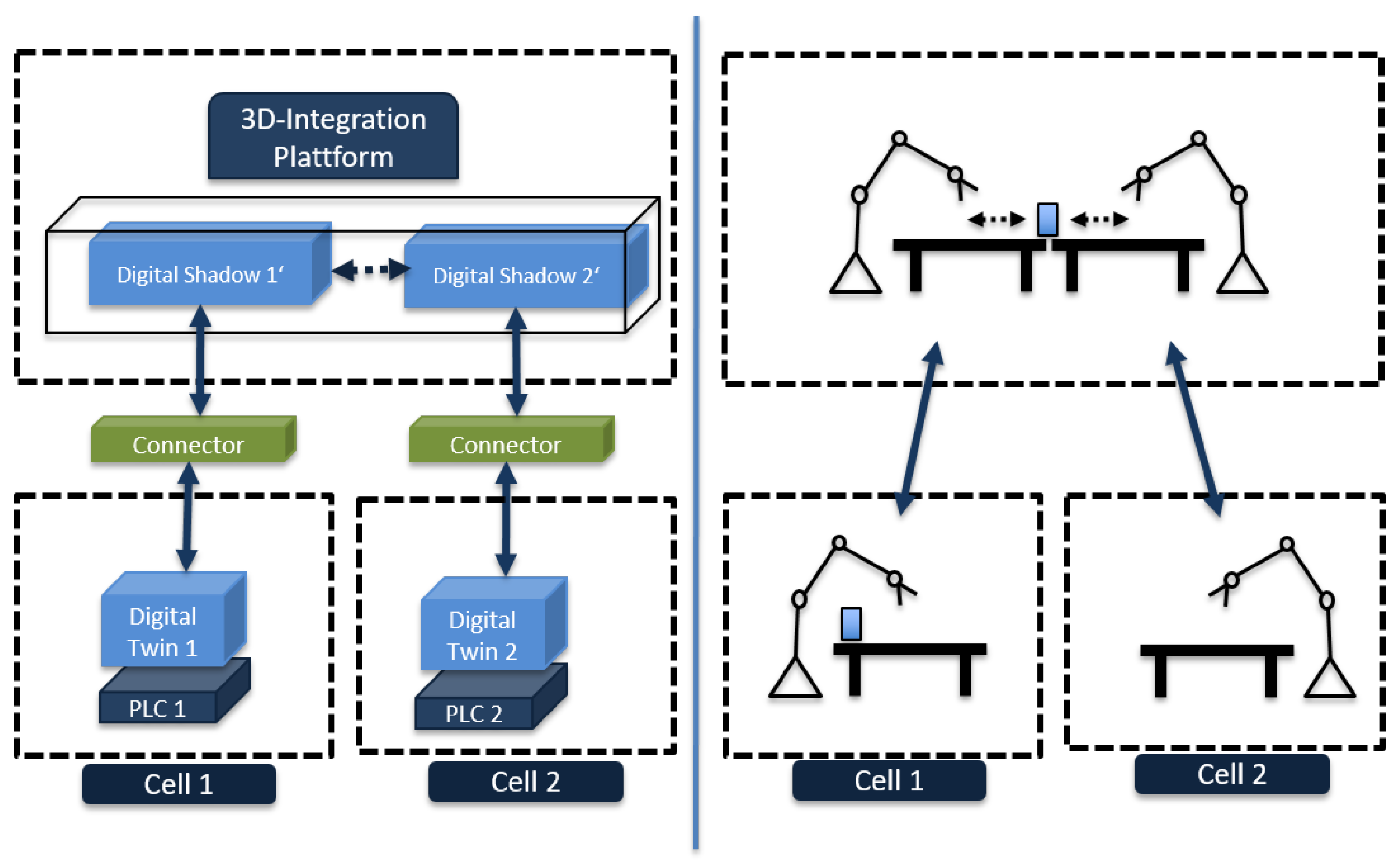
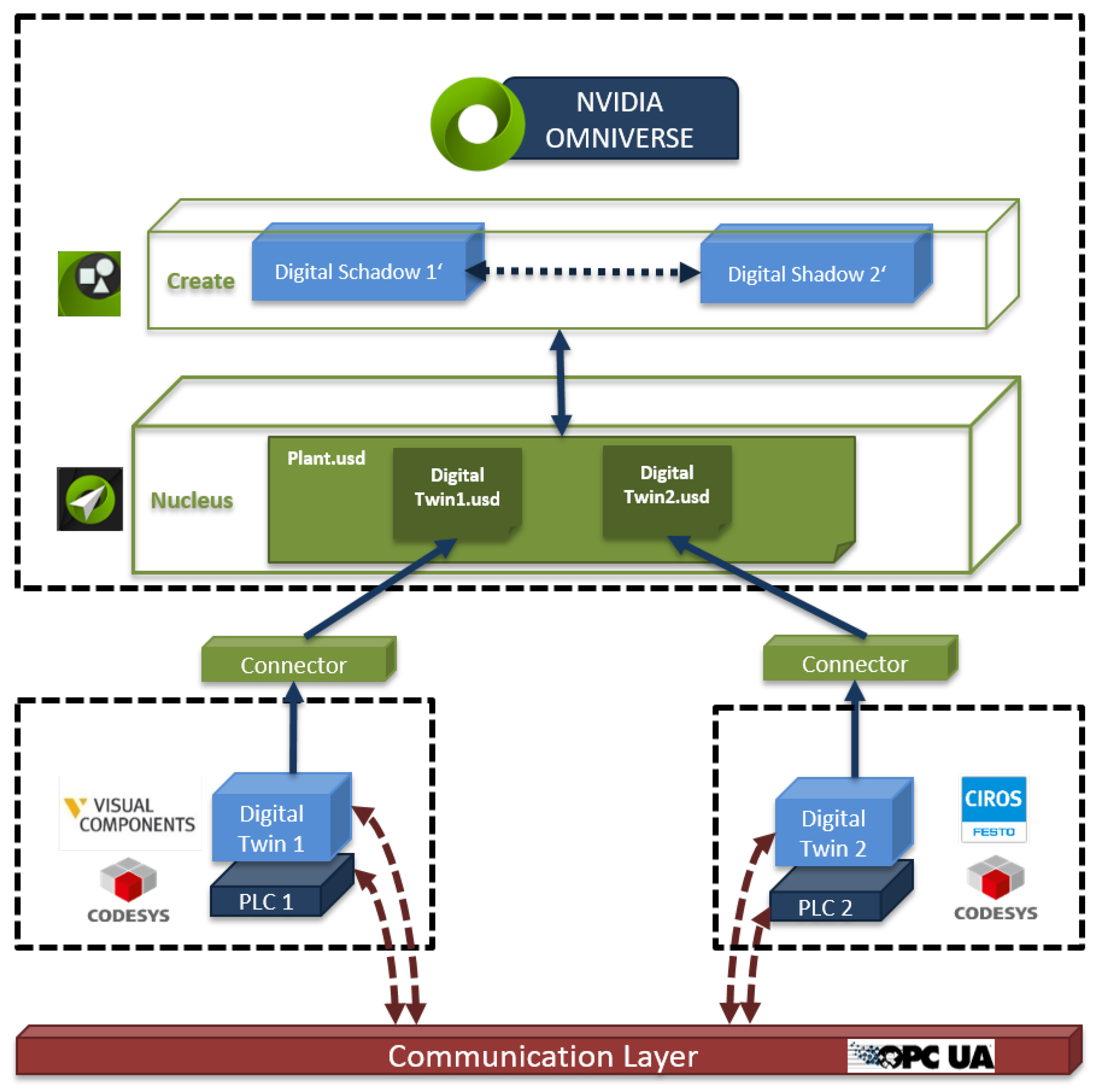
The concept shown in Figure 4 consists of two separate digital models, each controlled by a PLC. The communication between the digital modesls is implemented with OPC UA. The two PLCs act as OPC UA servers. The digital models are set up as clients. Each PLC can communicate with both clients, i.e., with both digital models. The digital model of cell 1 is created using the Visual Components software; the model of cell 2 using CIROS. The respective simulation software is connected to a higher-level data layer via a connector. The Visual Components connector already existed, whereas the CIROS connector is a prototype that was specifically developed during the course of this work in collaboration with CIROS. The connector converts the simulation output data into USD and stores the file on a server in the data layer (NVIDIA Omniverse Nucleus). The 3D integration platform (NVIDIA Omniverse Create) accesses this data and integrates the individual digital mdoels into a scene. In this concept, the connector works unidirectionally, and the scene in the 3D integration platform is referred to as digital shadows. A change in the simulation software is directly synchronised via the connector, that means the digital shadow in the 3D integration platform is constantly updated.
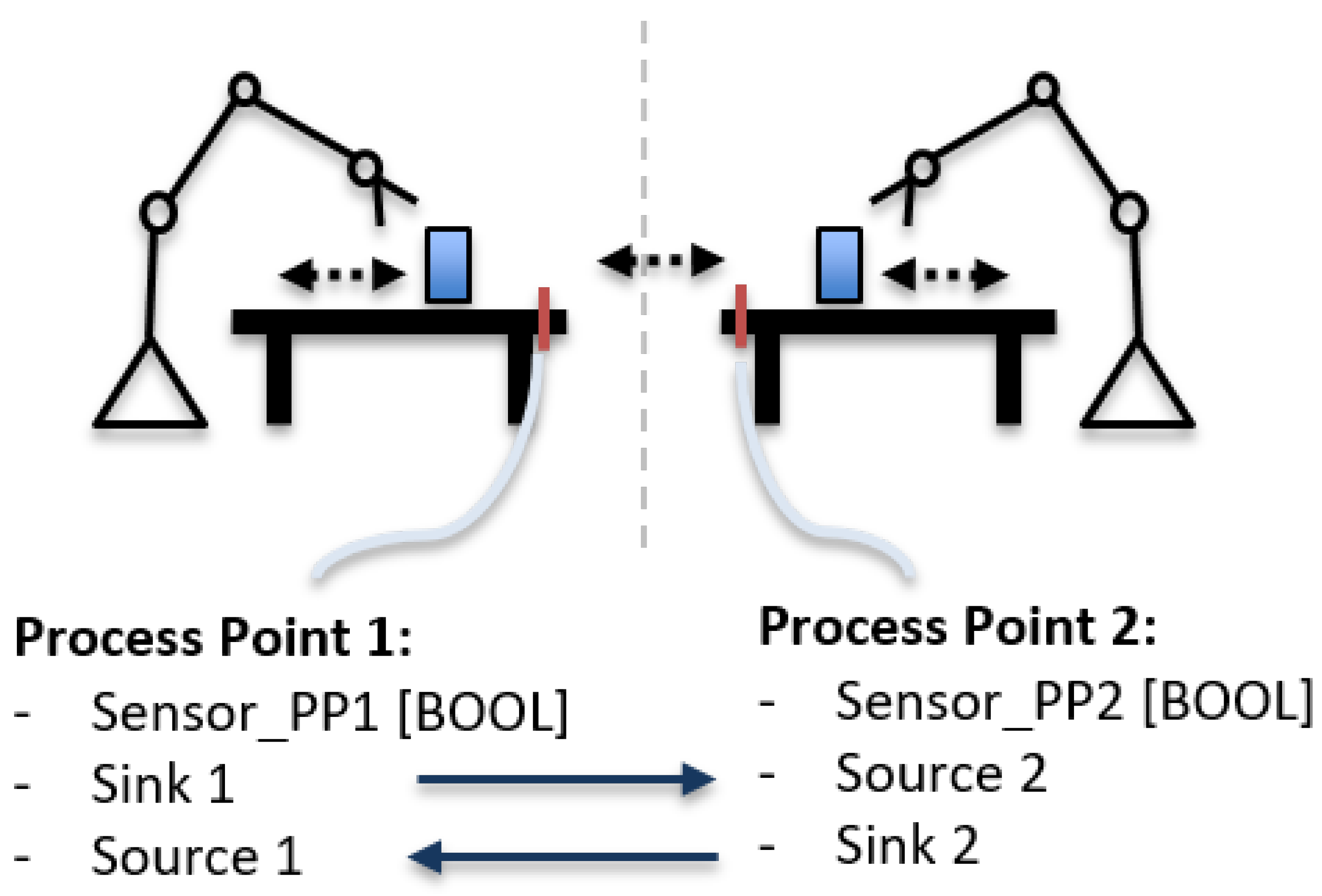
The component transfer from cell 1 to cell 2 can function via a source/sink principle, with the logic and realisation taking place in the simulation software. Figure 5 shows the “process point” at the end of each conveyor belt. This functional component contains a BOOL sensor, a source and a sink. If a component reaches the end of conveyor belt 1 of cell 1, sensor PP1 is set to HIGH. At the same time, the sink at “Process Point 1” becomes active and makes the component disappear. At the same moment, the signal sensor PP1 triggers PLC 2, which in turn triggers “Process Point 2” in system 2, where a component is directly created in its source. The two “Process Points” are later congruent in the scene in NVIDIA Omniverse, meaning that at the point where the component disappears, it is created again. This process is not visible to the human eye. A meta-communication layer is used as interface communication.
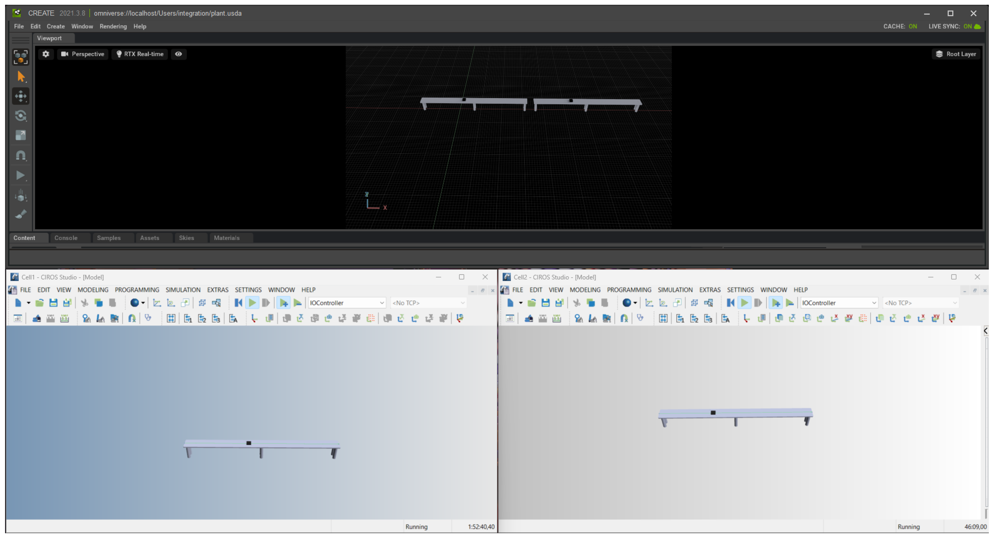
Figure 6 shows the result of Option 1. The two pictures below show cell 1 and cell 2 in the virtual commissioning software Visual Components. In the upper picture, both cells are arranged in a row in NVIDIA Omniverse Create. The generic component (a white plate) is transported from the right cell to the left cell via the conveyor belt. The individual cells and the source/sink option are controlled via two PLCs.
4.2. Option 2—Bidirectional Connector, Omniverse Extension, Apache Kafka Communication Layer
In this concept, Software in the Loop is used for controlling the digital model (Figure 7). The connector from the virtual commissioning application statically encodes the geometry to USD file and also using the live view feature in NVIDIA Omniverse. It communicates frame-to-frame changes in translation and rotation from the virtual commissioning tool to Omniverse. The connector transmits sync messages on the Apache Kafka communication layer, and the Omniverse extension developed in Python reads these sync messages and orchestrates the material flow between different cells in the integration platform. One of the major requirements for the virtual commissioning tool is that it should provide methods for creating, deleting and manipulating objects at this stage programmatically. All the required features are listed in Figure 8.
4.3. Option 3—Bidirectional Connector, Omniverse Extension
The concept shown in Option 3 (Figure 9) also uses Software in the Loop for controlling the digital model. The bidirectional connector from the virtual commissioning application provides the same functionality as described in Option 2, except for the sync messages on the communication layer. The Python Omniverse extension keeps track of the changes in the USD event stream and orchestrates the material flow between different cells.
Options 2 and 3 were implemented using a similar set-up, as shown in Figure 10. On the bottom left-hand side is a screenshot of the CIROS software (version: 7.2.0) with cell 1. A conveyor belt with a generic component is shown. On the bottom right-hand side is a similar screenshot, but with cell 2. Above, both cells are depicted as joined together in Omniverse Create.
5. Conclusions
In summary, it has been proven that it is possible to virtually commission multiple linked digital twins (in our methods digital models) from different manufacturers in a 3D integration platform with material flow monitoring between the individual cells. A comparison of the differences between all three options is shown in Figure 8.
Two findings can be determined from Option 1: First, data is lost during the transfer of the part from cell 1 to cell 2, as the part is “deleted” in cell 1 and recreated in cell 2. Planned machining data can be transferred via a comprehensive data management system. However, with a high number of variants, this becomes very complex. Secondly, for the virtual commissioning of the entire cell in NVIDIA Omniverse, the respective PLCs of the digital models twins must be run, started and saved. If the use case is scaled to 20 or more PLCs located at different sites, simultaneous simulation of all cells becomes very time-consuming.
Options 2 and 3 were implemented using a similar set-up. The difference between them lies in the underlying implementation. The major advantage of Option 2 is that it is scalable to a large number of cells, but with the disadvantage of having to modify the connector module in order to generate the sync messages, whereas the Option 3 extension needs to know the list of asset IDs in the USD file for the different cells so that the extension can control the flow of the assets accordingly, and hence that option falls behind in scalability.
By developing a bidirectional connector, the importance of bidirectional data consistency is shown. In summary, the solution is not dependent upon whether the digital model is simulated by means of Model, Software or Hardware in the Loop. However, the simulation of the entire system determines whether the effort of a complete Software or Hardware in the Loop simulation is worthwhile.
As a key result, this paper demonstrates that interaction between individual digital models from different virtual commissioning environments can be achieved with both unilateral and bilateral information exchange in NVIDIA Omniverse. Further research activities should investigate whether there are possibilities for hybrid event control for the individual modular digital twins with physical representatives. The results of the individual options tested can be methodically adapted from NVIDIA Omniverse to alternative 3D integration platforms. In addition, the question of possible advantages of other available standardized data formats such as AutomationML instead of USD will be addressed in the future.
Author Contributions
Conceptualization, M.U. and R.T.; methodology, M.U. and R.T.; software, R.T.; validation, M.U. and R.T.; formal analysis, M.U.; investigation, M.U. and R.T.; resources, M.U. and R.T.; data curation, R.T.; writing—original draft preparation, M.U.; writing—review and editing, M.U., R.T., B.L.-R. and F.H.; visualization, M.U.; supervision, B.L.-R.; project administration, M.U.; funding acquisition, B.L.-R. All authors have read and agreed to the published version of the manuscript.
Funding
This research received no external funding.
Data Availability Statement
All data used are shown in the text. Raw data are available on request.
Conflicts of Interest
The authors declare no conflict of interest.
References
- Grieves, M.; Vickers, J. Digital Twin: Mitigating Unpredictable, Undesirable Emergent Behavior in Complex Systems. In Trans-Disciplinary Perspectives on System Complexity; Kahlen, F.-J., Flumerfelt, S., Alves, A., Eds.; Springer: Cham, Switzerland, 2017; pp. 85–114. [Google Scholar]
- Weinberger, M. What is Metaverse?—A Definition Based on Qualitative Meta-Synthesis. Future Internet 2022, 14, 310. [Google Scholar] [CrossRef]
- Zheng, Z.; Li, T.; Li, B.; Chai, X.; Song, W.; Chen, N.; Zhou, Y.; Lin, Y.; Li, R. Industrial Metaverse: Connotation, Features, Technologies, Applications and Challenges. In Methods and Applications for Modeling and Simulation of Complex Systems. AsiaSim 2022; Communications in Computer and Information Science; Fan, W., Zhang, L., Li, N., Song, X., Eds.; Springer: Singapore, 2022; Volume 1712. [Google Scholar]
- Ugarte, M.; Etxeberria, L.; Unamuno, G.; Bellanco, J.L.; Ugalde, E. Implementation of Digital Twin-based Virtual Commissioning in Machine Tool Manufacturing. Procedia Comput. Sci. 2022, 200, 527–536. [Google Scholar] [CrossRef]
- Xia, L.; Lu, J.; Zhang, H.; Xu, M.; Li, Z. Construction and application of smart factory digital twin system based on DTME. Int. J. Adv. Manuf. Technol. 2022, 120, 4159–4178. [Google Scholar] [CrossRef]
- Lidell, A.; Ericson, S.; Ng, A.H. The Current and Future Challenges for Virtual Commissioning and Digital Twins of Production Lines. In Advances in Transdisciplinary Engineering; IOS Press BV: Amsterdamm, The Netherlands, 2022; Volume 21, pp. 508–519. [Google Scholar]
- Alpala, L.O.; Quiroga-Parra, D.J.; Torres, J.C.; Peluffo-Ordóñez, D.H. Smart Factory Using Virtual Reality and Online Multi-User: Towards a Metaverse for Experimental Frameworks. Appl. Sci. 2022, 12, 6258. [Google Scholar] [CrossRef]
- Magalhães, L.C.; Magalhães, L.C.; Ramos, J.B.; Moura, L.R.; de Moraes, R.E.N.; Gonçalves, J.B.; Hisatugu, W.H.; Souza, M.T.; de Lacalle, L.N.L.; Ferreira, J.C.E. Conceiving a Digital Twin for a Flexible Manufacturing System. Appl. Sci. 2022, 12, 9864. [Google Scholar] [CrossRef]
- Lin, X.; Kundu, L.; Dick, C.; Obiodu, E.; Mostak, T. 6G Digital Twin Networks: From Theory to Practice. arXiv 2022, arXiv:2212.02032v1. [Google Scholar] [CrossRef]
- Weber, K.H. Praxishandbuch mit Checklisten und Beispielen. In Inbetriebnahme Verfahrenstechnischer Anlagen, 3rd ed.; Springer: Heidelberg/Berlin, Germanyn, 2006; p. 2. [Google Scholar]
- Verein Deutscher Ingenieure e.V. VDI/VDE 3693 Blatt 1—Virtuelle Inbetriebnahme; Tech. Rep.; Verein Deutscher Ingenieure e.V.: Düsseldorf, Germany, 2016. [Google Scholar]
- Verein Deutscher Ingenieure e.V. VDI 4499 Blatt 2—Digitale Fabrik; Tech. Rep.; Verein Deutscher Ingenieure e.V.: Düsseldorf, Germany, 2011. [Google Scholar]
- VISUAL COMPONENTS. Visual Components 4.6. Available online: https://www.visualcomponents.com/de/produkte/ (accessed on 8 May 2023).
- FESTO. CIROS. Available online: https://impulse.festo-didactic.com/produkte/digital-gestuetztes-lernen/ciros/index.html (accessed on 8 May 2023).
- Deutsches Institut für Normung, e.V. Speicherprogrammierbare Steuerungen—Teil 3: Programmiersprachen (IEC 61131-3:2013); Deutsche Fassung EN 61131-3:2013. Available online: https://www.en-standard.eu/din-en-61131-3-speicherprogrammierbare-steuerungen-teil-3-programmiersprachen-iec-61131-3-2013-deutsche-fassung-en-61131-3-2013/ (accessed on 8 May 2023).
- Omniverse. Omniverse Platform Overview. Available online: https://docs.omniverse.nvidia.com/plat-omniverse/plat-omniverse/overview.html (accessed on 8 May 2023).
Figure 1.
Model in the Loop, Software in the Loop, Hardware in the Loop.

Figure 2.
Python snippet to create USD file, generated USD file and its rendering.

Figure 3.
Conceptual design.

Figure 4.
Option 1—unidirectional connector, controlled by an emulated PLC. Red dotted arrows represents the communication data flow, blue arrows the geometry data flow and the blue dotted arrow the interaction.
Figure 4.
Option 1—unidirectional connector, controlled by an emulated PLC. Red dotted arrows represents the communication data flow, blue arrows the geometry data flow and the blue dotted arrow the interaction.

Figure 5.
Sink/source-solution with process points.

Figure 6.
Result, the two screenshots below are Cell 1 and Cell 2 in Visual Components, the upper screenshot shows the integration of both cells in NVIDIA Omniverse Create.
Figure 6.
Result, the two screenshots below are Cell 1 and Cell 2 in Visual Components, the upper screenshot shows the integration of both cells in NVIDIA Omniverse Create.

Figure 7.
Option 2—bidirectional connector, Python extension, controlled by an Apache Kafka communication layer. Red dotted arrows represents the communication data flow, blue arrows the geometry data flow and the blue dotted arrow the interaction.
Figure 7.
Option 2—bidirectional connector, Python extension, controlled by an Apache Kafka communication layer. Red dotted arrows represents the communication data flow, blue arrows the geometry data flow and the blue dotted arrow the interaction.

Figure 8.
Enumeration of all required features.

Figure 9.
Option 3—bidirectional connector, Python extension. Red dotted arrows represents the communication data flow, blue arrows the geometry data flow and the blue dotted arrow the interaction.
Figure 9.
Option 3—bidirectional connector, Python extension. Red dotted arrows represents the communication data flow, blue arrows the geometry data flow and the blue dotted arrow the interaction.

Figure 10.
Result, the two screenshots below are Cell 1 and Cell 2 in CIROS Studio, the upper screenshot shows the integration of both cells in NVIDIA Omniverse Create.
Figure 10.
Result, the two screenshots below are Cell 1 and Cell 2 in CIROS Studio, the upper screenshot shows the integration of both cells in NVIDIA Omniverse Create.

Disclaimer/Publisher’s Note: The statements, opinions and data contained in all publications are solely those of the individual author(s) and contributor(s) and not of MDPI and/or the editor(s). MDPI and/or the editor(s) disclaim responsibility for any injury to people or property resulting from any ideas, methods, instructions or products referred to in the content. |
© 2024 by the authors. Licensee MDPI, Basel, Switzerland. This article is an open access article distributed under the terms and conditions of the Creative Commons Attribution (CC BY) license (https://creativecommons.org/licenses/by/4.0/).
Share and Cite
MDPI and ACS Style
Ullrich, M.; Thalappully, R.; Heieck, F.; Lüdemann-Ravit, B. Virtual Commissioning of Linked Cells Using Digital Models in an Industrial Metaverse. Automation 2024, 5, 1-12. https://doi.org/10.3390/automation5010001
AMA Style
Ullrich M, Thalappully R, Heieck F, Lüdemann-Ravit B. Virtual Commissioning of Linked Cells Using Digital Models in an Industrial Metaverse. Automation. 2024; 5(1):1-12. https://doi.org/10.3390/automation5010001
Chicago/Turabian StyleUllrich, Marco, Rashik Thalappully, Frieder Heieck, and Bernd Lüdemann-Ravit. 2024. "Virtual Commissioning of Linked Cells Using Digital Models in an Industrial Metaverse" Automation 5, no. 1: 1-12. https://doi.org/10.3390/automation5010001