Article

Building an Educational Automated Mechatronics-Based Sorting System

Department of Mechanical, Industrial and Systems Engineering, University of Rhode Island, Kingston, RI 02881, USA
*
Author to whom correspondence should be addressed.
Automation 2024, 5(3), 297-309; https://doi.org/10.3390/automation5030018
Submission received: 11 June 2024 / Revised: 11 July 2024 / Accepted: 12 July 2024 / Published: 15 July 2024

Abstract

:
This paper discusses the development of an automated sorting machine designed as a comprehensive mechatronics educational project. The project integrates mechanical and electrical design, incorporating a robot arm, a microcontroller, sensors, and actuators. The sorting machine uses color identification to sort wooden blocks of three different colors. The blocks are stacked and dropped onto a conveyor belt by a hopper system that employs a solenoid actuator and a servo to release one block at a time at specific intervals. As the belt runs continuously, each block passes under a color sensor, which monitors the color and signals one of three servo-powered mechanical arms to guide the block into the appropriate chute. Each chute is equipped with a capacitive proximity sensor that sends a voltage signal to the robot controller, queuing commands for the robot to pick up the blocks from the bottom of each chute and return them to the hopper to form a continuously running sorting system. This paper details the design and integration of the system’s various elements and the development of the control software. The designed system can drop blocks every 8.05 s, sort each block within 5 s of being sensed, and return them to the sorting system every 12 s. It has a color-sensing accuracy of 97%, with a failure rate of around 7%. The system achieved quick and reliable sorting using various low-cost, accessible, and open-source parts. The project exemplifies a cost-effective solution suitable for mechatronics education, demonstrating the numerous challenges involved in developing automated sorting systems.

1. Introduction

Automated systems are increasingly prevalent across various industries such as manufacturing, agriculture, construction, and healthcare. In manufacturing, these systems handle tasks like managing raw materials [1], packaging [2], welding [3,4], and assembly [5,6], with minimal human interaction. As the field of robotics and automation expands, the demand for skilled professionals continues to grow, especially in the niche area of mechatronics [7] that bridges mechanical and electrical engineering.
In the rapidly evolving field of mechatronics, educational projects are increasingly vital, providing students not only with practical hands-on experience but also with a deep understanding of how to integrate mechanical, electrical, and control systems. The widespread availability of open-source microcontroller platforms, such as Arduino, has significantly democratized access to the tools necessary for a myriad of automation projects. These projects span a diverse range of applications including home automation [8], agriculture [9], waste recycling [10], and water quality monitoring [11], fostering innovation across various sectors. This paper delves into the development of an automated sorting system that employs these accessible technologies. By discussing the design, implementation, and outcomes of this system, this paper highlights the educational benefits and practical applications of integrating mechatronics principles in a real-world project.
Sorting systems are fundamental components in the manufacturing sector and are extensively utilized across a variety of industries, including automotive [12], pharmaceutical [13], electronics [14], food and beverage [15], and recycling [16]. These systems streamline processes by automatically organizing items based on specific criteria such as size, shape, color, or material type, significantly enhancing efficiency and productivity in production lines. Recently, the design of a multisensor cyber–physical sorting system (CPSS) based on Industry 4.0 principles has been proposed [17]. The architecture of the proposed CPSS allows for the integration of additional sensors, increasing interoperability with upcoming sensing devices used in the sorting of different materials.
Most automated sorting systems are equipped with a set of basic components that ensure their efficient operation across various applications. The core of the system starts with the input system, often incorporating hoppers that load and regulate the flow of items onto conveyors or feed mechanisms. These items then pass through sensors and scanning technologies, such as optical, X-ray, or infrared sensors, which are crucial for identifying and classifying items based on predefined attributes like size, weight, and material. The data collected by these sensors are processed by a control system, which employs algorithms to direct the sorting mechanisms. These mechanisms might include robotic arms, air jets, flaps, or pushers, which physically separate and direct items into different channels or bins according to their classifications. Finally, an output system manages the distribution of these sorted items to their next destination, whether for further processing, packaging, or storage.
In this paper, we describe the design, control, and operation of an educational sorting system that includes the same basic components as automated industrial sorting systems (hopper, sensors, conveyor, control system, and chutes). Additionally, we employed a small robot to pick up the sorted items and return them to the hopper to achieve a fully automated, continuously running system. Unlike industrial sorting machines, which prioritize speed, accuracy, and robustness but are typically sophisticated and costly, our project focuses on simplicity and cost effectiveness, making it ideal for educational settings. Our machine employs color sensors to identify and sort wooden blocks into three categories based on color. It features a microcontroller, sensors, actuators, a robotic arm, and a conveyor system. The blocks are manually placed into a hopper, which schedules their release onto a conveyor belt where they are sorted and then recirculated back to the hopper using the robotic arm. This design emphasizes simplicity and cost effectiveness while still providing a robust platform for students to learn and experiment with various mechatronic components and principles.
This paper discusses the development and testing of this automated sorting system, which exemplifies how mechatronic skills can be applied in a fully automated system on a smaller scale, suitable for either an independent study or a course project. The primary value of the reported work lies in its ability to bridge the gap between theoretical mechatronics education and practical application. By offering a low-cost, comprehensive educational project, this work enables students to directly apply theoretical concepts in a tangible setting. The detailed discussion of the design, integration, and control software development not only contributes to the field of mechatronics education but also serves as a valuable resource for educators and students. This approach not only provides insights into the challenges and solutions encountered in developing an automated system but also enhances the educational experience by closely aligning academic learning with real-world applications.
The remainder of this paper is organized as follows: Section 2 details the design of the system, including its mechanical, electrical, and software components. Section 3 discusses the validation of the system, testing results, and improvements. Concluding remarks are provided in Section 4.

2. Materials and Methods

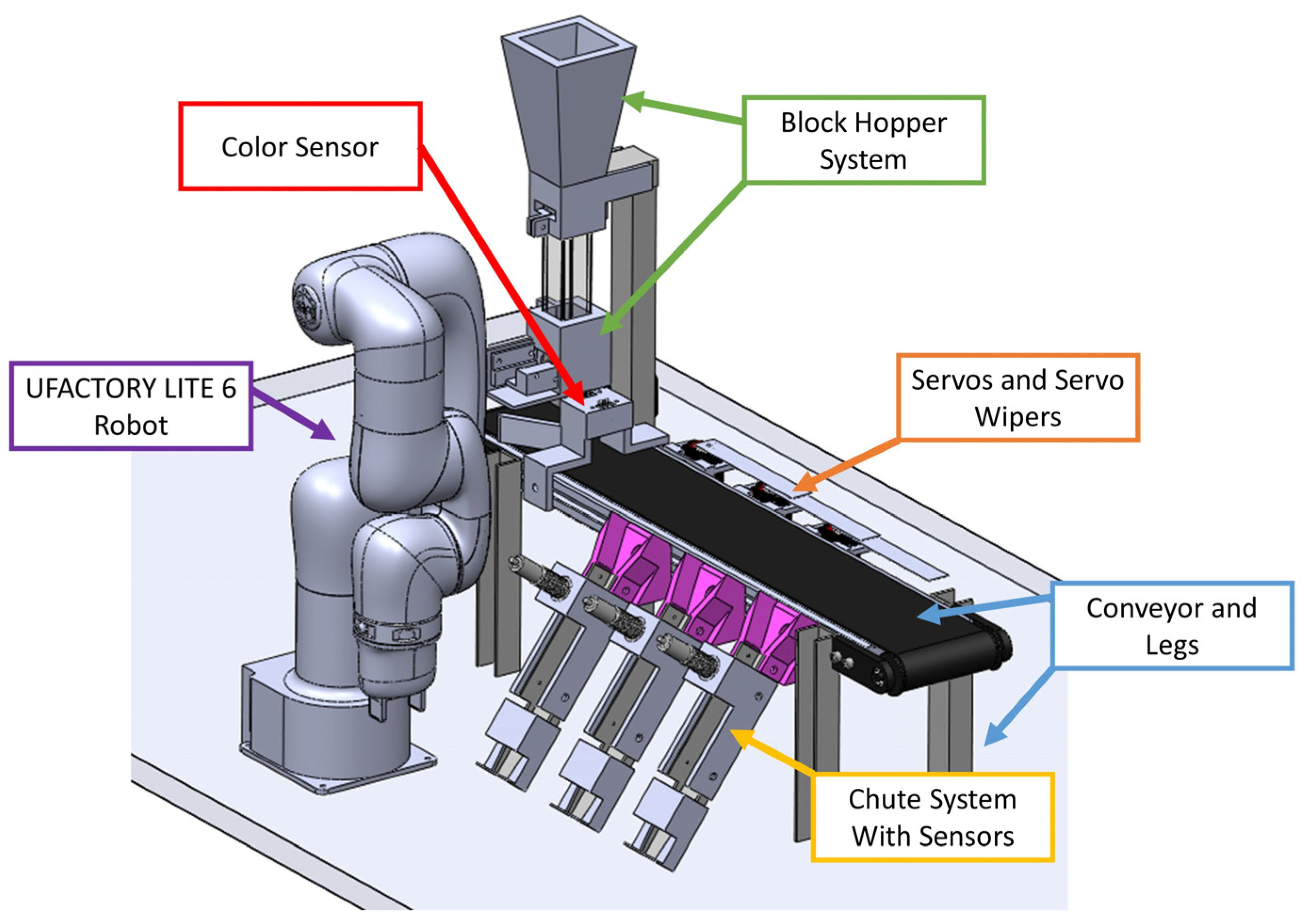
2.1. Mechanical Design

Figure 1 shows a CAD model of the automated sorting system. The system consists of six main subsystems. These are the robotic arm with a gripper to pick up the blocks, the block hopper system, the stepper-motor-driven conveyor belt, the color sensor, the servos with the servo wipers, and the chutes with the sensors. Both the robot and the conveyor belt are commercially available systems. No changes were made to the arm for use in this project. For the conveyor belt system, the system was elevated a certain height above the support table to allow for the mounting of the chutes. Below are details on the design of the remaining four subsystems, which were custom-made for this application.

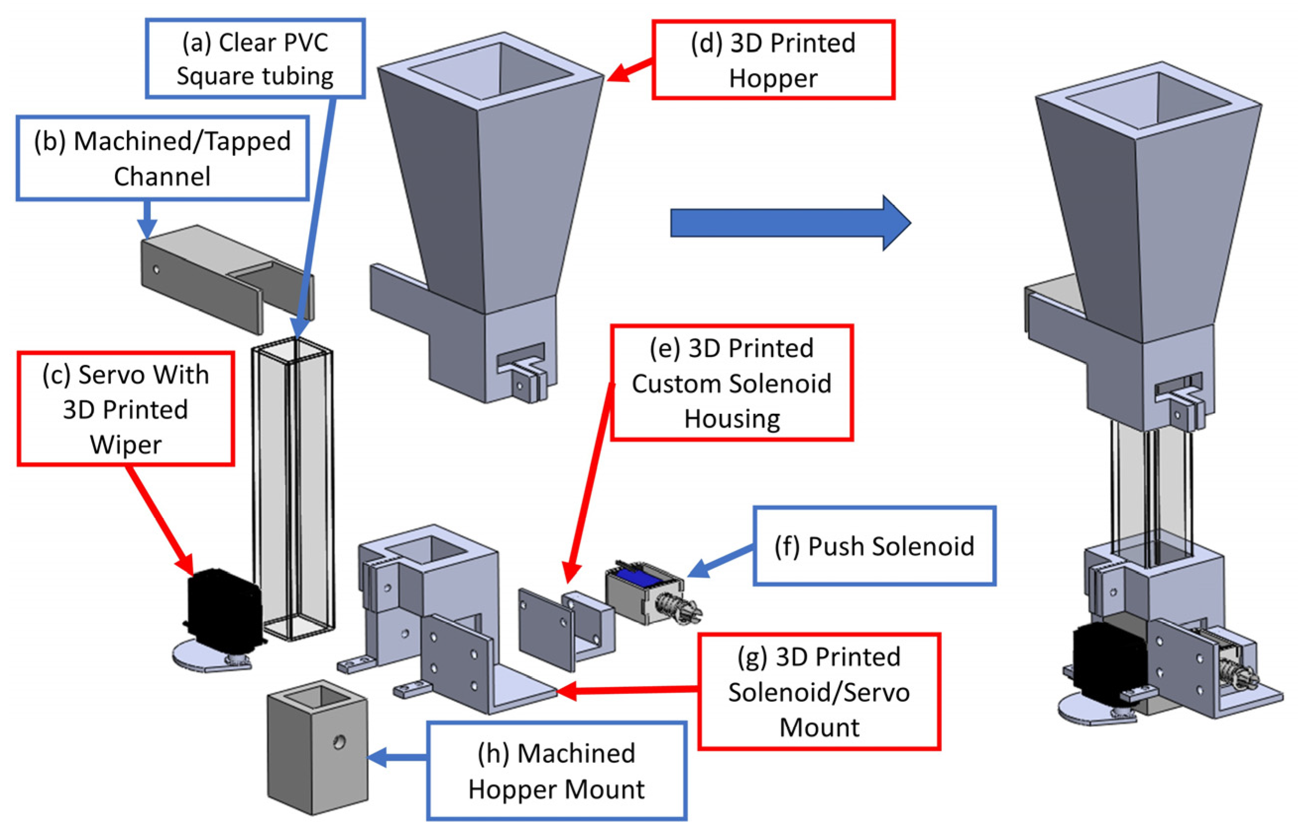
2.1.1. Hopper System Design

The purpose of the block hopper system is to feed the blocks onto the top of the conveyor belt at a user-specified rate. At the start of this system, the user will manually drop the blocks into the hopper. Later, these blocks will be automatically picked up and dropped into the hopper by the robotic arm. The hopper design consists of a mix of aluminum machined parts, clear square plastic tubing, and specially designed 3D-printed parts. Figure 2 shows an exploded view of the hopper design. The top portion of the hopper shown in Figure 2d has a cone-style design to allow the blocks to slide down and form a single-column stack within the hopper. The clear tubing shown in Figure 2a allows the user to see whether the blocks are stacked correctly within the hopper. A combination of a push-type solenoid and a rotating door actuated by a servo shown in Figure 2f,c, respectively, controls the flow of blocks from the hopper. To drop a block from the hopper, the solenoid is actuated to apply a holding force on the second block from the bottom of the stack. Then, the rotating door is opened to allow the bottom block to drop. Once the block is dropped, the door is closed, and the solenoid is released to allow all the blocks to move down.

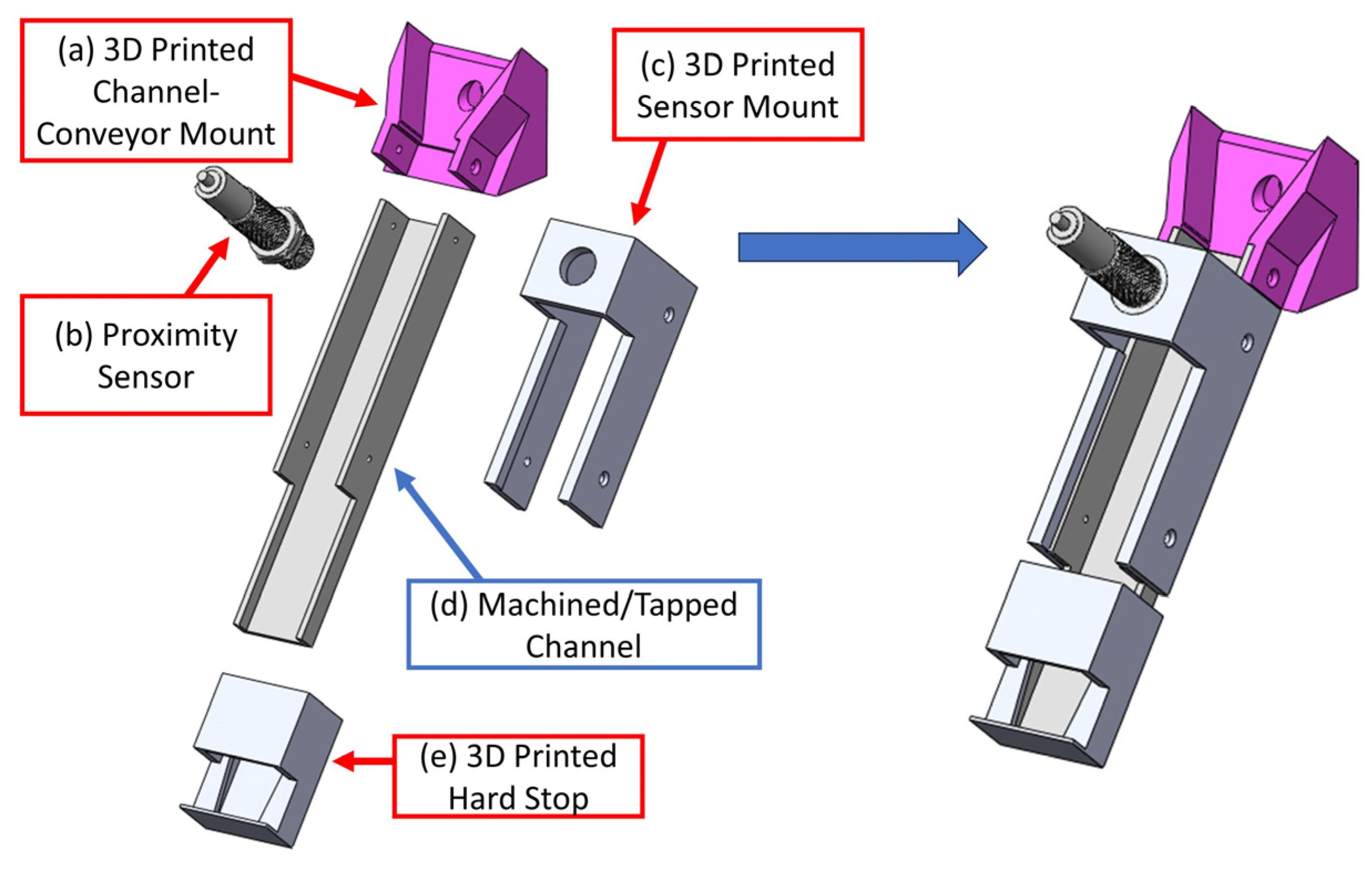
2.1.2. Sorting System Design

The block color sorting system consists of three subsystems: chutes for sorting the blocks, a servo wiper that pushes the blocks into the chutes, and a color sensor mounted on the conveyor belt. Together, these subsystems detect the color of the blocks and sort them into designated areas.
The chute is specifically designed to stack the sorted blocks for the robot to pick up. It incorporates a proximity sensor that signals the robot when to pick up a block. Figure 3 provides an exploded view of this subsystem. As shown in Figure 3a, the chute features a 3D-printed, tapered part that guides each block from the conveyor belt into the chute holder and mounts on the machined channel (see Figure 3d). The angle of the part is 53 degrees, calculated using basic trigonometry based on the height of the conveyor belt. This design ensures the chute is structurally stable and allows blocks to quickly and efficiently fall into it due to gravity. The capacitive proximity sensor, displayed in Figure 3b, is mounted at the top of the chute to detect each block as it passes. The sensor’s 3D-printed mount (Figure 3c) is affixed to the aluminum channel, positioning the sensor optimally for block detection. Lastly, a sliding piece at the bottom of the chute, shown in Figure 3e, stops the blocks. This 3D-printed part features a cover that reveals only one block at a time, preventing the robot from picking up multiple blocks simultaneously due to the increased normal force and the resultant friction from stacked blocks.
The servo wipers are engineered to push blocks into their respective chutes. Each servo is attached to a 3D-printed part that includes a channel, enabling height adjustment relative to the belt, as illustrated in Figure 4a. This feature is critical because the servo wipers, which direct the blocks into the chutes, are stacked due to their length, as shown in Figure 4b. Therefore, the ability to adjust the height is essential and was incorporated into the design of the servo mount.
The color sensor assembly is shown in Figure 5. It uses the TCS3200/TCS230 color sensor for color detection. The sensor is mounted on a 3D-printed part that not only guides the blocks to center them but also positions the sensor above the blocks as they pass underneath. This color sensor emits white light and captures red, green, and blue values using separate photodiodes. It then sends these readings as digital pulses back to the Arduino.

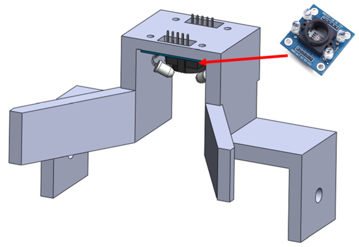
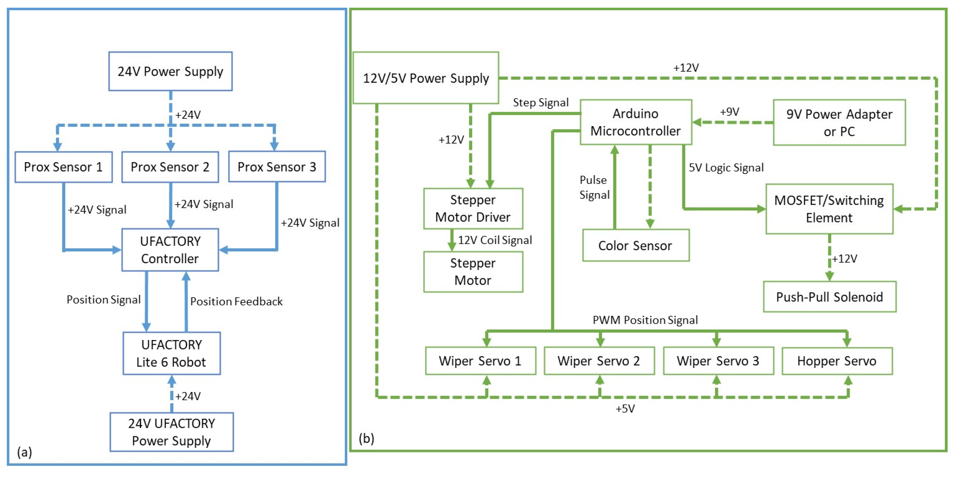
2.2. Electrical Design

Overall, the sorting machine consists of two electronically isolated systems that physically interact to form a larger integrated system. The block diagram shown in Figure 6 illustrates the interactions between the different components. Figure 6a details the robot controller system, while Figure 6b outlines the Arduino-based sorting system.
The system depicted in Figure 6a is responsible for sending digital signals to the robot controller from the capacitive proximity sensors. These signals provide instructions for the robot to move and pick up blocks. A 24 VDC power supply energizes the sensors, and the controller’s I/O capabilities interpret these signals within a program, directing the robot to specific positions to retrieve blocks from their respective chutes. Additionally, the robot’s movement and control capabilities are powered by a separate 24 VDC supply. The robot controller and software are accessible through a hardwired LAN connection, allowing any PC on the same network to interface with the robot and its software.
Figure 6b shows the Arduino-based system that manages the conveyor belt, servos, solenoid, stepper motor, and color sensor. The power supply for this system delivers 12 VDC to the solenoid and stepper motor, both of which are connected to the Arduino via control drivers—a MOSFET for the solenoid and a stepper motor driver for the stepper motor. Additionally, the power supply provides 5 VDC to operate the servos, which receive PWM control signals from the Arduino. These signals coordinate the movement of the blocks into the chutes and their placement on the belt from the hopper. Despite the system’s complexity, using a single Arduino UNO to control all components simplifies the implementation.

2.3. Software Implementation
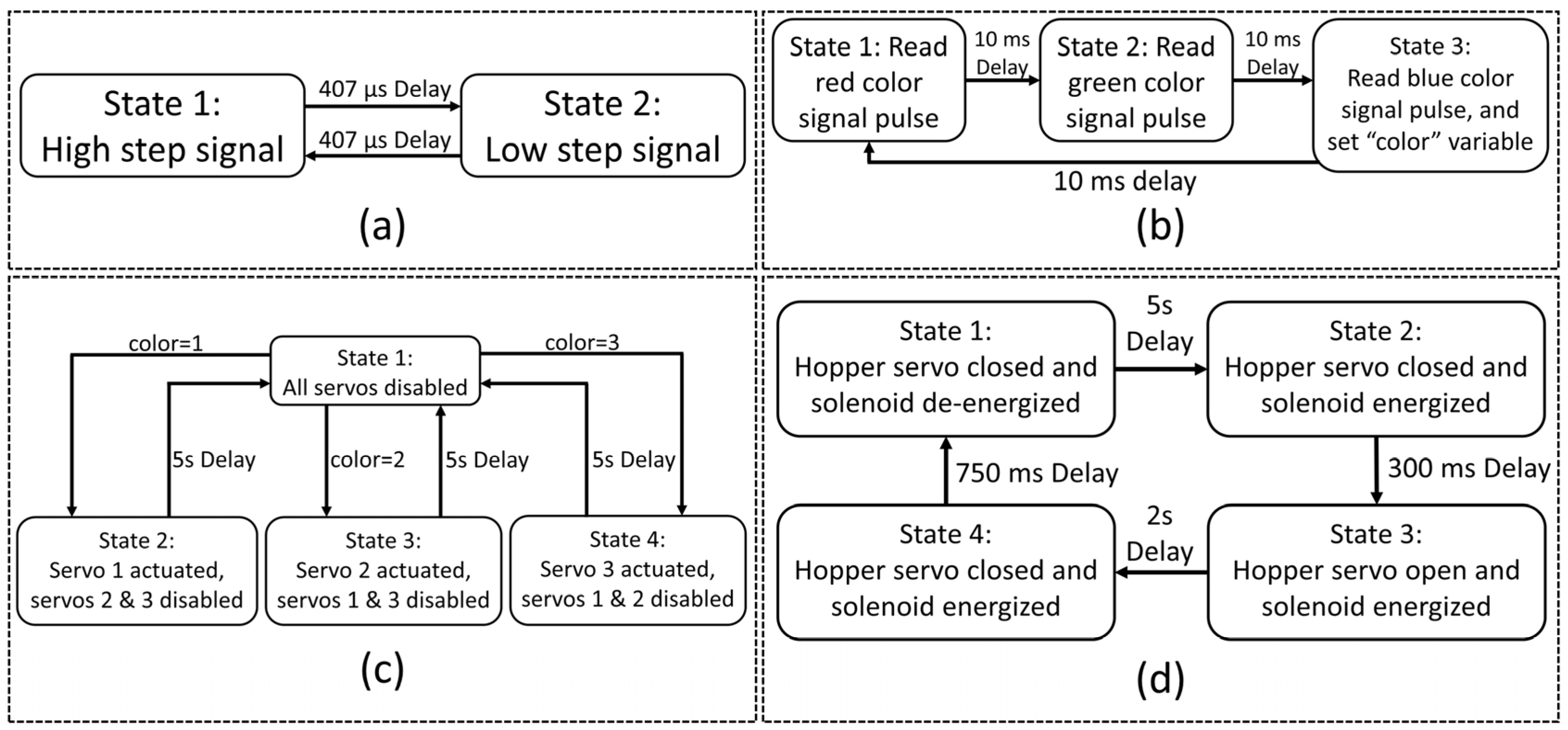
The software implementation is a crucial aspect of this project, ensuring that the system functions effectively. This project relies on two major software components: the control software for the Arduino microcontroller and the control software for the robot.

2.3.1. Arduino Code

The code for the Arduino microcontroller is structured using a task–state control software structure (refer to [18] (pp. 162–174) for more details). Each of the four subsystems controlled by the Arduino—namely the stepper motor, color sensor, servo wipers, and hopper—has its control task. Each task’s code is divided into several mutually exclusive states, avoiding any blocking code. This approach avoids the use of the ‘delay’ command in Arduino, instead relying on the built-in timers in the Arduino platform to perform any timing or delay operations. The tasks operate in what is known as the cooperative multitasking mode. In this mode, each task is included in a loop that is executed repeatedly. Tasks are activated sequentially based on their order in the loop. Upon activation, a task cycles through its states, identifies the current state, executes the corresponding code, and then exits. During each loop cycle, only the current state of each task is executed. The state-transition diagrams for the four control tasks are shown in Figure 7 and are explained below.
Stepper Motor Task (Figure 7a): The stepper motor that moves the conveyor belt is controlled through a program that alternates between two states. One state sends a high +5 V logic signal to the stepper driver, and the other sends a low 0 V signal, switching every 407 μs based on tested values to optimize the belt speed.
Color Sensor Task (Figure 7b): This task continuously reads the color of the object beneath the sensor using the Arduino’s built-in ‘pulseIn’ function. The sensor switches the color it reads every 10 ms in each new state. In the third state, it updates a ‘color’ integer variable that instructs the servo wiper task on which servo to activate. Thus, the latency between the start of sensing and the determination of the color is 30 ms.
Servo Wiper Task (Figure 7c): Initially, all servos remain in their home position, waiting for the ‘color’ variable to change. The servo arm is actuated immediately after the color is determined. Depending on the color detected as blocks pass by, one of the three servos is activated, corresponding to the states 2, 3, and 4. After a 5 s delay, the servo wipers return to their home position.
Hopper Cycle Task (Figure 7d): This four-state task manages the dropping of blocks through the hopper servo and solenoid actuator shown in Figure 2. The cycle begins in state 1, waits 5 s, actuates the solenoid, opens the servo door for 300 ms to drop a block, closes the servo after 2 s, and de-energizes the solenoid after a 750 ms delay before repeating the cycle. Timing functions are used to avoid blocking code.
Each of these tasks is carefully timed and coordinated to ensure the efficient operation of the sorting machine, illustrating the complex interplay of hardware and software in automated systems.

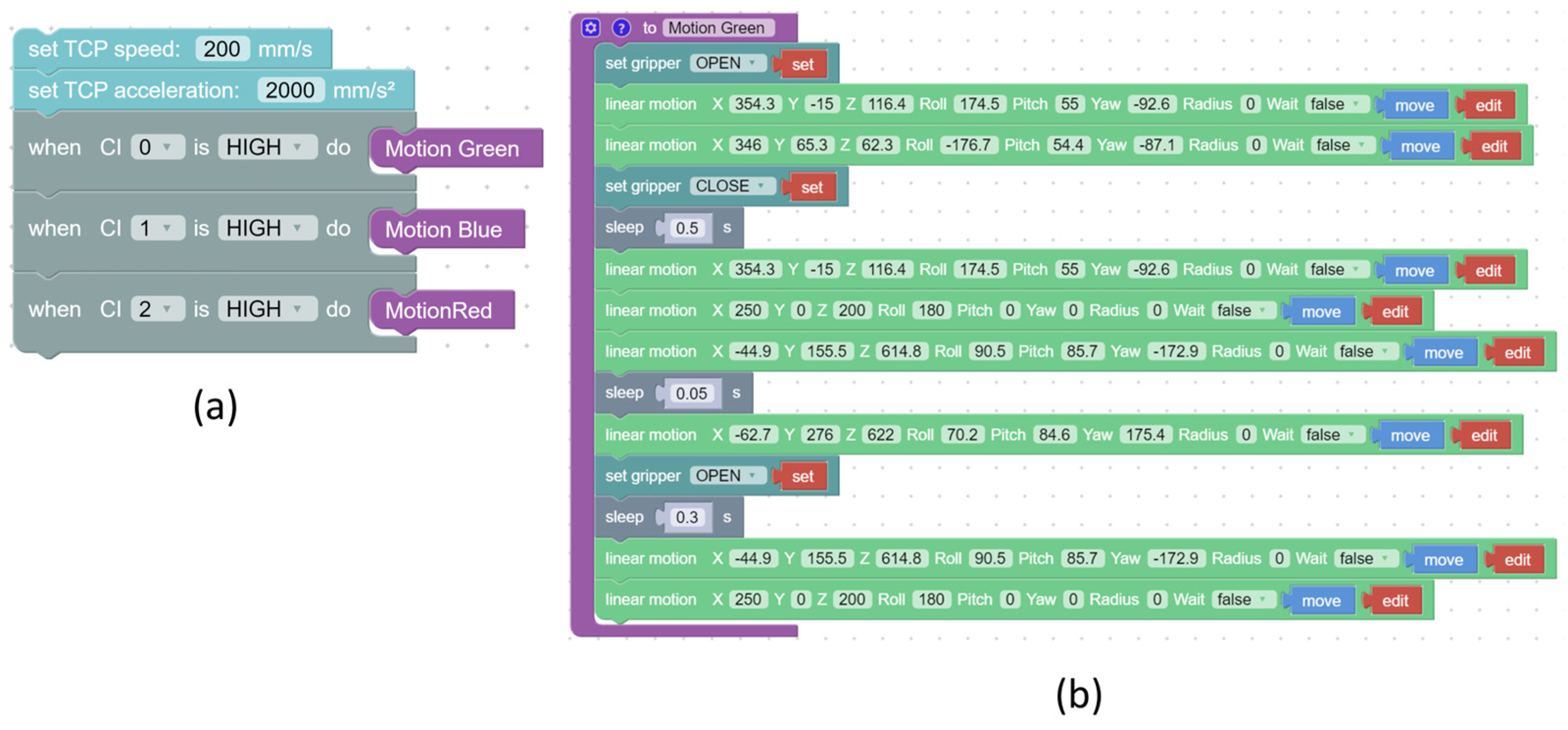
2.3.2. UFACTORY Software/Robot Program

The robot program uses UFACTORY software (Version 1.01), which includes a Bockly editor for integrating robot functions that automatically convert into a Python program. This feature facilitates easy programming and path mapping for the robot. The program is straightforward: it initializes the robot’s movement parameters and includes three event triggers. These triggers activate when a signal from a configurable input on the controller is recognized, each triggering a specific movement function associated with a chute and sensor.
Each of the three event triggers corresponds to a specific movement function that directs the robot’s gripper along a pre-planned path. This path is configured using a linear movement block where the coordinates are set. Additionally, the program uses a timer for delays and a block to open and close the gripper. A significant advantage of this Blockly programming is its non-blocking nature. Events are queued and executed even if the robot is already in motion from a previous trigger. This ensures that movements are queued regardless of the quantity or sequence of blocks passing by the sensors.
Figure 8a illustrates the main program, which utilizes event triggers from the robot controller and sensors to queue instructions to the robot based on digital inputs. When a sensor detects a block, it creates an event that causes the robot to execute a set of movement steps within a function dedicated to picking up the detected block. An example of such a function for a green block is shown in Figure 8b. The movement functions for the red and blue blocks are similar, only differing in the specific linear motion points. The paths between the chutes and the hopper share intermediate points for all three colors, streamlining the programming and execution process.

3. Results and Discussion

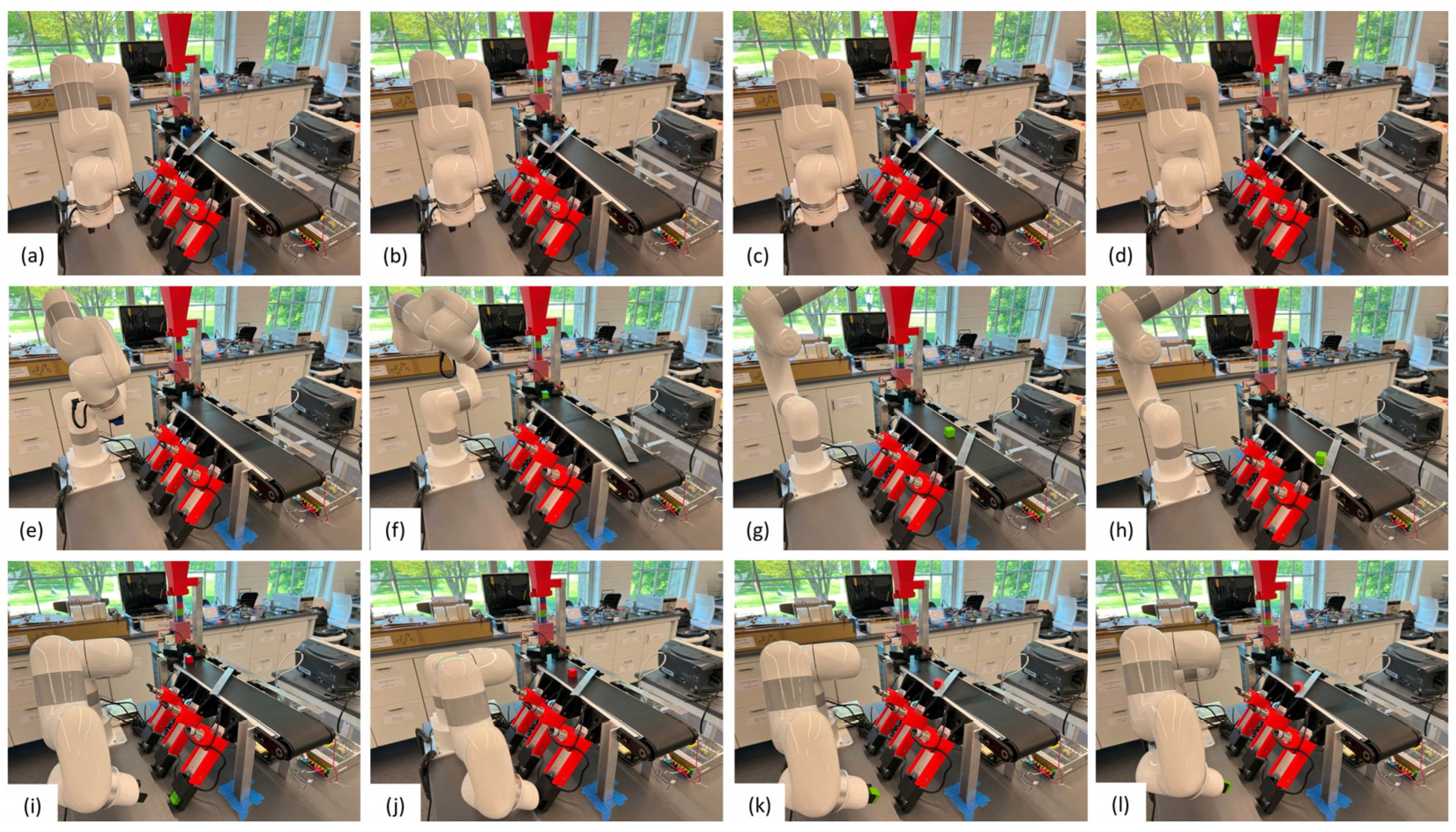
3.1. System Validation

Figure 9 illustrates the robot in action, sorting three blocks of different colors, showcasing the coordination of all moving parts. Initially, the blocks are manually loaded into the hopper, and the system is powered on. Notice the stack of multicolored blocks visible in the clear section of the hopper. The details of the sorting process are described below.
Figure 9a: The first blue block drops; the color sensor detects it as blue, and the corresponding servo pushes the block into its chute. This process is detailed in Figure 9b–d.
Figure 9e–h: The robot grips the blue block (Figure 9e), moves upward, and deposits it back into the hopper (Figure 9f–h). Simultaneously, a green block drops onto the belt.
Figure 9h: The color sensor identifies the green block, which then hits the servo wiper and falls into its chute. While the green block is being sorted, the robot returns to its home position.
Figure 9i,j: The robot moves to pick up the newly sorted green block (Figure 9i), and Figure 9j shows the green block being picked up by the robot.
Figure 9k,l: The robot successfully retrieves the green block from the chute. Concurrently, the red block passes under the color sensor, triggers the corresponding servo wiper, and is pushed into its designated chute (Figure 9k,l).
This sequence repeats continuously, with blocks being sorted and then reinserted into the system in their sorted order, demonstrating the system’s integrated operation and its capability for continuous automation.

3.2. Block Specimens

In this project, 1-cubic-inch unfinished wooden blocks were used. However, most components, including the clear tubing and the hopper mount, were designed for 1-square-inch clearances. This proved insufficient for the blocks to move freely through the system. Consequently, we resized each block to be 0.9 cubic inches to ensure they could pass through smoothly. The system’s design, including the 3D-printed stops at the chutes’ ends, accommodated this smaller block size. Due to variations from machining and sanding, the blocks lacked precise uniformity in size. To prepare the blocks for painting, we sanded them to a smooth finish, enhancing their glossiness. This glossiness is crucial for the effectiveness of the color sensor, as it reflects the sensor’s light more intensely onto its photodiodes. However, blocks with any unsanded surfaces were sometimes not recognized by the sensor or were misidentified. Figure 10 illustrates the reflective difference between a finished and an unfinished block surface.

3.3. Testing and Results

Testing was conducted to evaluate the performance of the sorting mechanism. The system was capable of replacing a block every 12 s, a rate limited by the robot’s speed and its efficiency in reintroducing the blocks. Each test lasted 15 min. With a sorting rate of one block every 12 s, the system managed to process approximately 5 blocks per minute, totaling 75 blocks sorted in each 15 min session. Table 1 presents the results of two such tests, detailing the system’s performance and the faults observed. Table 2 lists the causes of these faults along with potential solutions.

3.4. Performance Metrics

Table 3 lists the performance metrics for the developed system. The system had a color sensing accuracy of about 97% (4 color sorting errors out of 150), a processing rate of 5 blocks per minute based on a robot cycle time of 12 s per block, and a fault rate of 6.7% (10 faults per 150 blocks). Note that the fault rate includes the color sorting error, although this error does not cause a stoppage of the system.

3.5. Discussion

In the development and building of this automated sorting system, the focus was primarily on refining the physical design and improving its performance. We discuss below some of the issues and challenges we addressed.

3.5.1. Physical Design Adjustments

Initially, the 3D-printed mount connecting the chutes to the conveyor had a narrow opening, causing blocks to jam if not perfectly aligned. The redesign extended the mount and widened the opening, allowing blocks to self-correct their orientation upon entry. Additionally, the hopper faced challenges with the solenoids responsible for exerting a normal force on the blocks. After testing three different solenoids, we settled on a 12 VDC model drawing a current of 1.8 A and exerting a force of 25 N, which balanced the power consumption and the operational efficiency effectively. A fixture redesign, as shown in Figure 2g, facilitated the integration of the new solenoid without necessitating a complete part reprint, thus saving costs and time.

3.5.2. Electronics and Switching Mechanisms

The initial use of a relay module to control the solenoid was inadequate due to the absence of a flyback diode, causing interference and servo jitter. Transitioning to MOSFETs with a flyback diode rectified this issue. We also replaced the initial IRFZ14 transistor with an IRFZ44N to better handle the current required by the new solenoid without overheating.

3.5.3. Speed of Robot vs. Dispensing Rate and Conveyer Speed

The efficiency and speed of our system depend on several factors: the timing of the robot’s collection of the blocks, the hopper’s dispensing rate, and the conveyor belt’s speed. We calibrated the conveyor belt to move slowly enough for the color sensor to accurately detect different colors as blocks pass underneath yet fast enough to transport blocks efficiently across the belt and into the chutes. According to Figure 7d, a complete cycle of the hopper occurred every 8.05 s, meaning it dispensed blocks at this interval. Additionally, there was a 5 s adjustable delay between state 1 and state 2, as seen in Figure 7d, allowing us to modify the duration of the dispensing process. Currently, the robot can only replace a block every 12 s due to its programmed path and settings, which results in blocks being sorted faster than they can be replaced.

3.5.4. Two Blocks Back to Back

It should be noted that the servo-based push mechanism was designed to handle one block at a time and not two blocks back to back. If the latter case occurs, and the two blocks have the same color, there will be no issue as they will be guided to the same chute. If the front block is green and the following block is either red or blue, there will also be no issue because the green block’s servo arm will not block the following block. However, if the front block is either red or blue and the following block is green, the green block will be blocked from reaching its chute and will be missorted. The same issue will occur if the front block is blue and the following block is red. We did not observe this error in our system, as the hopper never dropped more than one block at a time during all our testing.

3.5.5. System Cost

A feature of the developed system is the relatively low cost of this automated system. Table 4 lists the main components of this system. A detailed list of all components used in this project plus CAD drawings are available at this site: (https://github.com/pfriars14/Educational-Automation, Accessed on 11 July 2024). As seen in Table 4, the most expensive item was the robot arm (USD 3639) followed by the conveyor belt (USD 500). Many of the components used in this project or alternatives to them are commonly available in university mechatronics labs, which reduces the overall cost of the system.

4. Conclusions

This paper details the design, building, integration, and testing of an affordable, educational automated mechatronics-based system for continuously sorting and stacking colored wooden blocks. The developed project exemplifies a low-cost system that can be used in mechatronics education to illustrate the many challenges encountered in developing an automated system. The project offers training in machine and CAD design, control software development, 3D printing, wiring, and system integration. The automated sorting system has enough complexity to be assigned as a semester group project. Alternatively, components of the systems can be assigned as small projects throughout the semester, with a final integration task.
Future work on this project includes several improvements to reduce the sorting failure rate. These improvements include adjusting the chute angle to slow down the block descent, which may require redesigning the 3D-printed mounts. Enhancing sensor calibration and ensuring consistency in the block sizing and surface finish would improve the color detection accuracy. Additionally, optimizing the robot’s path and speed will reduce the time required to replace a block. Furthermore, using the ROS 2 system offers an alternative approach to developing the control software for this project as well as taking into consideration Green Information and Communication Technology (ICT) principles in the design and selection of the system components. Finally, integrating all electronics onto an Arduino Nano board and housing them within a single enclosure would streamline the design, enhancing both system troubleshooting and aesthetics. These strategies and refinements not only address the current limitations but also set the stage for future enhancements to the system’s reliability and efficiency.

Supplementary Materials

A detailed list of all components used in this project, a video demonstration of the sorting machine, and the developed code plus CAD drawings can be downloaded at https://github.com/pfriars14/Educational-Automation (Accessed on 11 July 2024).

Author Contributions

Conceptualization, B.J. and M.J.; methodology, M.J. and B.J.; software, B.J.; validation, B.J. and M.J.; formal analysis, B.J. and M.J.; investigation, M.J. and B.J.; resources, M.J.; data curation, B.J. and M.J.; writing—original draft preparation, B.J.; writing—review and editing, M.J. and B.J.; visualization, B.J.; supervision, M.J.; project administration, M.J.; funding acquisition, M.J. All authors have read and agreed to the published version of the manuscript.

Funding

This project was funded by the University of Rhode Island’s Department of Mechanical, Industrial, and Systems Engineering.

Data Availability Statement

The original contributions presented in this study are included in this article/Supplementary Material, further inquiries can be directed to the corresponding author.

Acknowledgments

The authors would also like to thank James Byrnes for helping to troubleshoot and setup equipment, and Alex Jedson for his preliminary design concepts for this system.

Conflicts of Interest

The authors declare no conflicts of interest.

References

  1. Almeida, J.M.; Martins, A.; Almeida, C.; Viegas, D.; Ferreira, A.; Matias, B.; Sytnyk, D.; Soares, E.; Pereira, R. Sustainable Exploration and Exploitation of Raw Materials. INESCTEC Sci. Soc. 2023, 1, 92–97. [Google Scholar]
  2. Khodabandehloo, K. Robotic Handling and Packaging of Poultry Products. Robotica 1990, 8, 285–297. [Google Scholar] [CrossRef]
  3. Lei, T.; Rong, Y.; Wang, H.; Huang, Y.; Li, M. A Review of Vision-Aided Robotic Welding. Comput. Ind. 2020, 123, 103326. [Google Scholar] [CrossRef]
  4. Xu, Y.; Wang, Z. Visual Sensing Technologies in Robotic Welding: Recent Research Developments and Future Interests. Sens. Actuators Phys. 2021, 320, 112551. [Google Scholar] [CrossRef]
  5. Thomas, G.; Chien, M.; Tamar, A.; Ojea, J.A.; Abbeel, P. Learning Robotic Assembly from CAD. In Proceedings of the 2018 IEEE International Conference on Robotics and Automation (ICRA), Brisbane, QLD, Australia, 21–25 May 2018; IEEE: New York, NY, USA, 2018; pp. 3524–3531. [Google Scholar]
  6. Jiang, J.; Yao, L.; Huang, Z.; Yu, G.; Wang, L.; Bi, Z. The State of the Art of Search Strategies in Robotic Assembly. J. Ind. Inf. Integr. 2022, 26, 100259. [Google Scholar] [CrossRef]
  7. Harashima, F.; Tomizuka, M.; Fukuda, T. Mechatronics—What Is It, Why and How. IEEE/ASME Trans. Mechatron. 1996, 1, 1–4. [Google Scholar] [CrossRef]
  8. Chioran, D.; Valean, H. Arduino-based smart home automation system. Int. J. Adv. Comput. Sci. Appl. 2020, 11, 67–73. [Google Scholar] [CrossRef]
  9. Yasin, H.; Zeebaree, S.; Zebari, I. Arduino based automatic irrigation system: Monitoring and SMS controlling. In Proceedings of the 2019 4th Scientific International Conference Najaf (SICN), Al-Najef, Iraq, 29–30 April 2019; IEEE: New York, NY, USA, 2019; pp. 109–114. [Google Scholar]
  10. Hassan, H.; Saad, F.; Raklan, M. A low-cost automated sorting recycle bin powered by Arduino microcontroller. In Proceedings of the 2018 IEEE Conference on Systems, Process and Control (ICSPC), Melaka, Malaysia, 14–15 December 2018; IEEE: New York, NY, USA, 2018; pp. 182–186. [Google Scholar]
  11. Hong, W.; Shamsuddin, N.; Abas, E.; Apong, R.; Masri, Z.; Suhaimi, H.; Gödeke, S.; Noh, M. Water Quality Monitoring with Arduino Based Sensors. Environments 2021, 8, 6. [Google Scholar] [CrossRef]
  12. Tu, X.; Liu, H.; Liu, Q.; Hu, W.; Liu, J.; Yao, D.; Zeng, H. Development and Application of Intelligent Bumper Matching and Sorting System. In Society of Automotive Engineers (SAE)-China Congress; Springer Nature: Singapore, 2023; pp. 1017–1033. [Google Scholar]
  13. Rapolti, L.; Holonec, R.; Grindei, L.; Viman, O. Automated Sorting of Pharmaceutical Waste Using Machine Vision Technology. In Proceedings of the 7th International Conference on Advancements of Medicine and Health Care through Technology: Proceedings of MEDITECH-2020, Cluj-Napoca, Romania, 13–15 October 2020; Springer International Publishing: Berlin/Heidelberg, Germany, 2022; pp. 409–416. [Google Scholar]
  14. Rapolti, L.; Rodica, H.; Grindei, L.; Purcar, M.; Dragan, F.; Copîndean, R.; Reman, R. Experimental stand for sorting components dismantled from printed circuit boards. Minerals 2021, 11, 1292. [Google Scholar] [CrossRef]
  15. Balabanov, P.; Divin, A.; Egorov, A.; Yudaev, V. Mechatronic System for Fruit and Vegetables Sorting. IOP Conf. Ser. Mater. Sci. Eng. 2020, 734, 012128. [Google Scholar] [CrossRef]
  16. Wahab, D.; Hussain, A.; Scavino, E.; Mustafa, M.; Basri, H. Development of a Prototype Automated Sorting System for Plastic Recycling. Am. J. Appl. Sci. 2006, 3, 1924–1928. [Google Scholar] [CrossRef]
  17. Konstantinidis, F.; Sifnaios, S.; Tsimiklis, G.; Mouroutsos, S.; Amditis, A.; Gasteratos, A. Multi-sensor cyber-physical sorting system (cpss) based on industry 4.0 principles: A multi-functional approach. Procedia Comput. Sci. 2023, 217, 227–237. [Google Scholar] [CrossRef]
  18. Jouaneh, M. Fundamentals of Mechatronics; Cengage Learning: Stamford, CT, USA, 2013. [Google Scholar]
Figure 1. Complete physical design of conveyor system.
Automation 05 00018 g001
Figure 2. Exploded hopper view.
Automation 05 00018 g002
Figure 3. Exploded chute view.
Automation 05 00018 g003
Figure 4. (a) Servo mount; (b) details of stacking of wipers.
Automation 05 00018 g004
Figure 5. Color sensor and mount.
Automation 05 00018 g005
Figure 6. Block diagram of system interaction: (a) robot controller system; (b) Arduino-based sorting system.
Automation 05 00018 g006
Figure 7. State-transition diagrams for the Arduino control tasks: (a) stepper motor task; (b) color sensor read task; (c) servo wiper task; (d) hopper cycle task.
Automation 05 00018 g007
Figure 8. UFACTORY main code and motion: (a) main I/O event loop function; (b) green motion robot path plot, shows movement function in Blockly.
Automation 05 00018 g008
Figure 9. Demonstration of block sorting in the following steps: (ad) show the blue block moving down the belt and being pushed into the first chute; (eh) show the same for the green block; (il) show the red block repeating the same cycle.
Automation 05 00018 g009
Figure 10. Block finishing comparison: (a) unfinished surface; (b) finished reflective surface.
Automation 05 00018 g010
Table 1. Functional test results.
TestObserved FaultNumber of FaultsTotal FaultsPercent Failure
Full functional test 1, 15 min, 75 sorted blocksStuck to gripper168%
Block fell out of chute1
Block stuck in hopper1
Color sensor failed to sort1 red
Misalignment at the bottom of the chute2
Full functional test 2, 15 min, 75 sorted blocksColor sensor failed to sort1 red, 1 blue, 1 green45%
Block fell out of chute1
Table 2. Observed faults, reasons, and possible solutions.
Observed FaultReasonsPossible Solutions
Stuck to gripperHumidity, adhesiveness from paintSlight sanding on block surfaces, fewer coats of paint
Block fell out of chuteSteep chute angle, lack of smooth entry to the chuteReduction in chute angle
Block stuck in hopperFlat face of the block not parallel to the groundChange in cone design for hopper, making sure the blocks are dropped square with respect to the ground
Color sensor failed to sortPoor sensor calibration, poor surface finish on blockTighter block size tolerances and finishing, recalibration of sensor
Misalignment at the bottom of the chuteSteep chute angleReduction in chute angle, better block damping by stopper redesign
Table 3. Performance metrics.
ParameterValue
Color sensing accuracy97%
Block processing rate5 per minute
Fault rate6.7%
Table 4. List of main components.
PartQuantitySpecifications/Desc.Unit Cost (USD)Total Cost
(USD)
UFACTORY Lite 6 Kit
Top3dshop.com, Bakersfield, CA, USA
1Robot arm3639.003639.00
Heschen M18 Capacitive Proximity Sensor
Heschen, Amazon.com, USA
310–30 VDC 200 mA NPN NC 3-wire proximity sensor8.9926.97
Fielect DC 12 V 25 N Solenoid Push Pull
Fielect, Amazon.com, USA
112 V coil, 0.4 A current rating, 10 mm stroke12.9912.99
DOBOT Conveyor Belt Kits the Simplest Production Line
Dobot, Amazon.com, USA
1Conveyor belt kit500.00500.00
Hitec 31311S HS-311 Servo Standard Universal
Hitec RCD, Amazon.com, USA
4Standard 4.8–6.0 V servo17.2268.88
Arcity 5 V 12 V 24 V Output Switching Power Supply Unit
Arcity, Amazon.com, USA
124/12/5 V power supply adapter23.9923.99
ALITOVE DC 24 V 15 A 360 W Power Supply Universal
Alitove, Amazon.com, USA
124 V power adapter23.9923.99
STR2 DC Powered Advanced Microstep Drive
Applied Motion Products, Morgan Hill, CA, USA
1Stepper motor drive 0.3–2.2 A/phase117.00117.00
GY-31 TCS3200 TCS230 Color Sensor Module
Teyleten, Amazon.com, USA
1Color sensor13.9913.99
Arduino UNO Rev3
Arduino, Amazon.com, USA
1Microcontroller27.9027.90
Disclaimer/Publisher’s Note: The statements, opinions and data contained in all publications are solely those of the individual author(s) and contributor(s) and not of MDPI and/or the editor(s). MDPI and/or the editor(s) disclaim responsibility for any injury to people or property resulting from any ideas, methods, instructions or products referred to in the content.

