Article

Yield Characteristics of Cemented Paste Backfill

Department of Civil and Mineral Engineering, University of Toronto, Toronto, ON M5S 1A4, Canada
*
Author to whom correspondence should be addressed.
CivilEng 2022, 3(4), 1053-1060; https://doi.org/10.3390/civileng3040059
Submission received: 12 October 2022 / Revised: 15 November 2022 / Accepted: 22 November 2022 / Published: 26 November 2022
(This article belongs to the Special Issue Concrete in Structural Engineering for Sustainability)

Abstract

:
Cemented paste backfill (CPB) plays an increasingly important role in the mining industry due to its operational and environmental benefits. CPB is placed in the mined-out stope to form a self-supporting structure. The strength and stability of the CPB is of great concern in its engineering applications. Indeed, CPB must remain stable during the extraction of adjacent stopes to ensure the safety of the mine operations. Although significant research has been conducted on the shear properties of CPB, there are limited studies on its post-failure behavior, in particular the yield characteristics of CPB. This paper presents the finding on the post-peak and yield property of CPB. The study is conducted on three cemented contents and six stress intervals based on the mining practice and field study. The results show that CPB exhibits dilative behavior under strain softening and contractive property under strain hardening conditions. Our study demonstrates that pure frictional resistance could exceed the cohesion strength at high stress levels.

1. Introduction

Cemented paste backfill (CPB) has become a core technology in the mining industry due to its operational and environmental benefits. CPB plays an increasingly important role in many modern mines throughout the world, particularly in Canada and Australia [1,2]. CPB is a composite backfill technique used as regional ground support. CPB is a homogeneous mixture obtained from mill tailings with water and hydraulic binder [1,2,3], which is placed in the mined-out stope to form a self-supporting structure. The designs of CPB are based on regional ground conditions, tailing behaviors and operational requirements [1,4,5].
CPB enables mine operations to have greater control in the mine cycle and improve productivity. CPB plays an integrated role in undercut and fill, blasthole, and vertical retreat mining techniques; it is the preferred method in poor-quality and rock-burst-prone deposits [6,7]. CPB is an effective rock burst control, which has been documented in several operations, including Red Lake Mine, Ontario, and Lucky Friday Mine, Idaho [6,8].
The strength and stability of CPB are of great concern in its engineering applications [2,9]. Indeed, CPB must remain stable to facilitate man entry and support cut and fill [6,8]. Significant progress has been made in developing the strength and stability of CPB [10,11,12,13,14,15,16,17]. There are limited reports on the post-failure behavior of CPB, however, in particular with the yield criterion [13]. Likewise, there are open questions on replicating the field mixing, placement and curing processes in the laboratory and how representative the laboratory materials are of the actual field behavior [3,10]. The design of the CPB relies on a complex interaction between the admixture, tailing composition and in situ stress [5]. The mechanisms that account for its failure under an in-situ stress regime are those at low confining stress, particularly between 0 and 250 kPa [2,5,13].
In consideration of the facts mentioned above, we initiated a study to quantify the yield criterion of CPB. Six stress intervals were selected based on the field study by Grabinsky et al., 2013, and three cement contents were based on the mining practice [18]. A total of 72 direct shear specimens were analyzed in this study. We analyzed the yield criterion with post-peak properties through dilation and contraction and the strength behavior.

2. Materials and Methods

The samples were collected from Barrick’s Williams Operation in Hemlo, Ontario, Canada. Barrick’s Williams Operation implemented a combination of long hole and Alimak stopes to extract the Archean deposits [19]. The ores were milled to a paste consistency with 45% passing 0.020 mm. The particle size distributions were analyzed by a hydrometer, and the chemical compositions were determined with X-ray fluorescence (XRF) [20]. Type 10 Normal Portland Cement (NPC) from Lafarge Canada was used as the basic binding agent [20]. Figure 1 shows the grain size distribution of mill tailings, and Table 1 shows the tailing compositions [20].
Three binder contents of 4.2, 6.9 and 9.7% by weight of solids and six stress intervals of 1, 20, 40, 60, 130, 210 kPa were selected based on the field observations by Grabinsky et al., 2013. Table 2 shows the test configurations and stress intervals for each set of tests [18].
The tests were conducted with a constant strain direct shear apparatus at the University of Toronto. The apparatus consisted of a load cell, a constant strain motor, a vertical and a horizontal linear variability distance transistor (LVDT). The horizontal LVDT was placed in the direction of travel to measure the horizontal displacement; the vertical LVDT was placed on top of the sample casing to measure the vertical displacement. The yield criterion of CPB was determined by shear resistance and dilation behavior. Figure 2 shows the schematic and photograph of the instrument setup.
The direct shear tests were conducted with ASTM Standard D3080 in the drained condition to quantify the strength envelope [21]. The test specimens (60 mm length, 60 mm width, 50 mm height) were prepared in the 3D-printed 4-part split mold. The mold was composed of two sets of O-rings, sill insert, base enclosures and side enclosures, which enabled the preparation of the specimens at low cement content and early curing time. The stereography (STL) of computer-aided design (CAD) files was attached in supplementary file. Figure 3 shows the schematic and photograph of the mold.

3. Results and Discussion

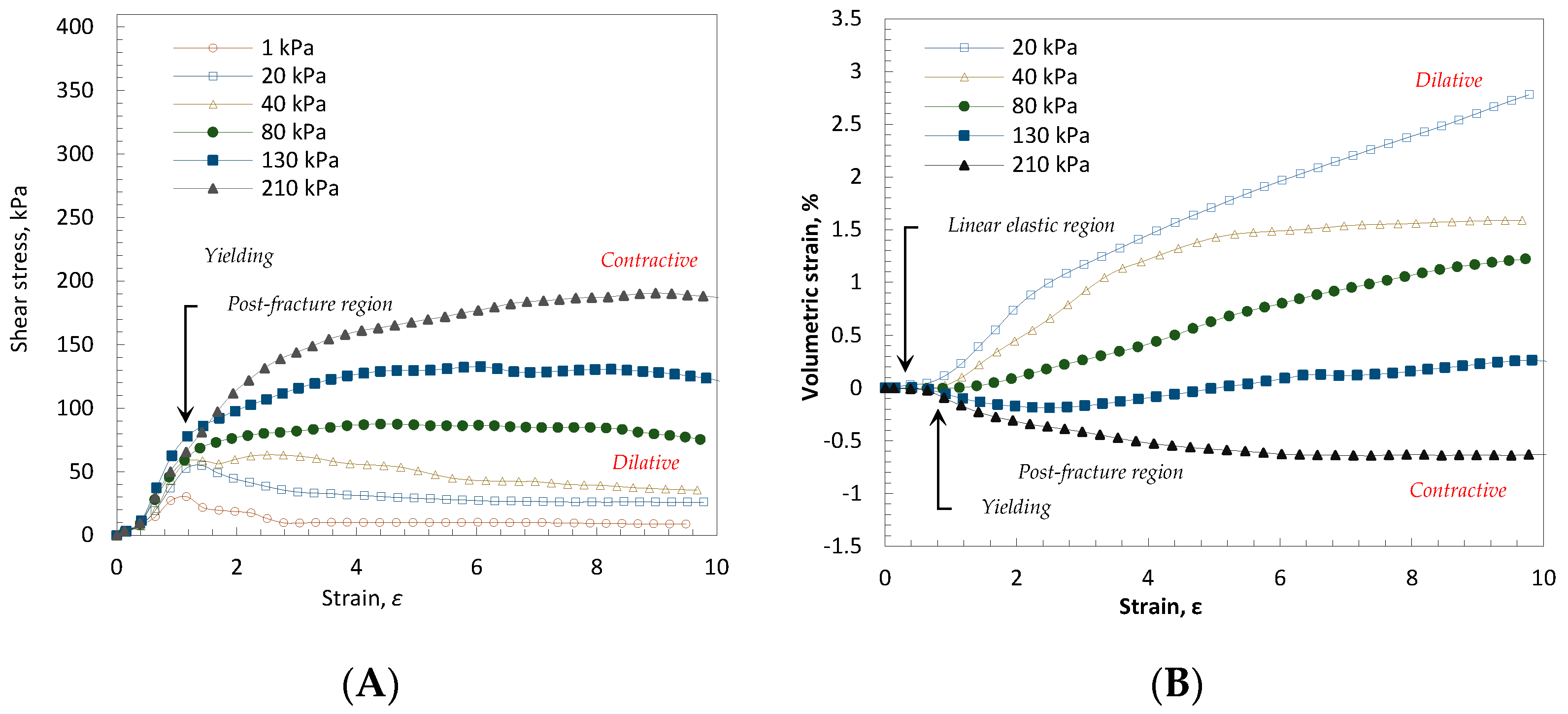
The yield characteristics of CPB are analyzed with dilation, stress–strain and strength properties. Figure 4 shows the stress–strain and dilative properties of 4.2% CPB at the 7-day curing interval. The stress–strain behavior is characterized by three phases, as shown in Figure 4A: an initial linear elastic response; the elastic phase, followed by yield, leading to the post-fracture response; and the post-fracture behavior characterized by the strain hardening or strain softening behavior depending on the normal stress and cohesion. The stress–strain behavior corresponds to the dilation–strain curves, as shown in Figure 4B. The curves are characterized by an initial stationary phase prior to fracture, followed by either contraction or dilation. Contractive behavior is associated with strain hardening, while dilation is associated with strain softening [22,23].
The post-fracture behavior of the CPB is governed by the ratio of the normal stress and cohesion. At the 3-day curing time with 4.2% binder content, the contraction occurs under the confining pressure of 130 and 210 kPa; while, in the samples with 6.9% binder content, the contraction occurs only at 210 kPa; by contrast, at 9.7% binder content, the specimens do not exhibit contraction. The result shows that the properties of CPB are controlled by cohesion. Indeed, the strength of CPB increases with cement content and curing time. The trends are illustrated with the peak strength characteristics, stiffness and dilation behavior.
Figure 4 shows that the strain softening and strain hardening effect corresponds to dilation and contraction. It can be seen that dilation corresponds to a decrease in shear strength, while contractive behavior corresponds to an increase in strength. At a low confining stress (20, 40, 80 kPa) with 4.2% CPB at 7 days, the increase in strain results in vertical dilation, which is similar to the over-consolidated soils due to the remolding of particles to a less dense state [22,23,24]. The increase in confining stress reduces the dilation effect. The dilative behavior shifts to contractile behavior at 2.5 times of the cohesion. The increase in strain results in vertical contraction, which could be explained by the remolding of particles to a more dense state [22,23]. The strength increase could be attributed to the transition from cohesion-based resistance to pure frictional resistance. The behavior of the CPB is similar to normally consolidated soil. The increase in confining stress led to the reconstitution of the soil particles to a more dense state [23,24].
The observed trend of cohesion is consistent with the crushing strength at 2.5 times reported by Mitchel et al., 1982, the reason for which is that the relatively high applied normal stresses degraded the test samples and altered their dilation, leading to a more compact state [1]. By contrast, under a lower applied normal stress, the specimen begins to expand, leading to less dense state in both the 6.9% and 9.7% CPB specimens with over 3 days of curing time. The result is similar to the artificial over-consolidation observed in cemented soils by Quiroga et al. (2017) in which the behavior can be idealized to normal and over-consolidated soils [25].
The stress–strain behavior is illustrated in Figure 5. At the stress level below 2.5 times of cohesion, the specimens exhibit a strain softening behavior, whereas at the stress level above 2.5 times of cohesion, the specimens exhibit a strain hardening behavior, as shown in Figure 5A. The change in strength corresponds to the change in volume and void, respectively, as shown in Figure 5B,C. The decrease in shear strength corresponds to the increase in volume and void space, which is consistent with the studies on soil behavior due to particles moving to a less dense state [22,23].
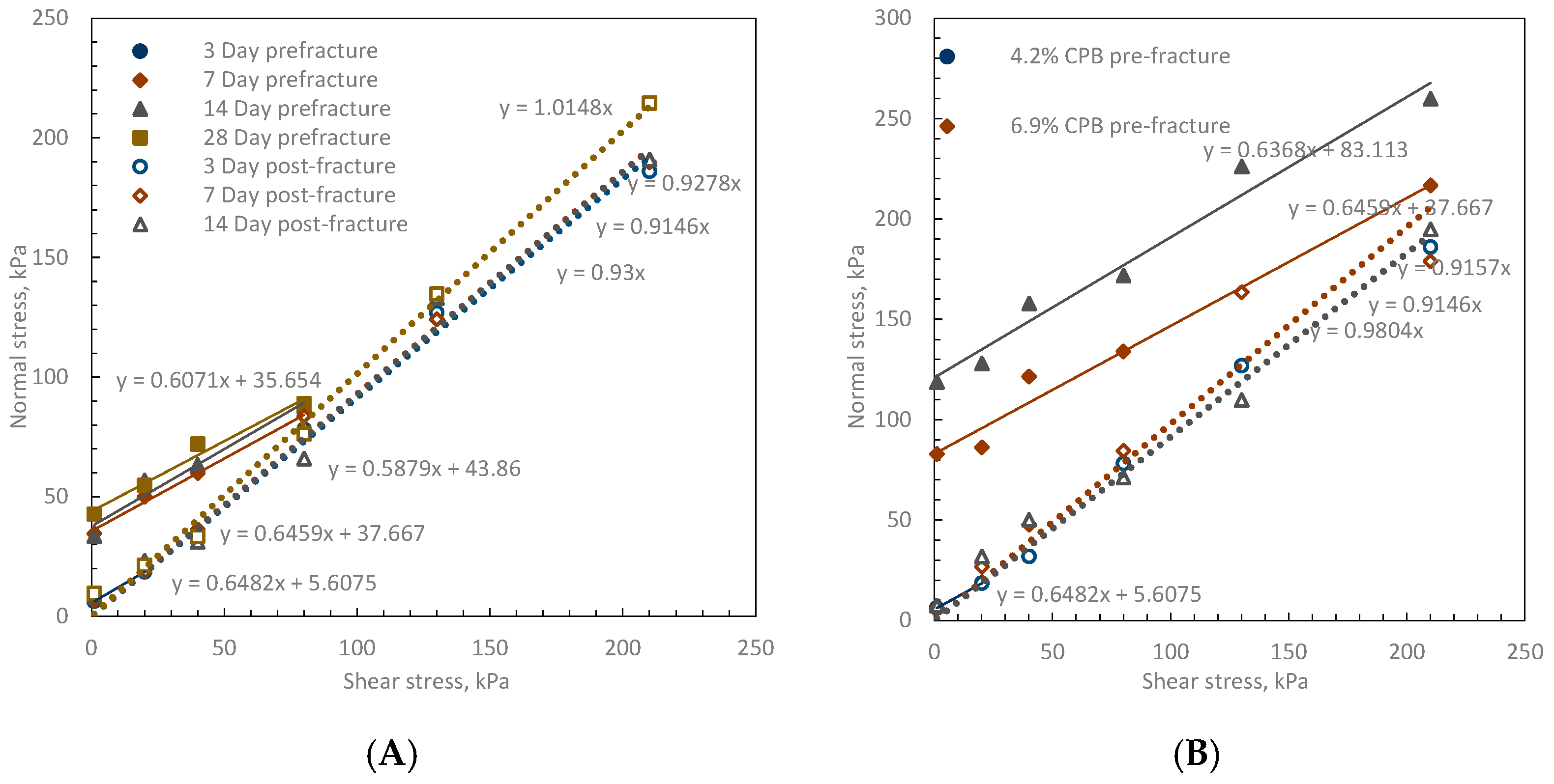
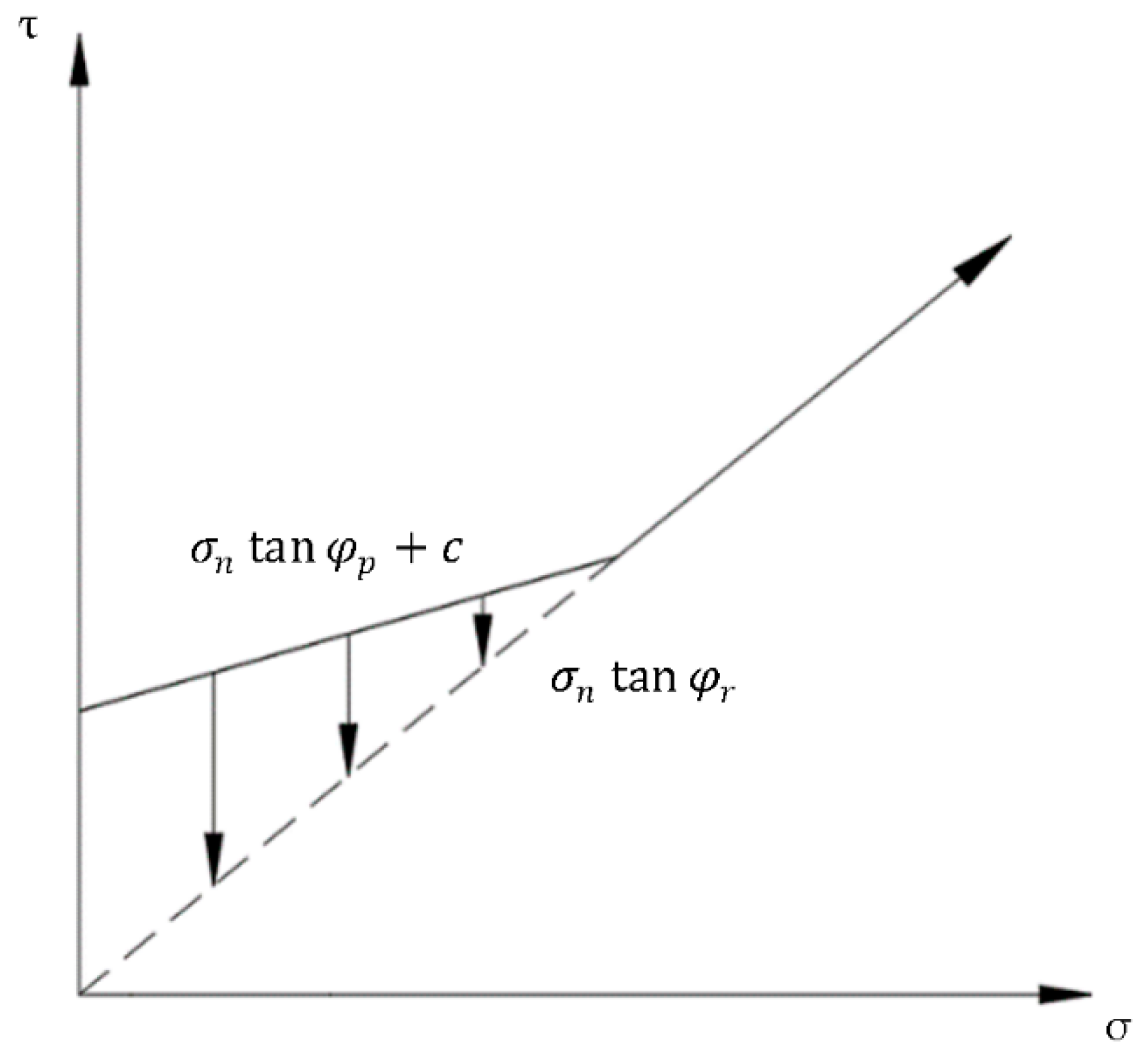
It can be seen that, regardless of the cement content and curing time, the strength properties are characterized by two envelopes, in which the pre-fracture behavior is governed by cohesion and peak frictional resistance, while the post-fracture behavior is governed by residual frictional resistance, as shown in Figure 6. The pre-fracture strength is
τ p = σ n tan φ p + c
where τ p is the shear strength; σ n is the confining stress; φ p is the peak angle of frictional resistance; and c is the cohesion.
The post-fracture strength is represented by
τ r = σ n tan φ r
where τ r is the shear strength; σ n is the confining stress; φ r is the residual angle of frictional resistance. The peak strength shifts from cohesion to frictional resistance as the normal stress increases. The peak and residual angle of resistance remain relatively consistent in all three cement contents and four curing times.
For the specific tailing stream, we analyzed the peak shear resistance transferred from cohesion and frictional resistance to pure frictional resistance at 2.5 times of cohesion, as illustrated in Figure 7. The peak strength mobilized by the frictional resistance could be greater than cohesion-based resistance. By analyzing the strength property of CPB, mine operations may significantly reduce the cement content and optimize their backfill design. Several operations have already implemented rigorous quality assurance methods, which enable them to use CPB with cement content of less than 0.5% in the backfill design [3]. Our result suggests that CPB should be analyzed with critical state soil mechanics at high stress levels rather than with Mohr–Coulomb parameters alone.

4. Conclusions

We analyzed the yield criterion of CPB through shear strength, stress–strain and dilation properties with three cement contents, four curing times and six stress intervals. The results showed that under a lower confining stress, the peak strength is governed by cohesion and frictional resistance. Under high loads, the peak strength is controlled by the angle of frictional resistance. Our data showed that CPB follows a Mohr–Coulomb criterion up to particle remolding, at which point it transfers to frictional material. Our result suggests that CPB should be analyzed with critical state soil mechanics rather than with Mohr–Coulomb parameters alone.
It should be noted that the study was conducted for a specific mine tailing and binder type. The results obtained in this work should not be assumed for other tailings and binder combinations. However, this work provides a baseline for mine operators and researchers to quantify their materials and establish the appropriate failure envelope for CPB designs.

Supplementary Materials

The following supporting information can be downloaded at: https://www.mdpi.com/article/10.3390/civileng3040059/s1, Supplementary file contains the drawing exchange format (DXF) and stereolithography (STL) of the 60 × 60 × 50 mm direct shear mold. The file consists of the side enclosure and base enclosure; however, tapping the screw holes is required for assembly. We encourage mine operators and researchers to use our design. However, we provide no warranty for our design, and we are not liable for any misuse or errors in the files.

Author Contributions

Conceptualization, A.P. and M.G.; methodology, A.P.; software, A.P.; validation, A.P. and M.G.; formal analysis, A.P.; investigation, A.P.; resources, M.G.; data curation, A.P.; writing—original draft preparation, A.P.; writing—review and editing, A.P. and M.G.; visualization, A.P.; supervision, M.G.; project administration, A.P.; funding acquisition, M.G. All authors have read and agreed to the published version of the manuscript.

Funding

This study was funded in part by the National Science and Engineering Research Council (NSERC) of Canada, University of Toronto, and the industrial funding from the Barrick Corporation.

Institutional Review Board Statement

Not applicable.

Informed Consent Statement

Not applicable.

Data Availability Statement

All the results, data, models or codes that support the findings of this study are available from the corresponding author upon reasonable request.

Acknowledgments

The authors would like to acknowledge the William’s Operation for providing the tailings, binders and process water. We would also like to thank Xiaoyu Song from Portland State University, USA, for his technical support.

Conflicts of Interest

The authors declare no conflict of interest. The funders had no role in the design of the study; in the collection, analyses, or interpretation of data; in the writing of the manuscript, or in the decision to publish the results.

References

  1. Mitchell, R.J.; Olsen, R.S.; Smith, J.D. Model studies on cemented tailings used in mine backfill. Can. Geotech. J. 1982, 19, 14–28. [Google Scholar] [CrossRef]
  2. Hassani, F.; Archibald, J. Mine Backfill; Canadian Institute of Mining, Metallurgy and Petroleum: Montreal, QC, Canada, 1998. [Google Scholar]
  3. Paterson & Cooke Canada Inc. Mine Backfill Design & Operation Course; Patterson & Cooke: Sudbury, ON, Canada, 2019. [Google Scholar]
  4. Mitchell, R.J. Sill mat evaluation using centrifuge models. Min. Sci. Technol. 1991, 13, 301–313. [Google Scholar] [CrossRef]
  5. Grabinsky, M. In situ monitoring for ground truthing paste backfill designs. In Paste 2010: Proceedings of the Thirteenth International Seminar on Paste and Thickened Tailings; Jewell, R., Fourie, A.B., Eds.; Australian Centre for Geomechanics: Perth, Australia, 2010; pp. 85–98. [Google Scholar] [CrossRef] [Green Version]
  6. Pakalnis, R.; Caceres, C.; Clapp, K.; Morin, M.; Brady, T.; Williams, T.; Blake, W.; MacLaughlin, M. Design Spans—Underhand Cut and Fill Mining. In Proceedings of the 107th Canadian Institute of Mining Annual General Meeting, Toronto, ON, Canada, 1–9 April 2005. [Google Scholar]
  7. De Souza, E.; Archibald, J.F.; Dirige, A.P. Underground Backfill Practices in Canadian Mines. In Proceedings of the 6th North America Rock Mechanics Symposium (NARMS), Houston, TX, USA, 5–9 June 2004. [Google Scholar]
  8. Keita, A.M.T.; Jahanbakhshzadeh, A.; Li, L. Numerical analysis of the failure mechanisms of sill mats made of cemented backfill. Int. J. Geotech. Eng. 2021, 16, 802–814. [Google Scholar] [CrossRef]
  9. Grabinsky, M.; Jafari, M.; Pan, A. Cemented Paste Backfill (CPB) Material Properties for Undercut Analysis. Mining 2022, 2, 7. [Google Scholar] [CrossRef]
  10. le Roux, K.; Bawden, W.F.; Grabinsky, M. Field properties of cemented paste backfill at the Golden Giant mine. Min. Technol. 2005, 114, 65–80. [Google Scholar] [CrossRef]
  11. Koupouli, N.J.; Belem, T.; Rivard, P.; Effenguet, H. Direct shear tests on cemented paste backfill–rock wall and cemented paste backfill–backfill interfaces. JRMGE 2016, 8, 472–479. [Google Scholar] [CrossRef] [Green Version]
  12. Fall, M.; Belem, T.; Samb, S.; Benzaazoua, M. Experimental characterization of the stress–strain behaviour. J. Mater. Sci. 2007, 42, 3914–3922. [Google Scholar] [CrossRef]
  13. Grabinsky, M.; Pan, A. Cemented paste backfill failure envelope at low confining stress. In Proceedings of the 13th International Symposium on Mining with Backfill, Katowice, Poland, 25–27 May 2021. [Google Scholar]
  14. Pan, A.; Grabinsky, M. Tensile Strength of Cemented Paste Backfill. Geotech. Test. J. 2021, 44, 1886–1897. [Google Scholar] [CrossRef]
  15. Pan, A.; Grabinsky, M.; Guo, L. Shear Properties of Cemented Paste Backfill under Low Confining Stress. Adv. Civ. Eng. 2021, 2021, 7561977. [Google Scholar] [CrossRef]
  16. Nasir, O.; Fall, M. Shear behaviour of cemented pastefill-rock interfaces. Eng. Geol. 2008, 101, 146–153. [Google Scholar] [CrossRef]
  17. Veenstra, R.L. A Design Procedure for Determining the In Situ Stresses of Early Age Cemented Paste Backfill. Ph.D. Thesis, University of Toronto, Toronto, ON, Canada, 2013. Available online: tspace.library.utoronto.ca/bitstream/1807/36027/1/Veenstra_Ryan_L_201306_PhD_thesis.pdf (accessed on 10 October 2022).
  18. Grabinsky, M.; Bawden, W.; Simon, D.; Thompson, R.; Veenstra, R. In Situ Properties of Cemented Paste Backfill from Three Mines. In Proceedings of the 66th Canadian Geotechnical Conference, Montreal, QC, Canada, 29 September–3 October 2013. [Google Scholar]
  19. Roscoe Postle Associates. Technical Report on the Hemlo Mine; Barrick Gold Corporation: Marathon, ON, Canada, 2017. [Google Scholar]
  20. Jafari, M. Experimental Study of Physical and Mechanical Properties of a Cemented Mine Tailings. Ph.D. Thesis, University of Toronto, Toronto, ON, Canada, 2020. Available online: tspace.library.utoronto.ca/handle/1807/101293 (accessed on 10 October 2022).
  21. ASTM D3080-04; Standard Test Method for Direct Shear Test of Soils Under Consolidated Drained Conditions. ASTM Standard; ASTM International: West Conshohocken, PA, USA, 2020.
  22. Casagrande, A. Characteristics of Cohesionless Soils Affecting the Stability of Slopes and Earth Fills. J. Boston Soc. Civ. Eng. 1936, 23, 13–32. [Google Scholar]
  23. Knappett, J.A.; Graig, R.F. Graig’s Soil Mechanics, 8th ed.; Taylor & Francis: New York, NY, USA, 2012. [Google Scholar]
  24. Roscoe, K.H.; Schofield, A.N.; Wroth, C.P. On the Yielding of Soils. Géotechnique 1958, 8, 22–53. [Google Scholar] [CrossRef]
  25. Quiroga, A.J.; Thompson, Z.M.; Muraleetharan, K.K.; Miller, G.A.; Cerato, A.B. Stress–strain behavior of cement-improved clays: Testing and modeling. Acta Geotech. 2017, 12, 1003–1020. [Google Scholar] [CrossRef]
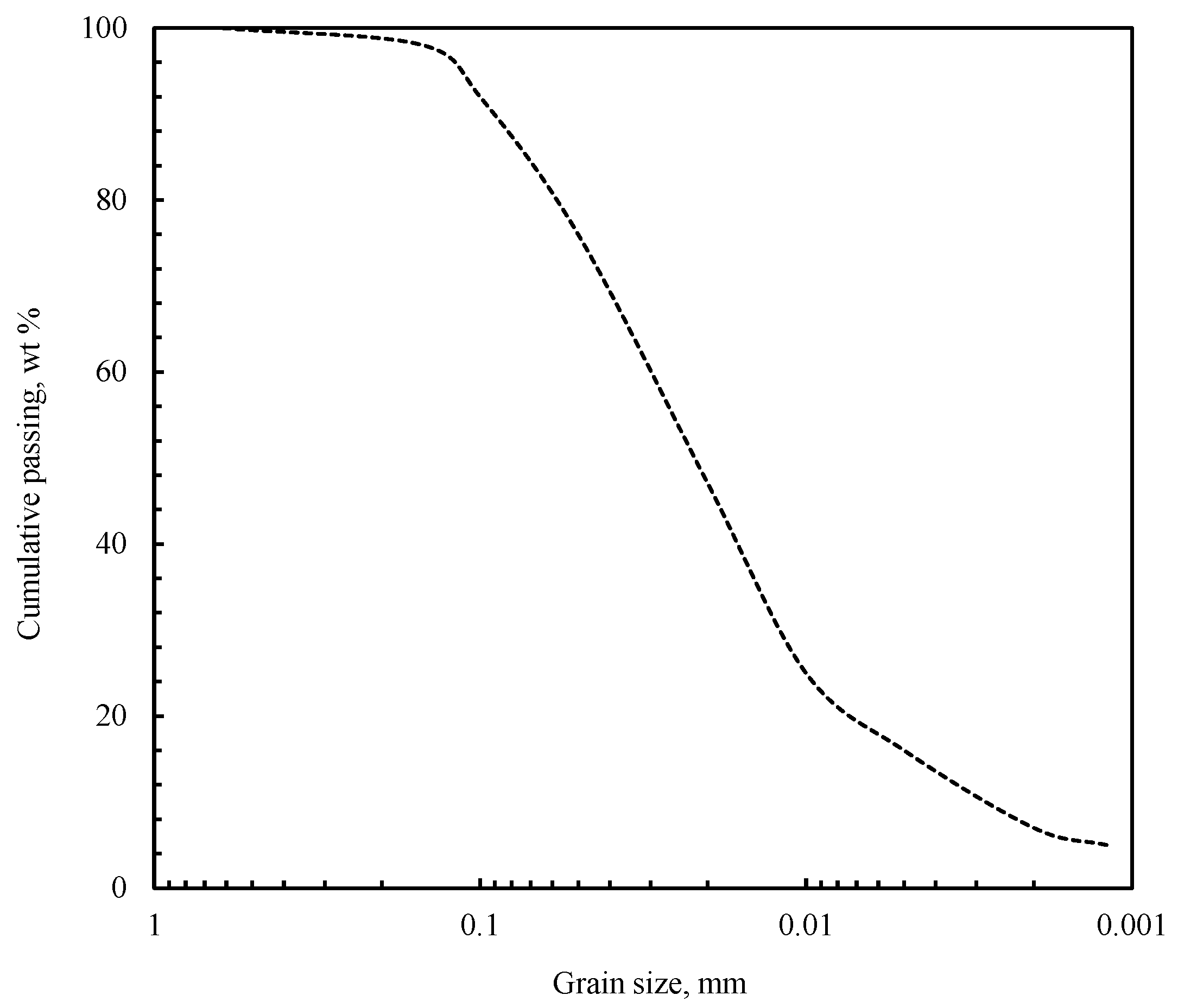
Figure 1. Particle size distributions of mill tailings.
Civileng 03 00059 g001
Figure 2. Direct shear instrument setup. (A) System schematic. (B) System photograph.
Civileng 03 00059 g002
Figure 3. Schematic of 4-part split mold. (A) Mold schematic. (B) Mold photograph.
Civileng 03 00059 g003
Figure 4. Stress–strain and dilation of 4.2% CPB at the 7-day curing interval. (A) Stress–strain behavior. (B) Volume change with strain.
Civileng 03 00059 g004
Figure 5. Stress–strain and dilation of CPB. (A) Stress–strain. (B) Volumetric strain. (C) Void ratio strain.
Civileng 03 00059 g005
Figure 6. Strength envelope of CPB. (A) Strength envelope with curing time 4.2% CPB. (B) Strength envelope with cement content at day 3.
Civileng 03 00059 g006
Figure 7. Strength properties of CPB.
Civileng 03 00059 g007
Table 1. Mill tailings and binder chemical compositions.
Chemical compositionCaOSiO2SO3Al2O3MgOFe2O3K2ONa2O
Mill tailings (wt.%)64.220.04.13.93.13.00.50.2
Chemical compositionSiO2Al2O3CaOMgOK2ONa2OFe2O3STiO2P2O5Ba
Binder (wt.%)59.812.23.63.53.43.22.40.60.40.20.1
Table 2. Test configurations.
Binder Content, (wt.%)Curing Time, DaysStress Intervals, kPaNumber of Samples
4.23, 7, 14, 281, 20, 40, 80, 130, 21024
6.93, 7, 14, 281, 20, 40, 80, 130, 21024
9.73, 7, 14, 281, 20, 40, 80, 130, 21024
Publisher’s Note: MDPI stays neutral with regard to jurisdictional claims in published maps and institutional affiliations.