Abstract
Existing literature suggests that substituting mineral aggregates with tire-derived aggregate (TDA) in concrete increases the ductility and toughness of the concrete at the cost of lowering its strength and stiffness. Hence, TDA concrete has applications in dynamic systems, such as lateral resisting frames sustaining seismic loads. This study investigated the application of TDA concrete in buckling-restrained braced frames (BRBFs). Buckling-restrained brace (BRB) specimens included steel plates encased with concrete mixtures containing TDA coarse aggregates compared to conventional concrete. Testing involved shake-table testing of a single-span, one-story, steel-braced frame with single-leg conventional or TDA concrete BRBs under harmonic, periodic, impulse, and ground motion loadings. Results included time-history responses and backbone curves of the BRBF specimens. Analytical interpretation of results included determining effective mass, stiffness, damping ratio, toughness, and ductility of BRBFs for TDA versus conventional concrete.
1. Introduction
Moment-resisting and braced frames are typical lateral force-resisting systems in buildings [1]. Moment-resisting mechanisms dissipate energy by undergoing large lateral displacements within the plastic region [2]. The demand for large displacement in ordinary connections results in the fracture of beam–column connections. Further, large drifts damage non-structural elements. Hence, moment-resisting frames require special attention in their design to mitigate large lateral displacements; thus, there are practical and economic constraints associated with these systems. In contrast, concentrically braced frames (CBFs) address the drift issue and reduce the impact on non-structural elements [3]. However, there have been concerns about the performance of CBFs in past earthquakes [4], such as 1985 Mexico [5], 1989 Loma Prieta [6], 1994 Northridge [7], and 1995 Hyogo-ken Nanbu [8]. Unsymmetrical behavior in tension and compression is one of the main reasons for the poor performance of CBFs in past earthquakes. Under lateral loading, steel braces yield in tension and provide a plastic ductile deformation with a good source of energy dissipation. However, the buckling of braces in compression provides a poor source of energy dissipation. The revision of CBFs to eccentrically braced frames (EBFs) has undoubtedly enhanced the system’s behavior (at an increased cost), but it has not addressed the buckling problem.
Buckling-restrained braced frames (BRBFs) endeavor to mitigate the challenge of unsymmetrical behavior in tension and compression [9,10,11] through enhanced ductility and stiffness [12,13]. Thus, these systems are popular in seismic-prone regions for their excellent energy dissipation capacity [4,14]. Proposed mechanisms may involve enclosing a ductile metal like steel in either concrete or a mortar-filled steel tube to restrain buckling of the core plate. The steel plate carries the entire axial load and concentrates plastic deformation and energy dissipation. A typical steel core has a flat or cruciform shape and usually a smaller cross-sectional area. The plate length is divided into three zones: yielding, transition, and connecting (Figure 1). The outer casing and restraining material provide lateral support and prevent global buckling. A small gap is made between the steel core and the restraining material to ensure no axial force is transmitted to the outer casing and to allow the steel core to elongate and contract easily. Because of the un-bonding/decoupling of the core, the confining material is not subjected to high axial stress, thus allowing the steel core plate to undergo elastoplastic buckling. BRBs achieve balanced hysteretic behavior by yielding in compression just as in tension yielding. The strength of the compressive yielding of a BRB is typically 10% higher than its tensile strength. This difference is due to both the accumulation of compressive stresses in the restraining material and to the Poisson effect, which causes the steel core area yielding under the compression to be larger than the area under the tension [15].
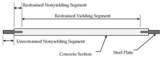
Figure 1.
Schematic of a buckling-restrained brace (after Sabelli 2004 [15]).
Buckling-restrained braces achieve substantial ductility and balanced hysteretic behavior by undergoing plastic yielding in tension and compression, which accommodates compression yielding before the onset of buckling [16]. Thus, they exhibit high-energy dissipation [17]. Previous research has also shown that a steel frame with BRBs had a damping ratio greater than 6%; however, conventional steel braces exhibit damping ratios below 0.4% [18]. Thus, BRBs have the added advantage of increasing the damping levels of a steel structure due to the higher viscous damping of materials. This effect adds to the damping offered by the hysteretic behavior of the system.
According to the BRBF qualification testing protocol [19], the recommended elastic ductility demand value for concrete-infilled BRB is 7.5. With careful design, the mean ductility of BRBs can range between 20 to 25, which is greater than the code-recommended value of 7.5 [20]. Such a range in ductility demand can be achieved by adjusting various restraining mechanisms [21]. Furthermore, design optimization depends on the overstrength, ductility, and response modification factors of BRBFs, as well as building structure characteristics like height [22].
In the hope of reducing health hazards caused by scrap tires, researchers have turned their interest to utilizing such tires in the production of soil embankments [23,24], asphalt concrete [25], and cementitious concrete [26,27,28]. These materials, known as tire-derived aggregates, provide energy dissipation and damping in various applications [26]. Concrete produced from such recycled tires is known as tire-derived aggregate concrete (TDA) or rubberized concrete. Replacing some aggregates with recycled tire wastes (Figure 2) can alter the mechanical properties of materials, including reducing strength and rigidity and increasing toughness and ductility [29]. These changes are proportional to the volumetric contents of TDA. The minimum rate of substituting coarse aggregates with TDA to achieve significant toughness is 60% for normal-weight aggregates [26] and 80% for lightweight aggregates [29]. The higher percentage for lightweight aggregates can be attributed to the higher damping and energy dissipation of these aggregates, which in turn are due to their porosity and micromechanical characteristics [29]. Fracture mechanic analysis of TDA concrete confirmed experimental observations of its enhanced toughness due to the bridging action of TDAs in cementitious aggregates [30]. Furthermore, experimental dynamic studies revealed that tire-derived aggregates increased the damping ratio of concrete specimens subject to impact loading [31]. These enhancements contribute to the sustainability and resilience of concrete elements subjected to the dynamic effects of natural disasters like earthquakes or artificial incidents like vehicular collisions [32].
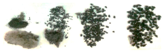
Figure 2.
Crumb rubber manufactured via the mechanical shredding of recycled tires.
Fiber-reinforced polymer was introduced to BRBs to avoid corrosion [33]. This application was later investigated by Dusicka and Tinker (2013); by using an aluminum core and glass fiber-reinforced polymer case, they reduced global buckling by 27% compared with a traditional BRB [34]. Deng and Pan [35] proposed a new glass fiber-reinforced polymer steel BRB. In their method, four GFRP tubes strengthen the steel core, and local buckling occurs at the end of the steel core and GFRP case. The conventional BRB tube is replaced by GFRP, which prevents local buckling of the steel core. However, this method weakens global buckling due to low longitudinal stiffness [13].
The effects of concrete properties on BRBFs are often neglected due to the low tensile strength and damping of concrete, as well as the lack of mechanisms to transfer compressive loads to encasing concrete materials [36]. However, applying concrete material with higher damping properties may change perceptions of the contribution of concrete to the performance of the BRBF system. Prior research has shown that TDA can be used in structures where energy absorption is a primary concern. Hence, in this study, a novel material of tire-derived aggregate concrete (TDA) was used as a restraining material to study the dynamic properties of BRBs [29]. The ductility, energy dissipation capacity, damping ratios, and failure pattern of BRB with TDA concrete and conventional concrete were investigated and compared.
2. Experimental Procedure
2.1. Shake Table
The Structures Laboratory of CSU Fresno conducted a large-scale testing program to study the dynamic behavior of BRBFs using a shake table. The shake table is driven horizontally by 100 HP electric motors capable of delivering hydraulic fluid at 100 GPM and 20.7 MPa (3000 psi.). All of the hydraulic actuators are located in the chamber beneath the shake table. The size of the shake table is 2.44 m by 2.06 m (8 ft × 6.75 ft). A 178 kN (40 kips) structure can move +/−12.7 cm (+/− 5 in.) at 1.5 g with a frequency of 2.2 Hz. The testing prototype was a one-story system with three parallel frames, including two simple external frames and one internal single-leg braced frame. The brace samples included three un-bonded conventional concrete BRBs and three un-bonded TDA concrete BRBs; each BRB sample had a steel core plate encased in a concrete section.
2.2. Specimens
The strength and stiffness of BRBs under compression can be adjusted by altering their geometric properties, such as cross-sectional area, effective length, and strength of the confining element. The steel core plate was designed to resist a lateral load of 27.7 kN (6.24 kips). The required member to resist the lateral load is an A36 grade 5.84 cm × 0.32 cm (2.3 in. × 1/8 in.) steel plate with 1.86 cm2 (0.288 in2) cross-sectional area. The objective of the dynamic test was to allow the core plate to buckle under applied lateral loads and observe the damping effect on the system’s behavior. Adding an outer sleeve would have increased the brace’s compression load beyond the shake table’s capacity to cause buckling; hence, the sample was cast without an outer sleeve. The buckling loads of the BRBs were estimated with Equation (1), and the results are presented in Table 1.

Table 1.
Target design loads before testing concrete cylinders.
In this equation, ) is the effective length of the specimen; and are the effective modulus of elasticity and moment of inertia of the steel core plate, respectively; and and are the effective modulus of elasticity and moment of inertia of the concrete, respectively.
Using the Euler buckling load equation, the target concrete strength assumed in the buckling load calculation was 20.7 MPa (3000 psi). The outside cross-sectional area of a BRB after the buckling load calculation (Figure 3) was 8.64 cm × 11.68 cm (3.4 in. × 4.6 in.).
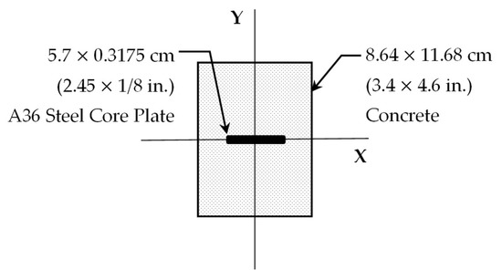
Figure 3.
Cross-section of BRB.
The total length of the brace was 2.51 m (99 in.), and the effective pin-pin length of the brace was 2.31 m (91 in.) (Figure 4). The effective length was used to calculate the buckling load of the frame, with the expected buckling loads given in Table 1.
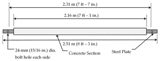
Figure 4.
Longitudinal section of BRB.
In concrete, TDA with 0.95 cm (3/8 in.) nominal size replaced mineral gravel of the same size (Table 2) for a target strength of 35 MPa (5000 psi). Other adjustments were necessary to preserve the integrity and workability of ordinary and TDA concrete. Both the framework and casting of BRBs are presented in Figure 5.
Table 2.
Concrete mix design per 28 L (cubic feet).
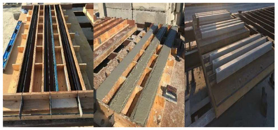
Figure 5.
The casting of BRB infill with TDA concrete and conventional concrete.
2.3. Material Testing
Six plastic single-use 0.10 m × 0.20 m (4 in. × 8 in.) cylindrical molds were used for the TDA and conventional concrete tests (Figure 6). Compression testing was carried out using a 500 kN (120 kips) Tinius Olsen manually operated universal testing machine. Cylinders were placed in the universal testing machine using rubber caps at the top and bottom, and the compression load was applied at a rate of 0.24 MPa (35 psi) per second.
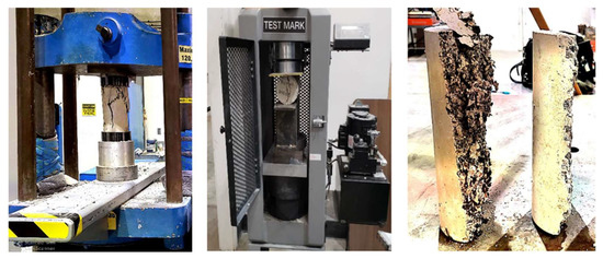
Figure 6.
Compression test (left), splitting tensile test (middle), and broken splitting tensile samples of TDA and conventional concrete (right).
The splitting tensile specimen was tested on the same day. The sample was placed between steel bars, and the load was applied at 48.9 KN (11 kips) per second.
2.4. Testing Steel Frame
Figure 7 shows the testing frame plan and elevation [36,37]. The longitudinal and transverse directions of the building were defined as the X and Y directions, respectively. The structural configuration consisted of two 0.762 m (2.5 ft) bays, each in the Y direction, and one bay of 1.83 m (6 ft) in the X direction. The story height was 2.44 m (8 ft). The scaling of the frame followed the limitation of the shake table dimensions and reached the height of a 3 m (10 ft) one-story building, including concrete slabs representing floors. The frame comprised six grade 50 W6 × 9 columns and seven grade 50 W6 × 15 beams. The frame was designed to carry two 8.9 cm (3.5 in.)-thick concrete slabs weighing 9.8 kN (2.2 kips) each. The frame was braced against lateral translation in the weak direction with safety tension slings with a capacity of 4.4 kN (1 kip) each, shown as yellow wires in Figure 7.
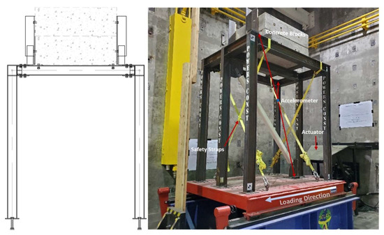
Figure 7.
Existing frame 3D elevation (1 in. = 2.54 cm).
The beams connected the columns using 19 mm (3/4 in.) diameter high-strength bolts. The frame was connected to the shake table using 28.6 mm (9/8 in.) diameter high-strength bolts and 9.5 mm (3/8 in.) grade 50 base plates (Figure 7). The brace was connected to the top with a 12.7 mm (1/2 in.)-thick grade 36 gusset plate through a 19 mm (3/4 in.) diameter high-strength bolt (Figure 8). The top gusset plate was welded to the web plate of the beam with an 8 mm (5/16 in.) weld (Figure 8). The bottom of the brace was connected to a 15.9 mm (5/8 in.) grade 36 knife plate. The connections were designed to withstand the transferred load by the expected capacity of the brace, and the welds connected the knife plate to the column flange using the total allowable force of 89 kN (20 kips) for vertical shear and tensile loading.
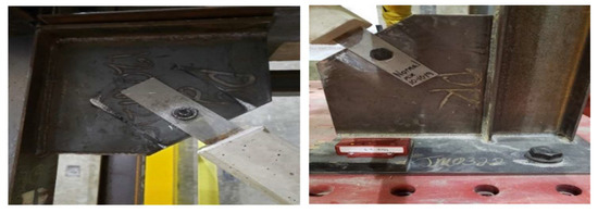
Figure 8.
Bolted connections at the top (left image) and bottom (right image) of the brace.
2.5. Instrumentation
Accelerometers sensed and recorded the vibrating motions of the shake table and the prototype. Two accelerometers were placed on opposite sides at the top of the frame, in addition to one at the base of the frame sensing the actual shake table motion (Figure 9).
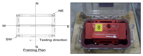
Figure 9.
Accelerometer and placing of accelerometers.
2.6. Base Excitations
Base excitations comprised selected modified nearfield ground acceleration records (Table 3), including records from the El Centro, Loma Prieta, Tabas, Gazli, and Dutzce earthquakes that were obtained from the Pacific Earthquake Engineering Research (PEER) Ground Motion Database [38]. Due to the to 12.7 cm (5 in.) displacement constraint of the shake table, the scaling of ground motions was necessary to limit the base displacements. The time scale was proportional to the square root of the displacement scale to keep the maximum acceleration the same as that of the original record. In addition, prototypes were subjected to 1 cm (0.4 in.) amplitude with 2 Hz frequency increasing amplitude FEMA loading, 0.5 cm (0.2 in.) increasing frequency sweep loading, and scaled earthquake loadings. Table 4 lists the designation and content of the shake table test runs. Figure 10 shows the displacement time history of sample records.
Table 3.
Testing matrix.
Table 4.
Shake table loading data.
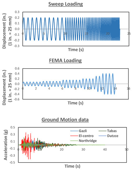
Figure 10.
Loading history.
3. Results and Discussions
3.1. Concrete Material Properties
In the current study, the recorded compression strength of conventional concrete was 34.6 MPa (5022 psi), beyond the assumed strength of 20.7 MPa (3000 psi). In contrast, the recorded strength of TDA concrete was 10.6 MPa (1534 psi), below the expected strength of 20.7 MPa (3000 ksi). The strength of TDA concrete likely decreased due to the addition of crumb rubber pieces. The recorded tensile strength was 11.2 kN (2.5 kips) and 0.36 kN (0.08 kips) for conventional and TDA concrete, respectively. These values adjusted target loads for realistic analyses of prototypes.
Initially, the brace was designed per Table 1. After calculating the actual strength of the concrete, the buckling loads were calculated using experimental results (Table 5).
Table 5.
Observed loads after cylinder testing.
3.2. Time History Responses
Recorded time histories were adjusted for the incidental misalignment of accelerometers and baseline corrections [39]. Figure 11 shows sample corrected time-history plots for FEMA loadings.
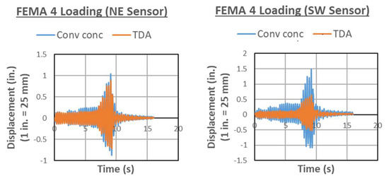
Figure 11.
Time history of NE and SW sensors for FEMA 4 loading.
Recorded displacement time histories were compared with theoretical linear elastic displacements. Duhamel’s integral was used to calculate the theoretical linear elastic displacements for scaled earthquake responses [40]. The maximum linear elastic displacement for sweep loading was calculated using the classic solution to sinusoidal loadings. The same equation was used for FEMA loading with constant frequency and an amplitude that increased from 0.19 cm (0.075 in.) to 1.02 cm (0.4 in.). Table 6 gives the detailed displacement-response history of TDA and conventional concrete. The reported time histories used in the analyses were the average values of NE and SW sensors.
Table 6.
Recorded displacements.
The slight difference between the recorded time histories of NE and SE sensors indicates a negligible incidental rotation of the frame (Table 7).
Table 7.
Rotation of the frame.
3.3. Design Parameters
The frequency, fundamental period, modulus of elasticity, and effective stiffness of braced frames were calculated from the impulse loading with 2.54 cm (1 in.) base movement, as shown in Table 8. The modulus of elasticity was calculated using procedures by [1]. The damping ratio (Table 9) was calculated from free vibrations of FEMA4 and impulse loadings using the logarithmic decrement equation obtained from the deformation response curves [40]. These specific loadings resulted in a linear response of the structure. It was observed that the damping ratio of the brace was higher in compression than in tension. Under tension, the core plate behaved elastically and thus dissipated less energy, while under compression, the brace became elastoplastic and thus dissipated more energy.
Table 8.
Properties of the frame.
Table 9.
The damping ratio of the braced frame.
Like the selected samples in Figure 11, the cyclic loading time histories determined the hysteretic curves for TDA and conventional concrete (Figure 12). These curves were the basis for calculating ductility and toughness (Table 10). Since by design the braces did not accommodate compression yielding before the onset of buckling, the determined ductility ratios for both braces were less than the code-recommended value of 7.5. Hence, concrete in both braces resisted a buckling load equal to the tension load of the steel plate, and braces yielded non-linearly in the elastoplastic zone (Figure 12). The interpretation of results relies on the observation that a buckling of steel controlled the failure, not a tensile yielding of steel or a compressive failure of concrete. In practice, applying an outer casing would provide a balanced hysteresis curve. However, the aim of this experiment was to observe the contributions of concrete during buckling; thus, allowing the brace to buckle was instrumental to the experiment. The responses of the prototypes indicated that the TDA concrete brace had more significant damping but less ductility than conventional concrete. This result was likely due to the reduced strength of TDA concrete, which did not develop adequate flexural strength to delay the buckling of the core steel plate compared to conventional concrete.
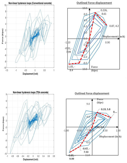
Figure 12.
Non-linear hysteresis loops for FEMA 4 loading (solid) and resulted backbone curve (dashed).
Table 10.
Ductility demand and toughness (linear elastic).
The backbone curve was one of the most important derivatives of the current test results. This curve is the basis for determining strength adjustment factors ω and ωβ, which specify the compressive and tensile capacities of BRBFs (Table 11). These values indicated that considering its tensile behavior, the TDA concrete brace was not advantageous. The curve is defined by brace normalized axial force versus displacement. Figure 13 shows the schematic view of the backbone curve for conventional and TDA concrete braces.
Table 11.
Strength adjustment factors.
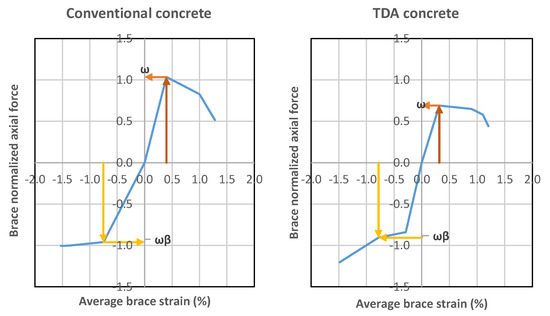
Figure 13.
Backbone curves for FEMA4 loading.
After calculating the damping of both the conventional and TDA concrete, the response spectrums were used to calculate the deformation response factor of each (Figure 14; Figure 15). The damping ratios used for the development of the response spectrums were average values from Table 9, summarized in Table 12. The application of average values relies on the assumption that the response to a given loading is balanced between tensile and compressive effects.
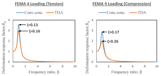
Figure 14.
Deformation response factor versus frequency ratio.
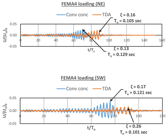
Figure 15.
Deformation response factor vs. time ratio.
Table 12.
Average Damping ratios.
A brace with outer sleeves and a decoupled core provides greater compressive strength than tensile strength; the strength difference is usually less than 10% [15,41]. Because of the Poisson effect, the total area under compression is larger than the area under tension [42], and it is impossible to eliminate all the stress in the brace under compression [41]. In conventional concrete, the maximum tension force in the brace at failure was 7.29% more than the compression force; in TDA concrete, the maximum tension force at failure was 3.32% more than the compression force (Figure 16).
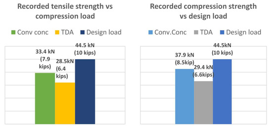
Figure 16.
Buckling load vs. applied force.
3.4. Debonding and Failure
Initial setting cracks developed in concrete after 32 days of casting, and these cracks/bonding lengths were the basis for studying the failure pattern (Figure 17). Due to the Poisson effect, the initial setting crack propagates, and the concrete de-bonds from the plate. In this study, the failure of the brace (Figure 18) was an elastoplastic failure, mainly concentrated at the bottom of the plate by design, using a planted small eccentricity at the connection. This eccentricity ensured consistency of buckling failures at the steel plate for a reliable comparison between various specimens.
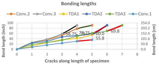
Figure 17.
Bonding length (highlighted ends are failure lengths).
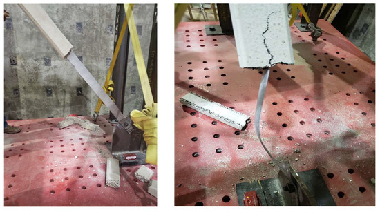
Figure 18.
Failure pattern.
4. Conclusions
Experimental tests were conducted on a 2.44 m × 1.83 m (8 ft × 6 ft) frame equipped with three TDA concrete-infilled BRBs and three conventional braces working within their elastoplastic range. TDA BRB test results were compared with those of conventional braces. The following conclusions are offered:
- Compared to a conventional concrete brace, a TDA concrete brace provides the additional benefit of increasing damping on the frames (ζ > 17% in tension and ζ > 34% in compression).
- Although TDA braces increased both the frame’s damping levels and fundamental period, they dissipated less energy than conventional braces due to a lack of ductility. Therefore, it can be concluded that TDA concrete braces may be a superior alternatives in a system where damping is of primary concern.
Author Contributions
Conceptualization, F.M.T.; methodology, F.M.T.; software, N.B.P.; validation, N.B.P., A.N. and O.F.; formal analysis, N.B.P.; investigation, N.B.P. and L.C.; resources, N.B.P. and L.C.; data curation, N.B.P., L.C. and A.N.; writing—original draft preparation, N.B.P.; writing—review and editing, A.N., F.M.T. and O.F.; visualization, N.B.P. and A.N.; supervision, F.M.T. and O.F.; project administration, F.M.T. All authors have read and agreed to the published version of the manuscript.
Funding
This research received no external funding.
Data Availability Statement
Not applicable.
Acknowledgments
Authors acknowledge MidState Precast Co. for casting buckling resisting braces and Powers Construction & Engineering Inc. for fabricating the steel prototype.
Conflicts of Interest
The authors declare no conflict of interest.
References
- Bruneau, M.; Uang, C.M.; Sabelli, R. Ductile Design of Steel Structures; McGraw-Hill Education: New York, NY, USA, 2011. [Google Scholar]
- Dehghani, A.; Fischer, G.; Nateghi Alahi, F. Strengthening masonry infill panels using engineered cementitious composites. Mat. Struct. 2015, 48, 185–204. [Google Scholar] [CrossRef]
- Chen, C.C.; Chen, S.Y.; Liaw, J.J. Application of low yield strength steel on controlled plastification ductile concentrically braced frames. Can. J. Civ. Eng. 2001, 28, 823–836. [Google Scholar] [CrossRef]
- Sabelli, R.; Mahin, S.; Chang, C. Seismic demands on steel braced frame buildings with buckling-restrained braces. Eng. Struct. 2003, 25, 655–666. [Google Scholar] [CrossRef]
- Scholl, R.E. Observations of the performance of buildings during the 1985 Mexico earthquake, and structural design implications. Int. J. Min. Geol. Eng. 1989, 7, 69–99. [Google Scholar] [CrossRef]
- Kim, H.I.; Goel, S.C. Upgrading of braced frames for potential local failures. J. Struct. Eng. 1996, 122, 470–475. [Google Scholar] [CrossRef]
- Goltz, J.D. The Northridge, California Earthquake of January 17, 1994: General Reconnaissance Report; Report No. NCEER-94-0005; National Centre for Earthquake Engineering Research: Buffalo, NY, USA, 1994. [Google Scholar]
- Nakashima, M.; Inoue, K.; Tada, M. Classification of damage to steel buildings observed in the 1995 Hyogoken-Nanbu earthquake. Eng. Struct. 1998, 20, 271–281. [Google Scholar] [CrossRef]
- López-Almansa, F.; Castro-Medina, J.C.; Oller, S. A numerical model of the structural behavior of buckling-restrained braces. Eng. Struct. 2012, 41, 108–117. [Google Scholar] [CrossRef]
- Hosseinzadeh, S.; Mohebi, B. Seismic evaluation of all-steel buckling restrained braces using finite element analysis. J. Const. Steel Res. 2016, 119, 76–84. [Google Scholar] [CrossRef]
- Pham, T.M.; Zhang, X.; Elchalakani, M.; Karrech, A.; Hao, H.; Ryan, A. Dynamic response of rubberized concrete columns with and without FRP confinement subjected to lateral impact. Const. Buil. Mat. 2018, 186, 207–218. [Google Scholar] [CrossRef]
- Black, C.; Aiken, I.D.; Makris, N. Component Testing, Stability Analysis, and Characterization of Buckling-Restrained Unbonded Braces (TM); PEER 2002/08; Pacific Earthquake Engineering Research Center, University of California: Berkeley, CA, USA, 2002. [Google Scholar]
- Sun, H.; Jia, M.; Zhang, S.; Wang, Y. Study of buckling-restrained braces with concrete infilled GFRP tubes. Thin-Walled Struct. 2019, 136, 16–33. [Google Scholar] [CrossRef]
- Flogeras, A.K.; Papagiannopoulos, G.A. On the Seismic Response of Steel Buckling-Restrained Braced Structures Including Soil-Structure Interaction. Earthq. Struct. 2017, 12, 469–478. [Google Scholar] [CrossRef]
- Sabelli, R.; López, W. Design of buckling-restrained braced frames. Mod. Steel Constr. 2004, 44, 67–74. [Google Scholar]
- Yu, Y.J.; Tsai, K.C.; Li, C.H.; Weng, Y.T.; Tsai, C.Y. Analytical simulations for shaking table tests of a full scale buckling restrained braced frame. Procedia Eng. 2011, 14, 2941–2948. [Google Scholar] [CrossRef]
- Kim, J.; Choi, H. Behavior and design of structures with buckling-restrained braces. Eng. Struct. 2004, 26, 693–706. [Google Scholar] [CrossRef]
- Guerrero, H.; Escobar, J.A.; Teran-Gilmore, A. Experimental damping on frame structures equipped with buckling-restrained braces (BRBs) working within their linear-elastic response. Soil Dyn. Earthq. Eng. 2018, 106, 196–203. [Google Scholar] [CrossRef]
- Sabelli, R. Recommended provisions for buckling-restrained braced frames. Eng. J. Am. Inst. Steel Const. 2004, 41, 155–176. [Google Scholar]
- Fahnestock, L.A.; Sause, R.; Ricles, J.M.; Lu, L.W. Ductility demands on buckling-restrained braced frames under earthquake loading. Earthq. Eng. Eng. Vib. 2003, 2, 255–268. [Google Scholar] [CrossRef]
- Tremblay, R.; Bolduc, P.; Neville, R.; DeVall, R. Seismic testing and performance of buckling-restrained bracing systems. Can. J. Civ. Eng. 2006, 33, 183–198. [Google Scholar] [CrossRef]
- Asgarian, B.; Shokrgozar, H.R. BRBF response modification factor. J. Constr. Steel Res. 2009, 65, 290–298. [Google Scholar] [CrossRef]
- Sadrinezhad, A.; Tehrani, F.M.; Jeevanlal, B. Shake Table Test of Railway Embankment Consisting of TDA and LECA. In Proceedings of the Geo-Congress 2019: Earthquake Engineering and Soil Dynamics, Philadelphia, PA, USA, 24–27 March 2019; pp. 31–39. [Google Scholar] [CrossRef]
- Tehrani, F.M.; Sadrinezhad, A.; Bajestani, M.S. Numerical simulation of the dynamic response of rail ballast with tire-derived aggregates. In Proceedings of the 11th US National Conference on Earthquake Engineering, Los Angeles, CA, USA, 25–29 June 2018; p. 1337. [Google Scholar]
- Tehrani, F.M. Noise abatement of rubberized hot mix asphalt: A brief review. Int. J. Pavement Res. Tech. 2015, 8, 58–61. [Google Scholar] [CrossRef]
- Tehrani, F.M.; Miller, N.M. Tire-derived aggregate cementitious materials: A Review of Mechanical Properties. In Cement-Based Materials; Saleh, H., Ed.; IntechOpen: London, UK, 2018. [Google Scholar] [CrossRef]
- Nazari, M.; Tehrani, F.M.; Ansari, M.; Jeevanlal, B.; Rahman, F.; Farshidpour, R. Green Strategies for Design and Construction of Non-Auto Transportation Infrastructure; Project 1872; Mineta Transportation Institute: San Jose, CA, USA, 2019. [Google Scholar]
- Nazari, M.; Tehrani, F.M.; Ansari, M. Lightweight Rubberized Concrete Slabs for Sustainable Road Pavements Serving Non-Auto Traffic. Period. Polytech. Civ. Eng. 2022, 66, 460–470. [Google Scholar] [CrossRef]
- Miller, N.M.; Tehrani, F.M. Mechanical properties of rubberized lightweight aggregate concrete. Constr. Build. Mat. 2017, 147, 264–271. [Google Scholar] [CrossRef]
- Tehrani, F.M.; Carreon, J.; Miller, N. An investigation of tire-derived lightweight aggregate concrete. ACI Spec. Publ. 2019, 334–335, 68–98. [Google Scholar]
- Tehrani, F.M.; Masswadi, N.A.; Miller, N.M.; Sadrinezhad, A. An Experimental Investigation of Dynamic Properties of Fiber-Reinforced Tire-Derived Lightweight-Aggregate Concrete. Eur. J. Eng. Tech. Res. 2020, 5, 702–707. [Google Scholar] [CrossRef]
- Tehrani, F.M.; Nazari, M.; Truong, D.; Farshidpour, R. Sustainability of tire-derived aggregate concrete: A case study on energy, emissions, economy, and ENVISION. In Proceedings of the International Conference on Sustainable Infrastructure 2019: Leading Resilient Communities through the 21st Century, Los Angeles, CA, USA, 6–9 November 2019; pp. 399–408. [Google Scholar] [CrossRef]
- Jia, M.M.; Yu, X.H.; Lu, D.G.; Lu, B.B. Experimental research of assembled buckling-restrained braces wrapped with carbon or basalt fiber. J. Constr. Steel Res. 2017, 131, 144–161. [Google Scholar] [CrossRef]
- Dusicka, P.; Tinker, J. Global restraint in ultra-lightweight buckling-restrained braces. J. Compos. Constr. 2013, 17, 139–150. [Google Scholar] [CrossRef]
- Deng, K.L.; Pan, P. Study of GFRP steel buckling restraint braces. J. Compos. Constr. 2015, 19, 04015009-1-8. [Google Scholar] [CrossRef]
- Naghshineh, A.; Tehrani, F.M.; Fischer, O. Application of sustainable concrete in an Innovative type of Buckling Restrained Brace. Sustainability 2022, 14, 16344. [Google Scholar] [CrossRef]
- Couch, L.; Tehrani, F.M.; Naghshineh, A.; Frazao, R. Shake Table Response of a Dual System with Inline Friction Damper. Eng. Struct. 2023, 281, 115776. [Google Scholar] [CrossRef]
- Ancheta, T.D.; Darragh, R.B.; Stewart, J.P.; Seyhan, E.; Silva, W.J.; Chiou, B.S.; Wooddell, K.E.; Graves, R.W.; Kottke, A.R.; Boore, D.M.; et al. PEER NGA-West2 Database; PEER 2013/03; Pacific Earthquake Engineering Research Center: Berkeley, CA, USA, 2013. [Google Scholar]
- Pan, C.; Zhang, R.; Luo, H.; Shen, H. Baseline correction of vibration acceleration signals with inconsistent initial velocity and displacement. Adv. Mech. Eng. 2016, 8, 1687814016675534. [Google Scholar] [CrossRef]
- Chopra, A.K. Dynamics of Structures: Theory and Applications to Earthquake Engineering; Pearson: Upper Saddle River, NJ, USA, 2017. [Google Scholar]
- López, W.A.; Sabelli, R. Seismic design of buckling-restrained braced frames. Steel Tips 2004, 78. [Google Scholar]
- Merritt, S.; Uang, C.M.; Benzoni, G. Subassemblage Testing of Core Brace Buckling Restrained Braces; Report No. TR 2003/01; Department of Structural Engineering, University of California: San Diego, La Jolla, CA, USA, 2003. [Google Scholar]


Disclaimer/Publisher’s Note: The statements, opinions and data contained in all publications are solely those of the individual author(s) and contributor(s) and not of MDPI and/or the editor(s). MDPI and/or the editor(s) disclaim responsibility for any injury to people or property resulting from any ideas, methods, instructions or products referred to in the content. |
© 2023 by the authors. Licensee MDPI, Basel, Switzerland. This article is an open access article distributed under the terms and conditions of the Creative Commons Attribution (CC BY) license (https://creativecommons.org/licenses/by/4.0/).