Article

Effect of Geo-Grid Depth in Roads Cross-Section on Reducing Pavement Rutting

Department of Civil Engineering, College of Engineering, Qassim University, Buraydah 51452, Saudi Arabia
*
Author to whom correspondence should be addressed.
Eng 2022, 3(1), 1-8; https://doi.org/10.3390/eng3010001
Submission received: 16 November 2021 / Revised: 13 December 2021 / Accepted: 20 December 2021 / Published: 22 December 2021

Abstract

:
Pavement structures cover vast areas of urban cities and non-urban roads and play a key role in daily commuting functionality and economic development; therefore, they must be conserved against any distress. The rutting problem, being a major distress to the pavement structure, must be solved and dealt with in order to preserve its value. One way of solving this dilemma is by using geo-grids within the pavement structure. A geo-grid is a synthetic material usually made from polymers with different thicknesses and stiffnesses. This paper investigates the effects of geo-grids on reducing the rutting occurrence through adding a layer of geo-grid with certain properties at different levels of the pavement structure. We also investigate, the result of the added geo-grid material to the developed vertical stresses within the pavement cross-section. This investigation is conducted by constructing a 3-D finite elements-based (FE) model of a pavement cross-section using ANSYS software; student version R1 2021. The FE-based model is validated by comparing its numerical predictions with the experimental results acquired from an accelerated large-scale paved model. The results show that the deeper the geo-grid is positioned, the more significant the rutting resistance is observed due to the stiffness of the geo-grid bearing the tensile force until a certain depth. Moreover, noticeable stress reduction is seen in the developed vertical compressive stresses below the loading area resisted by the geo-grid.

1. Introduction

Rutting is one of the major problems facing asphalt pavement [1]. Rutting takes the shape of the vehicle wheel paths due to surface depression [2], usually extending in both asphalt layers and underlying unbound layers [3,4,5,6]. Found at traffic junctions of urban and non-urban roads, tire friction caused by periodic acceleration and deceleration generates shear stress and strain within the pavement structure [7,8]. Traffic densities, speed, and vehicle loads influence pavement rutting, as do weather conditions [9]. Pavements constructed over poor subgrade soil lead to pavement rutting, which results in a rapid increase in the need for maintenance funds, anticipated by the need for thicker asphalt layers and periodic failures. The performance of the roads’ pavement depends highly on the properties of the subgrade soil, as it serves as the foundation for the pavement [10]. The use of intermediate gradation aggregates reduces the rutting depth greatly compared to the use of fine gradation aggregates [11]. Nowadays, many industrial and academic engineers are seeking a method to improve pavement rutting resistance; some use asphalt binder modifiers, others drive towards using semi-flexible asphalts or cool asphalts as promising methods [1]. However, geo-synthetics are also being used in many civil engineering applications such as pavement improvement, retaining walls, dams, and embankments. Geo-grids, which are an important type of geo-synthetics, are frequently used to reinforce roadway structures, soil, and asphalt layers [12]. The performance of geo-grids is governed by the elemental material of the grid, the design of the mesh, the stiffness, the dimensions, and the arrangement in the pavement cross-section. Geo-grids improve the structural performance and extend the fatigue resistance, decrease degradation over time, and lower crack propagation. Using geo-grids can be shown to increase the structural capacity by a factor of 1.5 to 7.5 [13]. In addition, the position of the geo-grid in the flexible pavement structure is important due to its effects on the developed stresses within the road cross-section [14]. Baadiga et al. (2021) found that rutting deformations vary due to subgrade conditions, pavement layer thicknesses, and geo-grid types. Their study shows that the rutting depth was reduced by 22% to 69% using polypropylene and polyester geo-grids above the base layer. In addition, rutting depths at subgrade level was reduced due to the geo-grid by up to 90% compared to non-reinforced structures [15]. In an attempt to manage rutting distress, many theoretical models were suggested to anticipate the rutting rate of numerous pavement structures by utilizing the parameters acquired from lab tests (i.e., the Hamburg wheel test [16]) and accelerated pavement testing [17,18]. These rutting models enlightened pavement structure analysis and design. To improve the aspects of paved and unpaved road structures, many numerical evaluations of two-dimensional (2-D) and three-dimensional (3-D) finite elements-based simulations have been conducted. Pandey et al. (2012) constructed a 2-D PLAXIS axisymmetric finite element model to analyze the response of a geo-grid reinforced asphalt and discovered that the reinforcement contributed to a 22% reduction of asphalt tensile strains under static loading and a 14% under cyclic loading [19]. Faheem and Hassan (2014) concluded the outcome of a 2-D PLAXIS model analysis of the response of geo-grid reinforced asphalt. Reduced effective stresses under the wheel load area and vertical displacements were observed, which reflect the improvement of pavement behavior [20]. Taherkhani and Jalali (2016) assessed the usefulness of geosynthetics using an ABAQUS model under different loads and using different geo-grid stiffness values to lower critical strains in flexible pavements. By utilizing the geo-grids, the decrease of asphalt compressive strains and tensile strains in the subgrade soil was noticed [21]. Al-Jumaili (2016) managed to evaluate the impact of the geo-grid position when subjected to cycling loadings using 3-D PLAXIS axisymmetric simulations. He concluded that the pavement mechanical response was affected significantly when placing the geo-grid between asphalt concrete layers [22]. Correia (2018), using a 2-D Plaxis axisymmetric finite element model, noticed reductions of vertical displacements and strains [23]. Despite this, such reductions are not significantly affected by the increases in geo-grid stiffness, which concludes that the presence of the geo-grids influences the structural functioning of the pavement. Previous studies attempting to evaluate the performance of the geo-grid reinforced asphalt revealed the benefits of assessing the effect of geo-grids on the pavement mechanical behavior. However, these studies have not focused on identifying the optimum positioning of the geo-grid in a pavement structure. The prediction of vertical compressive stresses developed in the reinforcements is anticipated to be specifically helpful in achieving this goal. This study conducts a 3-D finite elements simulation to assess the response of flexible pavements reinforced by a geo-grid layer. The assessment of the stress distribution in the pavement layers was performed using ANSYS numerical simulations. The model was validated by comparing the experimental outcome acquired in an accelerated large-scale pavement model with the predictions from the numerical model [24].

2. Methodology

The research methodology began by conducting a literature review from previous studies regarding pavement rutting, pavement modeling, and field pavement experiment. After obtaining an adequate background and choosing a suitable case study with sufficient experimental parameters, a numerical model was built. ANSYS (Student version 2021, Ansys, Canonsburg, PA, USA) was the chosen tool in this research for creating a numerical pavement model. ANSYS finite element analysis software is utilized to build computer models of structures or machine components for analyzing the strength, elasticity, toughness, temperature distribution, fluid flow, electromagnetism, and many more attributes. A 3-D finite element model was developed using ANSYS student version R1 2021 32,000 nodes, to validate the numerical predictions with the experimental data from a large-scale geosynthetic reinforced pavement model published in [24]. By utilizing the mechanical characteristics and geometry of geo-grid reinforced paved road models used in the experiment, the finite element model was adopted. ANSYS typically breaks large structures into smaller components that are simulated and assessed individually. Generally, the software simulates and analyzes physical and mechanical properties over time [25]. After the model has been solved, it is verified by comparing the surface deformation, stresses, and strain under similar conditions. After the model had been verified, a parametric study was conducted by changing the depth positioning of the geo-grid. The results of the parametric study were compared and clearly stated the effects of changing the depth positioning of the geo-grid.

3. Numerical Model

3.1. Geometry and Material Properties Defined in Numerical Model

The research modeling inputs are generally the geometry and material properties taken from the published experiment, thus, defining the dimensions of the subgrade, base course, and asphalt layer, in addition to determining the material behavior (constitutive model), thicknesses, unit weight, Young’s modulus, Poisson’s ratio, cohesion, and friction angle, finally determining the boundary conditions and loads. The geo-grid and asphalt layer materials were constructed as linear elastic materials. The stiffness of the geo-grid was assumed to be 900 kN/m and considered as a structural element. The base course and the subgrade soils were also modeled as a linear elastic material. Figure 1 show the model dimensions and illustrate the layers of subgrade, base course, and asphalt applied. The geometry and material properties implemented into the finite element model are shown in Table 1. The published experiment was conducted over a large steel testing box, hence the rigid box, and simulated as the model’s boundary conditions.

3.2. Boundary Conditions

The boundary conditions of the model are:
  • The base of the model was vertically constrained;
  • The sides of the model were horizontally constrained corresponding to its axis;
  • The top of the model was not constrained; however, it had a load applied to its center.

3.3. Validation of Numerical Model

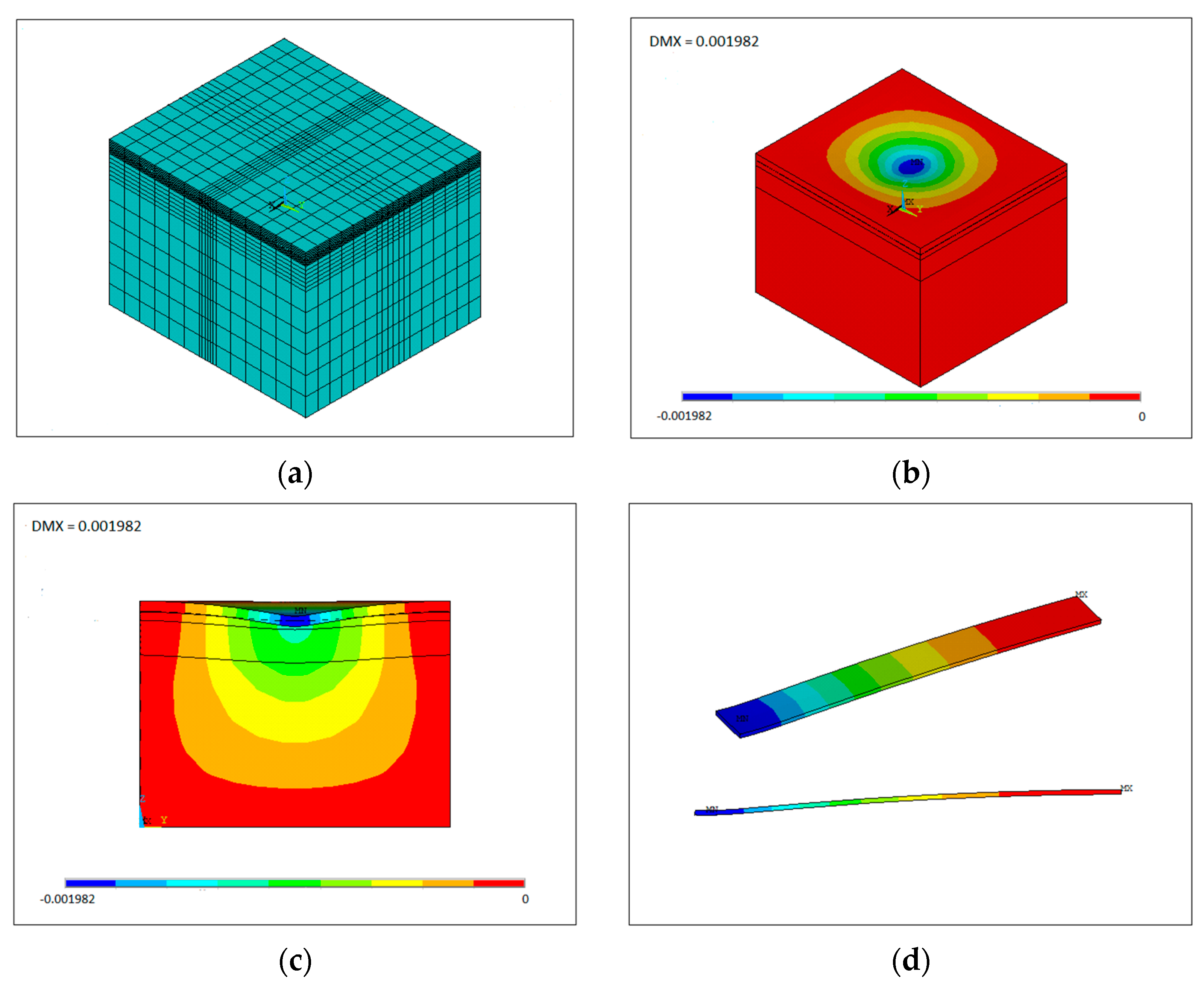
After running the model, a 3-D finite element model was obtained, showing the pavement model with the rutting deformation developed from the load. The solution or outputs expected were surface vertical displacements (rutting depth) and the asphalt, base course, and subgrade stresses and strains subjected by the load. Figure 2a show the 3-D finite element model, Figure 2b show the rutting deformation developed from the load, and Figure 2c show the cross-section view of the rutting deformation used in the analysis of the geo-grid reinforced paved road models. Figure 2d is a half surface strip of the deformed model used to represent the deformation curve. To validate the numerical model, the numerical results were compared with the experimental results. The loading process simulated in this study was as such from the laboratory test at 700 kPa contact pressure. Dynamic loading had no notable impact on the behavior of the geo-grid reinforced pavement for low-stress amplitudes, as verified by Faheem and Hassan (2014) [20].
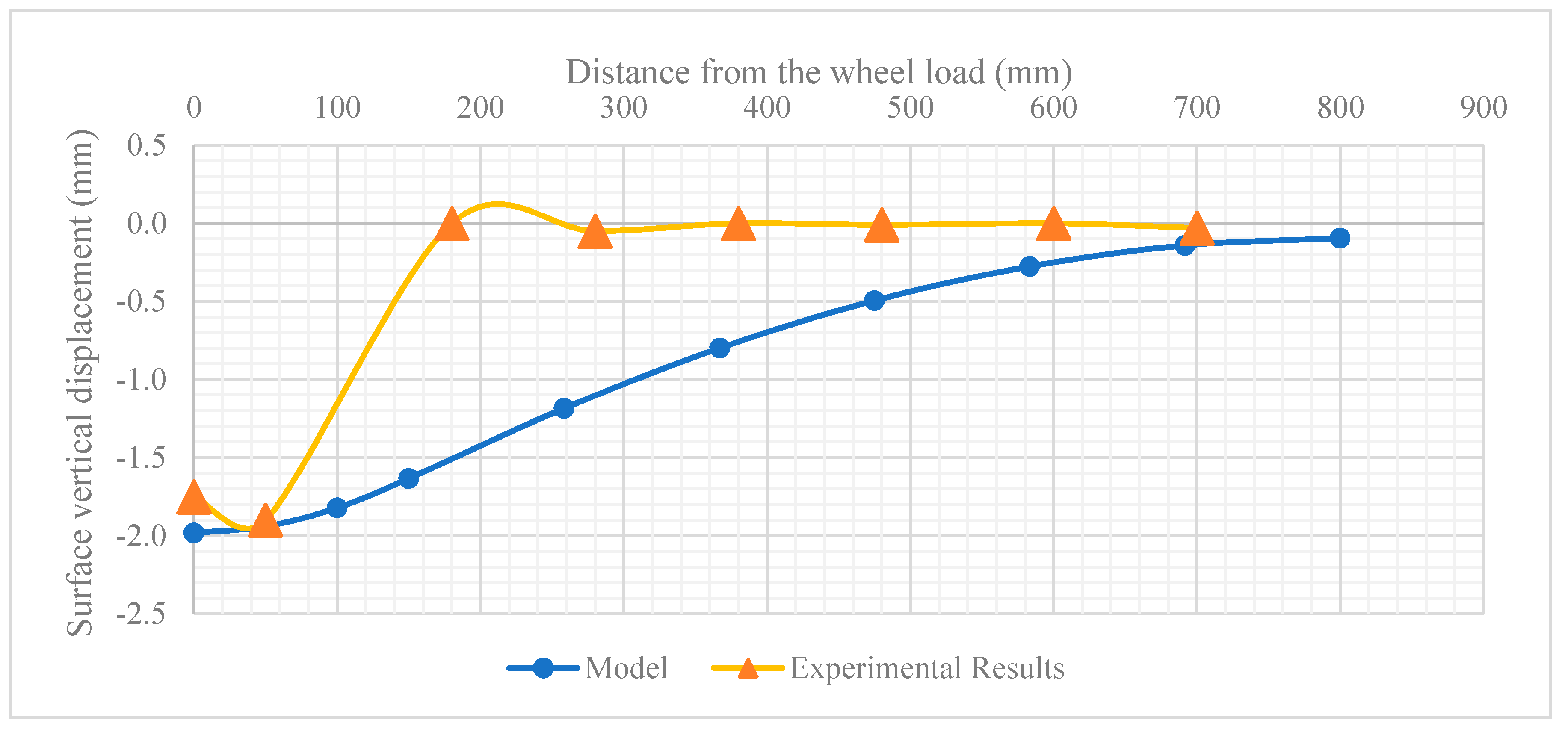
Figure 3 show the comparison between the predicted final rutting profile and the experimental rutting profile of the surface vertical displacement. As shown, the maximum vertical displacements under the wheel load area acquired in the laboratory paved road model were accurately simulated by the finite element model. However, the asphalt upheaval area beside the wheel path seen in the experiment was not shown in the numerical predictions.

4. Finite Element Geo-Grid Position Effect on Reducing Rutting

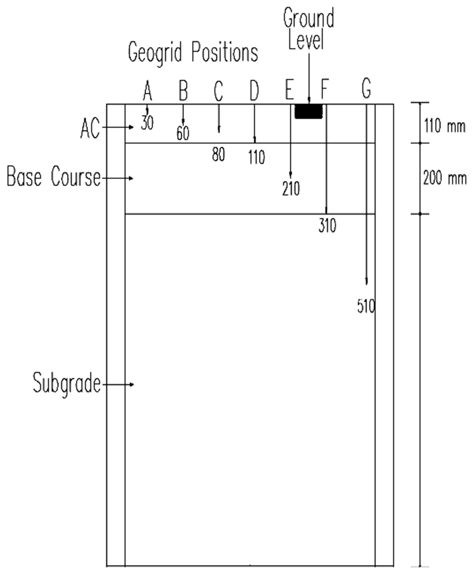
The finite element method used to evaluate the geo-grid position effect on reducing rutting suggested in this study was carried out using the validated geo-grid reinforced FE model focused on assessing the effect of changing the depth position of the geo-grid from the ground surface. The thickness of the asphalt layer (110 mm), the thickness of the base course layer (200 mm), and the subgrade layer (1000 mm) were not changed. The position depth of the geo-grid simulated in the model was (30, 60, 80, 110, 210, 310, 510 mm) respectively, alphabetically ordered as shown in Figure 4.
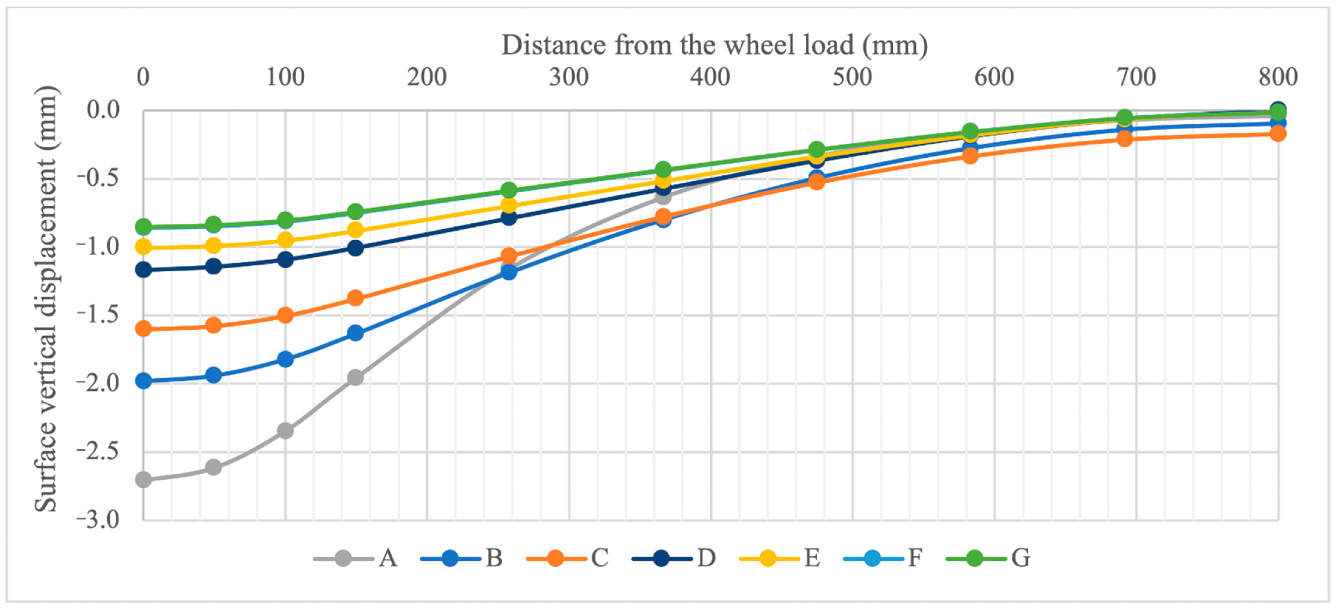
As shown in Figure 5, the surface vertical displacement was affected due to the change in geo-grid depth positioning. It was observed that the deeper the geo-grid was placed, the better the rutting resistance was noticed. When the geo-grid was placed on top of the subgrade (310 mm), the effects of the rutting resistance were best. However, placing the geo-grid lower than that level had no improvement on the surface vertical displacement, as noticed by the overlapped curves of F and G. Position B had 25% rutting resistance improvement compared to position A, position C had 38% improvement compared to position A, position D had 55% improvement compared to position A, position E had 61% improvement compared to position A, and position F and G had 67% improvement compared to position A, by comparing the ratio of the average values for the first 100 mm values.
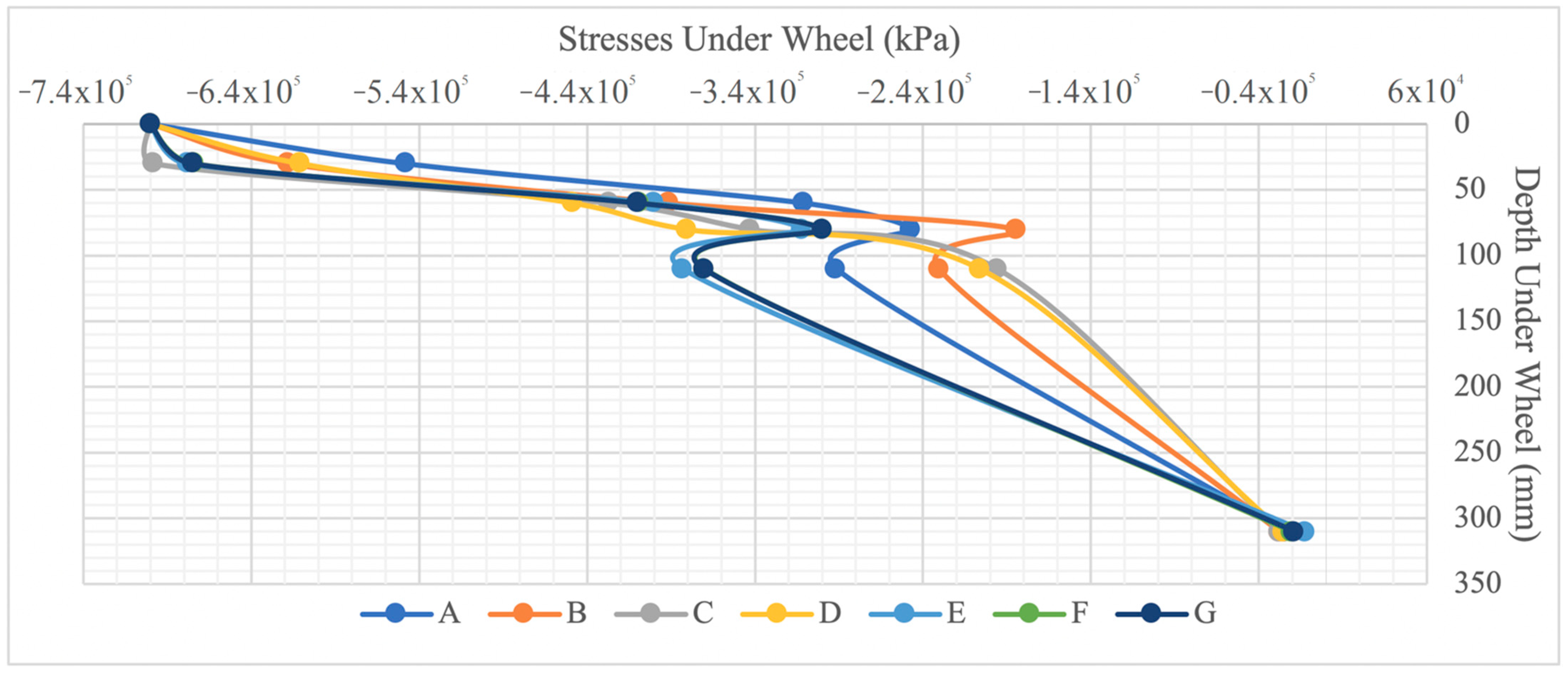
Figure 6 illustrate the effect of the geo-grid depth on the vertical stress distribution in the pavement models, resulting from a parametric evaluation. The negative sign is meant to specify that the stress was compressive. Of course, the stress on contact with the wheel would be the same as the loading condition of 700 kPa contact pressure. The seven different curves representing the different geo-grid depth positioning all show a close path range. However, two out of the seven curves behaved differently. C and D had a different behavior where both were under the lower half of the asphalt layer thickness, which would be the tensile stress side of that layer. Nevertheless, each curve showed a different behavior depending on its depth.

5. Conclusions

In this study, a 3-D finite elements-based model was constructed using ANSYS to analyze the rutting in a geo-grid reinforced flexible pavement. The numerical model was validated by comparing the numerical results with the results from an accelerated large-scale pavement facility experiment. A parametric study was conducted to evaluate the effect of geo-grid depth position. Based on the results, the following conclusions have been drawn:
  • A validated 3-D finite elements model is a great tool to assess the performance of a pavement structure and to apply many parametric studies to it. The finite element model was able to show the asphalt surface vertical displacements and vertical stress distributions in pavement layers with acceptable accuracy.
  • The model does not show the asphalt upheaval area beside the wheel path that is seen in the experiment, which could be due to using a linear elastic constitutive model.
  • Asphalt surface vertical displacement was observed with different geo-grid depth positioning; the deeper the geo-grid is positioned, the more significant the rutting resistance is observed due to stiffness of the geo-grid bearing the tensile force until a certain depth.
  • Vertical compressive stresses under the wheel were also observed with different geo-grid depth positioning and showed noticeable stress reduction by increasing the depth of the geo-grid alone without having to change the geo-grid stiffness.
  • For pavement structures constructed over weak subgrade layers, the geo-grid should be placed in the layers above the subgrade to reduce the stresses before they reach the weak subgrade layers.

Author Contributions

F.A. was involved in conceptualization, data collection, resources, supervision, writing review and editing, and funding acquisition. A.A. and A.E. were involved in conceptualization, methodology, analyzing data, paper writing. S.E. was involved in conceptualization, paper review and editing. M.A. was involved in conceptualization and paper review. All authors have read and agreed to the published version of the manuscript.

Funding

The authors gratefully acknowledge Qassim University, represented by the Deanship of Scientific Research, on the financial support for this research under the number (9907-qec-2019-1-1-Q) during the academic year 1440H/2019AD.

Data Availability Statement

Not applicable.

Acknowledgments

The authors gratefully acknowledge Qassim University, represented by the Deanship of Scientific Research, on the financial support for this research under the number (9907-qec-2019-1-1-Q) during the academic year 1440 AH/2019 AD.

Conflicts of Interest

The authors declare no conflict of interest.

References

  1. Du, Y.; Chen, J.; Han, Z.; Liu, W. A review on solutions for improving rutting resistance of asphalt pavement and test methods. Constr. Build. Mater. 2018, 168, 893–905. [Google Scholar] [CrossRef]
  2. Hammoum, F.; Chabot, A.; St-Laurent, D.; Chollet, H.; Vulturescu, B. Effects of accelerating and decelerating tramway loads on bituminous pavement. Mater. Struct. 2009, 43, 1257–1269. [Google Scholar] [CrossRef]
  3. Shukla, P.K.; Das, A. A re-visit to the development of fatigue and rutting equations used for asphalt pavement design. Int. J. Pavement Eng. 2008, 9, 355–364. [Google Scholar] [CrossRef]
  4. Faruk, A.N.; Lee, S.I.; Zhang, J.; Naik, B.; Walubita, L.F. Measurement of HMA shear resistance potential in the lab: The Simple Punching Shear Test. Constr. Build. Mater. 2015, 99, 62–72. [Google Scholar] [CrossRef]
  5. Norouzi, A.; Kim, D.; Kim, Y.R. Numerical evaluation of pavement design parameters for the fatigue cracking and rutting performance of asphalt pavements. Mater. Struct. 2015, 49, 3619–3634. [Google Scholar] [CrossRef]
  6. Domingos, M.I.; Faxina, A.L. Susceptibility of Asphalt Binders to Rutting: Literature Review. J. Mater. Civ. Eng. 2016, 28, 04015134. [Google Scholar] [CrossRef]
  7. Wang, H.; Al-Qadi, I.L. Evaluation of Surface-Related Pavement Damage due to Tire Braking. Road Mater. Pavement Des. 2010, 11, 101–121. [Google Scholar] [CrossRef]
  8. Li, L.; Huang, X.; Wang, L.; Li, C. Integrated Experimental and Numerical Study on Permanent Deformation of Asphalt Pavement at Intersections. J. Mater. Civ. Eng. 2013, 25, 907–912. [Google Scholar] [CrossRef]
  9. Morea, F.; Agnusdei, J.O.; Zerbino, R. The use of asphalt low shear viscosity to predict permanent deformation performance of asphalt concrete. Mater. Struct. 2010, 44, 1241–1248. [Google Scholar] [CrossRef]
  10. Bildik, S.; Laman, M. Effect of geogrid reinforcement on soil-structure–pipe interaction in terms of bearing capacity, settlement and stress distribution. Geotext. Geomembr. 2020, 48, 844–853. [Google Scholar] [CrossRef]
  11. Qadir, A.; Gazder, U.; Choudhary, K.-U. Statistical analysis for comparing and predicting rutting resistance of asphalt pavements with rigid and flexible geogrid layers. Constr. Build. Mater. 2021, 302, 124136. [Google Scholar] [CrossRef]
  12. Siriwardane, H.; Gondle, R.; Kutuk, B. Analysis of Flexible Pavements Reinforced with Geogrids. Geotech. Geol. Eng. 2008, 28, 287–297. [Google Scholar] [CrossRef]
  13. Sharbaf, M.; Ghafoori, N. Laboratory evaluation of geogrid-reinforced flexible pavements. Transp. Eng. 2021, 4, 100070. [Google Scholar] [CrossRef]
  14. Mittal, A.; Shalinee, S. Effect of Geogrid Reinforcement on Strength, Thickness and Cost of Low-volume Rural Roads. Jordan J. Civ. Eng. 2020, 14, 587–597. [Google Scholar]
  15. Baadiga, R.; Balunaini, U.; Saride, S.; Madhav, M.R. Influence of Geogrid Properties on Rutting and Stress Distribution in Reinforced Flexible Pavements under Repetitive Wheel Loading. J. Mater. Civ. Eng. 2021, 33, 04021338. [Google Scholar] [CrossRef]
  16. Larrain, M.M.M.; Tarefder, R.A. Weibull Model for Rutting Prediction of Warm-Mix Asphalt Agents: Using Hamburg Wheel-Tracking Device Results. Transp. Res. Rec. J. Transp. Res. Board 2016, 2575, 206–212. [Google Scholar] [CrossRef]
  17. Mitchell, M.R.; Link, R.E.; Hong, F.; Chen, D.-H. Calibrating Mechanistic-Empirical Design Guide Permanent Deformation Models Based on Accelerated Pavement Testing. J. Test. Eval. 2009, 37, 31–39. [Google Scholar] [CrossRef]
  18. Ji, X.; Zheng, N.; Hou, Y.; Niu, S. Application of asphalt mixture shear strength to evaluate pavement rutting with accelerated loading facility (ALF). Constr. Build. Mater. 2013, 41, 1–8. [Google Scholar] [CrossRef]
  19. Pandey, S.; Rao, K.R.; Tiwari, D. Effect of geogrid reinforcement on critical responses of bituminous pavements. In Proceedings of the 25th ARRB Conference, Perth, Australia, 23–26 September 2012. [Google Scholar]
  20. Faheem, H.; Hassan, A.M. 2D plaxis finite element modeling of asphalt-concrete pavement reinforced with geogrid. JES J. Eng. Sci. 2014, 42, 1336–1348. [Google Scholar] [CrossRef]
  21. Taherkhani, H.; Jalali, M. Investigating the performance of geosynthetic-reinforced asphaltic pavement under various axle loads using finite-element method. Road Mater. Pavement Des. 2016, 18, 1200–1217. [Google Scholar] [CrossRef]
  22. Al-Jumaili, M.A. Finite element modelling of asphalt concrete pavement reinforced with geogrid by using 3-D plaxis software. Int. J. Mater. Chem. Phys. 2016, 3, 62–70. [Google Scholar]
  23. Correia, N.S.; Esquivel, E.R.; Zornberg, J.G. Finite-Element Evaluations of Geogrid-Reinforced Asphalt Overlays over Flexible Pavements. J. Transp. Eng. Part. B Pavements 2018, 144, 04018020. [Google Scholar] [CrossRef]
  24. Correia, N.S. Performance of Flexible Pavements Enhanced Using Geogrid-Reinforced Asphalt Overlays. Doctoral Dissertation, Sao Carlos School of Engineering of the University of Sao Paulo, Sao Carlos, Brazil, 2014. [Google Scholar] [CrossRef] [Green Version]
  25. Kohnke, P. ANSYS Theory Reference; ANSYS, Inc.: Canonsburg, PA, USA, 1999. [Google Scholar]
Figure 1. Model’s geometry. AC: Asphalt Concrete.
Eng 03 00001 g001
Figure 2. The four figures are as follows; (a) The 3-D finite element model; (b) The rutting deformation developed from the load; (c) Cross-section view of the rutting deformation; (d) Half surface strip of the deformed model.
Eng 03 00001 g002
Figure 3. Final rutting profile from the lab experiment and predicted model.
Eng 03 00001 g003
Figure 4. Representation of geo-grid position depth. AC: Asphalt Concrete.
Eng 03 00001 g004
Figure 5. Surface vertical displacement effect due to geo-grid position.
Eng 03 00001 g005
Figure 6. Surface vertical displacement effect due to geo-grid position.
Eng 03 00001 g006
Table 1. The geometry and material properties implemented into the finite element model.
MaterialSubgradeBase CourseBottom AsphaltTop Asphalt
Thickness1000 mm200 mm50 mm60 mm
Unit Weight18 kN/m322 kN/m325 kN/m325 kN/m3
Cohesion46 kPa0.01 kPa--
Friction Angle26°45°--
Poisson’s Ratio0.400.300.350.35
Young’s Modulus10 MPa100 MPa2500 MPa2500 MPa
Constitutive ModelLinear ElasticLinear ElasticLinear ElasticLinear Elastic
Publisher’s Note: MDPI stays neutral with regard to jurisdictional claims in published maps and institutional affiliations.