Review

A Comprehensive Review on Wireless Power Transfer Systems for Charging Portable Electronics

Department of Electrical and Computer Engineering, Queen’s University, Kingston, ON K7L 4S7, Canada
*
Author to whom correspondence should be addressed.
Eng 2023, 4(2), 1023-1057; https://doi.org/10.3390/eng4020061
Submission received: 6 February 2023 / Revised: 19 March 2023 / Accepted: 30 March 2023 / Published: 3 April 2023
(This article belongs to the Section Electrical and Electronic Engineering)

Abstract

:
Wireless power transfer (WPT) for portable electronic applications has been gaining a lot of interest over the past few decades. This study provides a comprehensive review of the recent advancements in WPT technology, along with the challenges faced in its practical implementation. The modeling and design of WPT systems, including the effect of cross-coupling in multiple receivers, have been discussed and the techniques for efficiency improvement have been highlighted. The challenges of coil design, EMI shielding, and foreign object detection have been pointed out and various cutting-edge solutions have been presented. With improvements in wide bandgap technology, there is a push to operate WPT systems at mega-hertz frequencies. The reason for this is twofold: the miniaturization of the system and the ability to achieve a better magnetic link efficiency. However, with higher frequency comes the challenge of operating the power electronic components efficiently by using soft-switching techniques. Hence, an in-depth discussion on soft-switched topologies such as the Class D and Class E converters and their variations has been provided. Finally, the effects of magnetic field exposure on humans along with safety standards have been discussed.

1. Introduction

The concept of transferring power without wires has been around for over a century. It was first demonstrated by Nikola Tesla in 1891 [1]. He used Michael Faraday’s discovery of electromagnetic induction, in which a current-carrying wire induces a current in adjacent conducting wires [2]. Based on Tesla’s theoretical framework and the advances in fast and more efficient power electronic components (such as silicon, silicon carbide, and gallium nitride devices), near-field WPT has become a reality [3]. Tesla proved that wireless power transmission could be made more efficient if the coils transferring power were in resonance. To operate the system in resonance, the frequency of operation needed to be increased. This required high-frequency switched-mode power converters and conducting wires which have a low AC resistance (e.g., Litz wires [4]). Their inventions led to advances in medical implants with wireless charging in the late 1980s [5,6], inductive power pickup systems, and charging of EVs (electric vehicles) in the 1990s [7,8]. Ever since mobile phones were invented in the 1990s, researchers have been trying to find techniques to charge them wirelessly [9,10,11]. WPT aids in excluding bulky wires which not only makes it more convenient for users, but also makes it better for the environment [12]. With enhanced convenience and frequency of charging with WPT, the capacity of the energy storage systems can be decreased, as well as the size, weight, and cost of the device. Furthermore, transmitters can be easily embedded into furniture, automobiles, computer monitors, etc. Table 1 shows a timeline of the evolution of wireless power charging.
WPT can be broadly classified into radiative and non-radiative methods as shown in Figure 1. Radiative power transfer takes place over long distances (which are much greater than the antenna size) using electromagnetic waves [21]. Some examples may include power transfer through radiofrequency [22], microwave [23], optical [24], and ultrasonic [25] technologies. However, owing to the omnidirectional nature of the power transfer, the overall system efficiency is quite low in this method. Hence, non-radiative methods are preferred for near-field applications. Non-radiative methods rely on magnetic or electric field coupling, which includes capacitive and inductive wireless power transfer, as shown in Figure 2.
Capacitive power transfer (CPT) takes place using time-varying electric fields. Electric fields start and terminate at the conductive plates in CPT because of positive and negative charges on the plates. As a result of the constrained E-field, CPT systems do not induce eddy currents in nearby objects and do not require ferrites, which reduces the size and weight of the system. Furthermore, CPT systems [26,27,28,29,30,31,32] are more tolerant of misalignment and have fewer EMI shielding requirements. Inductive power transfer (IPT) occurs by using time-varying magnetic fields. Due to the absence of magnetic monopoles, magnetic field lines flow through the coils and loop back to the source and hence this magnetic field path needs to be monitored and guided. In IPT, the voltage induced across the receiver coil depends on the permeability of free space, whereas in CPT, the displacement current that is going to flow through the coupler depends on the permittivity of free space. The biggest benefit of using magnetic fields for wireless power transfer is the difference between the permeability and permittivity of free space, where the former is five orders of magnitude higher than the latter. This shows that for the same size of couplers and distance between them, the intensity of electric fields needs to be many orders of magnitude more to produce comparable displacement currents in CPT, as induced voltages are produced in IPT [28]. Furthermore, if the dielectric between the two plates in a CPT system is air, the capacitance value is relatively low (a few pF). This makes the system very sensitive to parameter variations such as parasitic capacitances near the plates or interwinding capacitances of the compensating inductors [27]. Hence, the plate sizes need to be larger or the air gap between them must be reduced. For these reasons, IPT is preferred for portable electronic applications with multiple receivers where the distance between the transmitter and receiver needs to be greater. Table 2 shows a summary of the comparison between inductive and capacitive coupling.
Both capacitive and inductive power transfer can be made more efficient by operating the WPT systems in the megahertz range. A higher frequency of operation also miniaturizes the magnetic components and improves the power density of the system. Silicon (Si) MOSFETs are not preferred for MHz frequency operation because of higher switching losses. This is due to slower turn-on and turn-off times caused by higher values of gate capacitances. Hence, wide band gap (WBG) devices such as silicon carbide and gallium nitride are preferred for these applications since they have a higher electron saturation velocity [33]. Furthermore, the WBG devices have a lower on-state resistance ( R d s , o n ) because of the high critical electric field [34]. They also have a higher breakdown voltage compared to Si devices due to the wider energy band gap [33].
Compared to the GaN MOSFET, SiC has a lower R d s , o n at room temperature and can operate at much higher temperatures than Si and GaN MOSFETs as they have lower leakage currents and higher thermal conductivities. The R d s , o n of GaN MOSFETs varies significantly with temperature variations [33]. However, since the SiC MOSFETs have higher input capacitances ( C i s s ) and gate resistances ( R G ), their maximum switching frequency is lower than GaN devices and they have increased gate drive losses. The breakdown voltages of GaN devices can also be increased by using vertical structures instead of lateral structures [35]. Gallium oxide and diamond are some other materials that are being researched for their ultra-wide band gap properties.
WPT has been used in a wide range of applications including charging of portable electronics [36,37,38,39,40], electric vehicles [41,42,43,44,45], electric drones, automated guided vehicles (AGV) [46,47,48,49,50], medical implants [51,52,53,54,55], plasma generation [56], and automation in factories [57,58,59,60]. There are two main standards for inductive WPT today: Qi and AirFuel Alliance. Table 3 shows the specifications of Qi and AirFuel charging standards [61].
The basic architecture of a WPT system to power multiple portable electronic devices is shown in Figure 3. From the AC supply line, the low-frequency AC voltage is first converted to a DC using a power factor correction (PFC) rectifier [62,63]. The DC voltage is then converted to AC using a high-frequency inverter or power amplifier topology, which then drives the transmitter coil through a compensation network. The power sent by the coil using magnetic fields is picked up by the receiver coils. After passing through the compensation network, the receiver current is rectified and conditioned using a DC-DC converter based on the load requirement. To reduce the number of components and decrease the losses in the power electronics, the PFC rectifier and the high-frequency inverter stages can be combined into one AC-to-AC conversion stage [64]. The rectifier can also be combined with the power conditioning unit on the receiver to form an integrated active rectifier [65], which can provide constant voltage or constant current control for charging the batteries of the portable electronics.
Many articles have reviewed WPT techniques owing to its wide scope of applications [66,67,68]. Ref. [66] gives a comparision of near-field and far-field techniques with an emphasis on the shape and material of coils and their positioning. Ref. [67] presents the modeling and efficiency optimization techniques of WPT systems, giving more emphasis on static and dynamic charging of electric vehicles. Ref. [68] presents the optimization techniques of coil design, repeaters, compensation networks, etc., while highlighting some issues faced in WPT design. In this paper, all the fundamental topics have been covered, including inverter and rectifier topologies, coil design, modeling of WPT systems, compensation networks, EMI issues, etc. This provides a base for engineers who are beginning with this topic. In addition to the basics, this paper also discusses advanced and complicated topics, which have not been shown in such depth in previous review papers. One of these topics is the efficiency optimization of WPT systems in the presence of cross-coupling among receivers. The benefits of using constant current source transmitters for multiple receiver systems have been highlighted. Coil design has been discussed from the point of view of coupling improvement as well as quality factor improvement. Newer coil designs such as self-resonating coils, solenoidal coils, three-dimensional omnidirectional coils, and interleaved coil structures have been discussed. Various soft-switched topologies have been discussed and their merits and demerits have been compared.

2. Wireless Power Transfer System Modeling and Efficiency Optimization Techniques

Similar to the modeling of resonant converters, WPT systems can be analyzed in the frequency domain [69,70,71,72] and tim domain [73,74]. Time-domain modeling gives more accurate results and can model the discontinuous conduction modes (DCM) of the WPT system. However, the application of time-domain modeling requires information about the equivalent states of the circuit which can be obtained using simulations or through experiments. If the series resistances of coils, ESR of capacitors, and on-state resistances of the semiconductors are added to the analysis, the differential equations can have exponential terms in them which can make the solutions quite involved and closed-form solutions might be unattainable. Furthermore, time-domain modeling cannot be extended to analyze multiple receivers, with cross-coupling among them, since closed-form solutions do not exist [75]. Hence, the frequency-domain model of such systems is more beneficial. The most widely used technique is the first harmonic approximation (FHA). The simple closed-form solutions obtained from FHA can give an overall idea about the system. The voltages and currents in the system are approximated as sinusoids with one frequency. However, this technique might not be optimum for design since it may lead to overdesign or underdesign of components in the case where more dominant harmonics are present in the voltage and current waveforms. Hence, considering harmonics on both source and load sides [69,70,71] is beneficial for design purposes and can easily be extended to multiple receivers.
The objective of a WPT system in portable electronics applications is to be able to deliver the required amount of power to the device with the highest possible efficiency. A WPT system is a combination of various power conversion stages, such as DC-AC, AC-AC, and AC-DC. Each of these stages has a unique point of operation that maximizes its efficiency, in terms of operating frequency or load resistance. Hence, many studies have focused on improving the overall efficiency of the system using a system-level design problem [76]. This section focuses on ways to improve wireless link efficiency.

2.1. Model of a WPT System Using Series-Series Compensation

A simplified lumped parameter model of a WPT system using FHA is shown in Figure 4a. The transmitter consists of an AC voltage source, a compensation capacitor, and the transmitting coil. The AC voltage source is most commonly a high-frequency inverter or a power amplifier which drives the transmitter coil. The most used compensation network is the series-series configuration but some other widely used networks include LCL [77], LCC [78,79], LC/S [80], etc. The series resistance is the sum of coil resistance, ESR of compensating capacitors, and any resistance from the source. The receiver comprises a coil, a compensating capacitor, and a load. The load can be AC or DC. In case it is a DC load, which is typically the case with battery charging applications, then the load is preceded by a rectifier and a power conditioning unit (typically a DC-DC converter). The coupled inductance can also be modeled as two dependent voltage sources on the transmitter and receiver as shown in Figure 4b. Other commonly used models of the WPT coils are the T-transformer network and the cantilever model; however, the coupled inductor model is the most widely used. A list of notations for the components used in Figure 4 and variables used in Equations (1)–(8) have been added below.
  • V i n —peak value of the sinusoidal voltage source.
  • ω s —switching frequency in rad/s.
  • M 12 —mutual inductance between the transmitter and receiver coils.
  • k 12 —coupling coefficient between the transmitter and receiver coils.
  • R 1 —series resistance of the transmitter coil (includes on-state resistance of switches and resistances (ESRs) of the transmitter coil and compensation capacitors).
  • R 2 —series resistance of the receiver coil (includes series resistance of diodes and resistances (ESsR) of the receiver coil and compensation capacitors).
  • C 1 —equivalent series compensation capacitance of the transmitter.
  • C 2 —equivalent series compensation capacitance of the receiver.
  • L 1 —coil inductance of the transmitter.
  • L 2 —coil inductance of the receiver.
  • R L —load resistance.
  • i 1 —peak value of the sinusoidal current flowing in the transmitter coil.
  • i 2 —peak value of the sinusoidal current flowing in the receiver coil.
  • X 2 —series reactance of the receiver side.
  • i 1 r m s —rms value of the sinusoidal current flowing in the transmitter coil.
  • i 2 r m s —rms value of the sinusoidal current flowing in the receiver coil.
  • ω —relative resonant frequency of the receiver.
  • ω r —resonant frequency of the receiver.
  • Q L —loaded quality factor of the receiver.
  • Q p —unloaded quality factor of the transmitter.
  • Q s —unloaded quality factor of the receiver.
The KVL equations for the model in Figure 4 can be given as:
V i n = ( R 1 + 1 j ω s C 1 + j ω s L 1 ) i 1 + j ω s M 12 i 2
j ω s M 12 i 1 + ( R 2 + R L + 1 j ω s C 2 + j ω s L 2 ) i 2 = 0
The mutual inductance between the coils can be given as:
M 12 = k 12 L 1 L 2
The system efficiency ( η ) can be given as:
η = i 2 r m s 2 R L i 1 r m s 2 R 1 + i 2 r m s 2 ( R 2 + R L ) = R L ( i 1 i 2 ) 2 + R 2 + R L = ω s 2 M 12 2 R L ( ( R 2 + R L ) 2 + X 2 2 ) R 1 + w s 2 M 12 2 ( R 2 + R L )
where the receiver reactance X 2 = ω s L 2 1 / ω s C 2 .
The relative resonant frequency is defined as ω = ω s / ω r , where ω r is defined as ω r = 1 L 2 C 2 . Now, from Equation (4), the relative resonant frequency, which yields the maximum efficiency, can be found by differentiating η with respect to ω . It can be shown as:
ω = 1 1 1 2 Q L 2
where Q L = L 2 / C 2 R 2 + R L is the loaded Q-factor of the receiver. From Equation (5), if the quality factor of the system is low, then the switching frequency for the optimizing efficiency is slightly above the resonant frequency of the receiver. However, if the loaded quality factor is high, then the system efficiency is optimized when the switching frequency is made equal to the resonant frequency of the receiver. When the loaded quality factor is high (>2, which is the case with most practical WPT systems), the efficiency can be optimized when X 2 = 0 . Hence, ω r = ω s and ω = 1 . Now, the optimum value of the load resistance, R L ( R L , o p t ), which yields the highest efficiency at resonance is:
R L , o p t = R 2 1 + ω s 2 M 12 2 R 1 R 2
Substituting R L , o p t into Equation (4), the system efficiency, η , becomes:
η = k 12 2 Q p Q s ( 1 + 1 + k 12 2 Q p Q s ) 2
where Q p = L 1 / C 1 R 1 and Q s = L 2 / C 2 R 2 . From Equation (7), the efficiency of the system can be maximized by increasing the term k 12 2 Q p Q s , often known as the k-Q product of the system [81]. The efficiency of the system is plotted as a function of the k-Q product in Figure 5a and is seen to be monotonically increasing.
Thus, by using coils of high quality factor, one can obtain a higher transfer distance or higher tolerance to misalignment between the coils for the same amount of link efficiency. Figure 5b shows the Q-factor of the coils with respect to frequency. As the frequency increases, the quality factor of the coil increases at first. The AC resistance of the coil increases as well due to the skin effect, but the increase is much lower than the product of frequency and self-inductance. However, at very high frequencies, when the wavelength of the field produced is comparable to the length of the coils, the coils start to act as antennae and radiate power. The AC resistance of the coils starts to increase much more than the product of frequency and self-inductance, and the Q-factor of the coils starts decreasing fast. As shown in Figure 5b, for a coil of radius 10 cm and three turns, the radiation effect starts to occur at a frequency of nearly 10 MHz. Hence, if the system is operating at a few MHz below the point of dominant radiation effects, a good link efficiency can be achieved. A Q-factor above 1000 is achievable in practical systems if operated in the MHz region, and therefore there is a push to operate WPT systems in MHz frequencies to maximize coil-to-coil efficiency. However, the losses in the power electronics circuitry become very prominent at such frequencies and thus must be considered during the design.
In multiple receiver applications, the coupling between the transmitter and receivers is generally quite low. Hence, having a higher quality factor of coils can offset the reduction in efficiency due to the low coupling coefficient. If there are N R receivers with no cross-coupling between them and if the optimal load resistance for each receiver obtained from [76] is substituted in the efficiency equation, the following equation for the efficiency of the link is obtained:
η = N R k 1 i 2 Q p Q s i ( 1 + 1 + N R k 1 i 2 Q p Q s i ) 2
where k 1 i denotes the coupling coefficient and Q s i denotes the unloaded quality factor of the i t h receiver. Equation (8) shows that more receivers increase the k-Q product of the system, which in turn increases the efficiency.

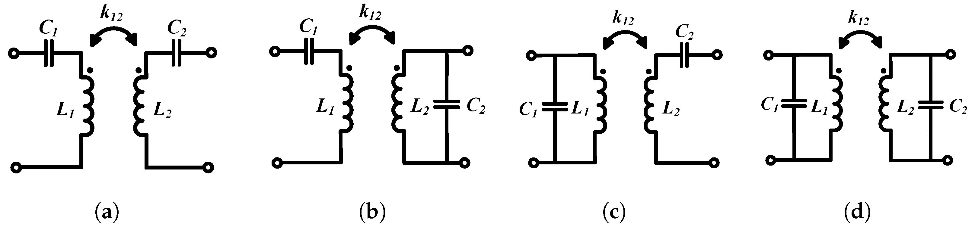
2.2. Compensation Networks

The inductance of the coil in the receiver circuit of the WPT system needs to be compensated for to increase the efficiency of the system, and the inductance of the coil in the transmitter circuit needs to be compensated for to reduce the VA rating of the input power. There are four basic compensation topologies, namely series-series (SS), series-parallel (SP), parallel-parallel (PP), and parallel-series (PS), based on the connection of the resonant capacitance, as shown in Figure 6. Current-driven topologies are used with series resonant receiver circuits and voltage-driven topologies are used with parallel resonant receiver circuits. With a series resonant receiver coil, the benefit is that even if the load resistance varies or the coupling coefficient between the coil changes, the series-tuned circuit still reflects a purely resistive load to the primary coil. With parallel resonance on the receiver, when the load resistance changes, it reflects reactance along with resistance back to the primary, and hence the circuit is detuned and the soft-switching capability might be lost. Hence, series resonant tuning is preferred on the receiver side.
The LCC compensation topology is also widely used in wireless power transfer [78,79,82,83,84]. This compensation can be applied to the transmitter side (LCC-S [82]), as shown in Figure 7a, or to the transmitter as well as the receiver side (LCC-LCC [83]), as shown in Figure 7b. The power transfer characteristics of the SS topology can have two peaks as a function of the frequency and quality factor of the system. This makes the controller design with frequency modulation quite complicated [70], since it is uncertain whether there is an increment or decrement in the output power with a change in frequency. When compared with the SS compensated topology, the power characteristic of LCC-S appears to be unimodal as a function of the frequency and quality factor [78], making the controller design with frequency modulation easier. In the LCC-LCC topology, the power transferred to the load monotonically increases with increases in switching frequency, quality factor, and coupling coefficient. In both LCC-S and LCC-LCC topologies, the power transfer capability drops with a decrease in the coupling factor. To transfer the rated power with low values of coupling, the quality factor of the system needs to be increased. This requires a larger value of inductance, which reduces the power density of the system and increases the cost. Therefore, it is not an optimal solution. Hence, Ref. [78] proposes parameter tuning of the parallel compensation capacitors instead of frequency tuning to maintain the rated power delivery of the system over a wide range of coupling conditions.
The LCC topology can also greatly mitigate the magnetic field produced by the coils and reduce conducted emissions [84] to meet the EMI and EMF safety guidelines. One disadvantage of the LCC topology is the increased number of passive components required for the compensation network which can make the system bulky. Hence, this topology is more useful for higher power transfer applications. The increased number of components, however, gives more flexibility in parameter design for better tolerance to misalignment [78].

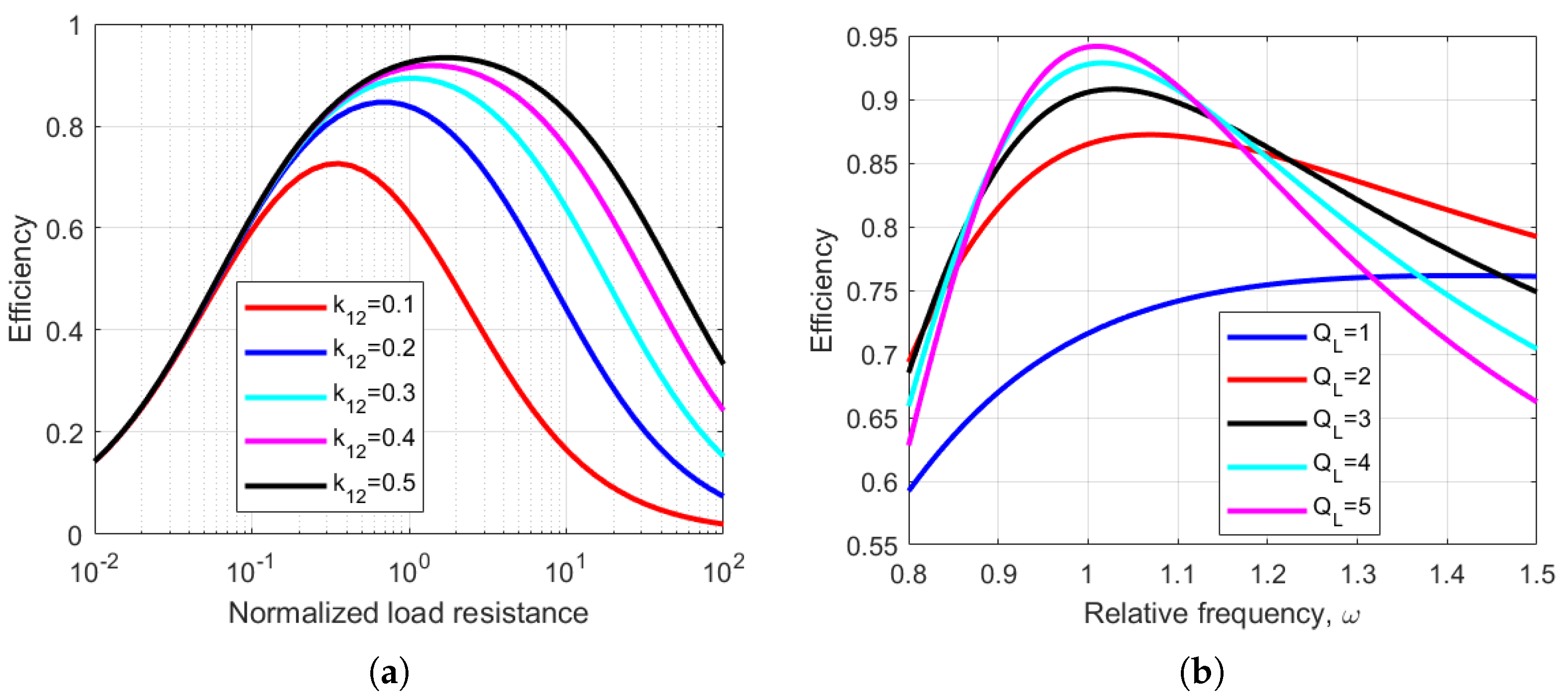
2.3. Maximizing Power Transfer between the Transmitter and Receiver

Maximum power transfer takes place in a WPT system when the source impedance is matched with the load impedance. The maximum power transfer and maximum energy efficiency do not necessarily happen simultaneously. The maximum energy efficiency occurs when the source impedance is minimized and the load impedance is optimized, and they are not necessarily equal. As a result of impedance matching, the efficiency of the system under the maximum power transfer approach cannot be above 50 % [85]. Hence, this technique is suitable only for very low power applications (<1 W) which require sufficient power delivery over a greater distance.

2.4. Efficiency Optimization Techniques

Most common loads of WPT systems such as batteries do not have a constant resistance. During battery charging, the load current and the equivalent load resistance vary with time. The efficiency of the system is optimized at a specific load resistance. This can be observed in Figure 8a, where the efficiency of a WPT system has been plotted as a function of normalized load resistance for various values of coupling coefficients. Four commonly used techniques can transform the reflected load to the optimum value.

2.4.1. Using Impedance Matching with Reconfigurable Resonant Circuits

The resonant frequency of a WPT system can be changed by using reconfigurable resonant components such as a switched capacitor array or switchable coil structures. In this way, the resonant frequency of the system can be changed without changing the switching frequency to achieve optimal energy efficiency in the event of load changes [86]. However, these systems require a high number of components to provide enough discrete steps of changes in resonant frequency for fine-tuning the system.

2.4.2. Using Variable Operating Frequency

As shown in Section 2.3, using Equation (5), when the loaded Q-factor is low, the operating frequency can be increased to achieve a higher efficiency. This has also been shown in Figure 8b, where the system efficiency has been plotted with respect to the relative frequency for various values of loaded Q-factors. This concept has been used in [87] to develop a variable frequency-based phase shift modulated WPT inverter for maximum energy efficiency tracking. However, only if the rated value of resistance is much higher than the optimum value of resistance is the efficiency improvement prominent.

2.4.3. Using Impedance Compression Networks

An impedance compression network (ICN) [88] can be used to narrow down the range of load variations as seen by the inverter due to misalignment or load variations. It is an additional passive network made with only inductors and capacitors, which does not require control circuitry. An ICN comprises a resistance compression network (RCN) and a phase compression network (PCN). The RCN minimizes the magnitude variations in the reflected impedance seen by the inverter. The PCN minimizes phase shift variations caused due to load reflection. A Smith chart can be used to design the PCN.

2.4.4. Using DC-DC Converters for modulating Load Impedance

Using DC-DC converters to alter the load resistance is a popular approach because of the flexibility in the control of the power converter to optimize efficiency in real time under varying conditions. A buck-boost converter was used after the rectifier on the receiver side for maximum energy efficiency tracking in [89]. The minimum input power to the system is found for a given output power using a perturb-and-observe algorithm. Receiver-side control maintains a constant power output and voltage regulation of the system. The system does not require a wireless communication link for tracking the optimal load.

2.5. WPT Systems with Multiple Coils

Wireless power transfer systems can consist of multiple transmitters or receivers or intermediate coils which act as domino resonators. This section describes different systems with more than one path for the power to flow from the transmitters to the receivers.

2.5.1. Intermediate Multiple Coils Acting as Repeaters or Domino Resonators

Multiple resonators or repeaters can be added in between transmitter and receiver coils in WPT systems for different applications. This enables transmission of power over larger distances or along a curved path such as in the case of a robot arm. The two main reasons for such configurations are:
1.
Multiple intermediate coils introduce more degrees of freedom which can be utilized for improving efficiency or making the wireless link less sensitive to coupling variations.
2.
The intermediate coils can also act as effective impedance matching elements [90] on both the source and load sides.

2.5.2. Multiple Transmitter Coil Systems

Multiple transmitter coils are mostly applied in two areas: (a) dynamic WPT and (b) systems that require misalignment tolerance. In dynamic WPT systems, the receiver is in motion. Multiple transmitter coils are connected to one power source and have to be powered effectively based on the location of the receiver. The current flows in the transmitter coils to which the receiver is aligned, while other transmitter coils are not charged. By using multiple transmitter coils, one can also generate a nearly uniform magnetic field over a surface, allowing some tolerance to misalignment of the receiver [85].

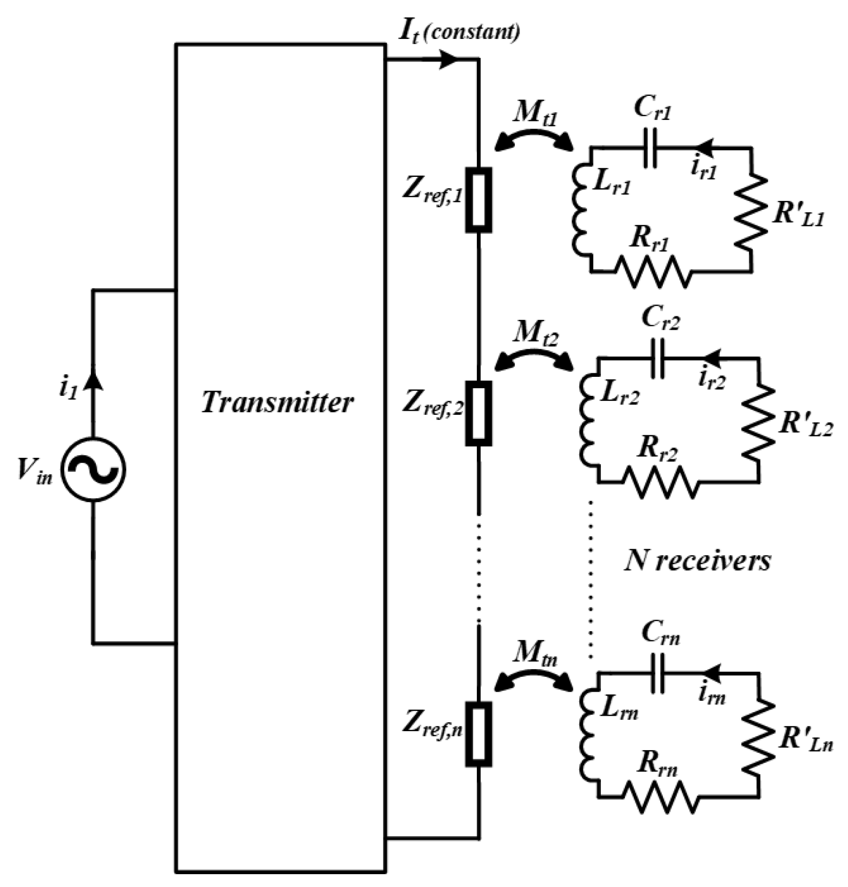
2.5.3. Multiple Receiver Coil Systems

In some WPT applications, multiple receivers are needed to be powered simultaneously from a single transmitter system. As shown in Section 2.1, adding more receivers can improve link efficiency. However, the addition of multiple receivers reduces their coupling coefficients with the transmitter because of spatial constraints. Hence, quality factors of the coils need to be increased, which can be achieved by operating the system in the MHz range. In practice, there are many uncertainties with multiple receiver systems, such as variations in the coupling and load and addition or removal of receivers. Therefore, it is necessary to have a robust system with proper design and control. The most common control objective is to maximize the system’s efficiency while maintaining voltage regulation at the output. To ensure voltage regulation at the output of the receivers, a DC-DC converter is commonly used [91,92]. Voltage regulation can be maintained with wide variations in load or coupling if the input voltage to the system is sufficiently large. However, a large input voltage leads to inefficient operation of the system.

Efficiency Optimization of Multiple Receiver WPT Systems without Cross-Coupling among the Receivers

Some ways to improve efficiency while maintaining voltage regulation are by input voltage regulation [92], load resistance optimization [76], frequency tuning of the transmitter, and dynamic impedance matching (IM). However, considering the narrow ISM band, a fixed frequency is preferred for MHz WPT systems. Furthermore, switch-based IM networks require complicated circuits and control and are not preferred. Hence, commonly used efficiency optimization techniques are:
1.
Input Voltage Regulation—The efficiency of the system is highly dependent on the input voltage at various conditions of load and coupling. Using modulation techniques such as phase shift or pulse width modulation, the RMS input voltage to the WPT system can be varied. Another way is to use a DC-DC converter in front of the inverter or power amplifier on the transmitter side to provide the required input voltage. However, this increases the number of components as well as the losses in the system.
2.
Optimizing the Load Resistance seen by the Receivers—The efficiency of a system with multiple receivers can be maximized by optimizing the load resistances seen by each of the receivers. The optimum value of the load resistances ( R L , o p t ) can be given by the equation below [76]:
R L , o p t = R i 1 + i = 1 n ω s 2 M 1 i 2 R 1 R i
where R i is the series resistance of the i t h receiver and M 1 i is the mutual inductance between the transmitter and the i t h receiver. However, constant optimization of all the load resistances with variations in load and couplings requires a considerable control effort and sensing circuitry and hence is not very practical.

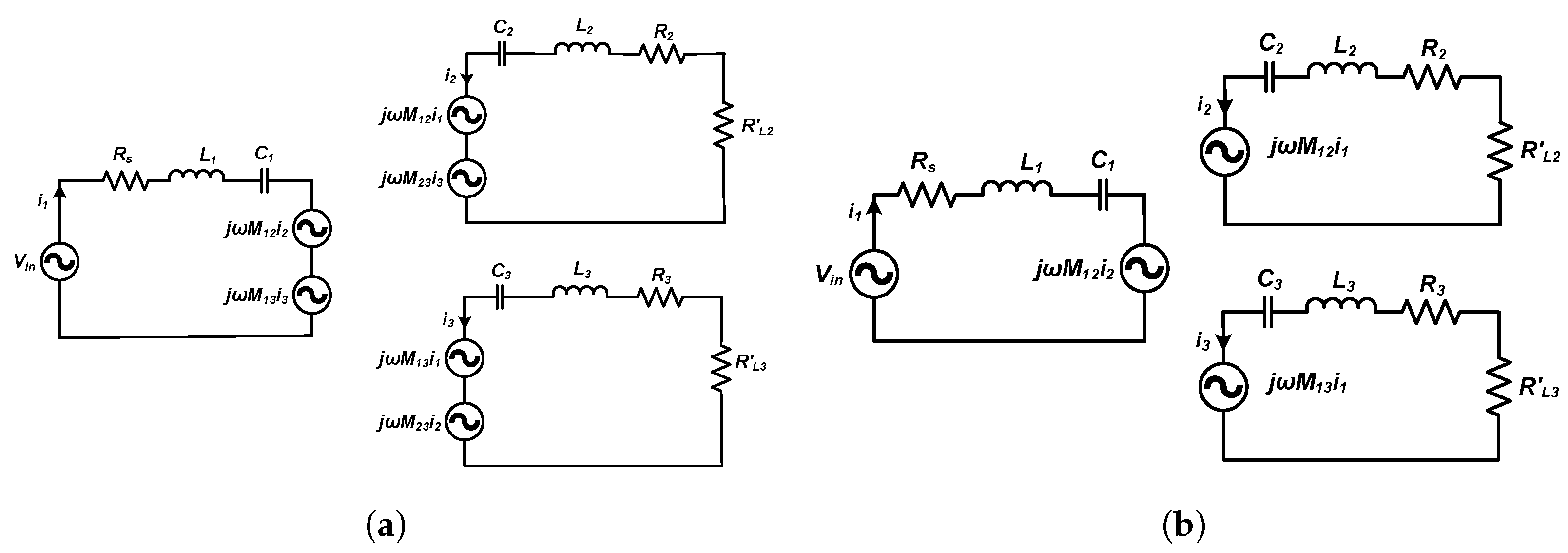
Efficiency Optimization of Multiple Receiver WPT Systems with Cross-Coupling among the Receivers

In WPT systems with multiple receivers, cross-coupling among receivers presents one of the biggest design challenges. Cross-coupling complicates the control design, interferes with the power distribution among the receivers, and can reduce the system efficiency [93]. A lot of research has been performed to eliminate or reduce the effect of cross-coupling among the receivers by adjusting the reactance on the receiver side [94,95,96,97,98,99,100,101,102,103,104,105,106,107]. One way to mitigate the effect of cross-coupling among receivers is by using multi-resonant WPT systems [95,96,97], where each receiver resonates at one of the carrier frequencies of the transmitter. However, this is not a preferred method because using multiple frequencies cause higher AC losses in the windings. Furthermore, to avoid interference, the distances between the frequency bands need to be increased, and this limits the number of receivers. Using coil decoupling [98,99,100], the cross-coupled flux among the receiver coils can be cancelled out by using a suitable design and orientation.
In [99], a bucking coil layout was used, where the winding direction of one of the coils was alternated to cancel out the flux linked between the coils. Using time-division multiplexing, the influence of cross-coupling can be naturally avoided since only one receiver is powered at a time [101,102]. However, this technique limits the total amount of power transferred to the receivers. A passive compensation technique with parameter optimization and system-level design has been used in [103]. However, information on the coupling and load variation range among all the receivers is required before the design. Then, an objective function is formulated with the given constraints which can be solved through non-linear optimization techniques such as game theory or genetic algorithms. However, WPT system designs with passive compensation are suitable only for a narrow range of parameters. With active compensation [94,104], the voltage induced due to the cross-coupling among coils can be canceled out by injecting a certain amount of reactance. However, this reactance is dependent on the coupling and load conditions of all the coils, which change in real time [94]. Furthermore, the estimation of these parameters requires complicated circuitry [105]. By controlling the phase difference between the transmitter and receiver currents and making them orthogonal, the effect of cross-coupling can be reduced [106,107]. However, the assumption of the current quadrature phenomena [106] is only valid if higher-order harmonics are ignored. This is not a good assumption when the system has a low Q-factor or is operating at a light load. Table 4 shows a comparison of various techniques to reduce the effect of cross-coupling among receivers in WPT systems.
Figure 9a shows the first harmonic model of a WPT circuit with two receivers with cross-coupling between them. A list of notations for the components used in Figure 9 and variables used in Equations (10)–(15) have been added below.
  • M 1 k —mutual inductance between the transmitter and the k t h receiver coil.
  • M i k —mutual inductance between the i t h and k t h receiver coil.
  • R s —series resistance of the transmitter coil (includes on-state resistance of switches and resistances (ESRs) of the transmitter coil and compensation capacitors).
  • R i —series resistance of the i t h receiver coil (includes series resistance of diodes and resistances (ESsR) of the receiver coil and compensation capacitors).
  • C 1 —equivalent series compensation capacitance of the transmitter.
  • C i —equivalent series compensation capacitance of the i t h receiver.
  • L 1 —coil inductance of the transmitter.
  • L i —coil inductance of the i t h receiver.
  • R L i —load resistance of the i t h receiver.
  • i 1 —peak value of the sinusoidal current flowing in the transmitter coil.
  • i i —peak value of the sinusoidal current flowing in the i t h receiver coil.
  • X 2 —series reactance of the first receiver.
  • X i —series reactance of the i t h receiver.
Using KVL, the equations of the circuit can be written as follows:
V i n = ( R s + j X 1 ) i 1 + j ω s M 12 i 2 + j ω s M 13 i 3
j ω s M 12 i 1 + ( R 2 + R L 2 + j X 2 ) i 2 + j ω s M 23 i 3 = 0
j ω s M 13 i 1 + j ω s M 23 i 2 + ( R 3 + R L 3 + j X 3 ) i 3 = 0
Hence, the receiver reactances which can nullify the effect of cross-coupling among receivers is given by:
X 2 = ω s M 13 M 23 ( R L 2 + R 2 ) M 12 ( R L 3 + R 3 )
and
X 3 = ω s M 12 M 23 ( R L 3 + R 3 ) M 13 ( R L 2 + R 2 )
For multiple receiver systems, the reactance can be given by:
X i = k = 2 , k i n ω s M 1 k M i k ( R L i + R i ) M 1 i ( R L k + R k )
The FHA model of a system without cross-coupling among the receivers is shown in Figure 9. The elimination of this cross-coupling does not always lead to the optimal efficiency point. In some cases, it aids in improving the efficiency [108,109]. Cross-coupling changes the resonant frequency of the inductive link. This resonant point can be varied by changing the net reactance of the receivers. A switched capacitor circuit was used for this purpose in [75]. In [108], a perturbation and observation algorithm was used to vary the resonant frequency of the inductive link. However, this technique uses a fixed step to change the control angle of the switched capacitor. In [109], a dynamic tracking algorithm was proposed for maximum efficiency tracking. This technique uses a variable step size based on the gradient descent method and reaches the maximum efficiency point faster than in [108]. All of these active compensation techniques require the use of a communication network among the transmitter and receivers to optimize the efficiency in real-time.

3. Inverter, Rectifier, and Compensation Topologies for Wireless Power Transfer

In Section 2, it has been shown that the coil-to-coil link efficiency of a WPT system can be increased by increasing the switching frequency up to the point where radiation effects start to become overwhelming. For most WPT coil structures, the optimum quality factor is obtained when they are operated in the MHz switching frequency region. One of the main challenges in constructing these MHz WPT systems is operating the inverters and rectifiers efficiently at such high frequencies.

3.1. Inverter Topologies

To ensure the high efficiency of the inverters, losses in the semiconductor devices must be minimized. The major sources of power losses in semiconductor devices are conduction losses and switching losses. When the switching frequency is increased, the optimal load resistance in Equation (6) also increases. Thus, for a given output power, one can operate at a higher voltage and lower current on the transmitter side. This reduces conduction losses on the switch, since they are proportional to the square of the current. Switching losses are proportional to the frequency of operation and can be significant at MHz frequencies. However, switching losses can be almost eliminated using soft-switching techniques. There are several types of DC-AC power inverters in the MHz frequency range which can achieve soft-switching such as the class D, class E, and class EF inverter topologies.

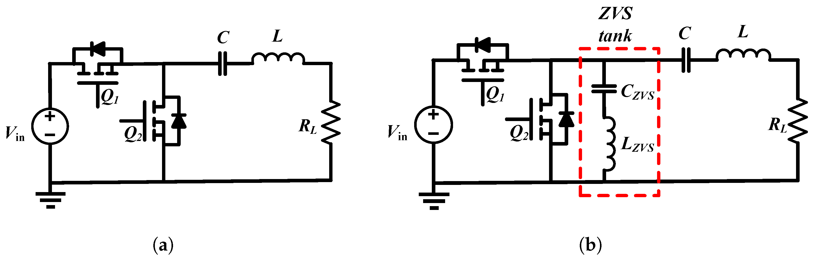
3.1.1. Class D Topology

The circuit of a class D resonant inverter is shown in Figure 10a. The two switches have a complementary operation to one another, with a suitable dead time, and produce a square wave voltage across the bottom switch. Class D inverters are used mainly in low-power systems and are widely used with the Qi standard. They can operate over a large load range with soft switching if the switching frequency is above the resonant frequency of the transmitter, i.e., the resonant tank current is inductive (lagging) with respect to the tank input voltage. This increases the VA requirement of the power source. Another disadvantage of the Class D topology is the use of more switches (two for half-bridge and four for full-bridge). Furthermore, the high side gate drive circuitry associated with them creates synchronization problems at MHz frequencies and requires quite a large dead time compared to the switching period to prevent any shoot-through across the switches. Another way to achieve ZVS while keeping the transmitter resonant frequency the same as the operating frequency (to minimize the VA requirement of the power source) is to add a ZVS tank across the switch [110], as shown in Figure 10b.

3.1.2. Class E Topology

The circuit of a Class E resonant inverter is shown in Figure 11a. The Class E circuit has only one switch that is low-side referenced, which makes it easier for driving the inverter at high frequencies [111]. If the load network is slightly inductive, the standard Class E circuit allows soft switching. A major drawback of the Class E topology is that the voltage stress across the switch is nearly 3.56 times that of the input voltage when operating under optimum conditions. Furthermore, in the Class E topology, the transmitter coil current must flow through the transistor. This switch current can be reduced by using a parallel resonance. One way to minimize the VA rating of the switch is by using a “semi resonance” tank [112]. As shown in Figure 11b, an extra capacitor C 3 is added from the midpoint of L 2 and C 2 to the ground. Now, a large fraction of the tank current that must flow through the transmitter inductor L 2 to produce the required magnetic field can circulate within L 2 and C 3 and does not have to then flow through the switch.
Another issue with the Class E resonant inverter is its low tolerance to variations in the reflected load. However, in WPT systems, the reflected load from secondary to primary will change for many reasons such as the changing distance between transmitter and receiver coils, misalignment, or load variations in applications such as battery charging. ZVS and ZVDS (zero voltage derivative switching) are obtained when the reflected load, R L , is equal to the optimum value, R o p t , as shown in Figure 12a using PSIM simulations. When R L < R o p t , ZVS is obtained; however, suboptimum switching takes place because the voltage stress across the switch increases, and its body diode conducts (or third quadrant operation in GaN devices), leading to loss of operation, as shown in Figure 12b. When R L > R o p t , non-optimum switching leads to hard switching, as shown in Figure 12c, and causes the shunt capacitor to discharge through the switch, leading to overheating or damage to the switch.

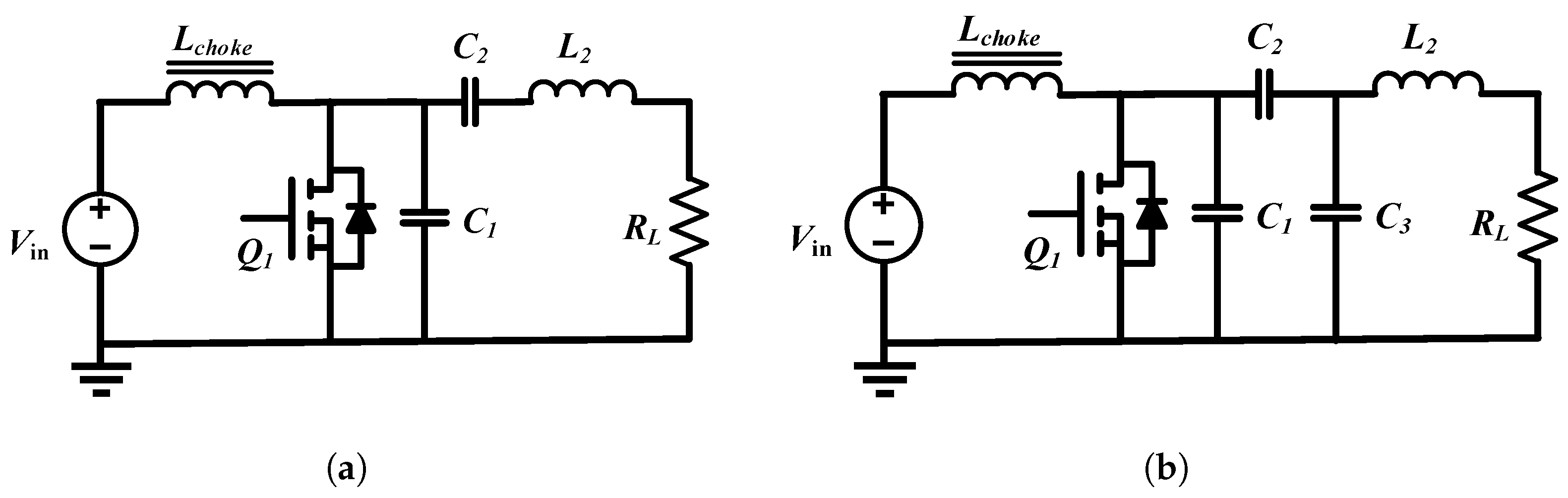
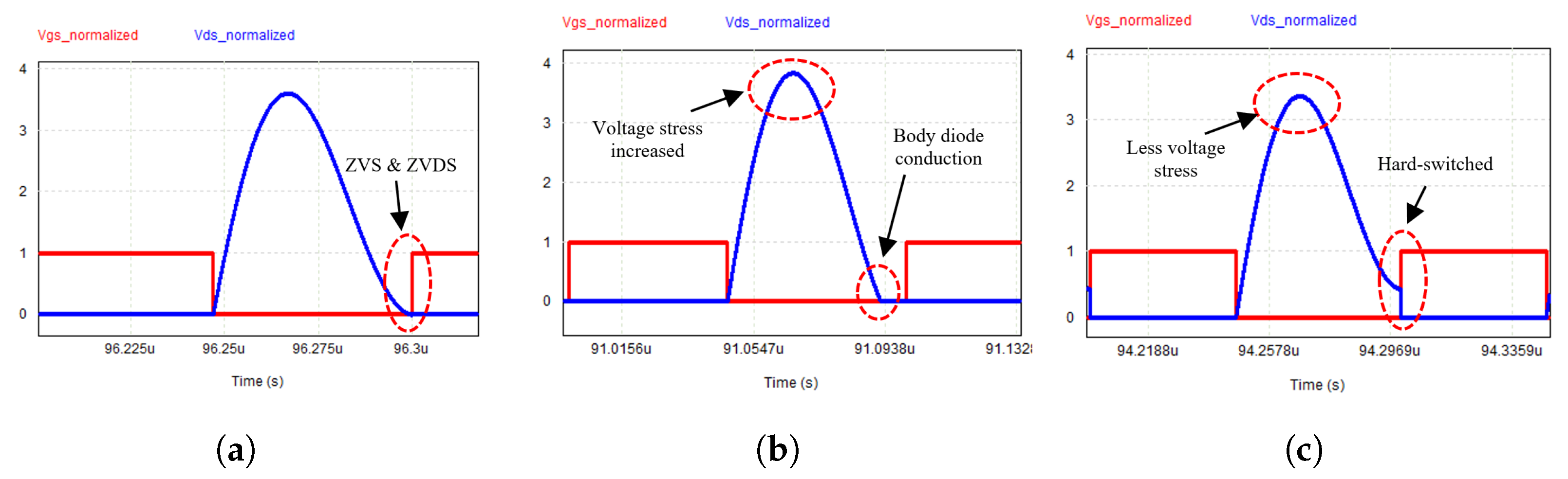
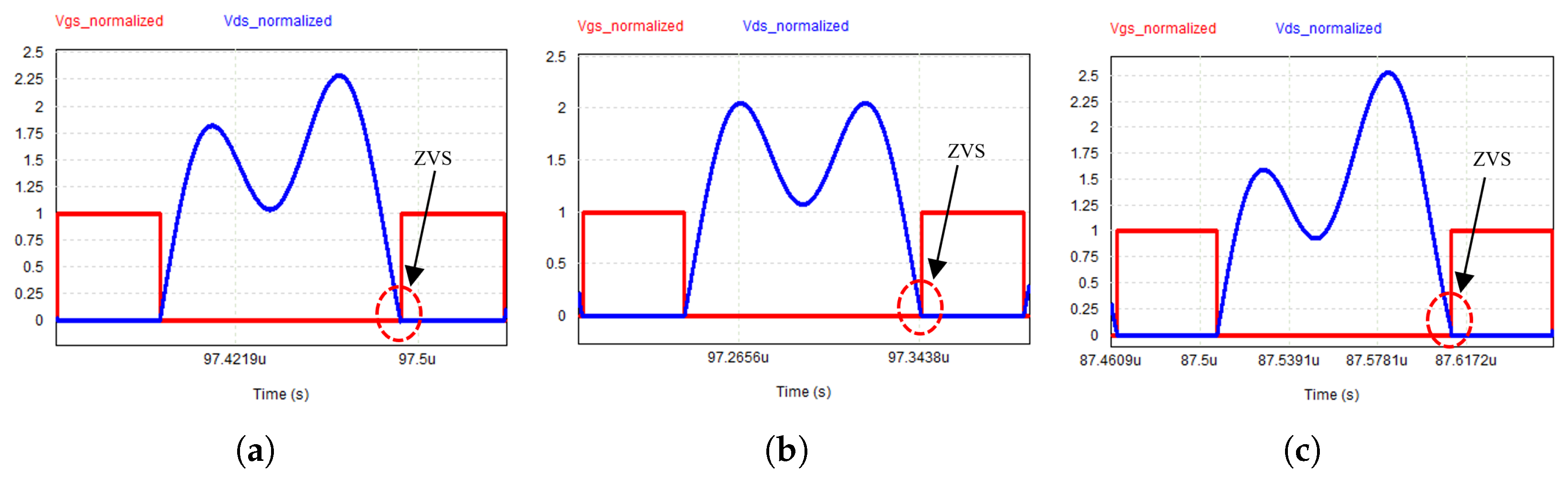
3.1.3. Class EF Topology

The circuit of a Class EF resonant inverter [113] is shown in Figure 13. A resonant branch, L 2 and C 2 , is added across the switch, which offers an extra degree of freedom to the designer to achieve ZVS throughout the entire load range. The extra LC resonant tank also reduces the voltage and current stresses across the switch and improves the efficiency of the inverter as well as increases the power handling capability. The added network can be tuned to twice the switching frequency (or 2nd harmonic), in which case the modified topology is known as the Class EF2 or Class ϕ 2 inverter [114]. This reduces the voltage stress across the switch to 2.31 times the input voltage (compared to 3.56 times for Class E topology). However, tuning the added network to 1.5 times the resonant frequency of the series resonant tank allows a load-independent operation to be achieved [113]. Figure 14 shows the load-independent operation of the Class EF inverter when the added network is tuned to 1.5 times the switching frequency. ZVS is maintained at turn on for values of R L varying from short circuit conditions to two times the nominal value ( R o p t ). Table 5 shows a comparison of Class D, E, and EF resonant inverter topologies.

3.2. Rectifier Topologies

From the time reversal duality [115] concept, rectifier topologies can be derived from inverter topologies and vice versa. For low current applications (<2 A), rectifiers are normally made with diodes, which could lead to significant losses due to hard switching and reverse recovery. Hence, soft-switched (or resonant) topologies which do not have high semiconductor stresses need to be used.

3.2.1. Class D Topology

Figure 15a shows the circuit diagram of a current-driven half-bridge Class D [116] rectifier topology which utilizes two diodes ( D 1 and D 2 ). The input to the system can be modeled as a current source. The positive part of the input current flows through the diode D 2 to the load R d c . The negative part of the input current is circulated back to the source through diode D 1 . C f acts as a DC filter capacitor. A high-frequency square wave voltage is produced across the diodes. This could lead to reverse-recovery losses of the diode in cases where the reverse recovery time is not much lower than the time period of the switching operation. However, despite the potential switching losses, this topology has good semiconductor utilization and high output power capability. During conduction, the diodes are stressed to the input current and while blocking they are stressed to the output voltage. This topology is widely used in low-frequency (50 kHz–1 MHz) WPT systems.

3.2.2. Class E Topology

One issue with using conventional Class D rectifier systems at high frequencies is that the parasitic capacitances of the diodes are voltage dependent and can detune the system. Hence, external capacitors are added parallel to the diodes as part of a resonant circuit so that the losses due to reverse recovery of the diodes are minimized by making the switching a resonant process rather than a hard-switched fast recovery process. This external capacitor is larger than the parasitic capacitance and helps to preserve the tuning of the system through a wider range of power throughput. Figure 15b shows the circuit of a current-driven, low dv/dt, half-bridge Class E rectifier topology [116]. It comprises a capacitor and diode connected in parallel to a second-order filter. The capacitor ( C d ) acts as a voltage snubber. It provides ZVS at turn on and reduces the rate at which the voltage increases during turn off. Since the capacitor and the diode are connected in parallel to the source and the filter, the current flowing through them is the superimposition of the input alternating current and the output constant current. Therefore, when the resonant current is negative, the diode current exceeds it and the conduction losses increase. Furthermore, when the diode is reverse biased, then the peak voltage across it is higher than the output voltage and hence device utilization is poorer than the Class D rectifier. However, because of soft switching, the reverse recovery losses of the diodes are largely eliminated and larger and slower diodes can be used.

3.3. Transmitter Topologies with Constant Current Output

In multiple receiver systems with a voltage-source-type transmitter, the change in load on one receiver affects the amount of power delivery to the others. This is because the power delivery to each receiver is directly proportional to the reflected resistance on the transmitter. The current in the transmitter varies with changes in the reflected resistance with movement or load variations in one receiver, and hence the power transferred to all the receivers can change. Ideally, if the transmitter is a current source and the cross-coupling among the receivers is negligible, the power delivered to each load is only dependent on the impedance reflected to the transmitter. Hence, a decoupled power transfer to the receiver loads can be ensured by using a constant current topology on the transmitter side. A constant current source transmitter transferring power to multiple loads is shown in Figure 16. The current source behavior of the inverter output can be achieved through dynamic control, such as phase shift modulation between the legs of a full-bridge inverter. This removes the need for the addition of an extra impedance-matching circuit, but the dynamic response of the system is much slower and the addition or removal of new devices can lead to damaging transients. To achieve a faster dynamic response, an inherent current source behavior of the inverter is preferred, which can be achieved using passive filters. In [117], the output filter, as shown in Figure 17a, was made using a low pass filter and multiple notch filters, which infers current source characteristics to the full-bridge inverter. The notch filter stage is designed to suppress the low-order harmonics (third, fifth, and seventh), since they can cause higher AC losses and EMI issues. Another impedance matching network (IMN) [118] is shown in Figure 17b. L r and C r as well as L f 1 and C f resonate at the switching frequency. Then, the output current of the transmitter is almost independent of the load resistance reflected to the transmitter, making it behave like a current source. However, other harmonics can impact the performance of the IMN and hence they need to be designed with a high quality factor that can attenuate the harmonics. A high Q network, however, needs a larger inductance, which impacts the size and losses of the IMN. Hence, the IMN must be carefully designed with a trade-off between power density, efficiency, and performance.

4. Coil Design

In Section 2, it has been shown that the maximum efficiency of the WPT link increases with an increase in k 12 2 Q p Q s . Through proper coil design, as will be shown in this section, the coupling coefficient between the transmitter and receiver coils and the quality factor of the coils can be improved to maximize link efficiency.

4.1. Improving Coupling Coefficient between Coils

The coupling coefficient between WPT coils depends on the coil shapes and sizes, the distance and alignment between them, and the type of material used for the conductor. Circular coils are the most common form of WPT coils because of their symmetry and ease of fabrication. The self-inductance of circular spiral coils can be calculated using the circular loop approximation [119]. The mutual inductance between the coils can be calculated by modeling the circular spirals as a set of filamentary circular loops [120]. Other common coil forms include square and rectangular types. Simple expressions for planar spiral inductances (square, hexagonal, octagonal, and circular) have been derived in [121] using a modified Wheeler formula, current sheet approximation, and data fitting. The expressions were found to be accurate within a 5 % error margin. The self-inductance of the coil required for a particular application also determines its size. Some applications also have geometric constraints that the coils must adhere to. For example, the receiver coil size in phones and wearables depends on the space available inside the enclosure. The coupling coefficient between coils can be measured using a two-port network analyzer.
One important criterion which affects the coupling coefficient between the coils is the misalignment between them. The common types of misalignments that occur are lateral (or horizontal), angular, and vertical. Misalignment between coils can drastically reduce coupling among the coils and reduce the efficiency and power transfer capability of the system [88]. Hence, there is a need to develop more misalignment-tolerant systems which can provide more spatial freedom to the receiver coil. A few methods to achieve more tolerance for misalignment are:
1.
Increasing the size of the conventional transmitter.
2.
Using multiple transmitter coils [85] (or coil arrays).
3.
Geometric optimization of the position of each turn of the coil [122].
4.
Specialized design of transmitter coils with an interleaved structure [123].
While using a large transmitter coil requires fewer design challenges, the magnetic field produced by the transmitter is not uniform and much of the flux produced by the transmitter coil remains uncoupled with the receiving coils. Hence, this reduces the efficiency and drives up the cost of the system while also requiring a larger area for the coil. Multiple transmitter coils can shape the overall magnetic field to be more uniform over the entire transmitter surface by forming three orthogonal H-field components [124]. However, this requires six separate transmitter coils to generate two lateral ( H x and H y ) and one axial ( H z ) H-field component, which requires a large space and increases the cost. Some transmitter arrays track the receiver position and power of only the nearby coils. However, individual coil current control complicates the system design because of sensing and tracking circuitry. In [122], the radius of each of the turns of the coil was optimized to create a nearly uniform magnetic field above the transmitter coil. However, many coil turns are required to achieve a uniform magnetic field using conventional coil structures [123]. In applications covering a large charging area, a large number of turns leads to a large inductance. For application in ISM band frequencies (6.78 MHz or 13.56 MHz), large inductances make the coil more sensitive to parasitics. Another issue with using many turns is that the length of the coil can approach the quarter wavelength at 6.78 MHz, causing significant radiation loss. In [123], parallel windings were used to improve the uniformity of the magnetic field across the transmitter surface without needing a high number of turns. To equally distribute the current through each turn, they were swapped at the halfway point so that they had equal length and impedance. Series compensator capacitors were also distributed in many places over the length of the interleaved coil. These distributed capacitors reduced the voltage drop across the coil and thereby the electric field generated across it. This electric field can cause dielectric losses in the material that the transmitter coil is mounted within. Figure 18a shows the proposed coil structure in [123] with discrete compensation capacitors, and Figure 18b shows the measurement of the magnetic field strength at a test receiver coil (10 cm diameter) at a height of 1.8 cm from a transmitter coil of 50 cm diameter.

4.2. Improving the Quality Factor of Coils

The quality factor of the coil can be improved by reducing the AC resistance of the windings. Based on the operating frequency, the winding conductor can be solid, foil, tubular, or Litz. High-frequency eddy currents induced in a current-carrying conductor at high frequencies can cause conduction losses. Eddy currents can be induced by time-varying magnetic fields. At high frequencies, currents mostly flow near the surface of the conductors (depending on the skin depth at that frequency), leaving the inner part with almost zero current flow. This phenomenon increases the AC resistance of the conductor and is called the skin effect. When the radius of the conductor is smaller than the skin depth, current flows uniformly through the cross-section of the wire. The flow of current in close-by conductors often restricts the distribution of currents in the wires of the coils to smaller regions. This phenomenon is called the proximity effect and it increases the effective resistance of the coils, which increases with frequency. Tightly wound coils with a very low pitch between the turns have a low quality factor due to the prominence of proximity losses. Foil wires are widely used in inductive WPT systems. Copper foils with a thickness close to skin depth in the MHz frequency range (copper skin depth is between 65 and 15 µm in the 1–20 MHz range) are commercially available. They can also be manufactured in printed circuit boards (PCBs). Another advantage of using a foil conductor is the high current carrying capacity due to the large surface area and better thermal performance. Tubular coils wi multiple insulated concentric tubular conductors are often used for optimum current flow to reduce AC resistance. In [125], magneto-plated wires were used to reduce the AC resistance of coils by using a magnetic thin film for plating the copper wire’s circumference.
A popular technique to reduce the AC resistance of wires is by using Litz wires, which are made of multiple strands of thin copper wire twisted in a bundle. To minimize losses due to the skin effect, the width of each strand is less than the skin depth of copper at that frequency. The twisting of the bundles of the wire in a helical fashion prevents proximity effect losses and ensures that each strand carries the same current. The RMS current carrying capability of the wire determines the number of strands. However, commercial Litz wires are beneficial for frequencies up to a few MHz, since at ISM frequencies of 6.78 MHz or 13.56 MHz, very thin wires are required, which can be very expensive and have poor tensile strength. Furthermore, since they are not available commercially, special manufacturing is required, which increases the cost. Litz wires are more attractive in the hundreds of kHz range up to a few MHz; however, a solid core copper wire is preferred for ISM MHz frequencies.
At low frequencies, when the diameter of the wire is less than the skin depth, the copper wire has a constant DC resistance. At higher frequencies, when the diameter of the wire is much more than the skin depth, the AC resistance of the wire increases approximately as the square root of the frequency until radiation effects start to become dominant. At very high frequencies (typically above a few tens of MHz), the length of the wire is comparable to the wavelength of the operating frequency and the coil acts like an antenna and starts to radiate. At those frequencies, the AC resistance approximately increases as the fourth power of frequency. Hence, the quality factor of the coils starts to decrease with an increase in frequency once they start to radiate power.

4.3. Self-Resonant Coils

Series compensation of coils is most widely used for WPT. When designing high Q systems, the resonant voltage may be very high across the capacitors which may lead to a breakdown of discrete commercially available capacitors. One method to reduce the voltage stresses is by using large arrays of capacitors. However, this increases the cost and reduces the power density of the system. Furthermore, it introduces stray impedances, especially for high Q coils when the capacitance required is in the low pF range. Another approach is to use the self-resonance of the coil, where the intrinsic electric field of the coil resonates with the magnetic field. The analysis and design of a series self-resonant coil has been demonstrated in [126], where two identical planar coils were separated by a layer of dielectric material. One terminal of each coil is connected to the AC source while the other terminals are left open. To reduce the copper resistance, the copper width can be increased. However, for a two-layer coil, the width of the copper also determines the interlayer resonant capacitance. Furthermore, to achieve the designed inductance value, the coils need to have a specific number of turns that need to be fit within the desired diameter. Hence, it can be seen that the self-resonant structure of the two-layer coil inherently restricts the achievable quality factor. This can be remedied by using a multi-layer coil in which current sharing can take place across multiple layers. A multi-layer, non-uniform, self-resonant coil was proposed in [127]. This multi-layer structure gives added freedom to obtain the required capacitance from the coil.

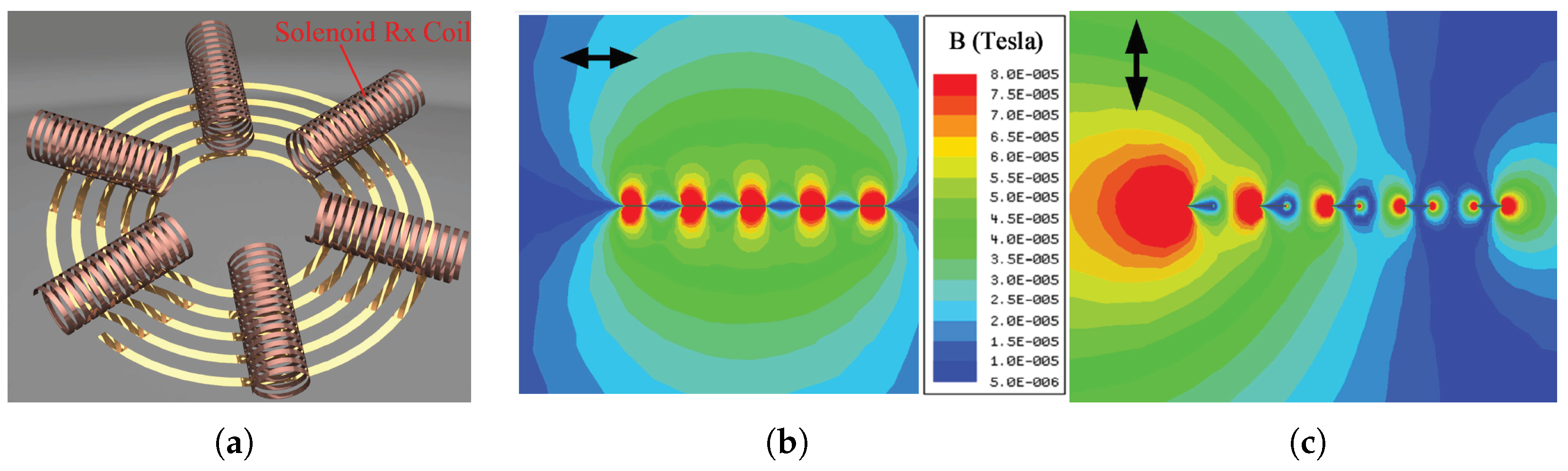
4.4. Omnidirectional Wireless Power Transfer

Planar transmitter coils produce magnetic fields in a fixed direction. Hence, the movement of the receiver coil from its desired location can reduce the flux linkage with the transmitter coil and diminish the power transferred to the load. To expand the positional freedom of wireless power transfer, omnidirectional wireless charging has been gaining a lot of interest over the past few years [128,129,130,131,132,133,134,135,136]. Based on the number of sources used for the transmitter, omnidirectional WPT systems can be classified into two types:
  • Multiple power sources used for multiple transmitter coils. Based on the location of the receiver, the amplitude and phase of the coil currents are controlled dynamically. This requires complicated external control circuits for measurements and feedback and can become expensive in practice.
  • A single power source is connected to the transmitter. This technique is simpler to implement. However, the system can have blind spots where the coupling is much less.
Hence, it is essential to find solutions for truly omnidirectional WPT systems which do not require excessively complicated active control of the transmitter coils. Based on the direction of the magnetic field produced, omnidirectional WPT systems can be broadly classified into two-dimensional and three-dimensional systems.

4.4.1. Two-Dimensional Omnidirectional Wireless Power Transfer

A 2D WPT system for unmanned aerial vehicles has been proposed in [128]. The system uses two orthogonal coils that produce an omnidirectional magnetic field that can charge a rotating load. The system maximizes power transfer using an extremum-seeking control technique. The control system uses the input power as the objective function by analyzing its response to load mobility. The technique also does not require any feedback from the receiver. Cylindrical coaxial WPT coils were used for 2D omnidirectional applications in [129]. The receiver coils had the freedom to have any angular position; however, their linear motion was restricted only in the vertical direction. Ref. [130] proposed a cylindrical transmitter coil that is capable of transmitting power in two dimensions by creating a planar homogeneous magnetic field. A helical winding structure with two coils was used for the transmitter and the setup could produce true 2D WPT without any blind spots. A promising feature of this system is the use of a single power source that feeds the transmitter coil. The system also does not require any active control of the amplitude or phase of the power source. Ref. [131] showed that for a 2D omnidirectional WPT system, the net input power and the system efficiency are sinusoidal functions of the angle of the input magnetic field vector and their maximum values are independent of the load and operating frequencies. Once the load direction is detected, an optimized driving strategy can be chosen.

4.4.2. Three-Dimensional Omnidirectional Wireless Power Transfer

Three-dimensional transmitter coil structures, as shown in Figure 19a, can produce orthogonal currents, the vectorial summation of which can produce a net magnetic field in any direction [132]. The magnitude of this magnetic field can be controlled using amplitude modulation of the current, phase angle control, or modulation of frequency. The amplitude modulation technique can be implemented by keeping the current magnitude of one of the transmitter coils constant while modulating the amplitude of the other two coils with two sinusoidal envelopes [133]. These envelopes are shifted in phase by 90 degrees. The magnetic field trajectory produced by these currents rotates periodically in all directions, generating an omnidirectional field. The phase angle control technique can be implemented by using the same current amplitude for each of the three coils but controlling the phase shift between each of them.
Ref. [134] proved that by using three orthogonal coils, an omnidirectional magnetic field distribution is produced only near the center of the structure. Near the surface of the sphere, the magnetic field is not omnidirectional. Hence, Refs. [134,135] proposed a bowl-shaped structure for the transmitter. Ref. [134] pointed out that near the side face of the bowl, it is preferable to have a magnetic field perpendicular to the surface, and near the bottom, an omnidirectional field distribution is preferable. To achieve this, the authors used a five-coil structure, with four coils wound from the bottom to the side face of the bowl and one coil placed around the bottom face. A pareto optimization technique was used to achieve uniform field distribution. Ref. [136] demonstrated that when a circular receiver coil is used with a three-dimensional transmitter structure, the performance of the system can deteriorate with the self-rotation of the receiver coil. Hence, the authors proposed a quadrature-shaped receiver coil, as shown in Figure 19b, to improve the transmitted power even when there is angular misalignment.

4.5. Use of Ferrite Cores

Using soft magnetic materials such as ferrite cores is one method of increasing the coupling coefficient among the coils. The high permeability of the ferrite core can be used to shape the field produced between the coils and increase the coupling between them. Ferrites also increase the self-inductance of the coils. Ferrite materials, which have high saturation flux density, high bulk resistivity, high permeability, and low AC power losses, are beneficial for WPT systems. NiZn and MnZn are the most commonly used ferrites in WPT. MnZn has a high saturation flux density and a high permeability, while NiZn ferrite has a lower permeability and a high bulk resistivity. A ferrite with high permeability increases the magnetic energy storage per unit self-inductance of the coil. A ferrite with high bulk resistivity reduces the high-frequency-induced eddy and displacement currents. The core loss in ferrites for sinusoidal excitation depends on the frequency and magnetic flux density in the core. Hence, ferrites are popular in frequency ranges below the MHz range. Coils operating in the ISM band use air core coils because the core losses due to ferrites are high at these frequencies. Ferrites also help to shield the magnetic field produced by the coils and reduce the EMI. Figure 20b shows the magnetic field distribution with MnZn ferrite shielding [137].

4.6. Solenoidal Receiver Coils for Multiple Receiver Systems

Spiral receiver coils placed face down on the transmitter pad lead to poor utilization of the transmitter area because of the increased surface area required for the receivers. A spiral or double-D transmitter coil can be used with solenoidal receiver coils to increase the arrangement density of the receivers [138]. Figure 21a shows a spiral transmitter coil with solenoidal receiver coils. Solenoidal receiver coils use the radial component of the magnetic field generated by the transmitter coil, and spiral receiver coils use the axial component. As shown in Figure 21b,c, the radial magnetic flux density of the spiral transmitter coil has better homogeneity than the axial component. Hence, the coupling between the transmitter and receiver coils is less sensitive to misalignment with the solenoidal receiver coils. Furthermore, if the spacing between the traces of the transmitter coil is high, the magnetic flux density of the radial component is higher than the axial one. Ferrite sheets can be used inside the receiver coils, which causes a greater gain in the magnetic field parallel to it and hence the coupling between transmitter and receiver coils is increased.

5. Foreign Object Detection

Foreign objects kept near the AC magnetic flux generated by the WPT coils can absorb power if they are of metallic or ferromagnetic nature. Induced eddy currents circulate within the materials, resulting in a conduction loss and a temperature rise. These currents increase the temperature of the foreign material and could become a potential safety concern. Foreign objects can be “friendly” or “unwanted”. Friendly foreign objects are generally parts of the charging devices that may absorb some power. Unwanted objects are external ones that are not part of the device, such as coins, keys, ornaments, utensils, etc. Some types of foreign object detection methods are given below [85]:
1.
Power difference method—The transmitted and received power are monitored. If the difference between them is higher than a set threshold, it indicates the presence of foreign objects. In this case, the transmitter stops delivering power to the receiver circuit.
2.
Sensor method—Temperature and/or metal sensors are used to detect any anomaly in the transmission path. Anomalies detected by the sensors are communicated to the transmitter using load modulation. If the temperature sensed is higher than the threshold or there are metals present in the transmission path, the control circuit will shut down the power transmission.
3.
Transient energy decay method—The transmitter is powered for a short time and then disabled to check the rate of transient energy decay. If this rate exceeds the set threshold, the presence of a foreign object is confirmed and the system is shut down.

6. EMC/EMI Issues and EMF Safety in Near-Field Wireless Power Transfer

A near-field WPT system produces a certain level of EMI (electromagnetic interference) that can adversely affect the performance of nearby electrical/electronic equipment by radiated and conducted emission. In WPT systems, common mode noise is the main source of EMI issues, which is difficult to eliminate. Symmetrical and perfectly differential construction of transmitters and receivers can somewhat mitigate this issue. Besides the transmitter, the rectifier in the receiver is the highest source of harmonics. The discontinuities caused by the sharp transitions in the rectifier are coupled directly to the coils, which radiate this as high-frequency noise. To minimize the harmonics, notch/bandpass harmonic filters can be used with the rectifiers.
WPT systems are not yet fully standardized for EMC (electromagnetic compatibility) and EMI, and the process is ongoing. The main international standardization bodies are ITU-R (International Telecommunication Union-Radiocommunication sector), IEC (International Electrotechnical Commission), CISPR (Comité International Spécial des Perturbations Radioélectriques), ETSI (European Telecommunications Standards Institute), CEPT (European Conference of Postal and Telecommunications Administrations), FCC (Federal Communications Commission: Part-15 and Part-18), and some other national bodies.

6.1. De-Sense Caused by In-Band Noise and Shielding in Smartphones

Every smartphone must satisfy some receiver sensitivity criteria (wireless WAN antenna sensitivity) to be approved by the FCC. The EMI noise produced by the system must be reduced at the antennae to maintain an appropriate signal-to-noise ratio. Furthermore, any shielding near the antennae can cause a degradation in sensitivity (de-sense). At low frequencies (near 110–205 kHz), ferrites used as shields reduce the receiver sensitivity by about 12 dB. This could worsen cell reception in low-signal areas. Requirements regarding de-sense are much harder to meet than EMI compatibility [139]. These are easier to meet at high frequencies because  6.78  MHz antennae cause a sensitivity reduction of only 2dB.

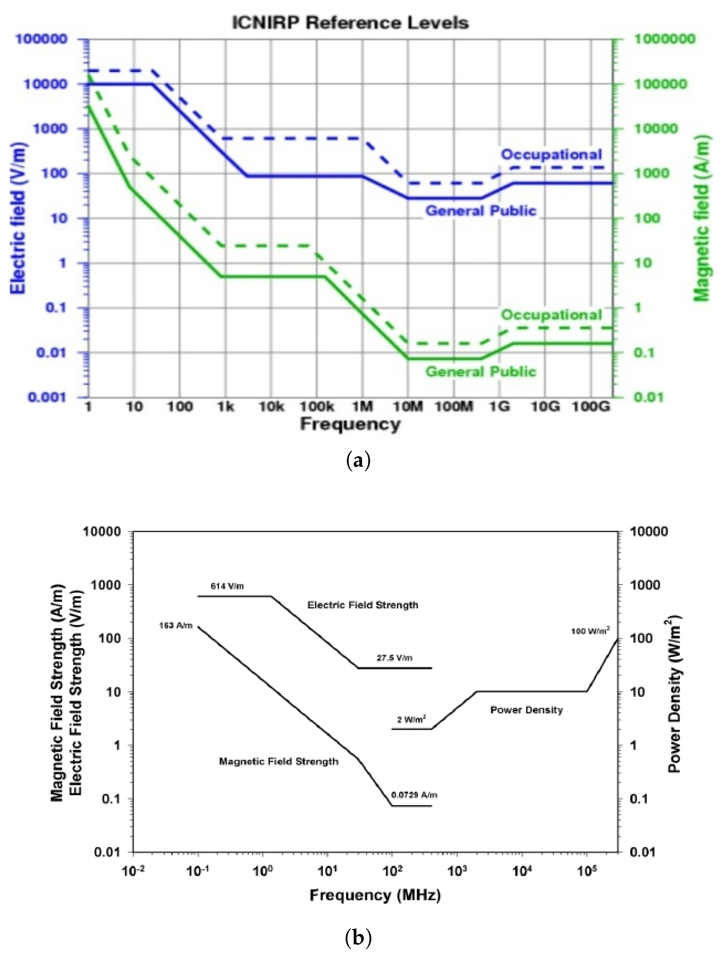
6.2. EMF Safety Standards

The currents in the WPT coils produce significant magnetic fields (H-field), electric fields (E-field), and electromagnetic fields (EMF) in the environment that can induce adverse health effects in the human body. Therefore, ensuring that WPT systems remain within the safety limits for human exposure is very important. Some of the existing international standards for safety from EMF exposure are:
1.
International Commission on Non-Ionizing Radiation Protection (ICNIRP) Guidelines for Limiting Exposure to Time-varying E-field, H-field, and EMF (up to 300 GHz) [140].
2.
IEEE Standard for Safety Levels with Respect to Human Exposure to Radio Frequency EMF (3 kHz to 300 GHz) [141].
Both organizations set standards on safe magnetic and electric field levels for human exposure as a function of frequency. Figure 22a shows the typical human exposure limits established by the ICNIRP, which cover occupational exposure and general public exposure. In the frequency range of of 1 MHz to 10 MHz, the general public reference level for an E-field is 87/ f 1 / 2 V/m and for an H-field it is 0.73/f A/m. In the frequency range of 10 to 400 MHz, the general public reference levels for an E-field is 28 V/m and for an H-field, it is 0.073 A/m. Figure 22b presents IEEE guidelines for exposure to time-varying electric and magnetic fields. As shown in the figure, as the operating frequency increases, the maximum electric and magnetic field levels decrease. In the frequency range 0.1 to 1.34 MHz, the maximum permissible exposure (MPE) for an RMS E-field is 614 V/m and for an RMS H-field, it is 16.3/f A/m. In the frequency range of 1.34 to 30 MHz, th MPE for an RMS E-field is 823.8/f V/m and for an RMS H-field, it is 158.3 / f 1.668 A/m.
Another restriction on exposure to EMF fields is the specific absorption rate (SAR). This is the rate at which the human body absorbs energy when exposed to radiofrequency electromagnetic fields. The SAR is proportional to the square of the E-field in human tissues and is dependent on the following:
1.
Frequency, intensity, and polarization of the EMF.
2.
Type of EMF source (near-field or far-field).
3.
Size, the internal and external geometry of the exposed body part, and the dielectric properties of various tissues.
4.
Reflection effects of the field from objects in the vicinity of the exposed body.
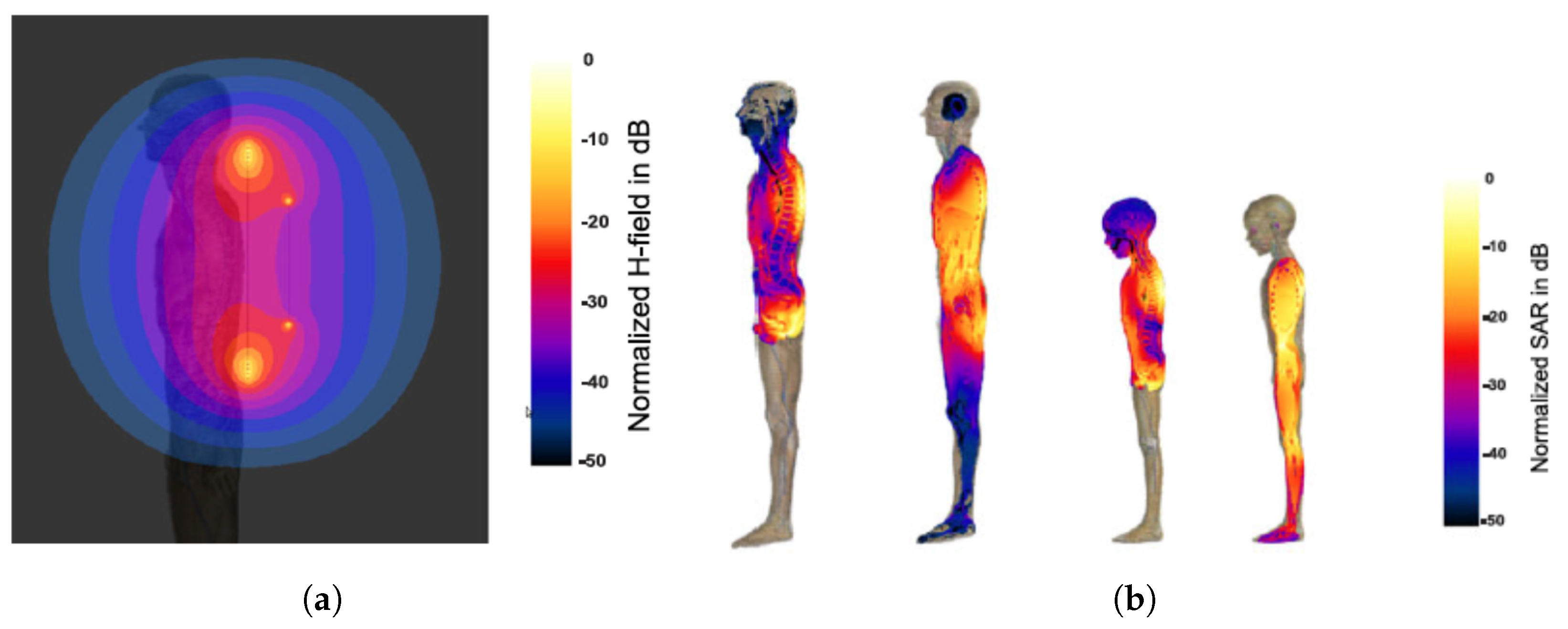
Therefore, the SAR limits RF energy absorption in the whole body to prevent thermal stress and local injuries. Ref. [143] presents the absorption of energy in the human body based on the frequency ranges as shown below:
1.
Between 100 kHz and 20 MHz: with decreasing frequency, absorption reduces rapidly in the trunk, and significant absorption may happen in the neck and legs.
2.
Between 20 kHz and 300 MHz: absorption over the whole body is high, and if partial resonances are considered, then it is even higher.
3.
Between 300 MHz and 10 GHz: significant non-uniform, local absorption occurs.
4.
Above 10 GHz: absorption occurs primarily at the surface of the body.
Table 6 shows the exposure guidelines which demonstrate the SAR exposure limit in watts per kilogram.

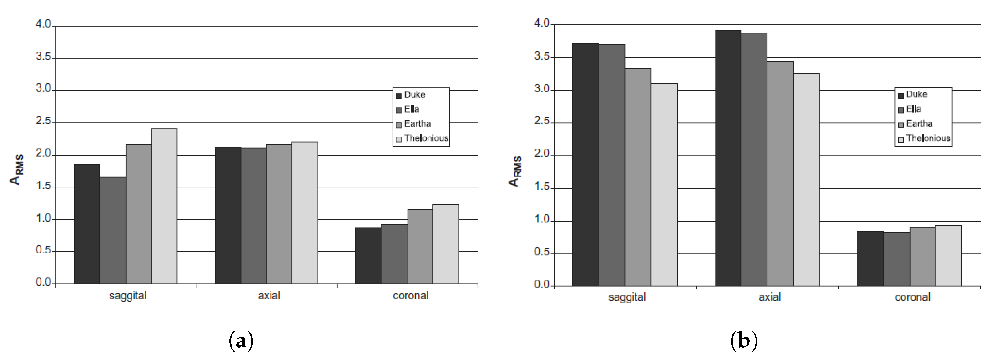
6.3. Studies on EMF Safety

EMF exposure limits in humans from wireless power were evaluated by using numerical analyses and measurements in [144]. MHz WPT systems via near-field coupling over a few meters distances were examined based on SAR levels. Four different anatomical models were used (two adults, Duke and Ella, and two children, Eartha and Thelonious) and exposed to a WPT transmitter operating at 8 MHz along the coronal, axial, and sagittal orientations. The models did not distort the H-field in the simulation; however, the resonant frequency of the coils was decreased from 8 MHz to 7.6 MHz. Figure 23a shows the distribution of the H-field near one of the anatomical models. Figure 23b shows local SAR distributions in two anatomical models. The most restrictive limit occurs with coronal exposure because the largest area of the body is exposed to the coil. With the coronal orientation, the exposure limits of 0.5–1.2 A RMS were reached depending on the body models and SAR limits. In the work, the 1 g average SAR limit from IEEE C95.1-1999 and the 10 g average SAR limit from ICNIRP and IEEE C95.1-2005 were used. Figure 24 shows the current in the transmitting coil when the SAR values reached the IEEE and ICNIRP safety thresholds. The paper shows that a 0.5 A RMS corresponded to a 45 W transmitting power and a 1.2 A RMS corresponded to a 280 W transmitting power. These results provide the reference current and power limits at which the SAR values reach safety thresholds.

7. Conclusions

This paper serves as a basis for engineers by summarizing all relevant aspects of wireless power system design for applications in portable electronics. Firstly, IPT was compared with CPT and their advantages and shortcomings were highlighted. While CPT offers some benefits in terms of misalignment tolerance and non-requirement of ferrites, IPT is preferred in the industry today for portable electronics applications for a variety of reasons, as pointed out in the paper. The efficiency of WPT systems can be increased by operating the transmitter and receiver coils at resonance and by optimizing the load resistances experienced by the receivers. Techniques to mitigate the effect of cross-coupling with multiple receivers and improving the system efficiency in their presence are noted as promising research areas.
High-frequency operation of WPT systems leads to miniaturization of the components and a higher efficiency. For this reason, various soft-switched topologies such as Class D, E, EF, etc., are used to operate the WPT systems at high frequencies in the megahertz range. WBG and ultra-WBG devices can be used for very high frequency operation. Compensation topologies reduce the VA rating of the transmitter and can also infer voltage source or constant source characteristics to the inverters. Constant current source inverters are particularly useful when using multiple receivers since they ensure decoupled power transfer to the receivers.
Coil design is an integral part of a WPT system since a proper design can optimize the k-Q product of the system and increase the link efficiency. The k-Q product can be improved by increasing the coupling between the transmitting and receiving coils and by improving the quality factor of the coils. WPT coils are intentional sources of EMI, and hence EMF safety becomes an issue of concern. EMF safety limits have not been fully standardized, and only the acute (short-term) effects have been examined. More research is needed to understand the long-term effects of such field exposures.
WPT is an exciting multi-disciplinary research area and the future looks very promising. The authors believe that with advances in semiconductor technologies taking switching frequencies into the range of several tens or hundreds of mega-hertz, wireless power transfer technologies will soon overtake their wired counterparts for charging portable electronics. Wireless charging has the advantage of charging multiple devices simultaneously without the wasteful use of wires. It will revolutionize the medical, robotics, and electronics industries by reducing the dependence on battery capacity and human interaction for charging. Further improvements in control techniques, coil design, topologies, etc., will take wireless power transfer to new heights and continue its widespread commercialization.

Author Contributions

Conceptualization, A.L., M.P. and P.J.; methodology, A.L., A.K. and M.P.; writing—original draft preparation, A.L.; writing—review and editing, A.K., M.P. and P.J. All authors have read and agreed to the published version of the manuscript.

Funding

This research received no external funding.

Data Availability Statement

Not applicable.

Conflicts of Interest

The authors declare no conflict of interest.

References

  1. Nikola Tesla 1857–1943. Proc. IRE 1943, 31, 194–1943. [CrossRef]
  2. Tesla, N. High frequency oscillators for electro-therapeutic and other purposes. Proc. IEEE 1999, 87, 1282. [Google Scholar] [CrossRef]
  3. Garnica, J.; Chinga, R.A.; Lin, J. Wireless Power Transmission: From Far Field to Near Field. Proc. IEEE 2013, 101, 1321–1331. [Google Scholar] [CrossRef]
  4. Litz Wire. Available online: https://mwswire.com/specialty-wire/litz-wire/ (accessed on 12 January 2023).
  5. Ghahary, A.; Cho, B.H. Design of a transcutaneous energy transmission system using a series resonant converter. In Proceedings of the 21st Annual IEEE Conference on Power Electronics Specialists, San Antonio, TX, USA, 11–14 June 1990; pp. 1–8. [Google Scholar] [CrossRef]
  6. Joun, G.B.; Cho, B.H. An energy transmission system for an artificial heart using leakage inductance compensation of transcutaneous transformer. IEEE Trans. Power Electron. 1998, 13, 1013–1022. [Google Scholar] [CrossRef]
  7. Elliott, G.A.J.; Boys, J.T.; Green, A.W. Magnetically coupled systems for power transfer to electric vehicles. In Proceedings of the 1995 International Conference on Power Electronics and Drive Systems. PEDS 95, Singapore, 21–24 February 1995; Volume 2, pp. 797–801. [Google Scholar] [CrossRef]
  8. Green, A.W.; Boys, J.T. 10 kHz inductively coupled power transfer-concept and control. In Proceedings of the Fifth International Conference on Power Electronics and Variable-Speed Drives, London, UK, 26–28 October 1994; pp. 694–699. [Google Scholar] [CrossRef]
  9. Hui, S.Y.R. Planar Inductive Battery Charger. UK Patent GB2389720B, 7 September 2005. [Google Scholar]
  10. Kim, C.G.; Seo, D.H.; You, J.S.; Park, J.H.; Cho, B.H. Design of a contactless battery charger for cellular phone. In Proceedings of the Fifteenth Annual IEEE Applied Power Electronics Conference and Exposition (Cat. No.00CH37058), New Orleans, LA, USA, 6–10 February 2000; Volume 2, pp. 769–773. [Google Scholar] [CrossRef]
  11. Jang, Y.; Jovanovic, M.M. A contactless electrical energy transmission system for portable-telephone battery chargers. IEEE Trans. Ind. Electron. 2003, 50, 520–527. [Google Scholar] [CrossRef] [Green Version]
  12. Wong, C.S.; Duzgoren-Aydin, N.S.; Aydin, A.; Wong, M.H. Evidence of excessive releases of metals from primitive e-waste processing in Guiyu, China. Environ Pollut. 2007, 148, 62–72. [Google Scholar] [CrossRef]
  13. Hutin, M.; LeBlanc, M. Transformer Systems for Electric Railways. U.S. Patent US527857A, 23 October 1894. [Google Scholar]
  14. Schuder, J.C.; Stephenson, H.E.; Townsend, J.F. High level electromagnetic energy transfer through a closed chestwall. IRE Int. Conv. Rec. 1961, 9, 119–126. [Google Scholar]
  15. Brown, W.C. The history of wireless power transmission. Solar Energy 1996, 56, 3–21. [Google Scholar] [CrossRef]
  16. Niu, S.; Xu, H.; Sun, Z.; Shao, Z.Y.; Jian, L. The state-of-the-arts of wireless electric vehicle charging via magnetic resonance: Principles, standards and core technologies. Renew. Sustain. Energy Rev. 2019, 114, 109302. [Google Scholar] [CrossRef]
  17. Brown, W.C.; Triner, J.F. Experimental Thin-Film, Etched-Circuit Rectenna. In Proceedings of the IEEE MTT-S International Microwave Symposium Digest, Dallas, TX, USA, 15–17 June 1982; pp. 185–187. [Google Scholar] [CrossRef]
  18. Wang, C.S.; Stielau, O.H.; Covic, G.A. Design considerations for a contactless electric vehicle battery charger. IEEE Trans. Ind. Electron. 2005, 52, 1308–1314. [Google Scholar] [CrossRef]
  19. Kurs, A.; Moffatt, R.; Soljacic, M. Simultaneous mid-range power transfer to multiple devices. Appl. Phys. Lett. 2010, 96, 044102-1–044102-3. [Google Scholar] [CrossRef]
  20. Lee, S.; Huh, J.; Park, C.; Choi, N.S.; ChoG, H.; Rim, C.T. On-Line Electric Vehicle using inductive power transfer system. In Proceedings of the IEEE Energy Conversion Congress and Exposition, Atlanta, GA, USA, 12–16 September 2010; pp. 1598–1601. [Google Scholar] [CrossRef]
  21. Sample, A.P.; Yeager, D.J.; Powledge, P.S.; Mamishev, A.V.; Smith, J.R. Design of an RFID-Based Battery-Free Programmable Sensing Platform. IEEE Trans. Instrum. Meas. 2008, 57, 2608–2615. [Google Scholar] [CrossRef]
  22. Ullah, M.A.; Keshavarz, R.; Abolhasan, M.; Lipman, J.; Esselle, K.P.; Shariati, N. A Review on Antenna Technologies for Ambient RF Energy Harvesting and Wireless Power Transfer: Designs, Challenges and Applications. IEEE Access 2022, 10, 17231–17267. [Google Scholar] [CrossRef]
  23. Ishino, S.; Takano, I.; Yano, K.; Shinohara, N. Frequency-division techniques for microwave power transfer and wireless communication system with closed waveguide. In Proceedings of the 2016 IEEE Wireless Power Transfer Conference (WPTC), Aveiro, Portugal, 5–6 May 2016; pp. 1–4. [Google Scholar] [CrossRef]
  24. Putra, A.W.S.; Kato, H.; Maruyama, T. Hybrid Optical Wireless Power and Data Transmission System. In Proceedings of the IEEE PELS Workshop on Emerging Technologies: Wireless Power Transfer (WoW), Seoul, Republic of Korea, 15–19 November 2020; pp. 374–376. [Google Scholar] [CrossRef]
  25. So, E.; Yeon, P.; Chichilnisky, E.J.; Arbabian, A. An RF-Ultrasound Relay for Adaptive Wireless Powering Across Tissue Interfaces. IEEE J. Solid-State Circuits 2022, 57, 3429–3441. [Google Scholar] [CrossRef]
  26. Chang, C.K.; Da Silva, G.G.; Kumar, A.; Pervaiz, S.; Afridi, K.K. 30 W capacitive wireless power transfer system with 5.8 pF coupling capacitance. In Proceedings of the IEEE Wireless Power Transfer Conference (WPTC), Boulder, CO, USA, 13–15 May 2015; pp. 1–4. [Google Scholar] [CrossRef]
  27. Kim, M.; Choi, J. Design of High-frequency Resonant Inverter for Capacitive Wireless Power Transfer. In Proceedings of the IEEE 21st Workshop on Control and Modeling for Power Electronics (COMPEL), Aalborg, Denmark, 9–12 November 2020; pp. 1–7. [Google Scholar] [CrossRef]
  28. Kumar, A.; Pervaiz, S.; Chang, C.K.; Korhummel, S.; Popovic, Z.; Afridi, K.K. Investigation of power transfer density enhancement in large air-gap capacitive wireless power transfer systems. In Proceedings of the IEEE Wireless Power Transfer Conference (WPTC), 13–15 May 2015; pp. 1–4. [Google Scholar] [CrossRef]
  29. Rose, J.A.; Cates, J.A. Capacitive Charge Coupling with Dual Connector Assemblies and Charging System. U.S. Patent 5 714 864, 3 February 1998. [Google Scholar]
  30. Liu, C.; Hu, A.P. Steady state analysis of a capacitively coupled contactless power transfer system. In Proceedings of the IEEE Energy Conversion Congress and Exposition, San Jose, CA, USA, 20–24 September 2009; pp. 3233–3238. [Google Scholar] [CrossRef]
  31. Wahab, A.; Chong, T.E.; Min, L.K. Wireless pointing device using capacitive coupling. In Proceedings of the 1997 IEEE International Symposium on Consumer Electronics (Cat. No.97TH8348), Singapore, 2–4 December 1997; pp. 149–152. [Google Scholar] [CrossRef]
  32. Kline, M.; Izyumin, I.; Boser, B.; Sanders, S. Capacitive power transfer for contactless charging. In Proceedings of the Twenty-Sixth Annual IEEE Applied Power Electronics Conference and Exposition (APEC), Fort Worth, TX, USA, 6–11 March 2011; pp. 1398–1404. [Google Scholar] [CrossRef] [Green Version]
  33. Choi, J.; Tsukiyama, D.; Rivas, J. Comparison of SiC and eGaN devices in a 6.78 MHz 2.2 kW resonant inverter for wireless power transfer. In Proceedings of the IEEE Energy Conversion Congress and Exposition (ECCE), Milwaukee, WI, USA, 18–22 September 2016; pp. 1–6. [Google Scholar] [CrossRef]
  34. Stevanovic, L.D.; Matocha, K.S.; Losee, P.A.; Glaser, J.S.; Nasadoski, J.J.; Arthur, S.D. Recent advances in silicon carbide MOSFET power devices. In Proceedings of the Twenty-Fifth Annual IEEE Applied Power Electronics Conference and Exposition (APEC), Palm Springs, CA, USA, 21–25 February 2010; pp. 401–407. [Google Scholar] [CrossRef]
  35. Pandey, P.; Nelson, T.M.; Collings, W.M.; Hontz, M.R.; Georgiev, D.G.; Koehler, A.D.; Anderson, T.J.; Gallagher, J.C.; Foster, G.M.; Jacobs, A.; et al. A Simple Edge Termination Design for Vertical GaN P-N Diodes. IEEE Trans. Electron Devices 2022, 69, 5096–5103. [Google Scholar] [CrossRef]
  36. Choi, B.; Nho, J.; Cha, H.; Ahn, T.; Choi, S. Design and implementation of low-profile contactless battery charger using planar printed circuit board windings as energy transfer device. IEEE Trans. Ind. Electron. 2004, 51, 140–147. [Google Scholar] [CrossRef] [Green Version]
  37. Lillholm, M.B.; Dou, Y.; Chen, X.; Zhang, Z. Analysis and Design of 10-MHz Capacitive Power Transfer with Multiple Independent Outputs for Low-Power Portable Devices. IEEE J. Emerg. Sel. Top. Power Electron. 2022, 10, 149–159. [Google Scholar] [CrossRef]
  38. Yang, L.; Li, X.; Liu, S.; Xu, Z.; Cai, C. Analysis and Design of an LCCC/S-Compensated WPT System with Constant Output Characteristics for Battery Charging Applications. IEEE J. Emerg. Sel. Top. Power Electron. 2021, 9, 1169–1180. [Google Scholar] [CrossRef]
  39. Hui, S.Y.R.; Ho, W.C. A new generation of universal contactless battery charging platform for portable consumer electronic equipment. In Proceedings of the IEEE 35th Annual Power Electronics Specialists Conference (IEEE Cat. No.04CH37551), Aachen, Germany, 20–25 June 2004; Volume 1, pp. 638–644. [Google Scholar] [CrossRef]
  40. Zhong, W.X.; Liu, X.; Hui, S.Y.R. A Novel Single-Layer Winding Array and Receiver Coil Structure for Contactless Battery Charging Systems with Free-Positioning and Localized Charging Features. IEEE Trans. Ind. Electron. 2011, 58, 4136–4144. [Google Scholar] [CrossRef] [Green Version]
  41. Patil, D.; McDonough, M.K.; Miller, J.M.; Fahimi, B.; Balsara, P.T. Wireless Power Transfer for Vehicular Applications: Overview and Challenges. IEEE Trans. Transp. Electrif. 2018, 4, 3–37. [Google Scholar] [CrossRef]
  42. Regensburger, B.; Sinha, S.; Kumar, A.; Maji, S.; Afridi, K.K. High-Performance Multi-MHz Capacitive Wireless Power Transfer System for EV Charging Utilizing Interleaved-Foil Coupled Inductors. IEEE J. Emerg. Sel. Top. Power Electron. 2022, 10, 35–51. [Google Scholar] [CrossRef]
  43. Chinthavali, M.; Onar, O.C.; Campbell, S.L.; Tolbert, L.M. Integrated charger with wireless charging and boost functions for PHEV and EV applications. In Proceedings of the IEEE Transportation Electrification Conference and Expo (ITEC), Dearborn, MI, USA, 14–17 June 2015; pp. 1–8. [Google Scholar] [CrossRef]
  44. Wu, H.H.; Gilchrist, A.; Sealy, K.D.; Bronson, D. A High Efficiency 5 kW Inductive Charger for EVs Using Dual Side Control. IEEE Trans. Ind. Inform. 2012, 8, 585–595. [Google Scholar] [CrossRef] [Green Version]
  45. Nguyen, H.T.; Alsawalhi, J.Y.; Al Hosani, K.; Al-Sumaiti, A.S.; Al Jaafari, K.A.; Byon, Y.J.; El Moursi, M.S. Review Map of Comparative Designs for Wireless High-Power Transfer Systems in EV Applications: Maximum Efficiency, ZPA, and CC/CV Modes at Fixed Resonance Frequency Independent From Coupling Coefficient. IEEE Trans. Power Electron. 2022, 37, 4857–4876. [Google Scholar] [CrossRef]
  46. Kissin, M.L.G.; Ha, H.; Covic, G.A. A practical multiphase IPT system for AGV and roadway applications. In Proceedings of the IEEE Energy Conversion Congress and Exposition, Atlanta, GA, USA, 12–16 September 2010; pp. 1844–1850. [Google Scholar] [CrossRef]
  47. Kanazawa, H.; Uwai, H.; Kiuchi, S.; Matsumoto, H. Receiver-Position-Based Unbalanced-Current Control for a Three- to Single-Phase Wireless Power Transfer System for AGVs. IEEE Trans. Ind. Electron. 2023, 70, 3245–3256. [Google Scholar] [CrossRef]
  48. Zeng, Y.; Rong, C.; Lu, C.; Tao, X.; Liu, X.; Liu, R.; Liu, M. Misalignment Insensitive Wireless Power Transfer System Using a Hybrid Transmitter for Autonomous Underwater Vehicles. IEEE Trans. Ind. Appl. 2022, 58, 1298–1306. [Google Scholar] [CrossRef]
  49. Choi, J.; Tsukiyama, D.; Tsuruda, Y.; Davila, J.M.R. High-Frequency, High-Power Resonant Inverter with eGaN FET for Wireless Power Transfer. IEEE Trans. Power Electron. 2018, 33, 1890–1896. [Google Scholar] [CrossRef]
  50. Arteaga, J.M.; Aldhaher, S.; Kkelis, G.; Kwan, C.; Yates, D.C.; Mitcheson, P.D. Dynamic Capabilities of Multi-MHz Inductive Power Transfer Systems Demonstrated with Batteryless Drones. IEEE Trans. on Power Electron. 2019, 34, 5093–5104. [Google Scholar] [CrossRef]
  51. Baker, M.W.; Sarpeshkar, R. Feedback Analysis and Design of RF Power Links for Low-Power Bionic Systems. IEEE Trans. Biomed. Circuits Syst. 2007, 1, 28–38. [Google Scholar] [CrossRef]
  52. Mandal, S.; Sarpeshkar, R. Power-Efficient Impedance-Modulation Wireless Data Links for Biomedical Implants. IEEE Trans. Biomed. Circuits Syst. 2008, 2, 301–315. [Google Scholar] [CrossRef]
  53. Li, P.; Principe, J.C.; Bashirullah, R. A Wireless Power Interface for Rechargeable Battery Operated Neural Recording Implants. In Proceedings of the International Conference of the IEEE Engineering in Medicine and Biology Society, New York, NY, USA, 30 August–3 September 2006; pp. 6253–6256. [Google Scholar] [CrossRef]
  54. Rong, C.; Zhang, B.; Wei, Z.; Wu, L.; Shu, X. A Wireless Power Transfer System for Spinal Cord Stimulation Based on Generalized Parity–Time Symmetry Condition. IEEE Trans. Ind. Appl. 2022, 58, 1330–1339. [Google Scholar] [CrossRef]
  55. Roy, S.; Azad, A.N.M.W.; Baidya, S.; Alam, M.K.; Khan, F. Powering Solutions for Biomedical Sensors and Implants Inside the Human Body: A Comprehensive Review on Energy Harvesting Units, Energy Storage, and Wireless Power Transfer Techniques. IEEE Trans. Power Electron. 2022, 37, 12237–12263. [Google Scholar] [CrossRef]
  56. Choi, J.; Ooue, Y.; Furukawa, N.; Rivas, J. Designing a 40.68 MHz power-combining resonant inverter with eGaN FETs for plasma generation. In Proceedings of the IEEE Energy Conversion Congress and Exposition (ECCE), Portland, OR, USA, 23–27 September 2018; pp. 1322–1327. [Google Scholar] [CrossRef]
  57. Elliott, G.A.J.; Covic, G.A.; Kacprzak, D.; Boys, J.T. A New Concept: Asymmetrical Pick-Ups for Inductively Coupled Power Transfer Monorail Systems. IEEE Trans. Magn. 2006, 42, 3389–3391. [Google Scholar] [CrossRef]
  58. Wu, H.H.; Boys, J.; Covic, G.; Ren, S.; Hu, P. An AC processing pickup for IPT systems. In Proceedings of the IEEE Energy Conversion Congress and Exposition, San Jose, CA, USA, 20–24 September 2009; pp. 840–846. [Google Scholar] [CrossRef]
  59. Keeling, N.A.; Covic, G.A.; Boys, J.T. A Unity-Power-Factor IPT Pickup for High-Power Applications. IEEE Trans. Ind. Electron. 2010, 57, 744–751. [Google Scholar] [CrossRef]
  60. Hu, A.P.; Liu, C.; Li, H.L. A Novel Contactless Battery Charging System for Soccer Playing Robot. In Proceedings of the 15th International Conference on Mechatronics and Machine Vision in Practice, Auckland, New Zealand, 2–4 December 2008; pp. 646–650. [Google Scholar] [CrossRef]
  61. Infineon Application Brochure Wireless Charging Update. Available online: https://www.infineon.com/dgdl/Infineon-WirelessCharging-ApplicationBrochure-v06_00-EN.pdf?fileId=5546d4625b0fb03b015b0fd1aab50000 (accessed on 12 January 2023).
  62. Liu, J.; Xu, F.; Sun, C.; Loo, K.H. A Compact Single-Phase AC–DC Wireless Power Transfer Converter with Active Power Factor Correction. IEEE Trans. Ind. Electron. 2023, 70, 3685–3696. [Google Scholar] [CrossRef]
  63. Liu, J.; Xu, F.; Sun, C.; Loo, K.H. A Soft-Switched Power-Factor-Corrected Single-Phase Bidirectional AC–DC Wireless Power Transfer Converter with an Integrated Power Stage. IEEE Trans. Power Electron. 2022, 37, 10029–10044. [Google Scholar] [CrossRef]
  64. Jiang, L.; Costinett, D. A High-Efficiency GaN-Based Single-Stage 6.78 MHz Transmitter for Wireless Power Transfer Applications. IEEE Trans. Power Electron. 2019, 34, 7677–7692. [Google Scholar] [CrossRef]
  65. Cochran, S.; Costinett, D. Wide-Range Stability of Concurrent Load Regulation and Frequency Synchronization for a 7-Level Switched Capacitor WPT Rectifier. In Proceedings of the IEEE PELS Workshop on Emerging Technologies: Wireless Power Transfer (WoW), San Diego, CA, USA, 1–4 June 2021; pp. 1–6. [Google Scholar] [CrossRef]
  66. Detka, K.; Górecki, K. Wireless Power Transfer—A Review. Energies 2022, 15, 7236. [Google Scholar] [CrossRef]
  67. Sun, L.; Ma, D.; Tang, H. A review of recent trends in wireless power transfer technology and its applications in electric vehicle wireless charging. Renew. Sustain. Energy Rev. 2018, 91, 490–503. [Google Scholar] [CrossRef]
  68. Alphones, A.; Jayathurathnage, P. Review on wireless power transfer technology (invited paper). In Proceedings of the IEEE Asia Pacific Microwave Conference (APMC), Kuala Lumpur, Malaysia, 13–16 November 2017; pp. 326–329. [Google Scholar] [CrossRef]
  69. Fang, Y.; Pong, B.M.H.; Hui, R.S.Y. An Enhanced Multiple Harmonics Analysis Method for Wireless Power Transfer Systems. IEEE Trans. Power Electron. 2020, 35, 1205–1216. [Google Scholar] [CrossRef]
  70. Laha, A.; Kalathy, A.; Jain, P. Frequency Domain Analysis of a Wireless Power Transfer System Operating in a Wide Load and Coupling Range Using Frequency Modulation of Inverter for Voltage Regulation. In Proceedings of the IEEE Applied Power Electronics Conference and Exposition (APEC), Houston, TX, USA, 20–24 March 2022; pp. 1891–1897. [Google Scholar] [CrossRef]
  71. Fang, Y.; Pong, B.M.H. Multiple Harmonics Analysis for Variable Frequency Asymmetrical Pulsewidth-Modulated Wireless Power Transfer Systems. IEEE Trans. Industrial Electron. 2019, 66, 4023–4030. [Google Scholar] [CrossRef]
  72. Laha, A.; Jain, P. Maximizing Efficiency while maintaining Voltage Regulation of Wireless Power Transfer Systems using a Buck-Boost Converter. In Proceedings of the IEEE Applied Power Electronics Conference and Exposition (APEC), Phoenix, AZ, USA, 14–17 June 2021; pp. 700–705. [Google Scholar] [CrossRef]
  73. Safaee, A.; Woronowicz, K. Time-Domain Analysis of Voltage-Driven Series–Series Compensated Inductive Power Transfer Topology. IEEE Trans. Power Electron. 2017, 32, 4981–5003. [Google Scholar] [CrossRef]
  74. Laha, A.; Jain, P. Time Domain Modelling of a Wireless Power Transfer System using a Buck-Boost Converter for Voltage Regulation. In Proceedings of the IEEE Wireless Power Transfer Conference (WPTC), San Diego, CA, USA, 1–4 June 2021; pp. 1–4. [Google Scholar] [CrossRef]
  75. Laha, A. Modelling and Efficiency Optimization of Wireless Power Transfer Systems having One or Two Receivers. Master’s Thesis, Department of Electrical and Computer Engineering, Queen’s University, Kingston, ON, Canada, September 2020. [Google Scholar]
  76. Fu, M.; Zhang, T.; Ma, C.; Zhu, X. Efficiency and Optimal Loads Analysis for Multiple-Receiver Wireless Power Transfer Systems. IEEE Trans. Microw. Theory Tech. 2015, 63, 801–812. [Google Scholar] [CrossRef]
  77. Yao, Y.; Wang, Y.; Liu, X.; Lin, F.; Xu, D. A Novel Parameter Tuning Method for a Double-Sided LCL Compensated WPT System with Better Comprehensive Performance. IEEE Trans. Power Electron. 2018, 33, 8525–8536. [Google Scholar] [CrossRef]
  78. Deng, J.; Mao, Q.; Wang, W.; Li, L.; Wang, Z.; Wang, S.; Guidi, G. Frequency and Parameter Combined Tuning Method of LCC–LCC Compensated Resonant Converter with Wide Coupling Variation for EV Wireless Charger. IEEE J. Emerg. Sel. Top. Power Electron. 2022, 10, 956–968. [Google Scholar] [CrossRef]
  79. Deng, J.; Li, W.; Nguyen, T.D.; Li, S.; Mi, C.C. Compact and Efficient Bipolar Coupler for Wireless Power Chargers: Design and Analysis. IEEE Trans. Power Electron. 2015, 30, 6130–6140. [Google Scholar] [CrossRef]
  80. Wang, Y.; Yao, Y.; Liu, X.; Xu, D.; Cai, L. An LC/S Compensation Topology and Coil Design Technique for Wireless Power Transfer. IEEE Trans. Power Electron. 2018, 33, 2007–2025. [Google Scholar] [CrossRef]
  81. Sugiyama, R.; Duong, Q.; Okada, M. kQ-product analysis of multiple-receiver inductive power transfer with cross-coupling. In Proceedings of the International Workshop on Antenna Technology: Small Antennas, Innovative Structures, and Applications (iWAT), Athens, Greece, 1–3 March 2017; pp. 327–330. [Google Scholar] [CrossRef]
  82. Wang, Y.; Wang, H.; Liang, T.; Zhang, X.; Xu, D.; Cai, L. Analysis and design of an LCC/S compensated resonant converter for inductively coupled power transfer. In Proceedings of the IEEE Transportation Electrification Conference and Expo, Asia-Pacific (ITEC Asia-Pacific), Harbin, China, 7–10 August 2017; pp. 1–5. [Google Scholar] [CrossRef]
  83. Li, S.; Li, W.; Deng, J.; Nguyen, T.D.; Mi, C.C. A Double-Sided LCC Compensation Network and Its Tuning Method for Wireless Power Transfer. IEEE Trans. Veh. Technol. 2015, 64, 2261–2273. [Google Scholar] [CrossRef]
  84. Campi, T.; Cruciani, S.; Maradei, F.; Feliziani, M. Near-Field Reduction in a Wireless Power Transfer System Using LCC Compensation. IEEE Trans. Electromagn. Compat. 2017, 59, 686–694. [Google Scholar] [CrossRef]
  85. Hui, S.Y. Planar Wireless Charging Technology for Portable Electronic Products and Qi. Proc. IEEE 2013, 101, 1290–1301. [Google Scholar] [CrossRef] [Green Version]
  86. Zhong, W.; Hui, S.Y. Reconfigurable Wireless Power Transfer Systems with High Energy Efficiency Over Wide Load Range. IEEE Trans. Power Electron. 2018, 33, 6379–6390. [Google Scholar] [CrossRef]
  87. Patil, D.; Sirico, M.; Gu, L.; Fahimi, B. Maximum efficiency tracking in wireless power transfer for battery charger: Phase shift and frequency control. In Proceedings of the IEEE Energy Conversion Congress and Exposition (ECCE), Milwaukee, WI, USA, 18–22 September 2016 pp. 1–8. [Google Scholar] [CrossRef]
  88. Choi, J.; Xu, J.; Makhoul, R.; Davila, J.M.R. Implementing an Impedance Compression Network to Compensate for Misalignments in a Wireless Power Transfer System. IEEE Trans. Power Electron. 2019, 34, 4173–4184. [Google Scholar] [CrossRef]
  89. Zhong, W.X.; Hui, S.Y.R. Maximum Energy Efficiency Tracking for Wireless Power Transfer Systems. IEEE Trans. Power Electron. 2015, 30, 4025–4034. [Google Scholar] [CrossRef] [Green Version]
  90. Zhong, W.; Lee, C.K.; Hui, S.Y.R. General Analysis on the Use of Tesla’s Resonators in Domino Forms for Wireless Power Transfer. IEEE Trans. Ind. Electron. 2013, 60, 261–270. [Google Scholar] [CrossRef] [Green Version]
  91. Li, H.; Li, J.; Wang, K.; Chen, W.; Yang, X. A Maximum Efficiency Point Tracking Control Scheme for Wireless Power Transfer Systems Using Magnetic Resonant Coupling. IEEE Trans. Power Electron. 2015, 30, 3998–4008. [Google Scholar] [CrossRef]
  92. Fu, M.; Yin, H.; Liu, M.; Wang, Y.; Ma, C. A 6.78 MHz Multiple-Receiver Wireless Power Transfer System with Constant Output Voltage and Optimum Efficiency. IEEE Trans. Power Electron. 2018, 33, 5330–5340. [Google Scholar] [CrossRef]
  93. Ahn, D.; Hong, S. Effect of Coupling between Multiple Transmitters or Multiple Receivers on Wireless Power Transfer. IEEE Trans. Ind. Electron. 2013, 60, 2602–2613. [Google Scholar] [CrossRef]
  94. Fu, M.; Zhang, T.; Zhu, X.; Luk, P.C.; Ma, C. Compensation of Cross Coupling in Multiple-Receiver Wireless Power Transfer Systems. IEEE Trans. Ind. Inform. 2016, 12, 474–482. [Google Scholar] [CrossRef]
  95. Pantic, Z.; Lee, K.; Lukic, S.M. Receivers for Multifrequency Wireless Power Transfer: Design for Minimum Interference. IEEE J. Emerg. Sel. Top. Power Electron. 2015, 3, 234–241. [Google Scholar] [CrossRef]
  96. Zhong, W.; Hui, S.Y.R. Auxiliary Circuits for Power Flow Control in Multifrequency Wireless Power Transfer Systems with Multiple Receivers. IEEE Trans. Power Electron. 2015, 30, 5902–5910. [Google Scholar] [CrossRef]
  97. Zhang, Y.; Lu, T.; Zhao, Z.; He, F.; Chen, K.; Yuan, L. Selective Wireless Power Transfer to Multiple Loads Using Receivers of Different Resonant Frequencies. IEEE Trans. Power Electron. 2015, 30, 6001–6005. [Google Scholar] [CrossRef]
  98. Moreland, C. Coil Basics. 2006. Available online: http://www.geotech1.com/pages/metdet/info/coils.pdf (accessed on 6 February 2023).
  99. Pratik, U.; Varghese, B.J.; Azad, A.; Pantic, Z. Optimum Design of Decoupled Concentric Coils for Operation in Double-Receiver Wireless Power Transfer Systems. IEEE J. Emerg. Sel. Top. Power Electron. 2019, 7, 1982–1998. [Google Scholar] [CrossRef]
  100. Zhuo, K.; Luo, B.; Zhang, Y.; Zuo, Y. Multiple receivers wireless power transfer systems using decoupling coils to eliminate cross-coupling and achieve selective target power distribution. IEICE Electron. Express 2019, 16, 20190491. [Google Scholar] [CrossRef] [Green Version]
  101. Kim, Y.; Ha, D.; Chappell, W.J.; Irazoqui, P.P. Selective Wireless Power Transfer for Smart Power Distribution in a Miniature-Sized Multiple-Receiver System. IEEE Trans. Ind. Electron. 2016, 63, 1853–1862. [Google Scholar] [CrossRef]
  102. Fu, M.; Yin, H.; Ma, C. Megahertz Multiple-Receiver Wireless Power Transfer Systems with Power Flow Management and Maximum Efficiency Point Tracking. IEEE Trans. Microw. Theory Tech. 2017, 65, 4285–4293. [Google Scholar] [CrossRef]
  103. Song, J.; Liu, M.; Ma, C. Analysis and Design of a High-Efficiency 6.78-MHz Wireless Power Transfer System with Scalable Number of Receivers. IEEE Trans. Ind. Electron. 2020, 67, 8281–8291. [Google Scholar] [CrossRef]
  104. Cui, D.; Imura, T.; Hori, Y. Cross coupling cancellation for all frequencies in multiple-receiver wireless power transfer systems. In Proceedings of the International Symposium on Antennas and Propagation (ISAP), Okinawa, Japan, 24–28 October 2016; pp. 48–49. [Google Scholar]
  105. Dai, X.; Li, X.; Li, Y. Cross-coupling coefficient estimation between multi-receivers in WPT system. In Proceedings of the IEEE PELS Workshop on Emerging Technologies: Wireless Power Transfer (WoW), Chongqing, China, 20–22 May 2017; pp. 1–4. [Google Scholar] [CrossRef]
  106. Xie, X.; Xie, C.; Li, Y.; Wang, J.; Du, Y.; Li, L. Adaptive Decoupling between Receivers of Multireceiver Wireless Power Transfer System Using Variable Switched Capacitor. IEEE Trans. Transp. Electrif. 2021, 7, 2143–2155. [Google Scholar] [CrossRef]
  107. Ishihara, M.; Fujiki, K.; Umetani, K.; Hiraki, E. Autonomous System Concept of Multiple-Receiver Inductive Coupling Wireless Power Transfer for Output Power Stabilization Against Cross-Interference Among Receivers and Resonance Frequency Tolerance. IEEE Trans. Ind. Appl. 2021, 57, 3898–3910. [Google Scholar] [CrossRef]
  108. Laha, A.; Kalathy, A.; Jain, P. Efficiency Optimization of Wireless Power Transfer Systems having Multiple Receivers with Cross-Coupling by Resonant Frequency Adjustment of Receivers. In Proceedings of the IEEE Energy Conversion Congress and Exposition (ECCE), Vancouver, BC, Canada, 10–14 October 2021; pp. 5735–5742. [Google Scholar] [CrossRef]
  109. Laha, A.; Kalathy, A.; Pahlevani, M.; Jain, P. A Real-Time Maximum Efficiency Tracker for Wireless Power Transfer Systems with Cross-Coupling. Electronics 2022, 11, 3928. [Google Scholar] [CrossRef]
  110. de Rooij, M.A. The ZVS voltage-mode class-D amplifier, an eGaN® FET-enabled topology for highly resonant wireless energy transfer. In Proceedings of the IEEE Applied Power Electronics Conference and Exposition (APEC), Charlotte, NC, USA, 15–19 March 2015; pp. 1608–1613. [Google Scholar] [CrossRef]
  111. Peng, K.; Santi, E. Class E resonant inverter optimized design for high frequency (MHz) operation using eGaN HEMTs. In Proceedings of the IEEE Applied Power Electronics Conference and Exposition (APEC), Charlotte, NC, USA, 15–19 March 2015; pp. 2469–2473. [Google Scholar] [CrossRef]
  112. Pinuela, M.; Yates, D.C.; Lucyszyn, S.; Mitcheson, P.D. Maximizing DC-to-Load Efficiency for Inductive Power Transfer. IEEE Trans. Power Electron. 2013, 28, 2437–2447. [Google Scholar] [CrossRef] [Green Version]
  113. Aldhaher, S.; Yates, D.C.; Mitcheson, P.D. Load-Independent Class E/EF Inverters and Rectifiers for MHz-Switching Applications. IEEE Trans. Power Electron. 2018, 33, 8270–8287. [Google Scholar] [CrossRef] [Green Version]
  114. Choi, J.; Liang, W.; Raymond, L.; Rivas, J. A High-Frequency Resonant Converter Based on the Class Phi2 Inverter for Wireless Power Transfer. In Proceedings of the IEEE 79th Vehicular Technology Conference (VTC Spring), Seoul, Republic of Korea, 18–21 May 2014; pp. 1–5. [Google Scholar] [CrossRef] [Green Version]
  115. Hamill, D.C. Class DE inverters and rectifiers for DC-DC conversion. In Proceedings of the PESC Record. 27th Annual IEEE Power Electronics Specialists Conference, Baveno, Italy, 23–27 June 1996; pp. 854–860. [Google Scholar] [CrossRef]
  116. Kkelis, G.; Yates, D.C.; Mitcheson, P.D. Comparison of current driven Class-D and Class-E half-wave rectifiers for 6.78 MHz high power IPT applications. In Proceedings of the IEEE Wireless Power Transfer Conference (WPTC), Boulder, CO, USA, 13–15 May 2015; pp. 1–4. [Google Scholar] [CrossRef]
  117. Jiang, L.; Costinett, D. A GaN-Based 6.78 MHz Single-Stage Transmitter with Constant Output Current for Wireless Power Transfer. In Proceedings of the IEEE PELS Workshop on Emerging Technologies: Wireless Power Transfer (Wow), Montreal, QC, Canada, 3–7 June 2018; pp. 1–6. [Google Scholar] [CrossRef]
  118. Jiang, L.; Tamjid, F.; Zhao, C.; Costinett, D.; Fath, A.; Yang, S. A GaN-based 100 W two-stage wireless power transmitter with inherent current source output. In Proceedings of the IEEE PELS Workshop on Emerging Technologies: Wireless Power Transfer (WoW), Knoxville, TN, USA, 4–6 October 2016; pp. 65–72. [Google Scholar] [CrossRef]
  119. Zierhofer, C.M.; Hochmair, E.S. Geometric approach for coupling enhancement of magnetically coupled coils. IEEE Trans. Biomed. Eng. 1996, 43, 708–714. [Google Scholar] [CrossRef] [PubMed]
  120. Akyel, C.; Babic, S.; Mahmoudi, M. Mutual Inductance Calculation for Non-Coaxial Circular Air Coils with Parallel Axes. Prog. Electromagn. Res. 2009, 91, 287–301. [Google Scholar] [CrossRef] [Green Version]
  121. Mohan, S.S.; Hershenson, M.D.M.; Boyd, S.P.; Lee, T.H. Simple accurate expressions for planar spiral inductances. IEEE J. Solid-State Circuits 1999, 34, 1419–1424. [Google Scholar] [CrossRef] [Green Version]
  122. Liu, X.; Hui, S.Y. Optimal Design of a Hybrid Winding Structure for Planar Contactless Battery Charging Platform. IEEE Trans. Power Electron. 2008, 23, 455–463. [Google Scholar] [CrossRef]
  123. Li, J.; Sun, J.; Qin, R.; Costinett, D. Transmitter Coil Design for Multi-load Wireless Power Transfer Systems. In Proceedings of the IEEE Energy Conversion Congress and Exposition (ECCE), Detroit, MI, USA, 11–15 October 2020; pp. 1032–1038. [Google Scholar] [CrossRef]
  124. Sharma, A.; Singh, G.; Bhatnagar, D.; Zuazola, I.J.G.; Perallos, A. Magnetic field forming Using Planar Multicoil Antenna to Generate Orthogonal H-Field Components. IEEE Trans. Antennas Propag. 2017, 65, 2906–2915. [Google Scholar] [CrossRef]
  125. Mizuno, T.; Yachi, S.; Kamiya, A.; Yamamoto, D. Improvement in Efficiency of Wireless Power Transfer of Magnetic Resonant Coupling Using Magnetoplated Wire. IEEE Trans. Magn. 2011, 47, 4445–4448. [Google Scholar] [CrossRef] [Green Version]
  126. Li, J.; Costinett, D. Analysis and design of a series self-resonant coil for wireless power transfer. In Proceedings of the IEEE Applied Power Electronics Conference and Exposition (APEC), San Antonio, TX, USA, 4–8 March 2018; pp. 1052–1059. [Google Scholar] [CrossRef]
  127. Qin, R.; Costinett, D. Multi-layer Non-uniform Series Self-resonant Coil for Wireless Power Transfer. In Proceedings of the IEEE Energy Conversion Congress and Exposition (ECCE), Baltimore, MD, USA, 29 September–3 October 2019; pp. 3333–3339. [Google Scholar] [CrossRef]
  128. Allama, O.; Habaebi, M.H.; Khan, S.; Elsheikh, E.A.A.; Suliman, F.E.M. 2D Omni-Directional Wireless Power Transfer Modeling for Unmanned Aerial Vehicles with Noncollaborative Charging System Control. Electronics 2021, 10, 2858. [Google Scholar] [CrossRef]
  129. Houran, M.A.; Yang, X.; Chen, W.; Li, X. Design and analysis of coaxial cylindrical WPT coils for two-degree-of-freedom applications. J. Phys. Appl. Phys. 2020, 53, 495004. [Google Scholar] [CrossRef]
  130. Ha-Van, N.; Liu, Y.; Jayathurathnage, P.; Simovski, C.R.; Tretyakov, S.A. Cylindrical Transmitting Coil for Two-Dimensional Omnidirectional Wireless Power Transfer. IEEE Trans. Ind. Electron. 2022, 69, 10045–10054. [Google Scholar] [CrossRef]
  131. Lin, D.; Zhang, C.; Hui, S.Y.R. Mathematical Analysis of Omnidirectional Wireless Power Transfer—Part-I: Two-Dimensional Systems. IEEE Trans. Power Electron. 2017, 32, 625–633. [Google Scholar] [CrossRef]
  132. Lin, D.; Zhang, C.; Hui, S.Y.R. Mathematic Analysis of Omnidirectional Wireless Power Transfer—Part-II Three-Dimensional Systems. IEEE Trans. Power Electron. 2017, 32, 613–624. [Google Scholar] [CrossRef]
  133. Ng, W.M.; Zhang, C.; Lin, D.; Hui, S.Y.R. Two- and Three-Dimensional Omnidirectional Wireless Power Transfer. IEEE Trans. Power Electron. 2014, 29, 4470–4474. [Google Scholar] [CrossRef] [Green Version]
  134. Feng, J.; Li, Q.; Lee, F.C.; Fu, M. Transmitter Coils Design for Free-Positioning Omnidirectional Wireless Power Transfer System. IEEE Trans. Ind. Inform. 2019, 15, 4656–4664. [Google Scholar] [CrossRef]
  135. Kim, J.; Kim, D.H.; Choi, J.; Kim, K.H.; Park, Y.J. Free-Positioning Wireless Charging System for Small Electronic Devices Using a Bowl-Shaped Transmitting Coil. IEEE Trans. Microw. Theory Tech. 2015, 63, 791–800. [Google Scholar] [CrossRef]
  136. Zhang, Z.; Zhang, B. Angular-Misalignment Insensitive Omnidirectional Wireless Power Transfer. IEEE Trans. Ind. Electron. 2020, 67, 2755–2764. [Google Scholar] [CrossRef]
  137. Kim, J.; Kim, J.; Kong, S.; Kim, H.; Suh, I.S.; Suh, N.P.; Ahn, S. Coil Design and Shielding Methods for a Magnetic Resonant Wireless Power Transfer System. Proc. IEEE 2013, 101, 1332–1342. [Google Scholar] [CrossRef]
  138. Shao, Y.; Liu, M.; Ma, C. A Multi-Receiver MHz WPT System with Hybrid Coupler. In Proceedings of the IEEE PELS Workshop on Emerging Technologies: Wireless Power Transfer (WoW), San Diego, CA, USA, 1–4 June 2021; pp. 1–6. [Google Scholar] [CrossRef]
  139. Jeong, N.S.; Carobolante, F. Wireless Charging of a Metal-Body Device. IEEE Trans. Microw. Theory Tech. 2017, 65, 1077–1086. [Google Scholar] [CrossRef]
  140. International Commission on Non-Ionizing Radiation Protection (ICNIRP). Guidelines for limiting exposure to electromagnetic fields (100 kHz to 300 GHz). Health Phys. 2020, 118, 483–524. [Google Scholar] [CrossRef]
  141. IEEE Std C95.1-2005; IEEE Standard for Safety Levels with Respect to Human Exposure to Radio Frequency Electromagnetic Fields, 3 kHz to 300 GHz; Revision of IEEE Std C95.1-1991. IEEE: Piscataway, NJ, USA, 2006; pp. 1–238. [CrossRef]
  142. Bilbao, S.D.M.; Roldán, J.; García, J.; Ramos, V.; Fernández, J.; Suárez, Ó.J. Assessment of exposure from Wi-Fi devices. In Proceedings of the 2014 IEEE International Symposium on Medical Measurements and Applications (MeMeA), Lisboa, Portugal, 11–12 June 2014; pp. 1–4. [Google Scholar] [CrossRef]
  143. Durney, C.H.; Massoudi, H.; Iskander, M.F. Radiofrequency Radiation Dosimetry Handbook, 4th ed.; Report No. TR-85-73; USAF School of Aerospace Medicine: San Antonio, TX, USA, 1986. [Google Scholar]
  144. Christ, A.; Douglas, M.G.; Roman, J.M.; Cooper, E.B.; Sample, A.P.; Waters, B.H.; Smith, J.R.; Kuster, N. Evaluation of Wireless Resonant Power Transfer Systems with Human Electromagnetic Exposure Limits. IEEE Trans. Electromagn. Compat. 2013, 55, 265–274. [Google Scholar] [CrossRef]
Figure 1. Classification of techniques for wireless power transfer.
Eng 04 00061 g001
Figure 2. Wireless power transfer using (a) inductive coupling and (b) capacitive coupling.
Eng 04 00061 g002
Figure 3. Architecture of a WPT system with multiple receivers.
Eng 04 00061 g003
Figure 4. Lumped parameter model of inductive WPT systems with (a) soils modeled as coupled inductors and (b) effect of mutual coupling modeled as dependent voltage sources.
Eng 04 00061 g004
Figure 5. (a) Efficiency of the link versus the k-Q product of the system. (b) Quality factor of a coil versus frequency (three-turn coil of outer radius 10 cm).
Eng 04 00061 g005
Figure 6. Basic capacitive compensation topologies: (a) SS, (b) SP, (c) PS, and (d) PP.
Eng 04 00061 g006
Figure 7. (a) LCC-S compensation topology and (b) LCC-LCC compensation topology.
Eng 04 00061 g007
Figure 8. Efficiency of the WPT system as a function of (a) normalized load resistance, R L , for different k 12 and (b) relative frequency for different loaded quality factors and k 12 = 0.4 .
Eng 04 00061 g008
Figure 9. First harmonic model of a WPT circuit with two receivers (a) with cross-coupling between them and (b) without cross-coupling between them.
Eng 04 00061 g009
Figure 10. Circuit diagram of (a) a conventional Class D resonant inverter and (b) a Class D resonant inverter with a ZVS tank to achieve soft switching while operating at the resonant frequency.
Eng 04 00061 g010
Figure 11. Circuit diagram of (a) a conventional Class E resonant inverter and (b) a Class E resonant inverter with a semi-resonant tank to minimize the VA rating of the switch.
Eng 04 00061 g011
Figure 12. Normalized gate-to-source voltage and drain-to-source voltage ( V d s / V i n ) for (a) R L = R o p t , (b) R L = 0.8 R o p t , and (c) R L = 1.2 R o p t in a Class E resonant inverter.
Eng 04 00061 g012
Figure 13. Circuit diagram of a Class EF resonant inverter.
Eng 04 00061 g013
Figure 14. Normalized gate-to-source voltage and drain-to-source voltage ( V d s / V i n ) for (a) R L = R o p t , (b) R L = 0, and (c) R L = 2 R o p t in a Class EF resonant inverter.
Eng 04 00061 g014
Figure 15. Circuit diagram of a (a) Class D and (b) Class E rectifier topology.
Eng 04 00061 g015
Figure 16. A constant current source transmitter with multiple receivers.
Eng 04 00061 g016
Figure 17. IMN for a constant current inverter output with (a) a low pass π filter cascaded with a notch filter to filter out low order harmonics [117] and (b) an LC–LCL resonant tank [118].
Eng 04 00061 g017
Figure 18. (a) Interleaved coil structure. (b) Magnetic field strength as a function of horizontal displacement of the receiver coil at a height of 1.8 cm from a transmitter coil of 50 cm diameter. (Reprinted with permission from Ref. [123], 2020, IEEE).
Eng 04 00061 g018
Figure 19. (a) Three-dimensional orthogonal transmitter coil arrangement. (b) Quadrature-shaped receiver coil arrangement for omnidirectional wireless power.
Eng 04 00061 g019
Figure 20. Magnetic field distribution in the x-z plane with (a) coils only and (b) coils with ferrites (Reprinted with permission from Ref. [137], 2013, IEEE).
Eng 04 00061 g020
Figure 21. (a) WPT system with a spiral transmitter and a solenoidal receiver coil, (b) radial magnetic flux density of a spiral transmitter coil, and (c) axial magnetic flux density of a spiral transmitter coil simulated using ANSYS Maxwell (Reprinted with permission from Ref. [138], 2021, IEEE).
Eng 04 00061 g021
Figure 22. (a) ICNIRP reference levels for limiting exposure to time-varying E-field, H-field and EMF. (Reprinted with permission from Ref. [142], 2014, IEEE). (b) IEEE Standard for Safety Levels with Respect to Human Exposure to Radio Frequency EMF (3 kHz to 300 GHz) (Reprinted with permission from Ref. [141], 2006, IEEE).
Eng 04 00061 g022
Figure 23. (a) H-field distribution near the anatomical model of Duke. (b) Local SAR of two models, Duke and Thelonious, in two sagittal planes, centered and 75 mm off-center, for coronal exposure (Reprinted with permission from Ref. [144], 2013, IEEE).
Eng 04 00061 g023
Figure 24. (a) The current at which the 10 g SAR limit is reached in the transmit coil. (b) The current at which the whole body SAR limit is reached in the transmit coil (Reprinted with permission from Ref. [144], 2013, IEEE).
Eng 04 00061 g024
Table 1. Timeline of the evolution of wireless power transfer.
EraImportant Works
1900s and beforeTesla laid down the theoretical foundation and demonstrated wireless power transfer between resonating coils. Hutin and LeBlanc wrote a patent for a WPT system for electric railways in 1894 [13].
1960sShuder [14] worked on high-frequency resonant WPT systems for use in medical devices. William C. Brown [15] demonstrated radiative power transfer by using solar cells mounted on satellites which transmitted power to Earth by microwave beaming.
1970sIn 1976, the Lawrence Berkley National Laboratory tested the feasibility of dynamic wireless charging for the first time [16].
1980sIn 1981, Brown [17] developed a thin-film rectenna that was suitable for airborne applications.
1990sBoys, Green, and Covic [8] developed dynamic IPT systems for material handling applications.
Early 2000sBoys and Covic [18] developed IPT systems for automated guided vehicles and buses. Hui worked on the development of planar inductive battery chargers for mobile devices [9].
Mid 2000sSoljacic demonstrated Tesla’s magnetic resonant coupling theory by wirelessly transferring 60 W of power over a distance of 2 m [19]. Public interest in this experiment led to the development of a company named WiTricity.
Late 2000sDynamic wireless charging of electric vehicles was researched at Korea Advanced Institute of Science and Technology (KAIST) in 2009 [20].
Early 2010sQi standard is released which is the most widely adopted charging standard for inductive chargers.
Mid 2010sAirfuel alliance was formed after Alliance For Wireless Power was merged with the Power Matters Alliance.
Late 2010s to todaySAE charging standards for wireless charging of electric vehicles were developed.
Table 2. Comparison between inductive and capacitive wireless power transfer.
Inductive CouplingCapacitive Coupling
Uses time-varying magnetic fields.Uses time-varying electric fields.
Magnetic fields flow through the coils and loop back to the source.Electric fields start and terminate at the conductive plates.
The magnetic field path needs to be monitored and guided and hence ferrites are needed.Electric fields are constrained and hence do not require ferrites.
More sensitive to misalignment.More tolerant of misalignment.
Induced voltages depend on the permeability of free space.Displacement currents depend on the permittivity of free space.
Less sensitive to parameter variations.More sensitive to parameter variations.
For the same power level and distance, the size of couplers is less for IPT.For the same power level and distance, the size of couplers is more for CPT.
Table 3. Qi versus AirFuel standards of wireless power transfer [61].
   Standard   Qi (Single Transmitter)   Qi (Multiple Transmitter)   AirFuel
Frequency100–205 kHz100–205 kHz6.78 MHz
Positioning of receiverExactFlexible in horizontal directionsFree positioning (up to 3 cm vertical freedom)
Number of receiversOneOneMultiple (up to eight)
Rx-Tx communicationIn-bandIn-bandBluetooth or In-band
Table 4. A comparative study of techniques for optimization of WPT systems in the presence of cross-coupling.
TechniqueSimultaneous Power Delivery to Multiple DevicesNeed for Estimation of Load and CouplingAbility to Incorporate Additional ReceiversDesign ComplexityRange of Operation (Load and Coupling)Communication Network Requirement
Multi-resonant [95,96,97]YesNoYes (no. of receivers is based on the availability of frequencies)Medium (requires extra circuits to avoid interfering with other frequencies)NarrowYes
Coil decoupling [98,99,100]YesNoNo (has to be designed specifically for a given number of receivers)Medium (complicated for more than two receivers)NarrowNo
Time-division multiplexing [101,102]NoNoYesLowWideYes
Passive compensation [103]YesNoNo (coils and compensation networks need to be redesigned for more receivers)LowNarrowNo
Active compensation technique [94,104]YesYesYes (more receivers increase the number of parameters to be estimated)High (estimation algorithms could be computationally intensive)WideYes
Current quadrature technique [106,107]YesNoYes (however, receivers require the phase angle of the transmitter current to be communicated to them)Medium (needs switched capacitor networks or tuning-assisted circuits for orthogonalization of currents)NarrowYes
Table 5. Comparison of Class D, E, and EF resonant inverter topologies.
TopologyClass DClass EClass EF
No. of switchesTwoOneOne
High side gate driveRequired.Not required.Not required.
Switching frequency rangeTypically in the range of kHz to a few MHz.Tens of MHz (typically 6.78 MHz or 13.56 MHz).Tens of MHz (typically 6.78 MHz or 13.56 MHz).
Peak voltage stress on switchesInput voltage.3.56 times the input voltage.2.31 times the input voltage when the added resonant tank is tuned to twice the switching frequency.
Number of passive componentsTwo (one inductor and one capacitor).Four (two inductors and two capacitors).Six (three inductors and three capacitors).
Soft switching dependence on loadZVS can be obtained independent of load in lagging power factor operation.ZVS or ZVDS is load-dependent.Load-independent soft switching can be achieved when the added resonant tank is tuned to 1.5 times the switching frequency.
Table 6. Exposure guidelines for regulating the SAR in the human body.
GuidelineAverage MassBody RegionGeneral Public (W/kg)Occupational (W/kg)
ICNIRP10 g contiguous volumeHead and trunk24
Limbs420
Whole body0.080.4
IEEE10 g cubical volumeAll but extremities and pinna210
Extremities and pinna420
Whole body0.080.4
Disclaimer/Publisher’s Note: The statements, opinions and data contained in all publications are solely those of the individual author(s) and contributor(s) and not of MDPI and/or the editor(s). MDPI and/or the editor(s) disclaim responsibility for any injury to people or property resulting from any ideas, methods, instructions or products referred to in the content.

