Article

Performance Evaluation of Self-Compacting Glass Fiber Concrete Incorporating Silica Fume at Elevated Temperatures

by
Hussein Kareem Sultan
1,*,
Abbas Abdulhssein Abd Noor
1 and
Ghasan Fahim Huseien
2,3,4,*
1
Civil Engineering Department, Al-Muthanna University, Samawah 66001, Iraq
2
Department of the Built Environment, College of Design and Engineering, National University of Singapore, Singapore 117566, Singapore
3
Guangzhou Institute of Energy Conversion, Chinese Academy of Sciences, Guangzhou 510640, China
4
Construction Materials Centre, Civil Engineering Faculty, University Technology Malaysia, Johor 81310, Malaysia
*
Authors to whom correspondence should be addressed.
Eng 2024, 5(2), 1043-1066; https://doi.org/10.3390/eng5020057
Submission received: 24 April 2024 / Revised: 24 May 2024 / Accepted: 28 May 2024 / Published: 1 June 2024

Abstract

:
In this work, the properties of self-compacting concrete (SCC) and SCC containing 0.5 and 1% glass fibers (with lengths of 6 and 13 mm) were experimentally investigated, as well as their performance at high temperatures. With a heating rate of 5 °C/min, high-temperature experiments were conducted at 200, 400, 600, and 800 °C to examine mass loss, spalling, and the remaining mechanical properties of SCC with and without glass fibers. According to the results of the flowability and passing ability tests, adding glass fibers does not affect how workable and self-compacting SCCs were. These findings also demonstrated that the mechanical properties of samples with and without glass fibers rose up to 200 °C but then decreased at 400 °C, whereas the mixture containing 0.5% glass fibers of a length of 13 mm displayed better mechanical properties. Both SCC samples with and without glass fibers remained intact at 200 °C. Some SCC samples displayed some corner and edge spalling when the temperature reached about 400 °C. Above 400 °C, a significant number of microcracks started to form. SCC samples quickly spalled and were completely destroyed between 600 and 800 °C. According to the results, glass fibers cannot stop SCC from spalling during a fire. Between 200 and 400 °C, there was no discernible mass loss. At 600 °C, mass loss starts to accelerate quickly, and it increased more than ten times beyond 200 °C. The ultrasonic pulse velocity (UPV) of SCC samples with glass fibers increased between room temperature and 200 °C, and the mixture containing 0.5% glass fibers of a length of 13 mm showed a somewhat higher UPV than other SCC mixtures until it started to decline at about 400 °C.

1. Introduction

A new generation of concrete has been produced as a result of recent developments in concrete technology, including self-compacting concrete (SCC), which has superior strength, durability characteristics, and rheology compared to freshly mixed concrete mixtures [1]. Self-compacting concrete is a type of concrete that can completely cover the formwork by shifting under its own weight, maintaining homogeneity even when reinforcing is employed, and then setting up without vibrating. Benefits of SCC include the ability to cover congested and tiny areas, shorter construction timelines, lower labor costs, and less noise pollution. Ordinary concrete has the same engineering qualities as hardened concrete; however, hardened concrete is denser and more homogeneous [2,3].
Numerous studies have been conducted on the characteristics of SCC in the literature. The majority of earlier articles tested the fresh SCC mixes using common workability tests to show the concrete’s self-consolidation. Tests such as the slump cone flow, V-funnel, J-ring, and L-box were used to examine the deformability, flowability, and passing ability characteristics [4,5]. Investigations were also carried out on the rheological characteristics of SCC, including plastic viscosity and yield stress [6,7]. In addition, the mix design and mix proportions have been examined [8,9]. The performance of SCC has also been studied in relation to the impacts of mineral admixtures such fly ash, silica fume, metakaolin, powdered granulated blast furnace slag, and ladle slag [10,11,12,13], as well as chemical admixtures like superplasticizers and viscosity-modifying admixtures [14,15,16]. Numerous studies examined the microstructure and rate of hydration of the SCC [17,18,19].
The mechanical characteristics of SCC have been investigated by Domone [20]. He came to the conclusion that the information gathered was sufficient to support the overall behavior of SCC and that additional study on more specialized or corroborative evidence for specific applications was needed. The bond strength of the reinforcing steel was examined in SCC by Foroughi et al. [21]. The SCC stability test results for cracking resistance, shrinkage, and creep are also included in the literature [22,23,24,25]. A study [26] found that the shrinkage, elastic modulus, and creep of SCC were comparable to the corresponding properties of normal-strength concrete. Some of the durability tests that have been examined include those for water permeability and absorption, chloride penetration, carbonation, gas permeability, sulfate assault, electrical resistivity, frost resistance, acid attack, and scaling [18,27,28,29].
The features of SCC with the inclusion of steel, glass, and carbon nanotubes have also been examined by researchers [30,31,32,33,34,35,36]. When high temperatures are applied to concrete, the pore pressure created in thick concrete mixtures, like high-strength concrete, can be extremely detrimental to the matrix and result in concrete failure via spalling [37]. Concrete containing fibers lessens these adverse effects while enhancing the material’s mechanical properties at high temperatures [38,39,40].
Despite the fact that SCC, high-strength concrete, and high-strength SCC are finding increasing applications, additional research is still required to establish how well these materials fare in fires and how long they will persist when exposed to high temperatures. Fire resistance is a crucial criterion for building materials. One of the most important characteristics of building materials is their capacity to prevent or postpone the spread of excessive heat or flame. The concepts and methodology of the fire test are covered in the publication [41]. The major reasons why a concrete element fails at high temperatures are spalling and strength loss [42,43,44]. Researchers have noted the rapid spalling of SCC in the 180–300 °C range, which results in the loss of important mechanical properties and is mostly caused by the microstructure of SCC [45,46].
Comparing SCC mixes to normal concretes, the increased cement content, superplasticizers, and addition of reactive components like silica fume have an impact on their design process [4]. SCC contains about 200 kg/m3 more filler and a greater binder concentration than conventional concrete in addition to chemical additives such fly ash, silica fume, and ground granulated blast furnace slag (GGBFS) [47]. As a result, the permeability of SCC is reduced, which leads to an increase in internal pressure and an increased risk of spalling [48,49,50,51,52,53]. Pathak and Siddique’s [54] investigation into the effects of adding class F fly ash on the mechanical properties of SCC at high temperatures (between 200 and 300 °C) revealed significant mass loss accompanied by a sharp decline in splitting tensile strength due to the escape of bound water. According to Bakhtiyari et al. [42], who investigated the fire performance of SCC containing limestone and quartz powder in the temperature range of 150–1000 °C, the temperature range of 480–650 °C is the most crucial range for spalling in SCC and normal concrete, and SCC is more prone to spalling than normal concrete. SCC showed greater mechanical property retention at a high temperature than conventional concrete.
Despite the significant uncertainty and expanding use of self-compacting concrete in a variety of applications, the temperature behavior of self-compacting concrete has not been thoroughly explored, and the various steps are not entirely understood. The purpose of this research is to evaluate the qualities of SCC created from locally available materials in both their fresh and hardened states. In this study, the effect of glass fibers on the same characteristics is also taken into account. Additionally, this study tested the compressive, flexural, and tensile strengths of self-compacting concrete samples with and without glass fibers at elevated temperatures of up to 800 °C for 1 h. The practice of keeping concrete samples in the oven for 60 min upon reaching the target temperature is essential for achieving uniform temperature distribution, complete moisture removal, stabilization of chemical reactions, adherence to standardized testing procedures, and ensuring thermal stability. This methodical approach ensures the reliability and accuracy of the test results, which are critical for evaluating the quality and performance of concrete.

2. Materials and Methods
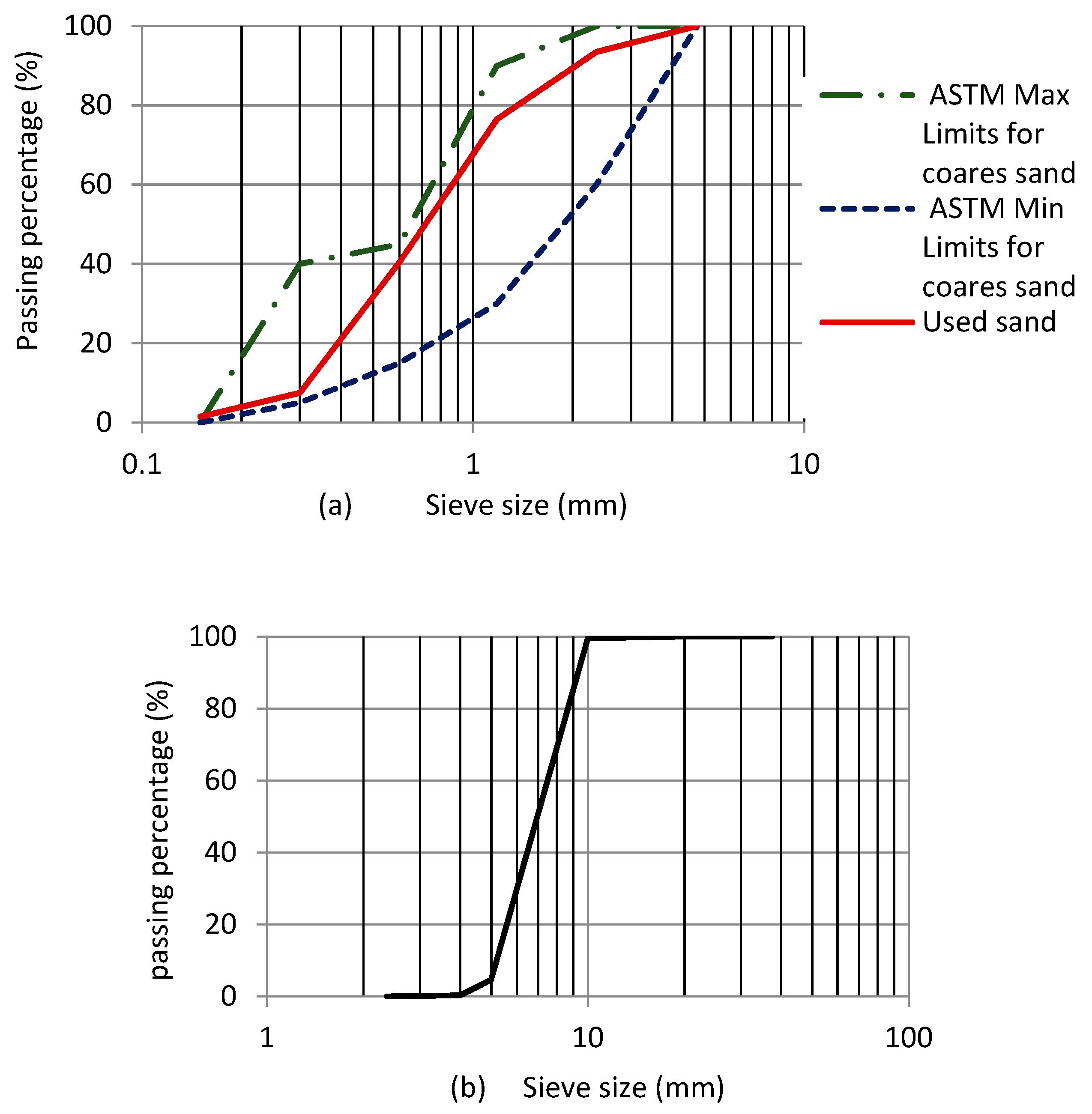
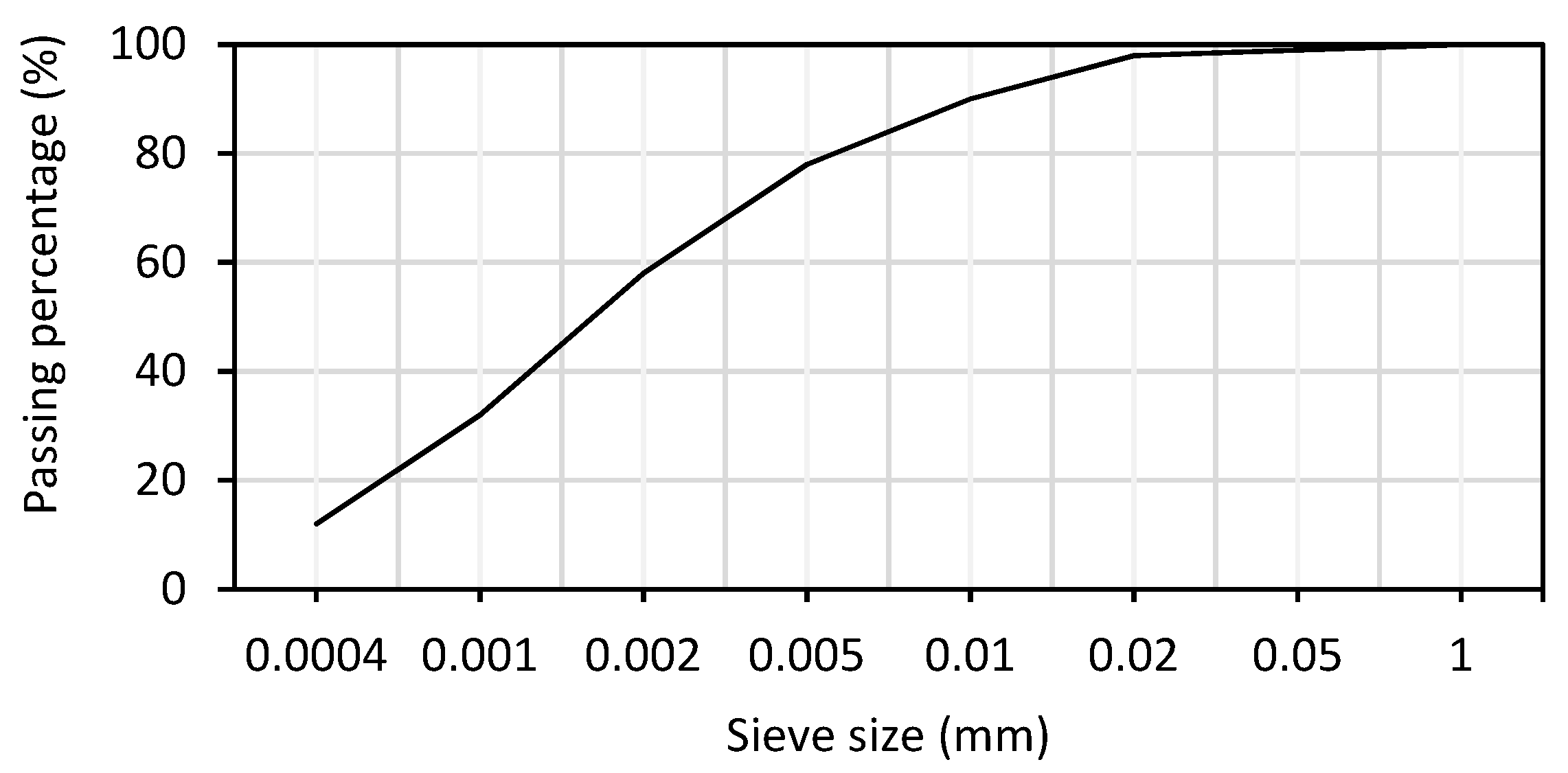
2.1. Raw Materials

The mixture consisted of ordinary Portland cement, water, fine and coarse aggregate, superplasticizer, silica fume, and glass fibers. The proportions of the SCC mix, as well as the components and their amounts, are described in Table 1. Natural river sand passing through a 5 mm sieve and fractured dolomite angular aggregates passing thru a 9.5 mm sieve were used as fine and coarse aggregates. Figure 1 depicts the fine and coarse aggregate particle size distributions. By cement weight, 25% silica fume was added. The silica fumes had the following properties: 2.1 specific gravity and 172,000 cm2 specific area per gram. The size distribution of silica fume particles is shown in Figure 2. In this experiment, a modified polycarboxylate aqueous solution with a specific gravity of 1.19 was utilized as a third-generation superplasticizer (Viscocrete 3425). It meets ASTM C-494 requirements [55]. The utilized glass fibers (Figure 3) were found have length of 6 to 13 mm, diameter of 13 μm, 0.91 g/cm3 density, 150 m2/kg specific surface area, 1700 MPa tensile strength, 72 GPa modulus of elasticity, and very high corrosion resistance. Tap water was used for mixing concrete and curing.
Five SCC mixtures were created in this project: The first SCC mix contained no fibers (control mix), the second mix (SCC-L1) contained 1% glass fibers with a 13 mm length, the third mix (SCC-L2) contained 0.5% glass fibers with a 13 mm length, the fourth mix (SCC-S1) contained 1% glass fibers with a 6 mm length, and the fifth mix (SCC-S2) contained 0.5% glass fibers with a 6 mm length. The components for each mixture were 420 kg/m3 ordinary Portland cement, 1% super-plasticizer, 45% water, and 25% silica fume with 0.5 or 1% glass fibers by volume.

2.2. Mixing, Moulding, and Curing

The dense packing principle was taken into consideration when creating the mix design for SCC samples. In dry conditions in a rotary mixer (Figure 4), Portland cement, silica fumes, and aggregate were mixed before super-plasticizer and water were added. Fibers were added to dry components before water was added, and then additives were added to the SCC mixtures. Compression, tension, and bending tests were conducted using a 100 mm cube, a 100 mm diameter by 200 mm high cylinder, and a 100 mm × 100 mm × 300 mm prism, respectively. To verify the self-compacting properties of mixtures, necessary experiments were run on SCC in its fresh state. This comprised L-box and GTM screen stability, as well as slump flow and flow velocity T50.

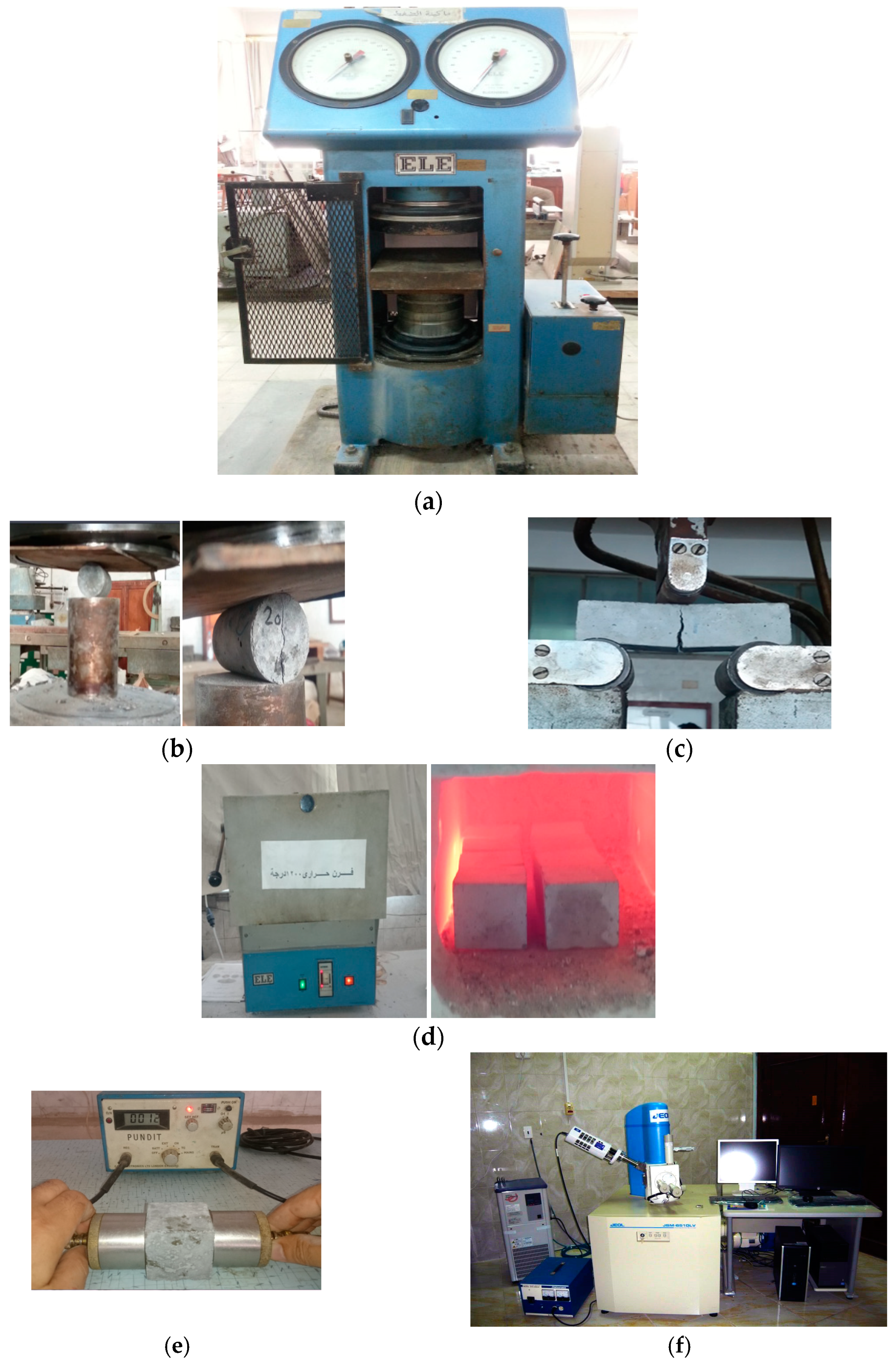
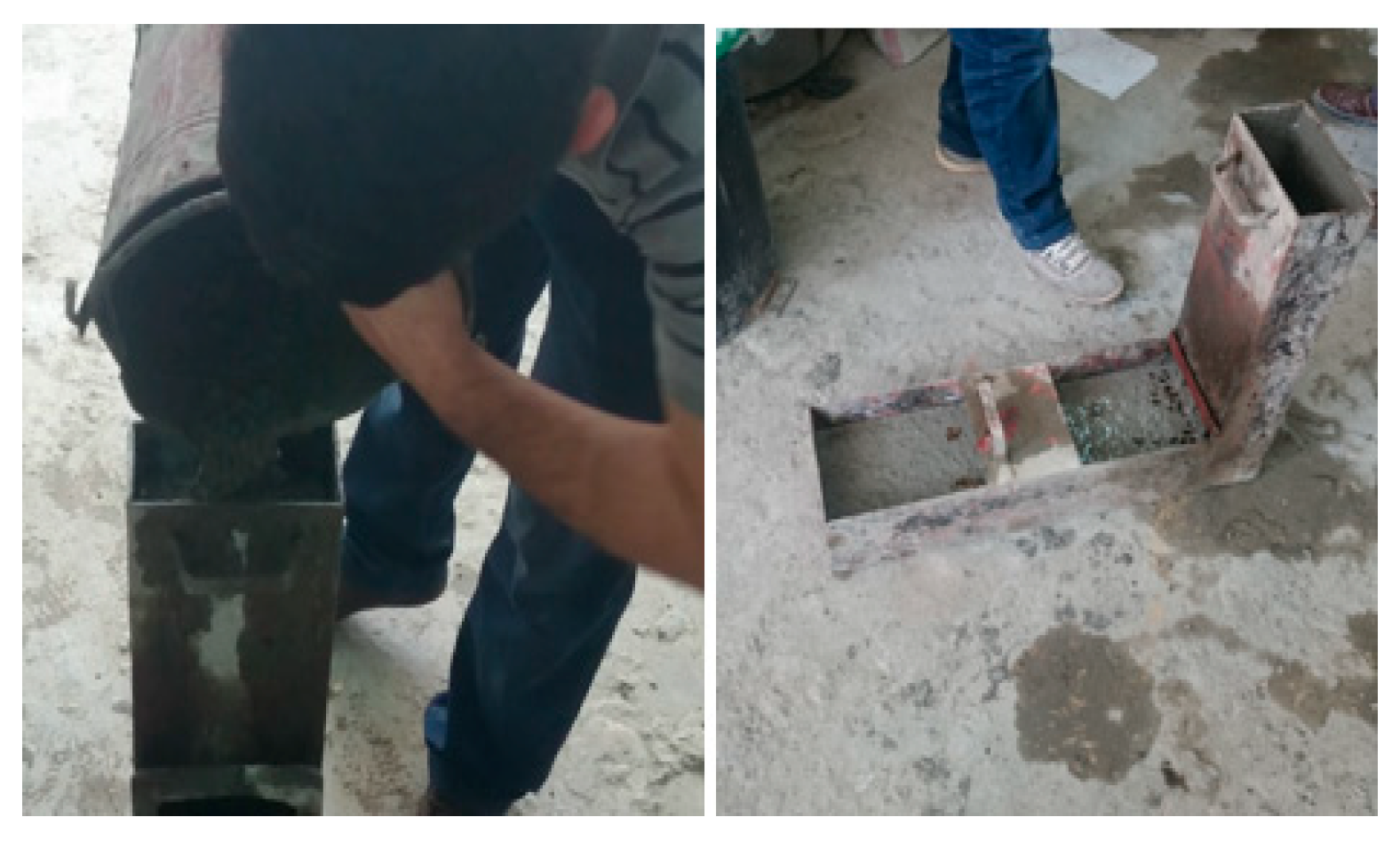
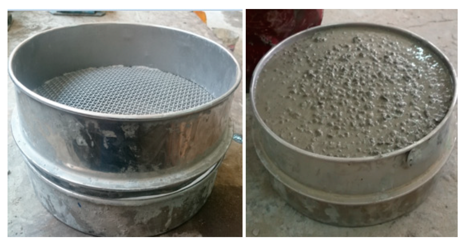
2.3. Tests Procedure

After the sample processing period was completed and before heating in the electric oven, the weight and speed of the ultrasonic pulse were calculated. Using an electric oven, samples were heated at 5 °C/min to 200, 400, 600, and 800 °C. After that, the temperature was maintained at the same level for an hour to ensure that all of the samples were the same temperature.
After each cycle, the temperature was cooled to room temperature. The samples were tested for compressive, tensile, and flexural strengths, as well as mass loss and ultrasonic speed after being removed from the oven. The compressive strength test was carried out according to ASTM C109-20 [56]. The tensile strength was tested according to ASTM C496 [57]. ASTM C293 [58] was used to conduct the flexural strength test. The ultrasonic pulse velocity (UPV) was determined using ASTM C597 [59]. Figure 5 shows the compressive strength test, splitting tensile strength test, flexural strength test, electrical furnace that was used for heating the samples, ultrasonic pulse velocity test, and scanning electron microscope.

3. Results and Discussion

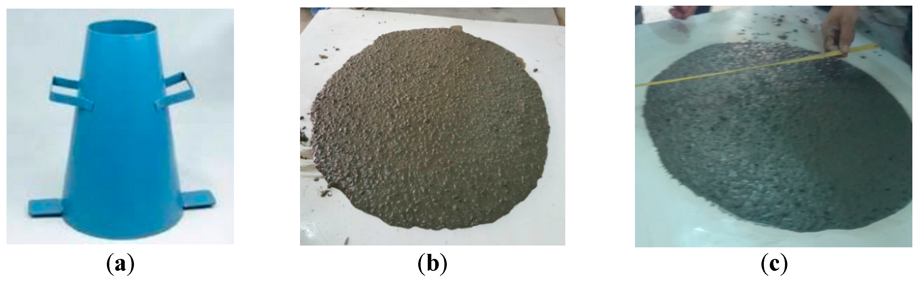
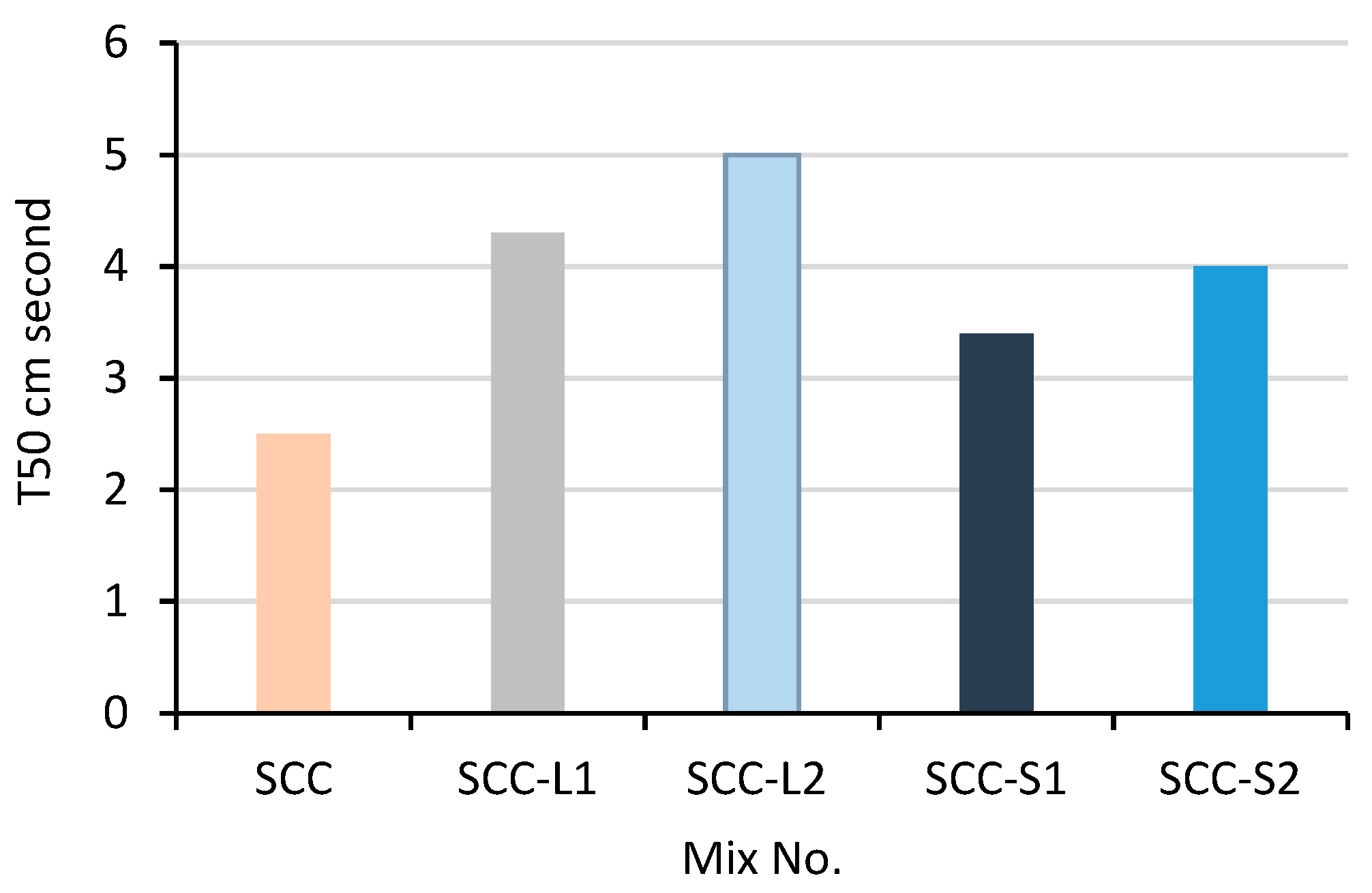
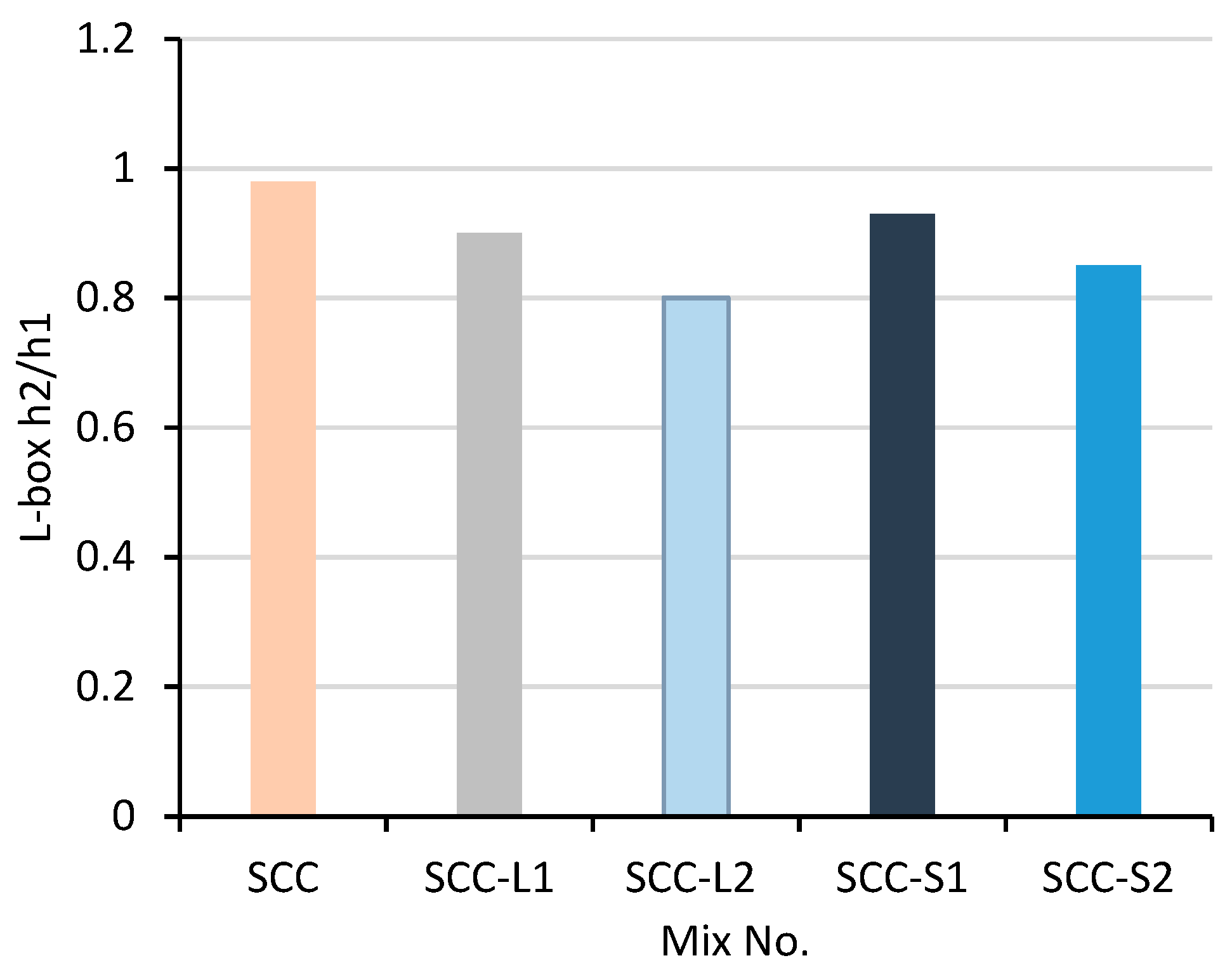
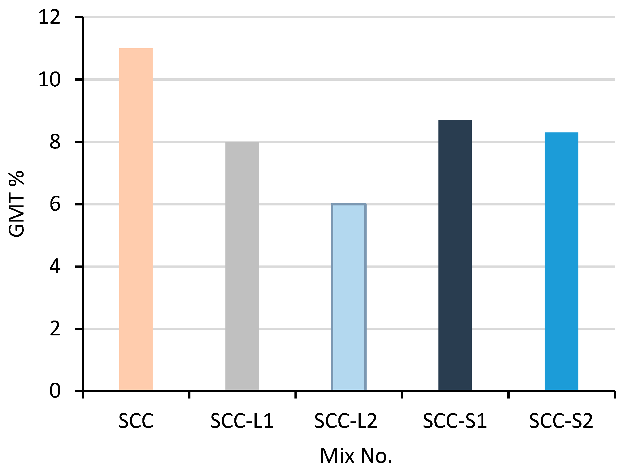
3.1. Properties of Fresh SCC and Fresh SCC with Glass Fibers

SCC behavior is described, categorized, and evaluated in its early stages. The stated principles indicated in guidelines like EFNARC [59] are a method of identifying SCC behavior and determining whether it meets certain precise conditions for its use or not. Table 2 lists the slump flow, T50, L-box, and screen stability grid test method (GTM) test findings for the five SCC mixtures, as well as the EFNARC limits. Figure 6, Figure 7 and Figure 8 show the slump flow test of SCC, L-box test of SCC, and screen stability (GTM) test of SCC, respectively. In Figure 9, Figure 10, Figure 11 and Figure 12, the values of (D) reflect the largest spread diameter, T50 values represent the time needed for the concrete flowing to achieve a diameter of 0.5 m, and (H2/H1) is a symbol for the blocking ratio. Figure 3 and Figure 4 show D and (H2/H1) in ascending order, whereas Figure 4 shows T50 in ascending order.
Table 2 contains the workability test results for SCC samples. The flow test revealed a decline in workability with the inclusion of glass fibers. Even when calculating T50 cm time, it is clear that extra time is needed for laying fresh concrete. As a result, fiber addition lowers workability and stiffens concrete. The flow value in the L-box test demonstrated a decrease in workability with the addition of fibers.
Figure 9, Figure 10, Figure 11 and Figure 12 show that the SCC criteria mentioned in the EFNARC specifications are met by all of the mixtures. As a result, in terms of filling and passing ability, all of the mixtures are considered to have great homogeneity and workability. When the flow is running or stopped, there is no segmentation or bleeding.
The plain SCC mixture is clearly a low-viscosity concrete, whereas the mixture with glass fibers is a high-viscosity concrete. This property is due to higher friction among aggregate grains and fibers, as well as higher viscosity due to the addition of fiber [61].
Table 2 and Figure 9, Figure 10, Figure 11 and Figure 12 show that introducing 1% glass fibers with lengths of 13 and 6 mm reduces slump flow by 5.1 and 17.7%, increases T50 by 72 and 100%, reduces L-box by 8.2 and 18.4%, and reduces GTM by 27.3 and 45.5%, respectively. Introducing 0.5% glass fibers with lengths of 13 and 6 mm reduces slump flow by 3.8 and 15.2%, increases T50 by 36 and 60%, reduces L-box by 5.1 and 13.3%, and reduces GTM by 21 and 24.5%, respectively. This reduction in workability results from the addition of glass fibers, which act as a buffer against mixture flow. The SCC’s characteristics are listed in Table 2, and it can only be classified and presented as an SCC if it satisfies all the requirements. These findings are consistent with the findings of other investigators [62,63].

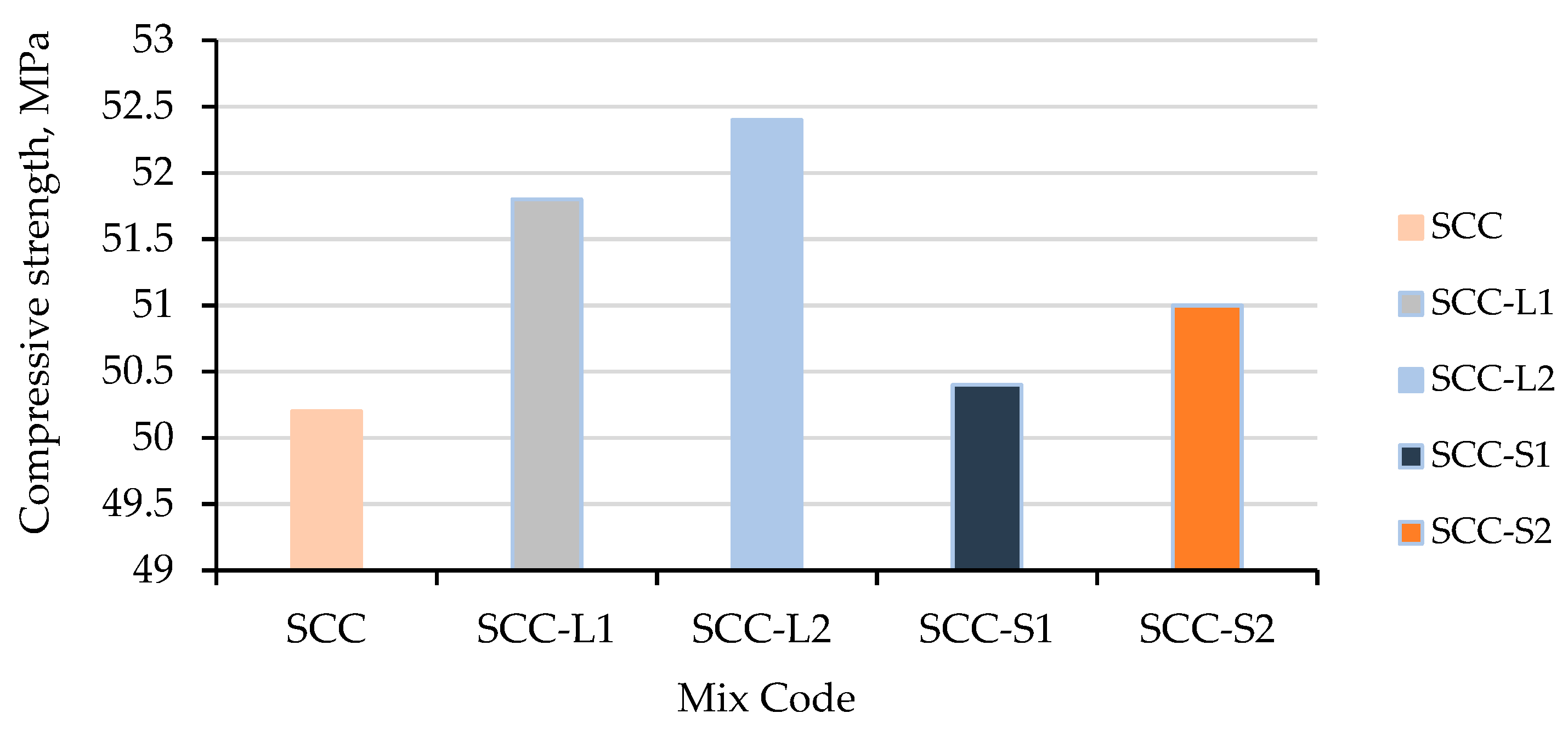
3.2. Compressive Strength
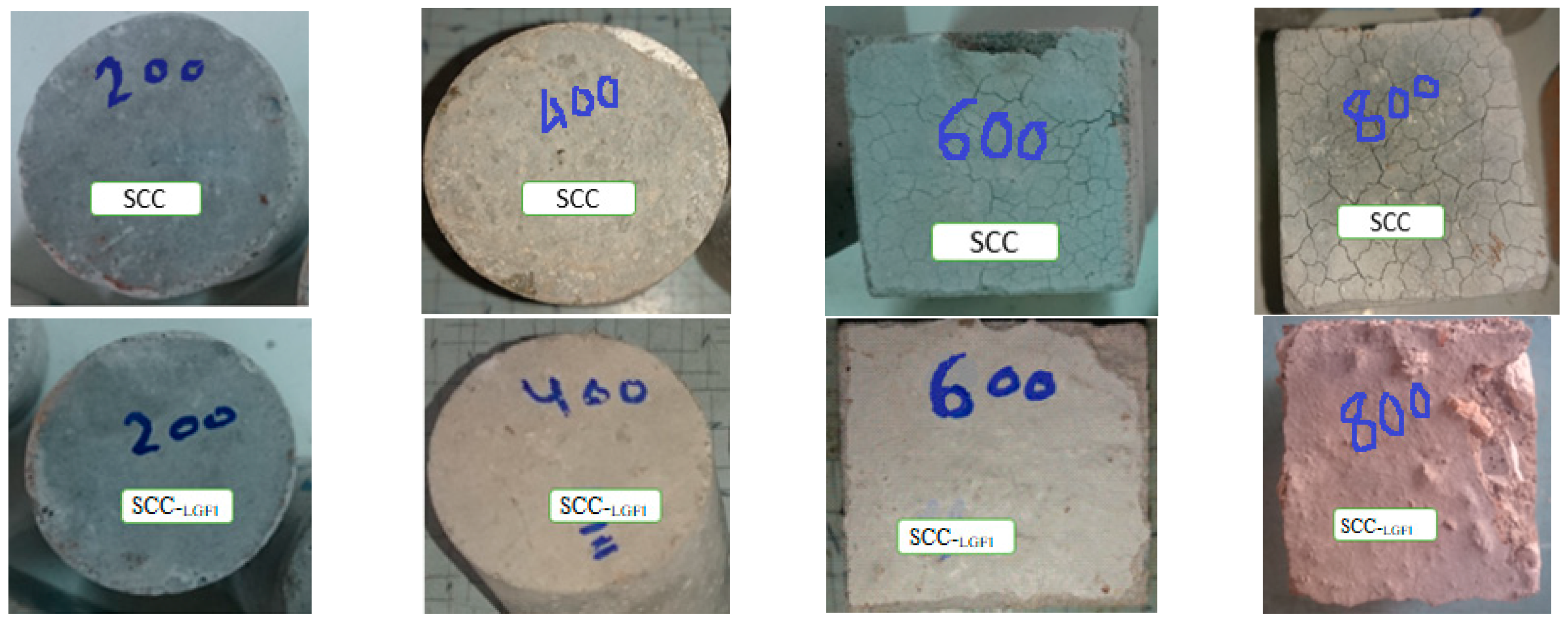
The average values of three 100 mm cubes were used to calculate the compressive strength. The compressive strength test was carried out according to ASTM C109-20 [56]. Three cubes were used to conduct this test of each mix at each step of heating. Results for the 28-day compressive strength of SCC with and without glass fibers are shown in Table 3 and Figure 13 and Figure 14.
The compressive strength values for SCC specimens with and without glass fibers at room temperature are shown in Figure 13. SCC without fibers at room temperature achieved a compressive strength value of 50.2 MPa after 28 days. Samples of SCC with glass fibers showed an increase in compressive strength at room temperature. In comparison to control mixes, the compressive strength of SCC containing 1% glass fibers with lengths of 13 and 6 mm increased by about 3.2 and 4.4%, respectively, while that of SCC containing 0.5% glass fibers with lengths of 13 and 6 mm increased by about 0.4 and 1.6%, respectively. The bridging of a pre-existing crack in the interfacial transition zone (ITZ) and the addition of fiber, which improves the interface between the hardened paste and the aggregate, could both be responsible for this increase in strength [30]. The findings of this study are consistent with those of previous studies [30,64,65]. Progressive failure occurred in SCC samples with fibers, and the fibers linked the segments. In SCC samples without fibers, failure occurs quickly, and the cube breaks apart into several pieces. The failure pattern is shown in Figure 15.
The compressive strength of all the SCC samples increased when they were heated up to 200 °C, reaching about 0.6% for samples without glass fibers, 1 and 7.8% for samples containing 1% glass fibers with lengths of 13 and 6 mm, and 1.4 and 5.9% for samples containing 0.5% glass fibers with lengths of 13 and 6 mm, respectively. Significant changes in the compressive strength of SCC specimens were prevented at up to 200 °C by the subsequent hydration of unhydrated cement particles as a result of an internal autoclaving effect brought on by high temperature and water evaporation [66,67]. All SCC samples showed an initial rise in compressive strength at about 200 °C followed by a fall at 400 °C. A diminishing trend was seen after increasing the temperature from 200 to 600 °C, especially for the control SCC sample. The physical and mechanical properties of the SCC samples with and without fibers significantly degraded at 300 °C. In samples heated to 600 °C, mechanical characteristics were linked to physical characteristics (appearance of cracking). Comparing samples that were left at room temperature to those that were heated to 400 and 600 °C, the compressive strength values of plain SCC, SCC-L1, SCC-L2, SCC-S1, and SCC-S2 decreased by approximately 39 and 66%, 28 and 65%, 27.4 and 61.7%, 14 and 63%, and 18 and 62.7%, respectively. When the temperature reached 800 °C, the compressive strength of each specimen rapidly decreased, falling to 4.6, 6.4, 7.2, 6.2, and 5.8 MPa for the plain SCC, SCC-L1, SCC-L2, SCC-S1, and SCC-S2 samples, respectively. This means that at 800 °C, the samples only retained 9.2, 12.4, 13.7, 12.3, and 11.4%, respectively, of their original strength. The loss of SCC compressive strength is related to the collapse of the interface link induced by incompatible volume changes among aggregate and cement paste throughout heating and cooling. Calcium hydroxide dehydrates as the temperature exceeds (400 °C), leading the cement paste to expand. Most quartz-like aggregates achieve a crystalline transition at about 600 °C, generating substantial concrete expansion and fracturing [36]. Additionally, at 600 and 800 °C, the mechanical characteristics of all samples continued to deteriorate due to the heat decomposition of cement components. Above 350 °C, the compressive strength of lime dramatically decreased due to a substantial expansion that occurred along with the rehydration process. Additionally, the disintegration of C-S-H gel began at about 560 °C, which led to a minor decline in compressive strength [67,68,69].
Comparing plain samples without fibers at 200, 400, 600, and 800 °C, compressive strength is lower in SCC-L1 samples by about 3.6, 22, 5.9, and 39%; in SCC-L2 samples by about 1.2, 19.6, 13.5, and 34.8% percent; in SCC-S1 samples by about 11.9, 47, 14, and 56.5%; and in SCC-S2 samples by about 6.9, 35.6, 11.8, 26%, respectively. This could be owing to the elevated temp altering the structure of concrete, as mentioned in the previous statement. The findings of this study are consistent with those of previous studies [30,70].
The fibers are effective until the concrete reaches 700 °C, at which point concrete becomes brittle and crumbly and loses its adhesion strength with the fibers. The degradation of cement-hydrating elements, as well as concrete expansion during heat and vapor pressure from water gel and pores, all help in the creation of cracks [71].

3.3. Spalling

Spalling is the process of removing concrete from a structure’s surface [72,73]. The samples are subjected to a complete visual evaluation after being subjected to extreme temps to evaluate visible cracking and spalling on their surfaces. Figure 16 shows the surface characteristics of SCC samples with and without glass fibers at high temps. With temperatures at 200 °C, there was no visible cracking or breakage for SCC samples with and without fibers. Around 400 °C, some SCC samples exhibited some spalling on the corners and edges. Microcracks began to appear in massive amounts above 400 °C. Rapid spalling occurred in SCC samples and they were fully damaged from 600 °C to 800 °C (see Figure 17); the findings of this study confirm Kanema’s findings [74]. Low permeability in concrete is related to a dense microstructure that prevents water vapors from dispersing owing to heat, leading to higher pore pressure.
The glass fiber-reinforced self-compacting concrete (GFR-SCC) specimens spalled from 300 °C to 400 °C (Figure 17), became extensively spalled from 400 °C to 600 °C, and were fully damaged from 600 °C to 800 °C. Glass fibers cannot prevent RPC from spalling throughout a fire, according to the findings.
Intense spalling was seen on GFR-SCC samples, most probably due to decreased microfractures and glass fiber permeability. Low permeability combined with a thick SCC microstructure prevents vapor from dispersing during extreme temps, leading to pore water pressure build-up. Because of its poor permeability and thick microstructures, the mortar’s bond strength deteriorates faster than other moderate and high-strength mortars. As a result, the matrix’s physicochemical bonding characteristics suffer a severe loss [75]. The spalling effect caused by a rise in temperature resulted in a decrease in SCC’s compressive strength [76].
Glass fibers can be used to modify pore refining in the microstructure of cement pastes at the initial phases of combustion (200 °C) [77]. The microstructure photo in Figure 18a illustrates these findings. Despite the fact that cracks appeared at 200 °C, the fibers were capable of binding to the concrete structure and offering bridging effects. Around 200 °C, the edge form and pointed ends of fibers could still be seen; however, at 400 °C, they vanished. When glass fiber is steadily heated from the ambient temperature, it becomes softer as the temperature rises. Glass fibers lose their shape as the temperature rises, changing from a stable solid to a pliable phase, as shown in Figure 18b at 400 °C

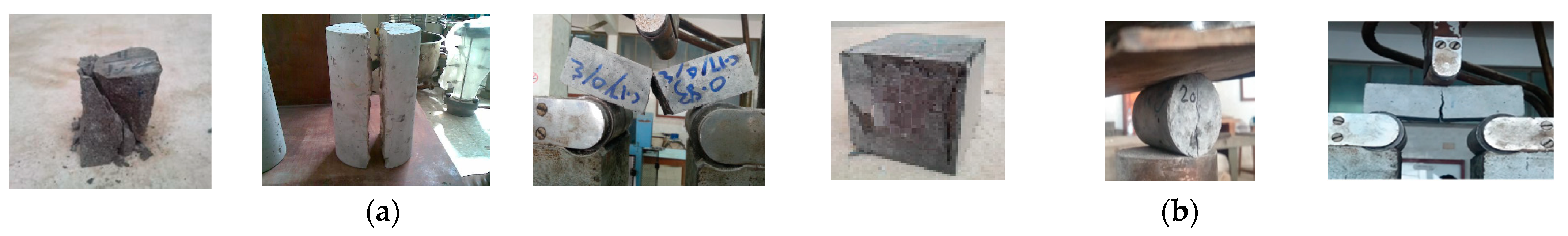
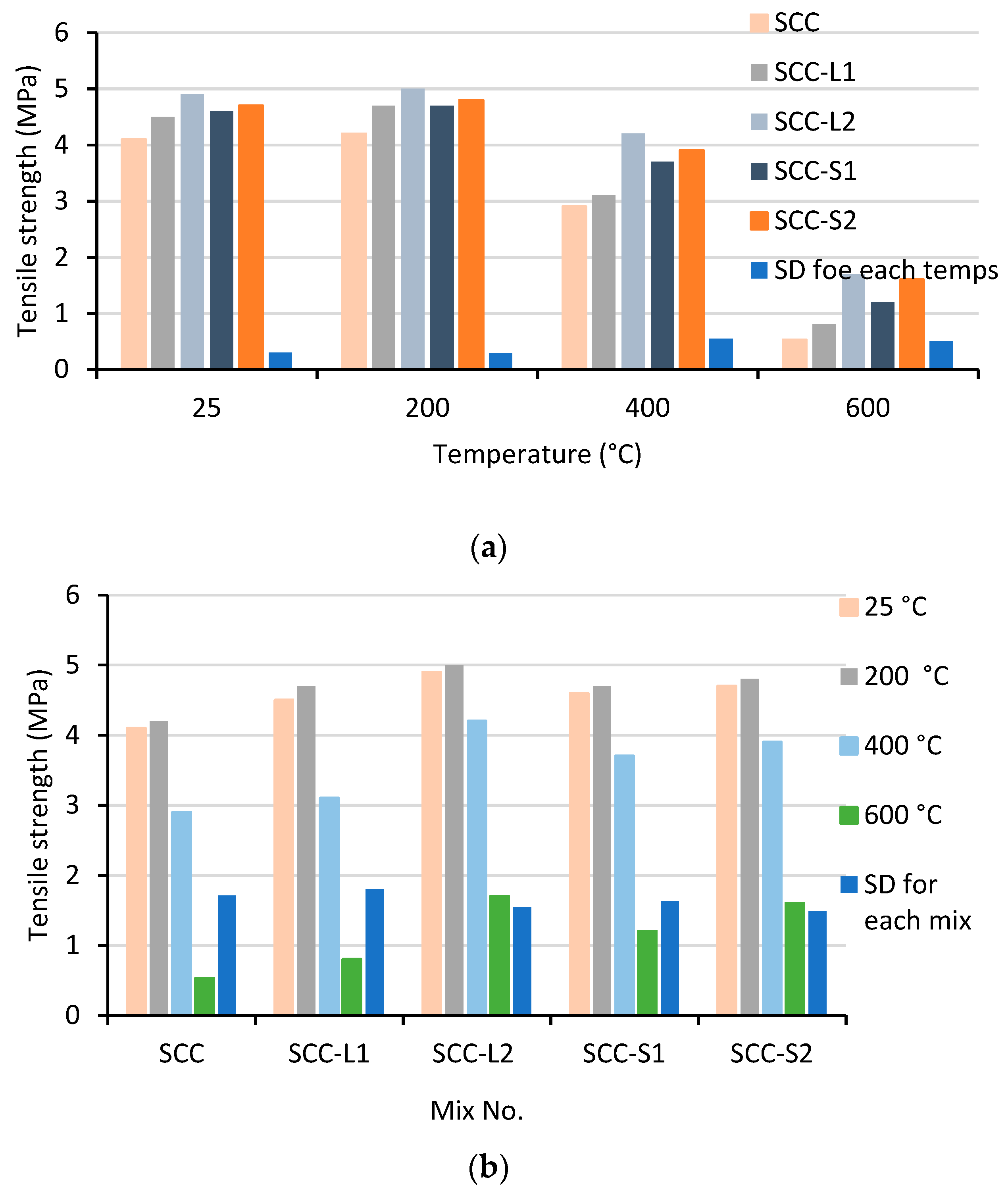
3.4. Splitting Tensile Strength

Table 4 displays the average results of the splitting tensile strength tests performed on three 100 mm by 200 mm cylinders. The tensile strength was tested according to ASTM C496 [57]. This test of each mixture at each stage of heating was performed using three cylinders. Since concrete is often not designed to sustain direct stress, understanding the tensile strength can aid in estimating the load which will induce fracture. Tensile splitting strength is a crucial component in crack development and, as a result, in predicting concrete durability. Crack-free concrete is necessary to sustain structural integrity and, in many circumstances, avoiding corrosion [78].
Table 4 and Figure 19 and Figure 20 display the findings for the 28-day tensile strength of SCC with and without glass fibers. Figure 20 displays the data for the splitting tensile strength for SCC specimens with and without glass fibers at room temperature. After 28 days, SCC at room temperature without fibers reached a splitting tensile strength value of 4.1 MPa. The splitting tensile strength of SCC samples containing glass fibers increased at room temperature. SCC containing 1% glass fibers with lengths of 13 and 6 mm increased in splitting tensile strength by about 9.8 and 19.5%, respectively, in comparison to control mixes, while SCC containing 0.5% glass fibers with lengths of 13 and 6 mm increased by about 12.2 and 14.6%, respectively. Increased splitting tensile strength may also be due to improved uniformity from vibration-free manufacture. The findings of this study are consistent with those of previous studies [65,79]. In specimens with fibers, fibers help to hold the cylinder pieces together when they fail, preserving the integrity of the entire component and connection. Figure 15 depicts the failure pattern.
The tensile strength of each SCC sample initially increased at about 200 °C and then decreased at 400 °C. Particularly for the control SCC sample, a decreasing trend was observed after raising the temperature from 200 to 600 °C. When heated to 200 °C, the tensile strength of each SCC sample increased, reaching 2.4% for SCC samples without glass fibers, 4.4% and 2.04% for SCC samples with 1% glass fibers with lengths of 13 and 6 mm, and 2.2% and 2.1% for SCC samples with 0.5% glass fibers with lengths of 13 and 6 mm, respectively. Increased hydration of cement could be the main source of improved tensile splitting strength whenever the temperature goes up to 200 °C.
Tensile strength values of plain SCC, SCC-L1, SCC-L2, SCC-S1, and SCC-S2 decreased by roughly 29.3 and 87.1%, 31.1 and 82.2%, 19.6 and 74%, 14.3 and 65.3%, and 17 and 66%, respectively, when samples heated to 400 and 600 °C were compared to samples left at room temperature. All SCC specimens lost all of their original tensile strength as soon as the temperature reached 800 °C. The differential of thermal expansion between both the aggregates and the cement paste and between the dry cement paste and aggregate degradation could all play a role in the loss of strength [80].
The results show a larger improvement in tensile strength in SCC samples with glass fibers than in samples without fibers. The increase is around 11.9, 6.9, and 51 % for SCC-L1 samples; 11.9, 27.6, and 126% for SCC-L2 samples; 19, 44.8, and 220% for SCC-S1 samples; and 14.3, 34.5, and 202% for SCC-S2 samples, respectively, at 200, 400, and 600 °C. This might be as a result of the fibers’ impact on the structure of the concrete, as demonstrated by the strength qualities [71].

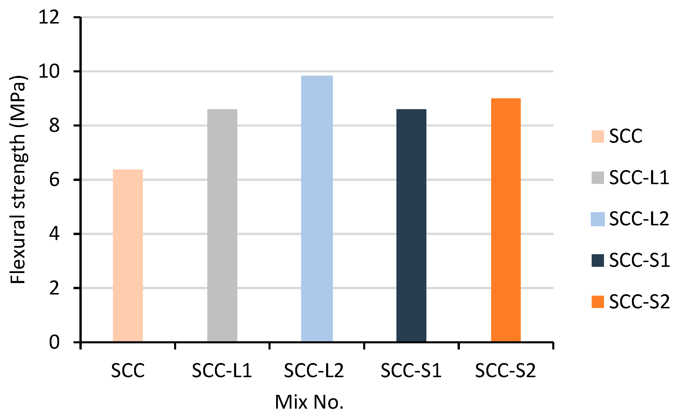
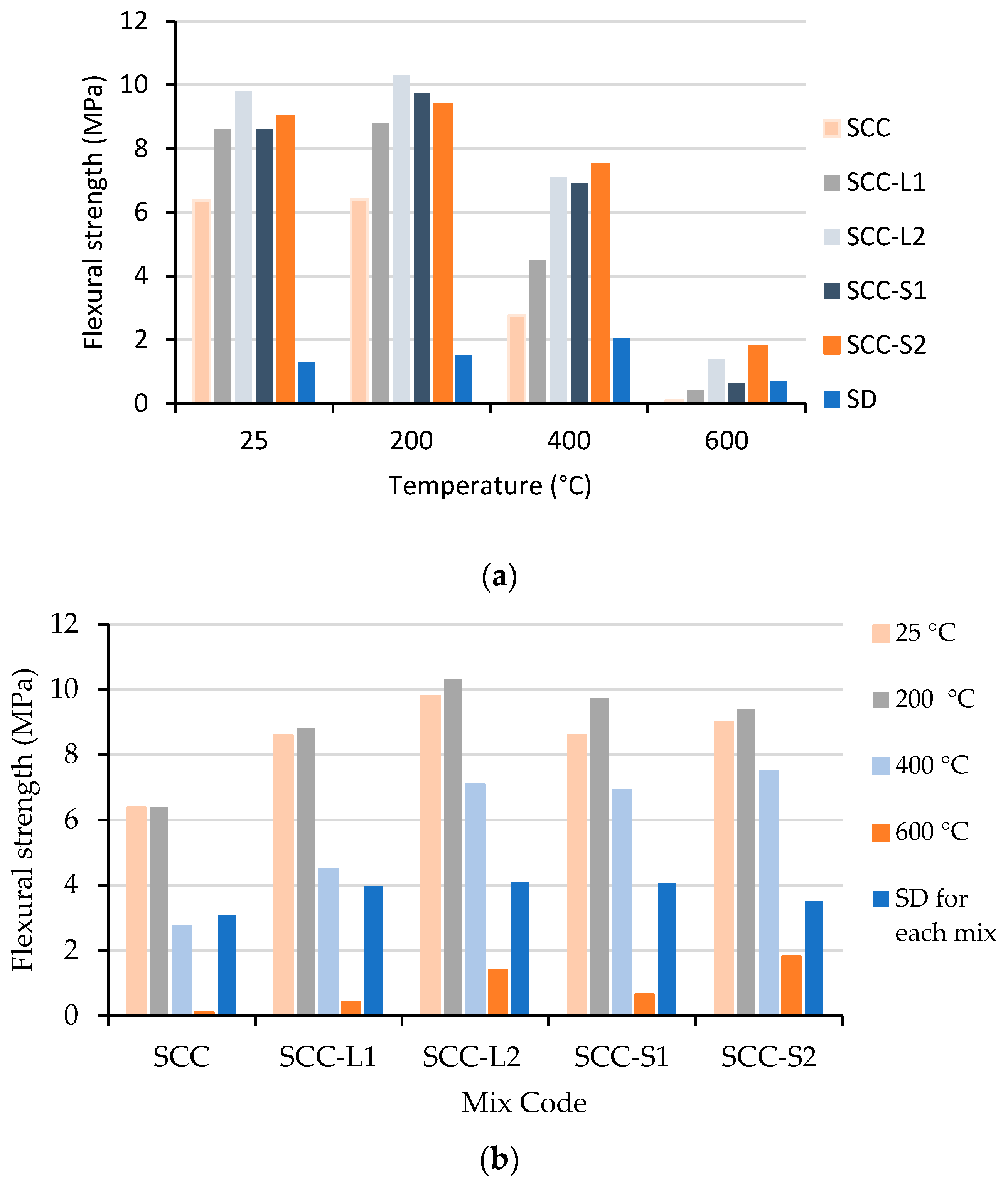
3.5. Flexural Strength

Table 5 shows the average test results of three 100 mm × 100 mm × 300 mm prisms at 28 days of age. ASTM C293 [58] was used to conduct the flexural strength test. In this experiment, flexural testing was carried out on a simple concrete prism. Three prisms were used to conduct this test on each mixture at each heating step.
The results for the 28-day flexural strength of SCC with and without glass fibers are shown in Table 5 and Figure 21 and Figure 22. The data for the flexural strength of SCC specimens with and without glass fibers at room temperature are shown in Figure 22. The flexural strength of SCC at room temperature without fibers was 6.375 MPa after 28 days. At room temperature, the flexural strength of SCC samples containing glass fibers increased. In comparison to control mixes without fibers, the flexural strength of SCC containing 1% glass fibers with lengths of 13 and 6 mm increased by about 34.9 and 53.7%, respectively, while SCC containing 0.5% glass fibers with lengths of 13 and 6 mm increased by about 34.9 and 41.2%, respectively. The higher flexural strength of SCC may result from crack restriction by fibers. The results of this study are in agreement with those of previous studies [64,79]. When prism components in samples with fibers collapse, the fibers aid to keep them together, maintaining the integrity of the entire member and connection. The failure pattern is shown in Figure 15.
At roughly 200 °C, each SCC sample’s flexural strength began to rise, and at 400 °C, it began to fall. Increasing the temperature from 200 to 600 °C resulted in a declining trend, especially for the control SCC sample. The flexural strength of each SCC sample increased when heated to 200 °C, reaching 0.4% for SCC samples without glass fibers, 2.3% and 5.1% for SCC samples with 1% glass fibers with lengths of 13 and 6 mm, and 13.3 % and 4.4% for SCC samples with 0.5% glass fibers with lengths of 13 and 6 mm, respectively. The key factor contributing to enhanced flexural strength when the temperature reaches 200 °C may be an increased hydration process. SCC samples lose their flexural strength at high temperatures. When samples heated to 400 and 600 °C were compared to samples left at room temperature, the flexural strength values of plain SCC, SCC-L1, SCC-L2, SCC-S1, and SCC-S2 decreased by approximately 56.9 and 98.4%, 47.7 and 95.3%, 27.6 and 85.7%, 19.7 and 92.6%, and 16.7 and 80%, respectively. All SCC specimens lost all of their original flexural strength as soon as the temperature reached 800 °C. This can be a result of the concrete structure being affected by the high temperature. Cement paste expands as a result of calcium hydroxide dehydrating at temperatures over (400 °C). Numerous micro- and macrocracks formed in the samples as a consequence of the heat incompatibility among cement paste and aggregates, lowering flexural strength [80].
The findings reveal that SCC samples with glass fibers improved in flexural strength more than samples without fibers. At 200 °C, the increase is around 37.5% for SCC-L1 samples, 60.95% for SCC-L2 samples, 52.35% for SCC-S1 samples, and 46.95% for SCC-S2 samples, respectively. This might be as a result of the fibers’ impact on concrete’s structure, as observed by its strength properties [71].

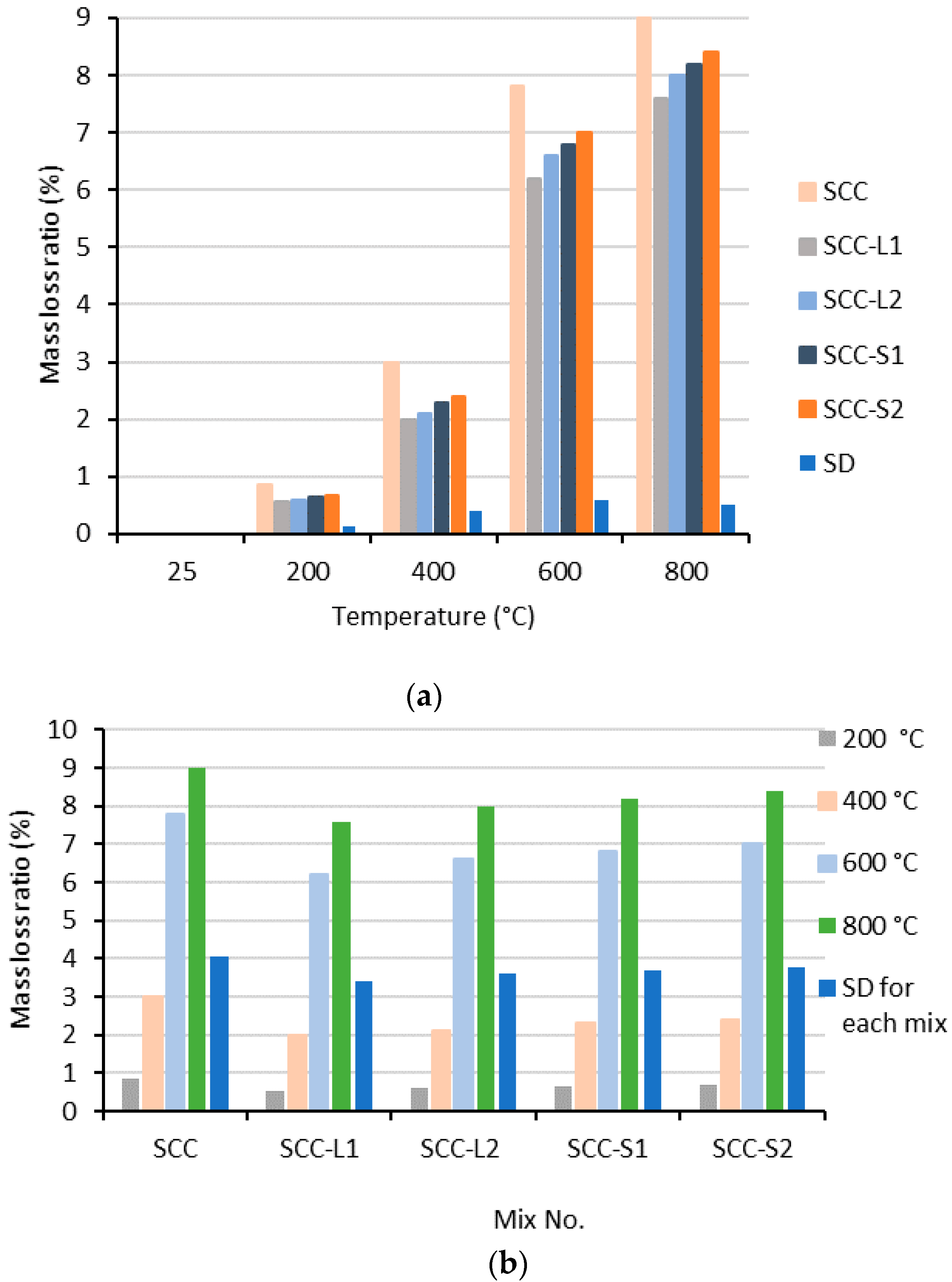
3.6. The Mass Loss Ratio

The difference between the weights before and after heating was used to calculate mass loss. Dehydration, thermal degradation of the cement’s components, and spalling from the top layer were the main causes of mass loss at high temperatures [68,81,82]. High temperatures produce cracks that spread and might possibly explode. The mass loss of the examined SCC samples at high temperatures is shown in Figure 23.
No substantial mass loss occurred for the investigated SCC specimens between 200 and 400 °C; however, the evaporation of the bound water is the primary cause of the documented low mass loss % in this temperature range [83]. However, for plain SCC, SCC-L1, SCC-L2, SCC-S1, and SCC-S2, there is a sharp increase in mass loss at 600 °C. Compared to 200 °C, their mass loss increased by more than ten times, reaching 7.8%, 6.2%, 6.6%, 6.8%, and 7.0%, respectively. By raising the temperature to 800 °C, the mass loss of plain SCC, SCC-L1, SCC-L2, SCC-S1, and SCC-S2 reached 9.0%, 7.6%, 8.0%, 8.2%, and 8.2%, respectively.

3.7. Ultrasonic Pulse Velocity (UPV)

The ultrasonic pulse velocity (UPV) was determined using ASTM C597 [59]. A UPV test was used to determine how much the SCC sample degraded when exposed to high temperatures. In the UPV test, an ultrasonic wave is transmitted through the cube specimens, and the length of time it takes for the wave to pass is measured. The uniformity and quality of the concrete improve with increasing speed, and there are less cracks and voids. The UPV was determined by dividing the width of a structure by the pulse’s transit time. The quality range of the concrete sample is shown in Table 6.
The UPV results of all SCC samples exposed to various high temperatures are shown in Figure 24. Every data point is provided by an average of three SCC cube sampling tests. The SCC’s UPV at room temperature without fibers was 4.42 km/s. The UPV of SCC samples with glass fibers increased at room temperature, and SCC-LGF2 had a slightly higher UPV than other SCC mixtures. The UPV of SCC containing 1% glass fibers with lengths of 13 and 6 mm increased by approximately 8.4 and 15%, respectively, when compared to control mixes without fibers, while SCC containing 0.5% glass fibers with lengths of 13 and 6 mm increased by approximately 5.5 and 6.5%, respectively. Increased UPV readings could potentially be a result of better homogeneity brought on by vibration-free manufacturing.
The UPV of each SCC sample started to increase at around 200 °C and started to decrease at about 400 °C. A diminishing trend was seen when the temperature was raised from 200 to 800 °C, especially for the control SCC sample. When heated to 200 °C, the UPV of each SCC sample rose, reaching 8.1% for plain SCC samples, 7.7% for SCC-L1, 8.1% for SCC-L2, 8.6% for SCC-S1, and 12.8% for SCC-S2, respectively. When the temperature hits 200 °C, an accelerated hydration process may be the main factor enhancing UPV. High temperatures cause SCC samples to lose their UPV. The UPV values of plain SCC, SCC-L1, SCC-L2, SCC-S1, and SCC-S2 decreased by approximately 42.5 and 70.7%, 37.4 and 71.6%, 34.2 and 70.3%, 36.6 and 68.6%, and 31.4 and 69.9%, respectively, when samples heated to 400 and 600 °C were compared to samples left at room temperature. The rising temperature, which causes total physical degradation of SCC specimens, may be responsible for the low UPV readings for samples. The rate of microcracks increased and the SCC quality decreased at 600 °C, causing a higher drop in UPV values than at 200 and 400 °C. Microcracking has a considerable impact on the way pulses are transmitted through concrete. As a result, as the temperature rises, a crucial signal of material fracture is a decreasing pulse speed. Due to the high temperatures, thermal expansion and drying of the concrete may result in fissures forming. The pulse velocity of the SCC samples increases as a result of the fractures or micro-pathways that lead to more cracks. Microcracks, consequently, result in a slowing of the pulse and low UPV levels [84].
As compared to SCC samples without fibers, the results indicate a greater improvement in UPV in SCC samples with glass fibers. At 200, 400, 600, and 800 °C, the increase is approximately 8, 15, 6, and 11.3% for SCC-L1 samples; 15.8, 26.7, 14.6, and 21.5% for SCC-L2 samples; 5.1, 16.3, 12, and 9.2% for SCC-S1 samples; and 48, 53.6, 36.7, and 27.9% for SCC-S2 samples. The strength characteristics of the concrete, which are supported by the fibers’ influence on its structural makeup [71], may be the cause of this.

4. Effects or Spin-Offs of the Study in Practice

In practical applications, according to the results of the study, self-compacting glass fiber concrete should be used in construction projects when subjected to elevated temperatures of 200 °C. The addition of silica fume and glass fibers enhanced the concrete’s performance for both SCC samples with and without glass fibers and remained intact at 200 °C.

5. Conclusions

Several experiments were carried out throughout this work to analyze variations in the mechanical properties of SCC samples exposed to high temperatures up to 800 °C and to investigate the effects of adding glass fibers on the SCC’s fresh and hardening properties. The primary conclusions that can be drawn from the results of this study are as follows:
  • In terms of filling and passing ability, all SCC combinations are regarded as having acceptable consistency and workability. The addition of glass fiber to SCC diminishes workability but it does so within the permissible limit of EFNARC. There is neither bleeding nor segregation while the flow is running or stopped.
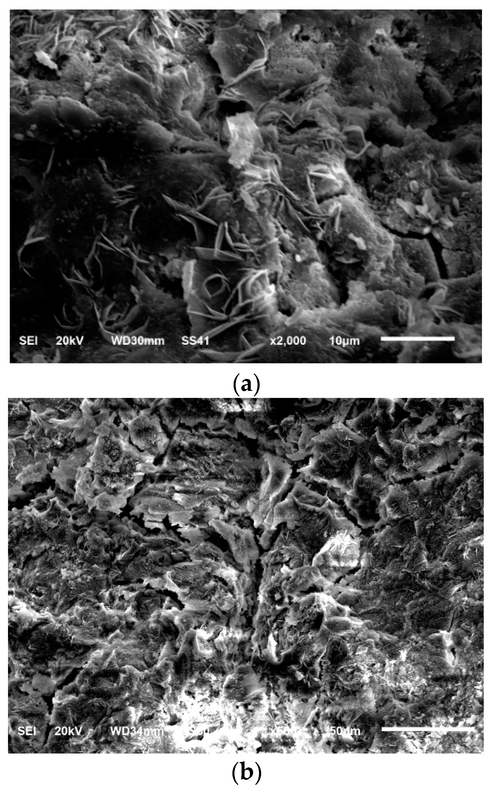
  • When glass fibers were added to SCC samples, their mechanical strength rose. This improvement in mechanical properties can be attributed to fiber influence, which successfully inhibits the development of cracks by forming a strong relationship between the fibers and matrix. The SCC’s mechanical strength was increased as a result of the SCC’s improved energy absorption capacity. Additionally, fibers can join micro- and macrofractures, delaying the spread of significant fractures and switching the failure mode from brittle to flexible.
  • Glass fibers were added to SCC samples to improve their mechanical strength, and as a result, the improvements in SCC samples with glass fibers are greater than in those samples without fibers. The influence of fibers, which successfully prevent crack development by forming a strong bond between the fibers and matrix, can be attributed to this improvement in mechanical qualities. As a result, the SCC’s capacity to absorb energy was improved, increasing its mechanical strength. Additionally, fibers have the ability to join micro- and macrofractures, delaying the spread of significant fractures and changing the failure mode from brittle to flexible.
  • The mechanical properties of specimens containing glass fibers increased at up to 200 °C but then declined at 400 °C, whereas the SCC-L2 mixture exhibited better mechanical properties.
  • SCC samples with and without fibers did not break or show any signs of visual cracking at 200 °C. Some SCC samples showed some corner and edge spalling at temperatures of about 400 °C. Above 400 °C, a large number of microcracks started to develop. Between 600 and 800 °C, SCC samples experienced rapid spalling and complete destruction.
  • The GFR-SCC specimens cracked between 300 °C and 400 °C, spalled significantly between 400 °C and 600 °C, and were completely destroyed between 600° C and 800°C. According to the results, glass fibers cannot stop RPC from spalling over the course of a fire.
  • For the examined SCC specimens, there was no significant mass loss between 200 and 400 °C. At 600 °C, however, there is a rapid rise in mass loss, and this mass loss increased by more than ten times when compared to 200 °C.
  • At room temperature, the UPV of SCC samples with glass fibers grew, and SCC-L2 exhibited a somewhat higher UPV than other SCC mixes. The results show that at 200, 400, 600, and 800 °C, SCC samples containing glass fibers exhibit a larger improvement in UPV than SCC samples without fibers. At about 200 °C, the UPV of each SCC sample began to rise, then at roughly 400 °C, it began to fall. When the temperature was increased from 200 to 800 °C, UPV decreased, especially for the control SCC sample.

6. Recommendation for Future Work

Regarding the effect of elevated temperature on GFR-SCC, the following points should be researched.
  • The effects of glass fibers on the mechanical and thermal properties of SCC exposed to varying periods of high temperatures.
  • The effect of adding carbon fibers to SCC that has been exposed to high temperatures on mechanical and thermal properties.

Author Contributions

Conceptualization, H.K.S. and A.A.A.N.; methodology, H.K.S.; software, H.K.S.; validation, A.A.A.N., H.K.S. and G.F.H.; formal analysis, H.K.S.; investigation, A.A.A.N.; resources, H.K.S.; data curation, H.K.S.; writing—original draft preparation, H.K.S.; writing—review and editing, G.F.H.; visualization, A.A.A.N.; supervision, G.F.H.; project administration, A.A.A.N.; funding acquisition, G.F.H. All authors have read and agreed to the published version of the manuscript.

Funding

This research received no external funding.

Institutional Review Board Statement

Not applicable.

Informed Consent Statement

Not applicable.

Data Availability Statement

The original contributions presented in the study are included in the article, further inquiries can be directed to the corresponding author.

Conflicts of Interest

The authors declare no conflicts of interest.

Abbreviations

SCCself-compacting concrete
GFR-SCCglass fiber-reinforced self-compacting concrete
SCC-L1mixture contains 1% glass fibers of a length of 13 mm
SCC-L2mixture contains 0.5% glass fibers of a length of 13 mm
SCC-S1mixture contains 1% glass fibers of a length of 6 mm
SCC-S2mixture contains 0.5% glass fibers of a length of 6 mm

References

  1. Ahmed, G.H.; Ahmed, H.; Ali, B. Alyousef R Assessment of High Performance Self-Consolidating Concrete through an Experimental and Analytical Multi-Parameter Approach. Materials 2021, 14, 985. [Google Scholar] [CrossRef] [PubMed]
  2. Geiker, M.; Jacobsen, S. Self-compacting concrete (SCC). In Developments in the Formulation and Reinforcement of Concrete, 2nd ed.; Mindess, S., Ed.; Woodhead: Vancouver, BC, Canada, 2020; Volume 10, pp. 229–256. [Google Scholar]
  3. Anıl, N. Mechanical Properties of Steel Fiber Reinforced Self-Compacting Concrete. Int. J. Eng. Technol.-IJET 2018, 4, 2018. [Google Scholar]
  4. Megid, W.A.; Khayat, K.H. Effect of concrete rheological properties on quality of formed surfaces cast with self-consolidating concrete and superworkable concrete. Cem. Concr. Compos. 2018, 93, 75–84. [Google Scholar] [CrossRef]
  5. El-Chabib, H.; Syed, A. Properties of self-consolidating concrete made with high volumes of supplementary cementitious materials. J. Mater. Civ. Eng. 2013, 25, 1579–1586. [Google Scholar] [CrossRef]
  6. Sideris, K.K.; Tassos, C.; Chatzopoulos, A.; Manita, P. Mechanical characteristics and durability of self-compacting concretes produced with ladle furnace slag. Constr. Build. Mater. 2018, 170, 660–667. [Google Scholar] [CrossRef]
  7. Zinkaah, O.H.; Sultan, H.K.; Al-Rifaie, A.; Alridha, Z. Influence of Strut Geometry on the Size Effect of FRP Reinforced Simply Supported Deep Beams: A Theoretical Analysis. Math. Model. Eng. Probl. 2022, 9, 411–417. [Google Scholar] [CrossRef]
  8. Aziz, H.Y.; Sultan, H.K.; Abbas, B.J. Simulation and Style Design of Bridge Stability Supported on Large Diameter Piles. Math. Model. Eng. Probl. 2021, 8, 961–966. [Google Scholar] [CrossRef]
  9. Łázniewska-Piekarczyk, B. Investigations on the relationship between porosity and strength of admixtures modified high performance self-compacting concrete. J. Civ. Eng. Manag. 2016, 22, 520–528. [Google Scholar] [CrossRef]
  10. Huseien, G.F.; Sam, A.R.M.; Alyousef, R. Texture, morphology and strength performance of self-compacting alkali-activated concrete: Role of fly ash as GBFS replacement. Constr. Build. Mater. 2020, 270, 121368. [Google Scholar] [CrossRef]
  11. Sultan, H.K. Designing reinforced HSC rectangular beams using optimization techniques. Pollack Period. J. 2023, 18, 20–25. [Google Scholar] [CrossRef]
  12. Sultan, H.K.; Abbas, B.J.; Al Khuzaie, H.M.A.; Alsheakayree, T.K.Q. Designing High Strength Concrete Grade T-Beams at the Lowest Possible Cost. Math. Model. Eng. Probl. 2023, 10, 1369–1376. [Google Scholar] [CrossRef]
  13. Hameed, A.A.; Al-Sherrawi, M.H. Influence of Steel Fiber on the Shear Strength of a Concrete Beam. Civ. Eng. J. 2018, 4, 1501–1509. [Google Scholar] [CrossRef]
  14. Faridmehr, I.; Shariq, M.; Plevris, V.; Aalimahmoody, N. Novel hybrid informational model for predicting the creep and shrinkage deflection of reinforced concrete beams containing GGBFS. Neural Comput. Appl. 2022, 34, 13107–13123. [Google Scholar] [CrossRef]
  15. Sultan, H.K.; Mohammed, A.T. Assessing of the common strengthening methods for existing RC buildings. Pollack Period. J. 2023, 18, 6–11. [Google Scholar] [CrossRef]
  16. Kumar, P.; Kumar, R.; Gupta, K. Study on Normally Vibrated Concrete to Self-Compacting Concrete. J. Ceram. Concr. Technol. 2016, 1, 1–18. [Google Scholar]
  17. Sultan, H.K.; Mohammed, A.T.; Qasim, O.D.; Maula, B.H.; Aziz, H.Y. Ductility Factor Evaluation of Concrete Moment Frame Retrofitted by FRP Subjected to Seismic Loads. Int. Rev. Civ. Eng. (I.RE.C.E.) 2020, 11, 275–282. [Google Scholar] [CrossRef]
  18. Sultan, H.K.; Huseien, G.F. Minimum Shear Reinforcement for Reactive Powder Concrete Beams. ENG 2024, 5, 801–818. [Google Scholar] [CrossRef]
  19. Alyousef, R.; Benjeddou, O.; Khadimallah, M.A.; Mohamed, A.M.; Soussi, C. Study of the Effects of Marble Powder Amount on the Self-Compacting Concretes Properties by Microstructure Analysis on Cement-Marble Powder Pastes. Adv. Civ. Eng. 2018, 2018, 6018613. [Google Scholar] [CrossRef]
  20. Domone, P.L. A review of the hardened mechanical properties of self-compacting concrete. Cem. Concr. Compos. 2007, 29, 1–12. [Google Scholar] [CrossRef]
  21. Foroughi-Asl, A.; Dilmaghani, S.; Famili, H. Bond strength of reinforcement steel in self-compacting concrete. Int. J. Civ. Eng. 2008, 6, 24–33. [Google Scholar]
  22. Kang, S.-H.; Hong, S.-G.; Moon, J. Shrinkage characteristics of heat-treated ultra-high performance concrete and its mitigation using superabsorbent polymer based internal curing method. Cem. Concr. Compos. 2018, 89, 130–138. [Google Scholar] [CrossRef]
  23. Zhutovsky, S.; Kovler, K. Influence of water to cement ratio on the efficiency of internal curing of high-performance concrete. Constr. Build. Mater. 2017, 144, 311–316. [Google Scholar] [CrossRef]
  24. Alyousef, R.; Khadimallah, M.A.; Soussi, C.; Benjeddou, O.; Jedidi, M. Experimental and Theoretical Study of a New Technique for Mixing Self-Compacting Concrete with Marble Sludge Grout. Adv. Civ. Eng. 2018, 2018, 3283451. [Google Scholar] [CrossRef]
  25. Alabduljabbar, H.; Alyousef, R.; Alrshoudi, F.; Alaskar, A.; Fathi, A.; Mohamed, A.M. Mechanical effect of steel fiber on the cement replacement materials of self-compacting concrete. Fibers 2019, 7, 36. [Google Scholar] [CrossRef]
  26. Kannan, V.; Jerin, C.; Murali, D.K. A Review on Self Compacting Concrete. Int. J. Adv. Res. Eng. Manag. 2015, 1, 64–68. [Google Scholar]
  27. Nadeem, A.; Memon, S.A.; Lo, T.Y. The performance of fly ash and metakaolin concrete at elevated temperatures. Constr. Build. Mater. 2014, 62, 67–76. [Google Scholar] [CrossRef]
  28. Memon, S.A.; Shah, S.F.A.; Khushnood, R.A.; Baloch, W.L. Durability of sustainable concrete subjected to elevated temperature–A review. Constr. Build. Mater. 2019, 199, 435–455. [Google Scholar] [CrossRef]
  29. Alyousef, R.; Benjeddou, O.; Soussi, C.; Khadimallah, M.A.; Mohamed, A.M. Effects of Incorporation of Marble Powder Obtained by Recycling Waste Sludge and Limestone Powder on Rheology, Compressive Strength, and Durability of Self-Compacting Concrete. Adv. Mater. Sci. Eng. 2019, 2019, 4609353. [Google Scholar] [CrossRef]
  30. Ahmad, S.; Umar, A.; Masood, A. Properties of normal concrete, self-compacting concrete and glass fibre-reinforced self-compacting concrete: An experimental study. Procedia Eng. 2017, 173, 807–813. [Google Scholar] [CrossRef]
  31. Hake, S.L.; Shinde, S.S.; Bhandari, P.K.; Awasarmal, P.R.; Kanawade, B.D. Effect of Glass Fibers on Self-Compacting Concrete. E3S Web Conf. 2020, 170, 6018. [Google Scholar] [CrossRef]
  32. Bogas, J.; Hawreen, A. Capillary Absorption and Oxygen Permeability of Concrete Reinforced with Carbon Nanotubes. Adv. Civ. Eng. Mater. 2019, 8, 307–326. [Google Scholar]
  33. Hawreen, A.; Bogas, J.A.; Kurda, R. Mechanical Characterization of Concrete Reinforced with Different Types of Carbon Nanotubes. Arab. J. Sci. Eng. 2019, 44, 8361–8376. [Google Scholar] [CrossRef]
  34. Abu Maraq, M.A.; Tayeh, B.A.; Ziara, M.M.; Alyousef, R. Flexural behavior of RC beams strengthened with steel wire mesh and self-compacting concrete jacketing—Experimental investigation and test results. J. Mater. Res. Technol. 2020, 10, 1002–1019. [Google Scholar] [CrossRef]
  35. Li, Y.; Pimienta, P.; Pinoteau, N.; Tan, K.-H. Effect of aggregate size and inclusion of polypropylene and steel fibers on explosive spalling and pore pressure in ultra-high-performance concrete (UHPC) at elevated temperature. Cem. Concr. Compos. 2019, 99, 62–71. [Google Scholar] [CrossRef]
  36. Ali, S.; Saeed, H.; Behzad, T. Residual Strength and Microstructure of Fiber Reinforced Self-Compacting Concrete Exposed to High Temperatures. Constr. Build. Mater. 2020, 230, 116969. [Google Scholar] [CrossRef]
  37. Cifuentes, H.C.; Leiva, M.F.; Fernández-Pereira, C. Effects of fibers and rice husk ash on properties of heated high-strength concrete. Mag. Concr. Res. 2012, 64, 457–470. [Google Scholar] [CrossRef]
  38. Zuhair, M.; Deshmukh, S.K. Effect of different fibers on compressive strength of self-compacting concrete at elevated temperature. IOP Conf. Ser. Mater. Sci. Eng. 2018, 410, 012007. [Google Scholar] [CrossRef]
  39. Qasim, O.A.; Sultan, H.K. Experimental investigation of effect of steel fiber on concrete construction joints of prism. IOP Conf. Ser. Mater. Sci. Eng. 2020, 745, 012170. [Google Scholar] [CrossRef]
  40. Sultan, H.K.; Alyaseri, I. Effects of elevated temperatures on mechanical properties of reactive powder concrete elements. Constr. Build. Mater. 2020, 261, 120555. [Google Scholar] [CrossRef]
  41. Ombres, L.; Mazzuca, P.; Verre, S. Effects of Thermal Conditioning at High Temperatures on the Response of Concrete Elements Confined with a PBO-FRCM Composite System. J. Mater. Civ. Eng. 2021, 34, 04021413. [Google Scholar] [CrossRef]
  42. Bakhtiyari, S.; Allahverdi, A.; Rais-Ghasemi, M.; Zarrabi, B.A.; Parhizkar, T. Self-compacting concrete containing different powders at elevated temperatures–Mechanical properties and changes in the phase composition of the paste. Thermochim. Acta 2011, 514, 74–81. [Google Scholar] [CrossRef]
  43. Vanwalleghem, H.; Blontrock, H.; Taerwe, L. Spalling tests on self-compacting concrete. In Proceedings of the International RILEM Symposium on Self-Compacting Concrete, Proceedings PRO, Reykjavik, Iceland, 17–20 August 2003. [Google Scholar]
  44. Sultan, H.K.; Zinkaah, O.H.; Rasheed, A.A.; Alridha, Z.; Alhawat, M. Producing Sustainable Modified Reactive Powder Concrete Using Locally Available Materials. Innov. Infrastruct. Solut. 2022, 7, 342. [Google Scholar] [CrossRef]
  45. Noumowé, A.; Carré, H.; Daoud, A.; Toutanji, H. High-strength self-compacting concrete exposed to fire test. J. Mater. Civ. Eng. 2006, 18, 754–758. [Google Scholar] [CrossRef]
  46. Haddad, R.H.; Odeh, R.A.; Amawi, H.A.; Ababneh, A.N. Thermal performance of self-compacting concrete: Destructive and nondestructive evaluation. Can. J. Civ. Eng. 2013, 40, 1205–1214. [Google Scholar] [CrossRef]
  47. Persson, B. Fire resistance of self-compacting concrete, SCC. Mater. Struct. 2004, 37, 575–584. [Google Scholar] [CrossRef]
  48. Subhan, A.; Arshad, U. Fibre-reinforced Self Compacting Concrete: A Review. IOP Conf. Ser. Mater. Sci. Eng. 2018, 377, 012117. [Google Scholar] [CrossRef]
  49. Farhad, A.; Jack, K. Assessment and development of high-performance fibre reinforced lightweight self-compacting concrete including recycled crumb rubber aggregates exposed to elevated temperatures F. Aslani J. Kelin/J. Clean. Prod. 2018, 200, 1009–1025. [Google Scholar]
  50. Asce, M.; Junbo, S.; Guanqi, H. Mechanical Behavior of Fiber Reinforced Self-Compacting Rubberized Concrete Exposed to Elevated Temperatures. J. Mater. Civ. Eng. 2019, 31, 04019302. [Google Scholar]
  51. Mahapatra, C.K.; Barai, S.V. Temperature impact on residual properties of self-compacting based hybrid fiber reinforced concrete with fly ash and colloidal nano silica. Constr. Build. Mater. 2019, 198, 120–132. [Google Scholar] [CrossRef]
  52. Yahy AL-Radi, H.H.; Dejian, S.; Sultan, H.K. Performance of Fiber Self-Compacting Concrete at High Temperatures. Civ. Eng. J. 2021, 7, 2083–2098. [Google Scholar] [CrossRef]
  53. Venkadachalam, G.; Kumar, M.D. Behaviour of Self Compacted Concrete Produced with Steel Fiber, Glass fiber and Polypropylene Fiber Additives Subjected To High Temperature. IOP Conf. Ser. Mater. Sci. Eng. 2020, 981, 042088. [Google Scholar] [CrossRef]
  54. Pathak, N.; Siddique, R. Properties of self-compacting-concrete containing fly ash subjected to elevated temperatures. Constr. Build. Mater. 2012, 30, 274–280. [Google Scholar] [CrossRef]
  55. ASTM C494; Standard Specification for Chemical Admixtures for Concrete. ASTM: West Conshohocken, PA, USA, 2017.
  56. ASTM C109/C109M-20; Standard Test Method for Compressive Strength of Hydraulic Cement Mortars. ASTM International: West Conshohocken, PA, USA, 2020.
  57. ASTM C496; Standard Test Method for Splitting Tensile Strength of Cylindrical Concrete Specimens; American Society for Testing and Materials Standard Practice C496. American Society for Testing and Materials: Philadelphia, PA, USA, 2017.
  58. ASTM C293; Standard Test Method for Flexural Strength of Concrete (Using Simple Beam with Center Point Loading). ASTM International: West Conshohocken, PA, USA, 2016.
  59. ASTM C597-16; Standard Test Method for Pulse Velocity through Concrete. ASTM International: West Conshohocken, PA, USA, 2016.
  60. EFNARC. Specification and Guidelines for Self-CompactingConcrete; European Federation for Specialist Construction Chemicals and Concrete: Brussels, Belgium, 2005. [Google Scholar]
  61. Mezzal, S.K.; Khalid, B.; Najim, K.N.; Al-Azzawi, Z. Residual Mechanical Properties of High Strength Self-Compacting Concrete with Reused Steel Fibers at High Temperatures. J. Green Eng. (JGE) 2020, 10, 14. [Google Scholar]
  62. Qasim, O.A. Ahmed AS High temperature effect on shear transfer strength of steel fiber reinforced self-compacting concrete. J. Eng. Appl. Sci. 2019, 14, 3158–3174. [Google Scholar] [CrossRef]
  63. Kumar, S.L.; Manasa, V.; Harish, M. Evaluation of workability characteristics of self-compacting concrete creep behavior of self-compacting concrete. Int. Res. J. Eng. Technol. (IRJET) 2018, 5, 1193–1198. [Google Scholar]
  64. Umar, A.; Al-Tamimi, A. Acritical study of the effect of viscosity modifying admixture and glass fibers on the properties of self-compacting concrete (SCC). J. Struct. Eng. 2011, 38, 153–1621. [Google Scholar]
  65. Salami, F.; Shami, N. Self-compacting concrete incorporating steel and polypropylene fibers: Compressive and tensile strengths, moduli of elasticity and rupture, compressive stress—Strain curve, and energy dissipated under compressive. Compos. Part B Eng. 2013, 53, 121–133. [Google Scholar]
  66. Lim, S.; Mondal, P. Effects of Nanosilica Addition on Increased Thermal Stability of Cement-Based Composite. ACI Mater. J. 2015, 112, 305–315. [Google Scholar] [CrossRef]
  67. Ma, Q.; Guo, R.; Zhao, Z.; Lin, Z.; He, K. Mechanical properties of concrete at high temperature—A review. Constr. Build. Mater. 2015, 93, 371–383. [Google Scholar] [CrossRef]
  68. Wang, G.; Zhang, C.; Zhang, B.; Li, Q.; Shui, Z. Study on the high-temperature behavior and rehydration characteristics of hardened cement paste. Fire Mater. 2015, 39, 741–750. [Google Scholar] [CrossRef]
  69. Arioz, O. Effects of elevated temperatures on properties of concrete. Fire Saf. J. 2007, 42, 516–522. [Google Scholar] [CrossRef]
  70. Ezziane, M.; Kadri, T.; Molez, L.; Jauberthie, R.; Belhacen, A. High temperature behaviour of polypropylene fibres reinforced mortars. Fire Saf. J. 2015, 71, 324–331. [Google Scholar] [CrossRef]
  71. Poon, C.; Shui, Z.; Lam, L.J. Compressive behavior of fiber reinforced high-performance concrete subjected to elevated temperatures. J. Cem. Concr. Res. 2004, 34, 2215–2222. [Google Scholar] [CrossRef]
  72. Ali, M.H.; Dinkha, Y.Z.; Haido, J.H. Mechanical properties and spalling at elevated temperature of high performance concrete made with reactive and waste inert powders. Eng. Sci. Technol. Int. J. 2017, 20, 536–541. [Google Scholar] [CrossRef]
  73. So, H.-S. Spalling Prevention of High Performance Concrete at High Temperatures. In High Performance Concrete Technology and Applications; InTech: London, UK, 2016. [Google Scholar]
  74. Kanema, M. Influence des Paramètres de Formulation Etmicrostructurauxsur le Comportement à Haute Température des Bétons. Ph.D. Thesis, Université de Cergy-Pontoise, Cergy, France, 2007. [Google Scholar]
  75. Parka, J.-J.; Yoob, D.-Y.; Kimb, S.; Kima, S.-W. Benefits of synthetic fibers on the residual mechanical performance of UHPFRC after exposure to ISO standard fire. Cem. Concr. Compos. 2019, 104, 103401. [Google Scholar] [CrossRef]
  76. Horszczaruk, E.; Sikora, P.; Cendrowski, K.; Mijowska, E. The effect of elevated temperature on the properties of cement mortars containing nanosilica and heavyweight aggregates. Constr. Build. Mater. 2017, 137, 420–431. [Google Scholar] [CrossRef]
  77. Kamali, M.; Ghahremaninezhad, A. An investigation into the hydration and microstructure of cement pastes modified with glass powders. Constr. Build. Mater. 2016, 112, 915–924. [Google Scholar] [CrossRef]
  78. Behnood, A.; Ghandehari, M. Comparison of compressive and splitting tensile strength of high-strength concrete with and without polypropylene fibers heated to high temperatures. Fire Saf. J. 2009, 44, 1015–1022. [Google Scholar] [CrossRef]
  79. Rathish, K.; Kumar Srikuth, K. Mechanical Characteristics of Polypropylene Fiber Reinforced Self Compacting Concrete. Asian J. Civ. Eng. (Build. Hous.) 2008, 9, 647–657. [Google Scholar]
  80. Corinaldesi, V.; Moriconi, G. Characterization of self-compacting concretes prepared with different fibers and mineral additions. Cem. Concr. Compos. 2011, 33, 596–601. [Google Scholar] [CrossRef]
  81. Düğenci, O.; Haktanir, T.; Altun, F. Experimental research for the effect of high temperature on the mechanical properties of steel fiber-reinforced concrete. Constr. Build. Mater. 2015, 75, 82–88. [Google Scholar] [CrossRef]
  82. Yüksel, I.; Siddique, R.; Özkan, Ö. Influence of high temperature on the properties of concretes made with industrial by-products as fine aggregate replacement. Constr. Build. Mater. 2011, 25, 967–972. [Google Scholar] [CrossRef]
  83. Gencel, O. Effect of elevated temperatures on mechanical properties of high-strength concrete containing varying proportions of hematite. Fire Mater. 2012, 36, 217–230. [Google Scholar] [CrossRef]
  84. IS 13311-1; Method of Non-Destructive Testing of Concrete, Part 1: Ultrasonic Pulse Velocity [CED 2: Cement and Concrete]. Bureau of Indian Standards: New Delhi, India, 1992.
Figure 1. Aggregate particle size distribution curve, (a) fine aggregate, (b) coarse aggregate.
Eng 05 00057 g001
Figure 2. Silica fume particle size distribution curve (from supplier).
Eng 05 00057 g002
Figure 3. The glass fiber used in preparation of the mixtures.
Eng 05 00057 g003
Figure 4. Dry mixing in a rotary mixer.
Eng 05 00057 g004
Figure 5. (a) Compressive strength test, (b) splitting tensile strength test, (c) flexural strength test, (d) the electrical furnace that was used for heating the samples, (e) ultrasonic pulse velocity test, and (f) scanning electron microscope.
Eng 05 00057 g005
Figure 6. (a) Slump cone, (b) slump flow test of SCC with glass fibers, and (c) slump flow test of SCC without glass fibers.
Eng 05 00057 g006
Figure 7. L-box test of SCC.
Eng 05 00057 g007
Figure 8. Screen stability (GTM) test of SCC.
Eng 05 00057 g008
Figure 9. Diameter of slump flow (mm).
Eng 05 00057 g009
Figure 10. Circle (50 cm dia.). Time required (T50).
Eng 05 00057 g010
Figure 11. The effect of fiber content on the blocking ratio.
Eng 05 00057 g011
Figure 12. The effect of fiber content on the segregation ratio.
Eng 05 00057 g012
Figure 13. Compressive strength of SCC mixes is affected by fiber dose at room temperatures.
Eng 05 00057 g013
Figure 14. SCC mixtures’ compressive strength at high temperature and SD (a) for each temperature and (b) for each mix.
Eng 05 00057 g014
Figure 15. Failure patterns of SCC samples. (a) Specimens without fibers. (b) Specimens with fibers.
Eng 05 00057 g015
Figure 16. Surface properties of SCC samples with and without glass fibers at 200, 400, 600, and 800 °C.
Eng 05 00057 g016
Figure 17. When SCC with and without glass fibers samples are heated to 450 °C, explosive spalling ensues.
Eng 05 00057 g017
Figure 18. SEM photos of GFR-SCC specimens after they have been exposed to a temperature of (a) 200 °C and (b) 400 °C (to the right).
Eng 05 00057 g018
Figure 19. Fiber dosage affects the tensile strength of SCC mixes at room temperatures.
Eng 05 00057 g019
Figure 20. Tensile splitting strengths of SCC mixes at temperatures ranging from 25 to 800 °C and SD (a) for each temperature and (b) for each mix.
Eng 05 00057 g020
Figure 21. Fiber dosage affects the flexural strength of SCC mixes at room temperature.
Eng 05 00057 g021
Figure 22. SCC mixes’ flexural strengths at various temperatures and SD (a) for each temperature and (b) for each mix.
Eng 05 00057 g022
Figure 23. Temperature-to-mass-loss-ratio relationship and SD (a) for each temperature and (b) for each mix.
Eng 05 00057 g023
Figure 24. Relationship between UPV and temperature and SD (a) for each temperature and (b) for each mix.
Eng 05 00057 g024
Table 1. The SCC mixes’ ingredients (kg/m3).
Mix No.CementSilica FumeAggregateWaterSuper-PlasticizerGlass Fibers
CoarseFine6 mm13 mm
SCC420105810.5810.51894.200
SCC-L1420105779.1779.11894.209
SCC-L2420105793.5793.51894.204.5
SCC-S1420105779.1779.11894.290
SCC-S2420105793.5793.51894.24.50
Table 2. Fresh properties of SCC mixtures with and without glass fibers.
Mix No.Slump-Flow mmT50 cm sL-Box (H2/H1)GTM (%)
SCC7902.50.9811
SCC-L17504.30.98
SCC-L265050.86
SCC-S17603.40.938.7
SCC-S267040.858.3
Limit of EFNARC (2005) [60]650–8002–50.8–1.0≤15
Table 3. All SCC mixes’ compressive strength at 28 days of curing.
Mix No.Compressive Strength at High Temp (MPa)SDCOV
25 °C200 °C400 °C600 °C800 °C
SCC50.2 (1)50.530.6174.620.255410.282
SCC-L151.8 (1)52.337.3186.420.475419.213
SCC-L252.4 (1)56.54519.47.221.652468.79
SCC-S150.4 (1)51.136.619.36.219.678387.217
SCC-S251.0 (1)5441.5195.821.007441.288
SD0.9322.4255.4371.0240.953
COV0.8685.88229.5651.0480.908
Note: The relative compressive strength of the various SCC mixtures is shown in brackets. SD is the standard deviation, and COV is the coefficient of variation.
Table 4. SCC mix tensile strength at 28 days of curing.
MixTensile Strength at Elevated Temp (MPa)SDCOV
25 °C200 °C400 °C600 °C
SCC4.14.202.900.531.7072.914
SCC-L14.54.703.10.801.7973.229
SCC-L24.95.004.201.71.5422.377
SCC-S14.604.703.71.21.6302.657
SCC-S24.74.83.91.61.4892.217
SD0.2970.2950.5460.503
COV0.0880.0870.2980.253
Table 5. SCC mix flexural strength at 28 days of curing (MPa).
MixAt Higher Temps, Relative Flexural Strength (MPa)SDCOV
25 °C200 °C400 °C600 °C
SCC6.3756.42.750.103.0639.379
SCC-L18.608.84.50.403.97915.829
SCC-L29.810.37.11.404.08316.670
SCC-S18.69.756.90.644.06116.490
SCC-S29.09.47.51.83.51312.343
SD1.2721.5162.0480.709
COV1.6182.2974.1930.503
Table 6. A concrete velocity-based quality evaluation criterion [84].
Pulse Velocity (km/s)Concrete Quality Grading
Above 4.5Excellent
3.5–4.5Good
3.0–3.5Medium
Below 3.0Doubtful
Disclaimer/Publisher’s Note: The statements, opinions and data contained in all publications are solely those of the individual author(s) and contributor(s) and not of MDPI and/or the editor(s). MDPI and/or the editor(s) disclaim responsibility for any injury to people or property resulting from any ideas, methods, instructions or products referred to in the content.

