Article

Development of a Methodology for Railway Bolster Beam Design Enhancement Using Topological Optimization and Manufacturing Constraints

Department of Industrial Engineering (DIEF), University of Florence, Via Santa Marta, 3, 50139 Florence, Italy
*
Author to whom correspondence should be addressed.
Eng 2024, 5(3), 1485-1498; https://doi.org/10.3390/eng5030079
Submission received: 28 May 2024 / Revised: 13 July 2024 / Accepted: 15 July 2024 / Published: 19 July 2024
(This article belongs to the Special Issue Feature Papers in Eng 2024)

Abstract

:
Rolling stock manufacturers are finding innovative structural solutions to improve the quality and reliability of railway vehicle components. Structural optimization processes represent an effective strategy for reducing manufacturing costs, resulting in geometries that are easier to design and produce combined with innovative materials. In this framework, the present paper proposes the development of a design methodology to innovate a railway bolster beam using topological optimization techniques, assessing the effect of different manufacturing constraints oriented to the casting process. A comprehensive numerical testing campaign was conducted to establish an effective testing procedure. Two different designs were obtained and compared, statically and dynamically, evaluating the difference in terms of mass, mechanical performance and manufacturability. Reductions in stress values up to 70% were observed, along with an 8% increase in the first natural frequency of the component, leading to beneficial effects in terms of stiffness. The methodology shows encouraging results to streamline the design of complex casting components, moving to a new generation of structural railway components.

1. Introduction

Recently, the demand for efficient and sustainable transportation has continued to grow, and the railway industry can meet this request. The imperative is to ensure the major reliability of its components and minimize the downtime of railway vehicles. For this reason, advancements in manufacturing techniques offer a promising path toward achieving these objectives, opening the door to significant improvements in the design, manufacturing and maintenance of railway components. Casting technologies can play a main role in these improvements, offering versatility, efficiency and cost-effectiveness. Furthermore, casting can be employed for both prototype development and high-volume production, making it a versatile choice for manufacturers seeking flexibility in their operations. It offers excellent material properties and performance characteristics, ensuring the final products meet demanding industry standards and specifications. With reference to the railway sector, main vehicle components like bogie frames and bolster beams have historically been made up with structural steel and complex welding techniques. This allows box-shaped geometries to be easily created to perform correctly under vehicle running conditions. However, all of this comes at a cost in terms of reliability and maintenance times due to the presence of welding, which is the most critical factor for railway components. Furthermore, unlike the casting process, this production method requires significantly longer production times and a limited reproducibility of solutions. In this context, transitioning from components designed for welding to ones designed for casting could be very complex, requiring a wide series of iterations to arrive at a final design. With this objective, structural optimization processes represent an efficient solution to significantly accelerate the process. In order to create a casting piece, it is essential to consider all the geometric characteristics the piece must possess, from reference dimensions to a geometry that enables the correct execution of the production process. In this paper, the authors compare the development of two different innovative designs for a railway bolster beam using structural optimization processes and manufacturing constraints. The project was conducted by exploiting Finite Element Analysis (FEA) combined with CAD techniques and structural optimization processes. In addition, it explored the use of spheroidal cast iron compared with structural steel. The strength of this non-standard material for the railway field was assessed with particular attention to its fatigue strength. In recent years, austempered ductile cast iron (ADI) has also established itself due to its good mechanical performance. It can be considered an economic substitute for steel in many fields, such as the automotive and railway sectors. Some previous works are available about casting constraints, which is the object of the present work. Wang and Kang [1] proposed a level set-based topology optimization method for the realization of the concept design of casting components. Their method used velocity field design variables and combined the level set method with the gradient-based mathematical programming algorithm, considering the sensitivity scheme of the object’s function and constraints. A similar level set method was also introduced by Allaire et al. [2], Xia et al. [3,4] and Liu et al. [5]. Gersborg and Andreasen [6] applied a Heaviside parametrization design to obtain manufacturable cast geometries in a gradient-driven topology optimization. Also, Liu et al. [7] used Heaviside-function-based directional growth topology parameterization (H-DGTP) for the optimization of the layout and height of casting components. Another example for the use of this method was described by Guest et al. [8] for imposing a minimum-length scale on structural members in topology optimization. Schmitt et al. [9] considered a parameter-free shape optimization and developed a new formulation and implementation method for geometric and manufacturing constraints. Harzheim and Graf [10] compared the topology optimization of a casted part with and without manufacturing constraints. The geometries could be manufactured easily, imposing constraints related to the minimum size of the parts and the direction of extraction from the mold. Casting is a near-net-shape process, so a piece can be optimized to reduce the operations required for its finishing. Bhosale and Sapkal [11] considered a carrier for an epicycloidal mechanism to perform topological optimization for mass reduction. As a result of the changes introduced, the cost of production reduced, eliminating many manufacturing steps that would otherwise be necessary. The applications of structural optimization in the railway field are not as widespread as in other sectors. Such methodologies can allow reductions in mass, reductions in stresses, or improvements in the manufacturing processes of parts. Applications of structural optimization are available in the literature considering the various subsystems in which a railway car can be broken down, e.g., via its running gear, car body structure or internal equipment. Regarding internal equipment, some studies have focused on the optimization of the battery mounts of a railway carriage [12] or on the coupling between carriages [13]. Koenig and Friedrich [14] attended to the topological optimization of the body structure of a railway car to reduce its overall mass. The geometry modeled on the basis of the results obtained presented a modular structure for greater design flexibility. A similar approach was adopted by the authors in [15,16] for optimizing a tramway carbody. A design procedure combining the size optimization and modal behavior of the carbody structure was proposed. More generally, procedures to be followed to optimize the body structure of railway vehicles have been described in [17,18]. Srivastava et al. [19] dealt with the structural optimization of both a bogie frame of a freight wagon and its bolster with the aim of reducing the mass of the parts. Initially, an analysis of the original configuration was carried out to understand its performance. Then, a topological optimization was conducted with the SIMP method with the aim of maximizing the stiffness of the structure. After the reconstruction of the geometry, on the basis of the results obtained, a new static verification analysis was carried out. Park and Lee [20] used a genetic algorithm with an artificial neural network to optimize a railway bogie frame. The component was subjected to fatigue loads, and the authors have implemented a constraint to ensure the resistance of the component to such conditions. The implementation of fatigue constraints, in fact, cannot easily be implemented in the commercial FE software. The proposed method is based on a microgenetic algorithm, the scheme of which referred to the one proposed by Krishnakumar in 1990 [21]. Another application of the proposed method was carried out by Park et al. [22] for the redesign of the bogie frame for a tilting train for the Korean railways. Yamamoto in 2020 [23] used fatigue-constrained shape optimization for the redesign of two wheel models for Japanese railways. In this case, fatigue strength constraints could be introduced in commercial FE software. Other methods in the literature are “trial and error”. An example of this procedure was proposed by Abid and Waqas [24] by applying it to a locomotive bolster with the aim of reducing its mass. In the article, some configurations are considered with various changes of geometry features. Fatigue strength and stress concentrations were evaluated for each of them. At the end of the process, it was possible to identify a configuration that would increase the strength of the structure and at the same time reduce its mass. Structural optimization applications other than mass minimization are also available. An interesting example, for the purposes of the research conducted, was analyzed by Cetin et al. [25] with a multi-criterion optimization. The parameters considered in this case are the cost of production, the difficulty of realization and the reliability of the part. Summing up, the present research activity, carried out in collaboration with an industrial partner, had the objective of developing a methodology capable of generating mechanical components for railway use with a design achievable through a sand-casting process. This would allow for the elimination of all welds, which is identified as the most critical aspect from a mechanical fatigue perspective. The method aims to efficiently combine Finite Element Analysis (FEA), structural optimization processes and CAD modeling. In addition to this, manufacturing constraints were included within the optimization step. Regarding these aspects, compared to the just presented state of the art, numerous considerations have been taken into account: the proper generation of symmetries based on the characteristics of the load cases, the selection of minimum component feature sizes to expedite the subsequent geometry reconstruction process, and the assessment of the correct direction for applying constraints. The object of the study was the bolster beam of a currently circulating tram vehicle. It was tested according to two different optimization procedures, thus enabling the assessment of the effects generated by the technological constraints. A robust initial campaign of numerical tests was conducted, and the results obtained are reported in this article. In Section 2, the bolster beam, test conditions and methodology have been presented. In Section 3, the benchmark has been described, including all the optimization settings. In Section 4, results have been discussed in detail and illustrated. Finally, Section 5 reports conclusions and future developments.

2. Materials and Methods

In this section, the methodology proposed by the authors for the innovation of the bolster beam is described. The objective of the present work was to define an effective and lighter design of the component for producing it with casting techniques, passing from traditional structural construction steel to cast iron.

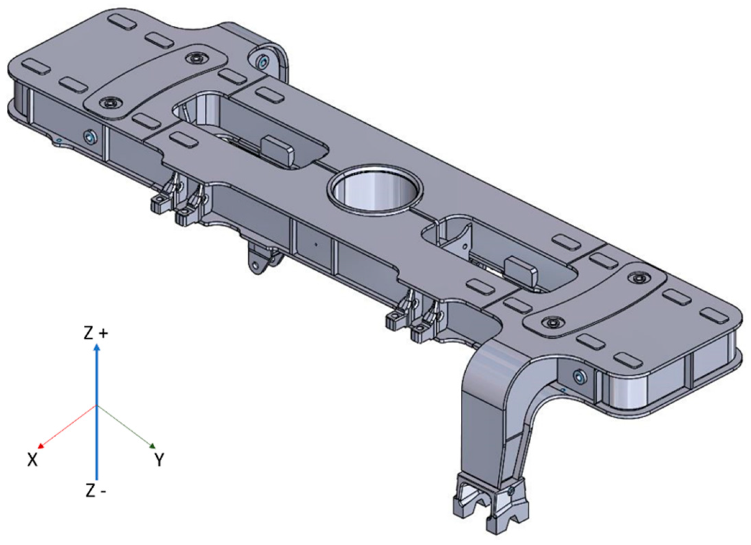
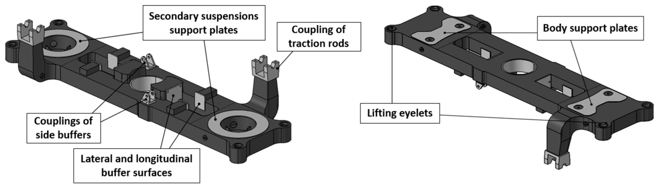
2.1. Model Description: The Bolster Beam
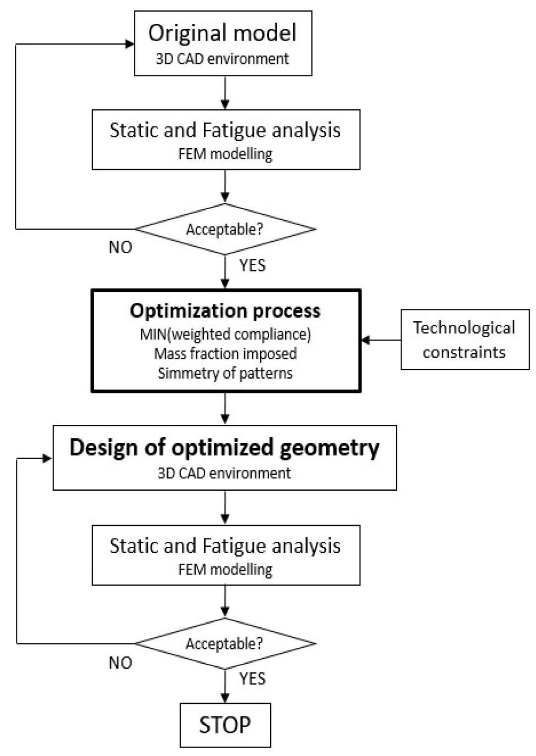
The structure of the original bolster beam, illustrated in Figure 1, was totally made with construction steel and assembled through welding. It was mounted on a tram vehicle, as a linking component between the bogie frame and the carbody. It was connected to the bogie systems through the two arms, while the main interfaces with the carbody were the two upper buffers and the central traction pin.
As previously mentioned, due to spatial constraints, the two tanks for pneumatic suspensions were positioned within the bolster beam. This solution reduces the complexity of the geometry while ensuring the desired volume. Another important characteristic was the presence of internal reinforcements, that allowed the component to be stiffer and support better bending loads. The torsional behavior was naturally good thanks to the box shape of the component. The original model served as a reference for generating the CAD model used in the optimization process. This model had all available space filled with material to maximize the workspace for the optimization solver while ensuring no interference with other vehicle components. To improve the optimization process and the subsequent redesign of the part, before making the mesh, the model was divided into two regions: design space (black color) and non-design space (gray color), as shown in Figure 2. The first one represented the volume of material that can be altered by the software. It must be maximized to give more freedom to the solver. The non-design space was minimized to only include the interfaces between the body and bogie components, ensuring non-interference and maintaining essential structural connections.
The next step was the generation of the grid. To optimize the number of nodes and elements, their size was adapted to different regions of the bolster, ranging from a minimum of 2.5 mm at the inner cylinders of the tanks to 10 mm for the central body of the structure. For the modeling of the reinforcement ribs inside the tanks, 5 mm elements were used, ensuring a minimum of two elements in the thickness of each geometric feature. To improve the quality of the tetra elements, automatic refinement functions were applied near the edges and fillets. For the support plates of the secondary suspensions and support plates of the body, instead, it was possible to use PENTA elements to reduce their number in those regions that would have required a much finer size of tetra elements. To apply the loads, 1D elements of type RBE3 were used, which prevented the structure from stiffening excessively. The model consisted of 1,073,078 elements and 1,782,362 nodes. To perform the optimization, the class 400 spheroidal graphite cast iron (EN-GJS-450-10) has been considered. This material has good mechanical performances with sufficient strain at breakage (10% minimum), ensuring good performance in terms of mechanical fatigue behavior. More precisely, the material presented an ultimate tensile stress (σu) of 450 MPa and yield stress (σY) of 310 MPa with a Young’s module (E) equal to 169,000 MPa. The steel with which it was compared (S355 construction steel), on the other hand, exhibited the following characteristics: ultimate tensile stress (σu) of 510 MPa and yield stress (σY) of 355 MPa with a Young’s module (E) equal to 210,000 MPa.

2.2. Methodology

The methodology proposed in the present activity aimed to combine CAD and FEM techniques with a structural optimization approach, whose settings were oriented to a casting manufacturing process. All simulations were conducted using the same computer that had the following characteristics: Intel(R) Xeon(R) CPU E5-2643 v4 @ 3.40GHz, RAM 32GB. Two manufacturing constraints have been introduced in the optimization procedure to evaluate the differences between the geometries proposed by the optimization process: “Extraction direction from a mold” and “Minimum feature size” are their reference names. Starting from the CAD model of the component, a detailed FE model was built and tested according to the reference standard EN 13749:2021 [26] with the aim to know the original mechanical behavior of the system.
In detail, 16 load cases have been considered to examine the mechanical performances in different running conditions. This phase has a key importance in the methodology proposed because it could lead to a better comprehension of the mechanical behavior of the structure in its original form. Furthermore, it would not have made sense to optimize a structure that does not support the loads acting on its original configuration After selecting the main interfaces with other vehicle systems, the model was prepared for the topological optimization process by defining the design and non-design spaces. The original model featured a welded, box-shaped structure with all available space filled with material to maximize the optimization solver workspace. Initially, the extreme zones, which functioned as tanks for the vehicle secondary pneumatic suspension, were included. This choice was fundamental to evaluate the internal structural reinforcements of the original configuration, which could generate major complications for the subsequent casting process. When all the volume of the model was defined, the design and non-design space were separated, maintaining the correct interfaces previously found. The optimization process had the objective of minimizing the weighted compliance, calculated on all the main load cases, including static and dynamic ones. As a constraint condition, a limit on the volume fraction has been imposed, as described within the next sections. In addition, three other types of constraints were included: symmetry with respect to the Z-axis, and two technological conditions closely related to casting manufacturing process (“Extraction direction from a mold” and “Minimum feature size”). The first one was imposed to the solver to remove material only in one direction, starting from a reference plane defined by the user, exactly as a piece is extracted from its mold at the end of the casting process. In order to ensure the correct performance of the casting process, the second constraint related to the minimal feature dimension has been imposed. This parameter impacts on the material flow within the mold. A tight flow section could slow down the melted material, leading to the generation of imperfections or localized cooling, which is representative of a non-excellent melting process. In this way, the optimization result could have the minimum size to guarantee the flow of the molten metal in the mold. Once the optimization step was completed, the new geometry was imported in a 3D CAD environment and modeled again. The redesigned bolster beam was then imported in commercial FE software for testing it again according to the reference conditions and to verify its mechanical performances. The overall process is summarized in Figure 3.

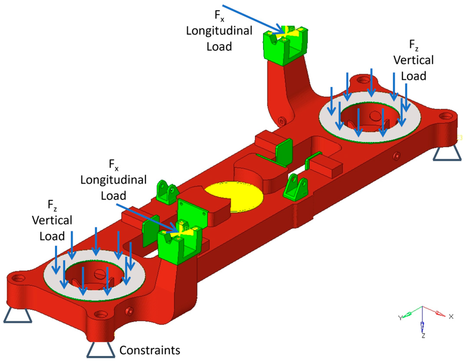
2.3. Optimization Settings and Load Cases

With the objective of evaluating the effect of the casting constraints, defined as “Extraction direction from a mold” and “Minimum feature size”, two types of optimization processes have been considered. In both cases, a gradient-based optimization method [27] has been adopted for solving the optimization problem. In Case 1, the manufacturing constraints were not imposed. This approach allowed the solver maximum freedom to perform the optimization within the design space. Conversely, in Case 2, manufacturing constraints were imposed. This ensured that the solver produced a result feasible for the casting process. For the second case, two alternatives were considered with different extraction directions: the first one with the extraction direction along the Z-positive direction and the second along the Z-negative direction. To run the optimization, other general settings, common to the three cases, were imposed to the solver. In detail, the optimization objective was to minimize the weighted compliance considering all the load cases introduced in the model and described below. As optimization constraint, the mass fraction, which is the ratio between the final and the initial mass of the design space, was set below 40%. Similarly, the imposition of a symmetry constraint was considered relevant, as the load cases were highly asymmetric. Then, a revolution symmetry was imposed around the Z-axis passing through the central hole of the beam. The main challenges regarding the definition of the optimization settings were the definition of the “Minimum feature size” and the symmetry constraint above described. Numerous tests were needed to find the suitable value for the studied geometry, allowing to achieve the correct level of detail in the optimized geometry. Once identified, it sped up the times in reconstructing the final design of the bolster beam. Table 1 shows the common settings for both test cases and the proposed technological constraints.
Case 1 has been studied as a reference to evaluate the effect of the manufacturing constraints. For Case 2, a main direction of extraction from the mold was imposed: along the positive Z-axis (openings upwards—Case 2a) and along the negative Z-axis (openings downwards—Case 2b). This latter setting was fundamental, because it allowed a simpler process for the creation of the mold. The ability to control the optimization process by incorporating casting properties will enable the adoption of casting for railway components, thereby eliminating critical features such as welds. Additionally, the casting process can reduce the need for extensive inspections and tests typically required for welded components. The load conditions contained in the technical specification, and considered in the optimization, were based on the EN 13749. Other load conditions have been indicated by the producer to ensure the quality and the reliability of the component. Inertial accelerations on the masses attached to the considered part have been defined according to the reference regulation. Overall, 16 load cases have been tested, taking into account some conditions that could occur during the operation and the maintenance of the vehicle (Figure 4). Particularly, we considered the following loads:
  • Longitudinal load on the bogie bolster to carbody connection;
  • Transversal load on the bogie bolster to carbody connection;
  • Truck lifting;
  • Truck twist (with also the completing unloading of one wheel);
  • Braking forces;
  • Internal pressure of the air springs;
  • Longitudinal lozenging forces.

3. Topological Optimization and FEA Results

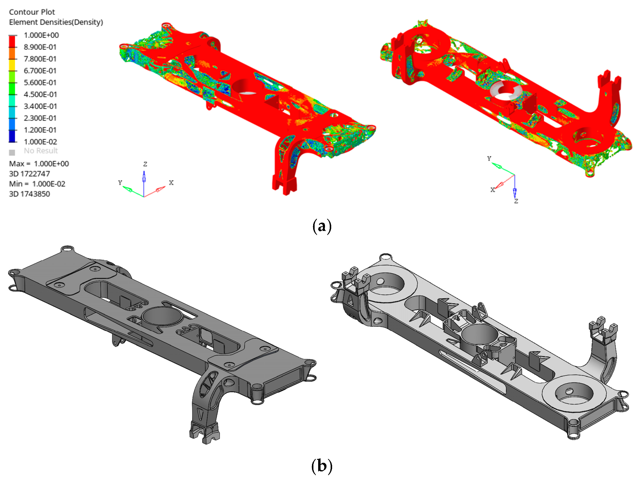
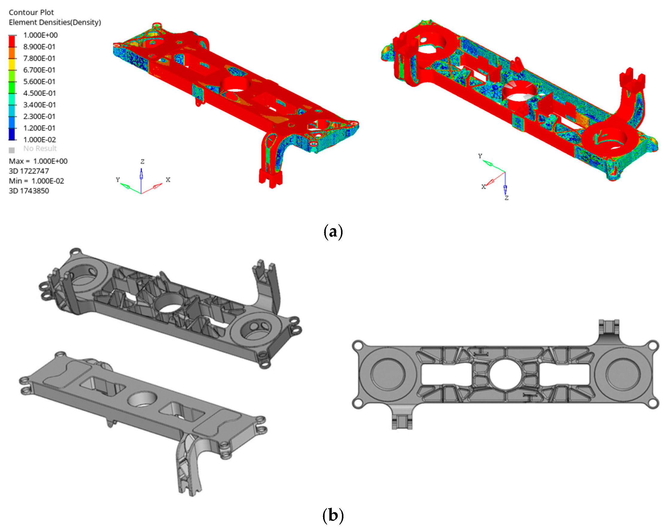
3.1. Topological Optimization Results

Since the first results obtained with the optimization process, it could be seen that Case 1 has a box-shaped geometry similar to that of the original bolster beam. Case 2a, with extraction direction from a mold constraint along the Z-positive direction, presented some openings upwards. This result could generate problems during the use of the vehicle due to the possibility of the accumulation of liquids or other impurities that degrade the structure, compromising its resistance. The result of Case 2b, with the extraction direction from a mold constraint along the Z-negative direction, on the other hand, allowed to solve this problem and was therefore considered more relevant than the previous one. For these reasons, the most relevant test cases, Case 1 and Case 2b, will be analyzed.

3.1.1. Topology Optimization Results—Case 1

In the first case, the geometry was similar to a box shape, with several lightening holes in the central area, on the arms of the connections for the traction rods and in the area around the tanks (Figure 5a). In the area of the arms, the ribs were reduced, and the material was removed, creating some holes on the outer surfaces. These considerations could reduce the mass of the optimized geometry without compromising the stiffness of the structure. It should be noted that the shape of Case 1 could only be produced using the welding process. After a visual assessment of the optimization results, the geometry, in STEP format, has been exported from the FE software to be imported into a commercial CAD software to perform reconstruction. The geometry was formed by an uneven set of surfaces and therefore could not be used directly for optimized bolster modeling. The bogie bolster was then completely redesigned, taking advantage of the original geometry and coherently with the results provided by the optimizer. Preliminary static analysis on the original model was therefore important for paying attention to the more stressed zone of the component during the redesign phase. The constraints due to the presence of joints to the bogie and to the train carbody were considered to allow the replacement of the new geometry in the assembly. Once the new geometry was ready, the numerical verification analyses on it were carried out considering all the design load cases. This phase was necessary to eliminate possible stress concentrations in a more detailed modeling step and to evaluate the modification introduced in the model. The average size of the elements was 8 mm, while in correspondence with smaller geometrical characteristics, a minimum size of 4 mm was adopted. These values were achievable thanks to the introduction of the Minimum feature size constraint. The main stress concentrations were observed at the fillet between the center of the bolster and the lateral dampers. It should be noted that the concentrations that occur on the structure were very localized and required detailed changes in the geometry. In particular, the geometry of the lateral dampers was modified by taking as reference the geometry of the original bogie bolster provided by the manufacturer, which showed the same distribution. Some holes were realized in this stress concentration zone, eliminating the connection between the lateral damper and the boxed top plate. The idea behind this modeling was to move the point of stress concentration in an area with more resistant material, which was effective, as shown in the following section.

3.1.2. Topology Optimization—Case 2

The effect of the technological constraint was clear: an opened shape was generated for most of the bolster beam, removing material along only a main direction. Instead, in correspondence of the connections for the lateral dampers, a sort of box structure was obtained. This region had to be modified in an opportune way to produce it without the necessity of casting cores. Similar to the previous case, some lightning holes were opened around the air tanks and on the arms for the traction rods. Figure 6a illustrates the optimization result for this step of the analysis. The obtained model had an upper region formed by a plate on which reinforcement ribs were placed to ensure the bending strength of the structure, trying to reduce the mass as much as possible. In the area around the secondary suspension link, the tanks were rebuilt with an appropriate volume. To manufacture this part, casting cores were necessary, particularly for components like the arms. Generally, the casting process necessitated minimizing elements in the undercut areas. When undercuts were unavoidable, specific cores had to be employed and properly connected to the mold. Verification analyses were carried out maintaining all the conditions of the previous step. Some localized stress concentrations were observed at the reinforcement ribs of the lateral and longitudinal dampers and at the connection arms with the traction rods. Then, the geometry of the reinforcement ribs was modified, increasing their dimensions in the critical areas. After a detailed mesh sensitivity analysis, an average element size of approximately 10 mm was achieved. Once again, the effect of the Minimum feature size constraint made the geometry reconstruction process faster and easier, ensuring an optimum detail of the FE model.
From a technological point of view, the fillet radii were increased to avoid excessive dimensional variations, reducing possible defects in the pouring phase of the cast iron within the mold. Regarding the concentrations around the connection arms with the traction rods, the fillet radius was increased, and at the same time, the dimensions of the reinforcements in this part were revised, following the optimization results. In addition, the symmetry of the beam was restored to ensure the resistance of the structure. The final design could be manufactured with casting techniques, achieving the main objective of the activity.

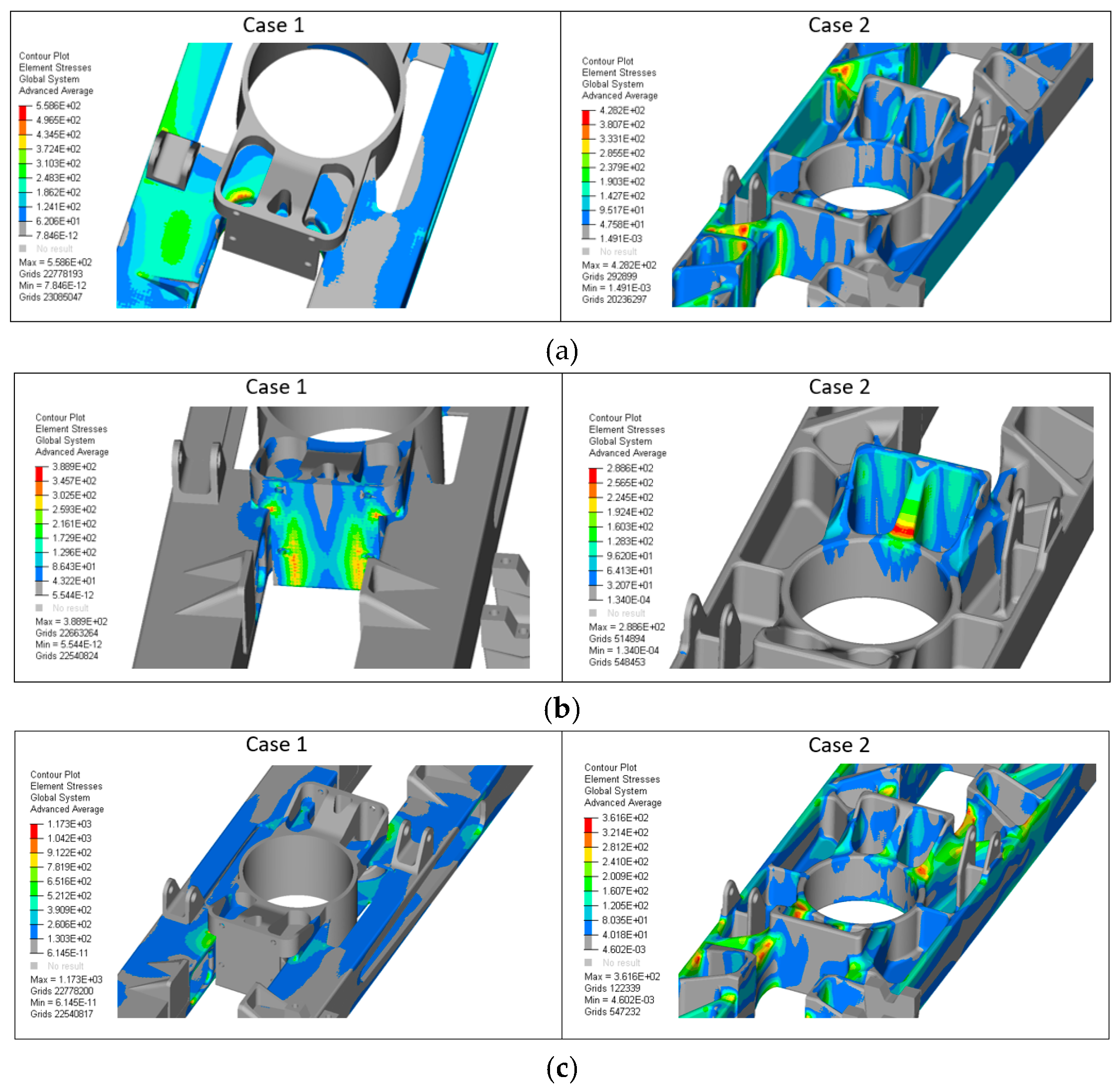
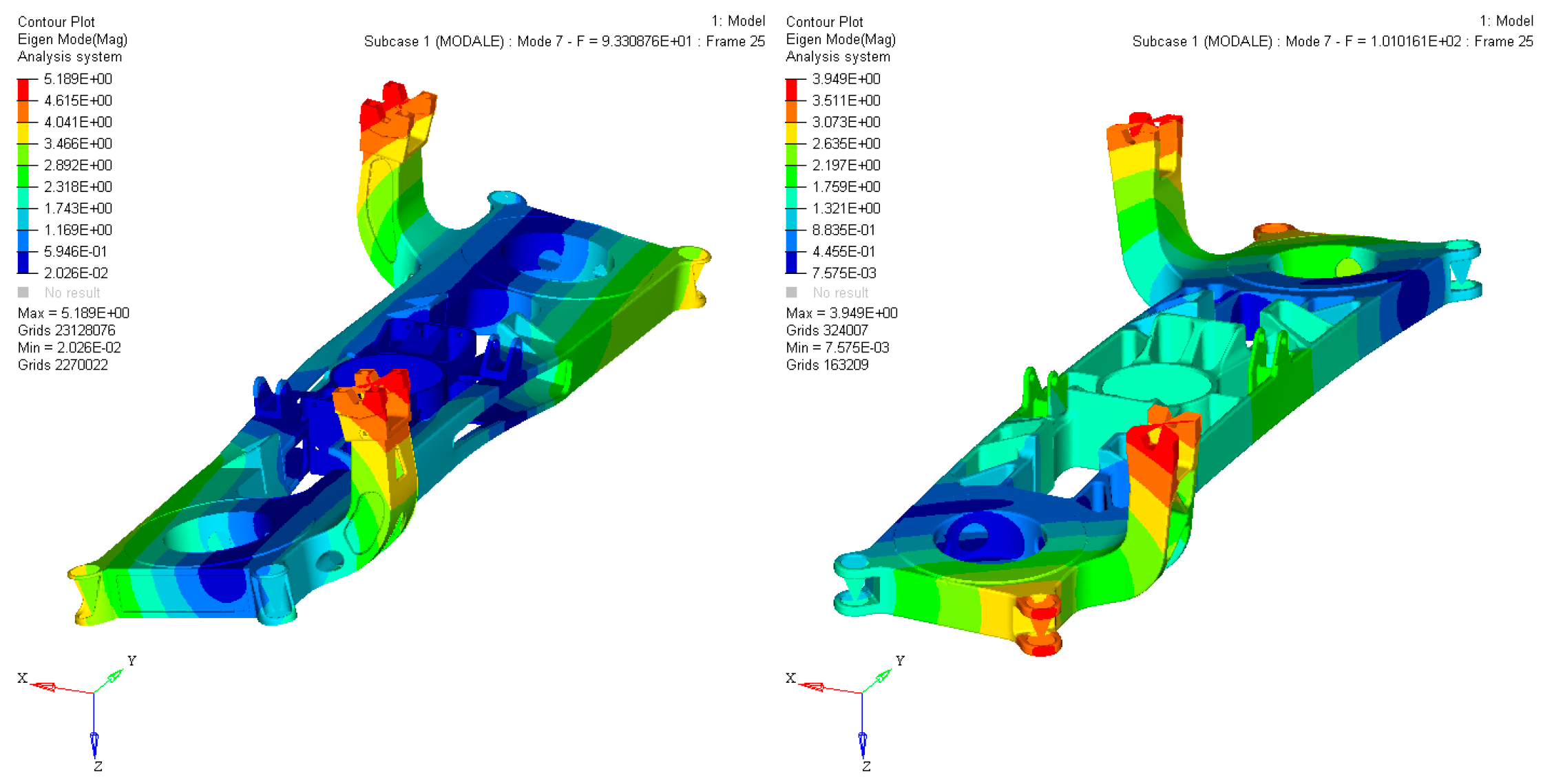
3.2. FEA Verification Results

To conclude the redesign of the bogie bolster beam, static analyses were carried out on the optimized structures. To do this, the design load cases have been considered, as previously seen. The same procedure seen for the previous analyses has been followed, and no changes have been made to the material introduced in the FE software. Below, we reported the most significant results of the simulations for the two geometries proposed. Three different load cases have been described: these conditions were the most critical for the resistance of the structure due to the high stresses generated. In addition, the information obtained from these cases was considered relevant for future activities in detailed design. FE analyses, according to EN 13749, and extremely localized stress concentrations will be assessed in future activity supported by experimental activities carried out by the manufacturer. The longitudinal load case was focused on the truck-to-carbody connection. The longitudinal force was applied partially on the traction rod ends and partially on longitudinal bumper plates. As expected, the main stress concentrations were in the regions near the lateral bumpers and on the reinforcement ribs behind the longitudinal bumper plates. Case 2 showed lower stress due to its innovative design as illustrated in Figure 7a. The transversal force, instead, was applied on the lateral bumper plate along the Y-positive direction. The main stress concentrations were localized near the lateral bumper plate. In detail, for Case 1, the critical regions were on the plate and near the small fillet between the plate and the lateral reinforcement ribs. Regarding Case 2, a stress concentration was detected on the reinforcement rib behind the lateral bumper plate, complying with the permissible value of the material (see Figure 7b). Finally, the lifting load case represented the truck lifting applied on only two eyelets to simulate the non-correct connection of the jacking system to the geometry. The bolster beam, during the lifting operations, had to resist the normal lifting load with a safety factor equal to two. The static analyses conducted on lifting conditions are generally the most critical. Case 1 showed a higher maximum value in a really localized area. The innovative design, instead, was able to distribute better the stress, reducing the stress level on the structure. Figure 7c illustrates the results for this load case. The plasticity effect in localized zones must be evaluated with a non-linear FE analysis.

4. Results and Discussion

In this section, the comparison between the two solutions is presented from a static and dynamic point of view. In Table 2, the maximum stress values have been summarized for the three load cases reported before. The table reports the “Utilization coefficient” to evaluate stress concentration, which is calculated as the ratio between maximum stress calculated and permissible stress. The maximum allowed value in the linear field is generally equal to 1. However, as in the case under consideration, local exceedances of stresses are permitted, considering the plastic behavior that characterizes metallic materials. In this case, although not required in this research activity, it is possible to proceed with a non-linear calculation. Significantly lower material utilization coefficients can be observed in Case 2, which is producible by casting, ranging from 25% to 70%.
In Case 1, the obtained model was formed by a box-shaped closed geometry with some reinforcement ribs inside it. For its realization, the use of the welding process will be necessary, similar to the original case. This solution had a lower mass compared with the existing bolster produced by the manufacturer (−17.7%), even if the complexity of the production of the component remained unchanged. In Case 2, the bolster beam was entirely manufacturable by casting due to the introduction of the extraction constraint from the mold during the optimization phase. Another advantage was that the welding inspection steps were no longer required. However, the mass of the component in this case was higher than in the original case (+9.0%). In terms of dynamic behavior, modal analysis carried out in free-free conditions has shown higher frequencies of vibration for the bolster beam feasible through sand casting with an increase of about 8% on the first one. This result was not a given, considering the greater mass. In addition, the nature of the first mode shape was changed: a first torsional mode was observed in Case 1, while a first flexural node with a double-nodal line was observed in Case 2. Figure 8 shows the mode shapes comparison.

5. Conclusions and Future Developments

In the present work, a structural topological optimization procedure combined with manufacturing constraints has been presented. Two different optimization procedures have been carried out on a railway bolster beam, and the use of spheroidal graphite cast iron has been examined. The two solutions were the result of optimization with different technological constraints that allowed obtaining geometric features for the specific production process. The problems of topological optimization were formulated to minimize the weighted compliance considering both static and fatigue load cases. The first solution (Case 1) has allowed to design a lighter bolster beam, maintaining a box-shaped geometry. The component needed to be produced using a welding-supported process, thus retaining many of the initial component’s critical aspects. The second solution (Case 2), as a result of the proposed optimization procedure, has revealed the potential to quickly redesign the geometry of a component that conforms to the requirements of the casting process. Moreover, it led to a stiffer design. Imposing constraints related to the extraction direction from the mold and minimum feature size could facilitate a transition to entirely different manufacturing processes and geometries. This research emphasizes the necessity of continuing to explore optimization procedures within the railway industry. These procedures hold the potential for achieving mass reduction, guiding design innovations, and streamlining production processes. Additionally, integrating fatigue optimization techniques with finite element (FE) analysis, particularly when dealing with time-varying load cases, promises a higher level of precision compared to the capabilities offered by the currently employed FE software. This convergence could mark the inception of a new era in railway component design and validation. The adoption of these innovative methodologies has the capacity to yield substantial advantages within the railway field.

Author Contributions

Conceptualization, methodology, software and validation A.C.; review, supervision, project administration E.M. and A.R. All authors have read and agreed to the published version of the manuscript.

Funding

This research received no external funding.

Institutional Review Board Statement

Not applicable.

Informed Consent Statement

Not applicable.

Data Availability Statement

The original contributions presented in the study are included in the article, further inquiries can be directed to the corresponding author.

Acknowledgments

This study was supported by MOST Sustainable Mobility National Research Center and received funding from the European Union Next GenerationEU (PIANO NAZIONALE DI RIPRESA E RESILIENZA (PNRR) MISSIONE 4 COMPONENTE 2, INVESTIMENTO 1.4 D.D. 1033 17 June 2022, CN00000023).

Conflicts of Interest

The authors declare no conflicts of interest.

References

  1. Wang, Y.; Kang, Z. Structural shape and topology optimization of cast parts using level set method: Structural shape and topology optimization of cast parts using level set method. Int. J. Numer. Meth. Eng. 2017, 111, 1252–1273. [Google Scholar] [CrossRef]
  2. Allaire, G.; Jouve, F.; Michailidis, G. Casting Constraints in Structural Optimization via a Level-Set Method. Orlando, United States. 2013, p. 10. Available online: https://hal.science/hal-01088775 (accessed on 28 May 2024).
  3. Xia, Q.; Shi, T.; Wang, M.Y.; Liu, S. A level set based method for the optimization of cast part. Struct. Multidisc. Optim. 2010, 41, 735–747. [Google Scholar] [CrossRef]
  4. Xia, Q.; Shi, T.; Wang, M.Y.; Liu, S. Simultaneous optimization of cast part and parting direction using level set method. Struct. Multidisc. Optim. 2011, 44, 751–759. [Google Scholar] [CrossRef]
  5. Liu, J.; Ma, Y. A survey of manufacturing oriented topology optimization methods. Adv. Eng. Softw. 2016, 100, 161–175. [Google Scholar] [CrossRef]
  6. Gersborg, A.R.; Andreasen, C.S. An explicit parameterization for casting constraints in gradient driven topology optimization. Struct. Multidisc. Optim. 2011, 44, 875–881. [Google Scholar] [CrossRef]
  7. Liu, S.; Li, Q.; Chen, W.; Hu, R.; Tong, L. H-DGTP—A Heaviside-function based directional growth topology parameterization for design optimization of stiffener layout and height of thin-walled structures. Struct. Multidisc. Optim. 2015, 52, 903–913. [Google Scholar] [CrossRef]
  8. Guest, J.K.; Prévost, J.H.; Belytschko, T. Achieving minimum length scale in topology optimization using nodal design variables and projection functions. Int. J. Numer. Meth. Eng. 2004, 61, 238–254. [Google Scholar] [CrossRef]
  9. Schmitt, O.; Friederich, J.; Riehl, S.; Steinmann, P. On the formulation and implementation of geometric and manufacturing constraints in node–based shape optimization. Struct. Multidisc. Optim. 2016, 53, 881–892. [Google Scholar] [CrossRef]
  10. Harzheim, L.; Graf, G. A review of optimization of cast parts using topology optimization: I—Topology optimization without manufacturing constraints. Struct. Multidisc. Optim. 2005, 30, 491–497. [Google Scholar] [CrossRef]
  11. Bhosale, G.H.; Sapkal, S.U. Re-engineering of Cast Product by Topology Optimization. IJETER 2021, 9, 1211–1216. [Google Scholar]
  12. Luo, Y.; Peng, Y. Topology optimization design of the suspension arm of a certain type of train battery system. JMESS 2021, 7, 4059–4061. [Google Scholar]
  13. Hoosain, S.E.; Tshabalala, L.; Bester, D.; Chetty, D.; Mukwevho, G. Additive Manufacturing Case Study in the Railway Industry; Rapid Product Development Association of South Africa: Pretoria, South Africa, 2020. [Google Scholar]
  14. Koenig, J. Integral Consideration of the Lightweight Design for Railway Vehicles; Technical University of Denmark: Lyngby, Denmark, 2011. [Google Scholar]
  15. Cascino, A.; Meli, E.; Rindi, A. Dynamic size optimization approach to support railway carbody lightweight design process. Proc. Inst. Mech. Eng. Part F: J. Rail Rapid Transit 2023, 237, 871–881. [Google Scholar] [CrossRef]
  16. Cascino, A.; Meli, E.; Rindi, A. A strategy for lightweight designing of a railway vehicle car body including composite material and dynamic structural optimization. Rail. Eng. Sci. 2023, 31, 340–350. [Google Scholar] [CrossRef]
  17. Kirkayak, L.; Krüger, D.; Malzacher, G.; Gomes Alves, C.; Schmauder, N.; Kopp, G. Lightweight Design Concept Methodology of the Extended Market Wagon: A Shift2Rail Project; WCRR: Birmingham, UK, 2022; p. 6. [Google Scholar]
  18. Li, X.; Peng, F.; Yang, Z.; Peng, Y.; Zhou, J. Structural optimization design of a bolster based on simulation driven design method. Transp. Saf. Environ. 2023, 5, tdac075. [Google Scholar] [CrossRef]
  19. Srivastava, P.K.; Shukla, S. Topology Optimization: Weight Reduction of Indian Railway Freight Bogie Side Frame. Int. J. Mech. Eng. 2021, 6, 4374–4383. [Google Scholar]
  20. Park, B.H.; Lee, K.Y. Bogie frame design in consideration of fatigue strength and weight reduction. Proc. Inst. Mech. Eng. Part F J. Rail Rapid Transit. 2006, 220, 201–206. [Google Scholar] [CrossRef]
  21. Krishnakumar, K. Micro-Genetic Algorithms For Stationary And Non-Stationary Function Optimization. In Intelligent Control and Adaptive Systems; Rodriguez, G., Ed.; SPIE: Bellingham, WA, USA, 1990; pp. 289–296. [Google Scholar]
  22. Park, B.H.; Kim, N.P.; Kim, J.S.; Lee, K.Y. Optimum design of tilting bogie frame in consideration of fatigue strength and weight. Veh. Syst. Dyn. 2006, 44, 887–901. [Google Scholar] [CrossRef]
  23. Yamamoto, M. Non-parametric optimization of railway wheel web shape based on fatigue design criteria. Int. J. Fatigue 2020, 134, 105463. [Google Scholar] [CrossRef]
  24. Abid, M. Analysis and Redesign of Bolster Beam of the Bogie Frame of a Locomotive. J. Eng. Res. 2013, 1, 271–287. [Google Scholar]
  25. Cetin, M.H.; Alvali, G.T.; Korkmaz, S. Parameter Optimization with Multi-criteria Decision-Making Methods in Rail Transport: A Case Study of Freight Wagon Bogie. Arab. J. Sci. Eng. 2021, 46, 10059–10076. [Google Scholar] [CrossRef]
  26. EN 13749:2021; Railway Applications—Wheelsets and Bogies—Method of Specifying the Structural Requirements of Bogie Frames. iTeh, Inc.: Newark, DE, USA, 2021.
  27. Jameson, A. Gradient Based Optimization Methods; MAE Technical Report No (2057); Princeton University: Princeton, NJ, USA, 1995. [Google Scholar]
Figure 1. View of the original bolster beam.
Eng 05 00079 g001
Figure 2. Design space (black) and non-design space regions (gray).
Eng 05 00079 g002
Figure 3. Scheme of the redesign procedure, including optimization process.
Eng 05 00079 g003
Figure 4. Example of a longitudinal load case condition.
Eng 05 00079 g004
Figure 5. Case 1: (a) result of the optimization, element density distribution; (b) final geometry of the redesigned bolster beam.
Eng 05 00079 g005
Figure 6. Case 2: (a) result of the optimization, element density distribution; (b) final geometry of the redesigned bolster beam.
Eng 05 00079 g006
Figure 7. Stress distribution in Case 1 vs. Case 2: (a) longitudinal load case, (b) transversal load case, (c) lifting load case.
Eng 05 00079 g007
Figure 8. First mode shapes comparison: Case 1 vs. Case 2.
Eng 05 00079 g008
Table 1. Optimization settings.
ParametersCase 1Case 2aCase 2b
General settingsMaterialSpheroidal graphite cast iron EN-GJS-450-10
Symmetry constraintCyclic around Z axis
Optimization constraintMass fraction < 0.4
Optimization objectiveMin. weighted compliance
Load cases consideredStatic and fatigue
Technological constraintsExtraction from mold-Z positiveZ negative
Minimum feature size-20 mm20 mm
Table 2. Performance comparison between the two optimized geometries.
Load Case σ a m m [MPa]Case 1Case 2
σ m a x [MPa]U [-] σ m a x [MPa]U [-]
Longitudinal3105591.804281.38
Transversal3901.262890.93
Lifting11733.783621.17
σ m a x is the maximum stress evaluated through FE analysis, σ a m m is permissible stress, U is the utilization coefficient.
Disclaimer/Publisher’s Note: The statements, opinions and data contained in all publications are solely those of the individual author(s) and contributor(s) and not of MDPI and/or the editor(s). MDPI and/or the editor(s) disclaim responsibility for any injury to people or property resulting from any ideas, methods, instructions or products referred to in the content.

