Article

Metal-Hydride-Based Hydrogen Storage as Potential Heat Source for the Cold Start of PEM FC in Hydrogen-Powered Coaches: A Comparative Study of Various Materials and Thermal Management Techniques

Centre for Advanced Low Carbon Propulsion Systems (C-ALPS), Coventry University, Priory Street, Coventry CV1 5FB, UK
*
Author to whom correspondence should be addressed.
Hydrogen 2022, 3(4), 418-432; https://doi.org/10.3390/hydrogen3040026
Submission received: 26 September 2022 / Revised: 13 October 2022 / Accepted: 26 October 2022 / Published: 1 November 2022

Abstract

:
The successful and fast start-up of proton exchange membrane fuel cells (PEMFCs) at subfreezing temperatures (cold start) is very important for the use of PEMFCs as energy sources for automotive applications. The effective thermal management of PEMFCs is of major importance. When hydrogen is stored in hydride-forming intermetallics, significant amounts of heat are released due to the exothermic nature of the reaction. This excess of heat can potentially be used for PEMFC thermal management and to accelerate the cold start. In the current work, this possibility is extensively studied. Three hydride-forming intermetallics are introduced and their hydrogenation behavior is evaluated. In addition, five thermal management scenarios of the metal hydride beds are studied in order to enhance the kinetics of the hydrogenation. The optimum combination of the intermetallic, hydrogenation behavior, weight and complexity of the thermal management system was chosen for the study of thermal coupling with the PEMFCs. A 1D GT-SUITE model was built to stimulate the thermal coupling of a 100 kW fuel cell stack with the metal hydride. The results show that the use of the heat from the metal hydride system was able to reduce the cold start by up to 8.2%.

1. Introduction

Proton exchange membrane Fuel cells (PEMFCs) are devices in which oxygen and hydrogen electrochemically react to generate electricity and heat, and the by-product is water [1,2]. Although the efficiency of a PEMFC is relatively high (up to 55%), the amount of heat generated from the reaction is large [3,4]; thus, the produced heat must be effectively removed from the PEMFC to maintain the temperature at the desirable operational levels (below 60 °C) [5,6].
PEMFCs usually operate at relatively low temperatures, usually in the range of 60–80 °C [7], which makes this type of fuel cell a suitable option for many stationary and mobile applications, where a quick start-up is particularly essential [8]. The heat generated during the operation of PEM fuel cells can be extracted and used in a range of heating applications (e.g., hot water supply, space heating, or heating up the inlet reactants in cold climate conditions), together with the power generated by the fuel cell.
The solid-state hydrogen storage in metallic materials with the formation of metal hydrides is an effective way to store hydrogen, as most of the materials used for the storage operate under moderate temperature and pressure conditions [8,9,10]. The process of hydrogen uptake from the materials is an exothermic process, with large amounts of heat produced [11,12]. The materials’ temperature during the storage naturally tends to increase and, due to the low thermal conductivity of the metal hydride powders, the temperature remains at high levels [13]. The temperature increase negatively affects the kinetics of the hydrogenation process [14] as the higher temperature also increases the equilibrium pressure Peq. As the Peq reaches higher values, the ratio of p/Peq, where p is the hydrogen pressure, decreases. This ratio is the driving force for the hydrogen storage in metal hydrides and, consequently, decelerates the storage. Thus, effective ways to remove the produced heat and maintain the kinetics of the reaction fast is necessary [15,16,17]. The dehydrogenation process proceeds in the opposite direction, where the hydrogen release from the metal lattice is an endothermic process, in order to force the bonds between the hydrogen and the metal atoms from the lattice to break and release the hydrogen [18]. Due to the low thermal conductivity of the metal hydride powder, ensuring a homogeneous distribution of the heat is challenging; thus, hydrogen is released at different rates from various parts of the hydride [19,20]. Additionally, in this case, effective thermal management is crucial to ensure a homogeneous temperature distribution within the hydride [21]. Some of the parameters governing the thermodynamic performance of metal hydrides are the (specific) enthalpy of the formation (during the hydrogenation process) or the deformation (during the dehydrogenation process) ΔH [kJ/kmol], the specific heat capacity of the hydride Cp [kJ/kmol/K], the thermal conductivity λ [W/mK], the hysteresis and the slope [22]. There are mainly two heat management techniques that have been widely applied to enhance the heat transfer to/from the metal hydride tank, namely internal heat management and external heat transfer [23]. The major focus to improve heat transfer in a metal hydride bed should be on the reduction in the metal hydride thickness [24], the increase in thermal conductivity [25] and the introduction of a large temperature difference [26].
The hydrogen storage to metal hydrides is an exothermic process. The produced heat during hydrogenation needs to be removed from the hydride to keep the kinetics of the reaction fast. In addition, this thermal energy can be used to feed a PEMFC for the cold start. The normal operation of PEMFCs requires a constant supply of fuel and oxidants, as well as the drainage of the produced water [27]. In subfreezing temperatures, the water produced can freeze in the porous layers, even at the flow channels. The ice blocks the gas transport and potentially covers the catalyst reaction sites: this is expected to cause start-up failures. Then, the thermal coupling between the PEMFC and metal hydrides and the utilization of the produced heat of the hydrogen storage to assist the cold start of the PEMFCs is a potential technique, especially for automotive applications of large vehicles, such as coaches, trains and ships.
In the current work, the thermal coupling between various metal hydrides and a 100 kW fuel cell stack has been studied and evaluated. The first stage of this work focuses on the identification of the optimum conditions and the materials for the solid-state hydrogen storage. Various metal hydrides are introduced and their performance during hydrogen storage is evaluated. In addition, five scenarios regarding the thermal management of metal hydride tanks have been studied, and the optimum metal hydride, along with the proper thermal management, were selected for the thermal coupling with the PEMFC. The second stage of this work considers the study of the thermal coupling between the metal hydride bed and the PEMFC. A one-dimensional GT-SUITE model was developed to simulate the thermal management of a fuel cell stack, along with the metal hydride, and it was found that the combination of the optimum metal hydride with the PRMFC can reduce the cold start by 8.2%.

2. Methodology

In the current study, the heat, mass and momentum conservation equations were solved simultaneously using a commercial Multiphysics package (COMSOL Multiphysics 5.5, Stockholm, Sweden) [28]. The proposed numerical model was validated against solid experimental data (hydrogen storage capacity and temperature) extracted from a lab-scale Sievert-type apparatus. The expansion of packed beds during the hydrogenation process can produce additional stress to the vessel walls; therefore, the hydride beds were assumed to be 50% full at the beginning of the hydrogenation process.

2.1. Tank Geometries and Thermal Management Scenarios

The target of the present work is to study the hydrogenation process of various hydride-forming intermetallic compounds when the amount of hydrogen stored/released per cycle is 100 g (equivalent energy is 12 MJ, based on a gravimetric energy density of 120 MJ/kg [29]). The metal hydride tanks were of a cylindrical shape. The cylindrical metal hydride tanks were chosen to own the same properties of stainless steel (316SS) and the wall thickness of the tanks was 3 mm, which is similar to commercially available cylindrical tanks. In general, there are two main thermal management techniques applied to enhance the heat transfer from metal hydride beds, namely internal and external thermal management [30]. According to Fourier’s law of conduction, there are three main ways to enhance the heat transfer within the operating hydride beds: the reduction in the metal hydride thickness [31]; the enhancement of the thermal conductivity [32]; and the introduction of a temperature difference ΔΤ [33]. In the current study, the heat transfer mechanism was a combination of convection and conduction. This can be achieved by the introduction of embedded cooling tubes in the metal hydride tank, where a coolant is used to pass through the tubes and remove the produced heat. For this reason, for real-life applications, either chillers or pumps are used to control the temperature and flow rate of the coolant. Figure 1 illustrates all the thermal management scenarios introduced and studied for the metal hydride beds. The baseline scenario (Scenario 1) represents the introduction of four embedded cooling tubes, one central tube and three tubes placed co-centrally (Figure 1a), whereas the introduction of six co-central tubes comprise the second thermal management scenario (Figure 1b). In order to achieve a more homogeneous temperature distribution, a spiral tube was also considered (Figure 1c–e), in which various heating cooling tubes were added (1–4 and 8, respectively). The radius of the embedded cooling tubes was 0.005 m, the radius of the metal hydride bed was 0.0517 m and the length of the tank and the tubes were 0.5 m. The spiral coil was selected to have 17.2 turns, with a major radius of 0.048 m and an axial pitch of 0.03 m. Table 1 presents the details of all the thermal management scenarios, including the total active surface area for the heat transfer of each case.
More detail on the geometries used is presented in Figure S1 in the Supplementary Materials.

2.2. Numerical Model

2.2.1. Assumptions of the Numerical Model

The use of metal hydrides for solid-state hydrogen storage is a rather complex procedure that involves chemical reactions, diffusion and heat transfer phenomena. For that reason, in order to simplify the numerical analysis, several assumptions were made and are listed as follows:
(a)
The medium is in a local thermal equilibrium, which implies that there is no heat transfer between solid and gas phases.
(b)
The temperature and pressure profiles are initially uniform.
(c)
Hydrogen is treated as an ideal gas from a thermodynamic point of view. This is an assumption that sometimes might be far from the reality and might affect the accuracy of the model. In case the hydrogen pressure is below 20 bar and room temperature, this is, in general, an acceptable assumption supported by the literature [34,35,36]. However, this assumption must not be made when the pressure of the system is higher. For the analysis of a hydride-based hydrogen compressor, the compressibility factor must be considered when the density of the gas is calculated and updated [15]. Just for the comparison, the compressibility factor for a pressure of 20 bar, temperature of 10 °C and 100 g H2 is Z = 1.079804 whereas for pressure of 300 bar (middle stage for a 700 bar compressor) the compressibility factor is Z = 1.25 [37]. (The compressibility factor for ideal gas is 1.)
(d)
Thermal conductivity and specific heat capacity are assumed to be constant.
(e)
The porosity remains constant and uniform during hydrogenation.
(f)
The characteristics (the kinetics and thermal properties) of the bed are unaffected by the number of loading and unloading cycles. Thus, bed aging is neglected.
(g)
The metal hydride bed fills the entire space between the cooling tubes and the spiral heat exchanger (perfect packing condition).

2.2.2. Heat Equation

Assuming thermal equilibrium between the hydride powder and hydrogen gas, a single heat equation can be solved, instead of separate equations for solid and gas phases:
( ρ · C p ) e f f · T t + ( ρ g + C p g + v g ) · T + · ( k e f f · T ) = Q H
The term QH (W/m3) in Equation (1) represents the heat that has been generated during the hydrogenation process. The amount of heat produced during the hydrogenation process depends on several thermophysical properties of the materials, such as the enthalpy of formation ΔH (J/mol), the porosity of the material ε, the density changes during the reaction (kg/m3), the reaction rate (1/s) and the molecular mass of the stored gas (kg/mol). The enthalpy of the hydride formation was measured experimentally from the isotherm curves during the hydrogenation of the intermetallics used in the current study, while the density change was calculated and updated with time from the concentration of the species using the Transport of Diluted Species module in COMSOL Multiphysics 5.5 [38].
The effective heat capacity is given by:
( ρ C p ) e = ε ρ g C p g + ( 1 ε ) ρ s C p s
and the effective thermal conductivity is updated by:
k e = ε k g + ( 1 ε ) k s
The terms ρg, Cpg, Cps and m refer to the density of the gas phase (kg/m3), the specific heat capacity of the gas phase (J/kg/K), the heat capacity of the solid phase and the kinetic term for the reaction, respectively. The parameter that represents the void fraction is symbolized by ε. The values for kg (W/m/K) and ks (W/m/K) represent the thermal conductivity for the gas and the solid-state, respectively. MH2 represents the molecular mass of hydrogen (kg/mol), and T represents the temperature (K).

2.2.3. Hydrogen Mass Balance

The diffusion of hydrogen gas within the metallic matrix is described by:
ε ( ρ g ) t + d i v ( ρ g v g ) = ± Q
where vg is the velocity of gas during diffusion within the metal lattice (described in Section 2.2.4), and Q (kg/m3s) is the mass source term describing the amount of hydrogen mass diffused per unit time and unit volume in the metal lattice [9,15].

2.2.4. Momentum Equation

By neglecting the gravitational effect, the equation that describes the velocity of gas inside the metal matrix is:
v g = K μ g g r a d ( P g )
where K (m2) is the permeability of the solid, μg (Pa s) is the dynamic viscosity of gas and Pg (kPa) is the pressure of gas within the metal matrix.

2.2.5. Hydrogenation Kinetic Expression

The kinetic description for the hydrogenation process per unit time and volume is updated by:
m a = C a · exp [ E a R g · T ] · ln [ p g P e q ] · ( ρ s s ρ s )
where Ea (J/mol) is the activation energy for the hydrogenation process and Ca (1/s) is the pre-exponential constant. Finally, Pg (Pa) is the pressure of hydrogen during hydrogenation and Peq (Pa) is the equilibrium pressure (presented in Section 2.2.6).

2.2.6. Equilibrium Pressure

To incorporate and consider the effect of hysteresis and the plateau slope on the calculation of the plateau pressure Peq, the following equation was used [39]:
ln P e q 10 5 = { [ Δ H R T Δ S R ] + ( φ s ± φ 0 ) tan [ π ( x x s a t 1 2 ) ] ± S 2 }
The plateau slope is given by flatness factors φs and φ0, and S represents the hysteresis effect, which is given by (lnPabs/Pdes). Hydrogenation is denoted by ‘+’ and dehydrogenation is denoted by ‘−’, while x and xsat are the local hydride concentration at any given time and saturation, respectively. For all the studied materials, the flatness factors and the hysteresis effects were measured experimentally using the data collected from the hydrogenation kinetics and isotherms.

3. Validation of the Numerical Model

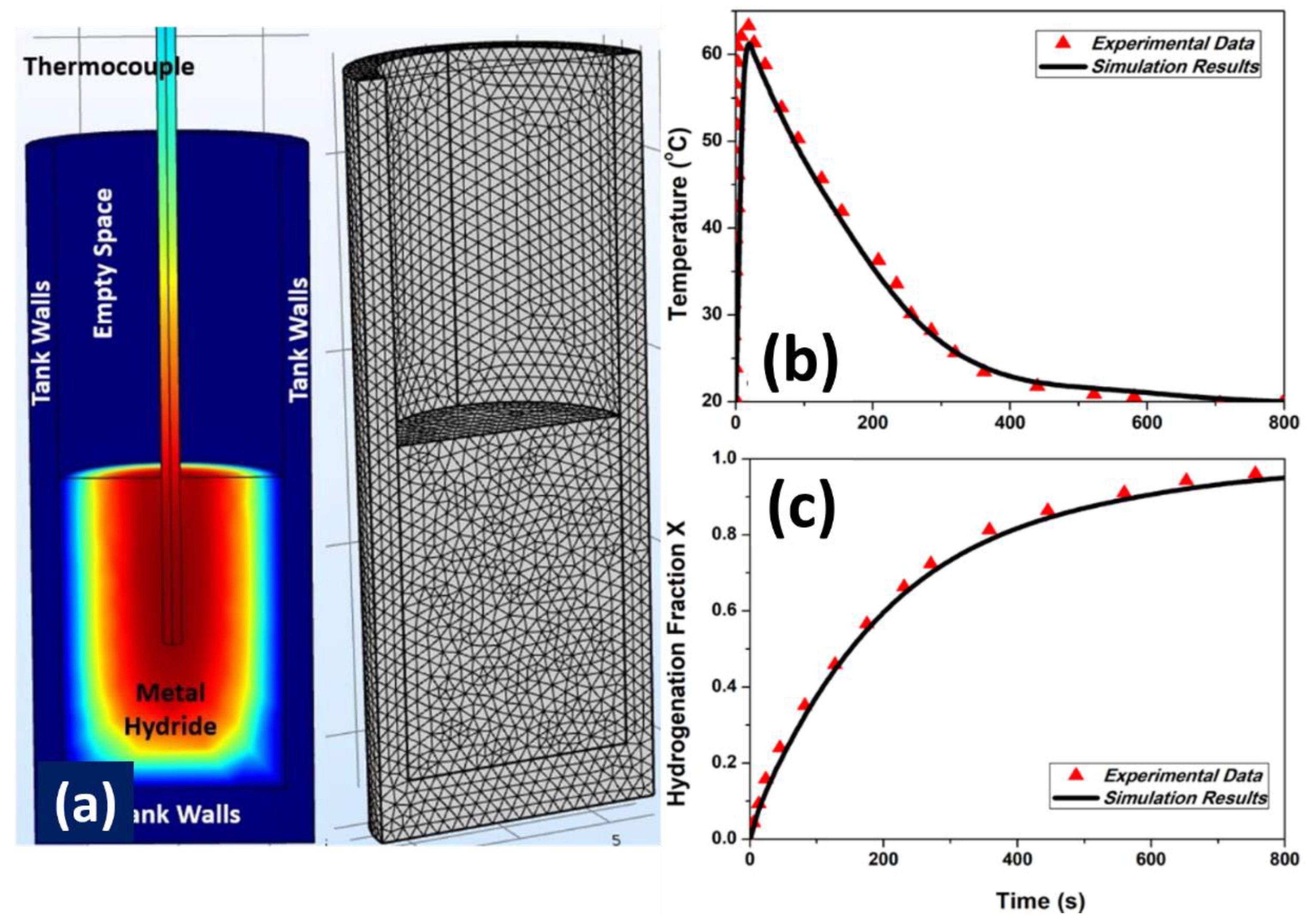
The validation of the proposed numerical model was conducted against experimental data extracted from a commercial Sievert-type apparatus (HIDEN Isochema-IMI Instruments, Manchester, UK). Both the hydrogenation and temperature behavior of the material were extracted during the charging process at an initial hydrogen supply pressure of 15 bar and at a temperature of 20 °C. The amount of material tested was 1 g. Figure 2a shows the geometry of the bed used for the validation of the numerical model and the position of the thermocouple. Figure 2b shows the comparison of the temperature profile during the hydrogenation process and Figure 2c shows the hydrogenation profile of the material. The results of the numerical work compared to the experimental data present good agreement with a maximum deviation of no more than 5%.

4. Results and Discussion

4.1. Temperature Distribution and Hydrogenation Kinetics

Hydrogenation kinetics are very important for effective hydrogen storage. The kinetics of the hydrogen storage are described by the charging time tc. The charging time (tc) is defined as the time needed for the hydrogenation ratio to increase from 0.1 to 0.9. The hydrogenation ratio is the ratio between the amount of hydrogen stored and the maximum theoretical amount of hydrogen that the specific material is able to store reversibly. To improve the hydrogenation kinetics, five thermal management scenarios of the metal hydride bed were introduced and studied. The geometries of the five scenarios are described in Figure 1. In addition, three different hydride-forming intermetallic compounds were studied under the same scenarios. The materials used in the current study are a ‘conventional’ LaNi5 intermetallic, an AB5-type MmNiAl intermetallic and an AB2 Laves-phase Zr-Ti-Fe-Cr-Mn intermetallic. Table 2 presents the main properties of the materials used in this study.
Figure 3a presents the temperature profile of the AB2 intermetallic during the hydrogenation process for all the heat management scenarios studied. The initial temperature of the bed and the coolant was 10 °C and the hydrogen supply pressure was 20 bar. The temperature at the beginning of the hydrogenation process increased due to the highly exothermic process and reached a maximum value. After that point, the thermal management began to dominate, and the temperature dropped as it tends to reach the temperature of the coolant. In this case, the maximum temperature achieved during the hydrogenation process was between 75–78 °C for all scenarios. The temperature profile of the hydride heavily affects the hydrogenation kinetics. In general, the hydrogenation process takes place in two steps. During the first step, the hydrogenation rate increases rapidly due to the large pressure difference between the hydrogen pressure and the equilibrium pressure. This pressure difference is the driving potential for hydrogen absorption in the metal lattice.
The temperature at the beginning of the process was at the maximum value (75–78 °C), during the first 40–60 s of the reaction. This is due to the low thermal conductivity of the hydride powders that restrict effective heat removal. During that period, the hydride stores an amount of hydrogen at a hydrogenation fraction of X = 0.13 (Figure 3b) (13% of the theoretical maximum amount of hydrogen that can be stored). During this step, the pressure difference is the major factor in hydrogen storage. However, the temperature increase results in the increase in equilibrium pressure; thus, the driving potential for the hydrogenation decreases. During the second stage of hydrogenation, the circulating coolant removes the produced heat from the tank and gradually reduces the temperature. As a result, the driving potential increases and the hydrogen storage continues. This process continues until the maximum capacity is achieved. Figure 3b presents the hydrogenation fraction for all thermal management scenarios. For all the scenarios (except Scenario 3), the hydrogenation fraction reaches X = 0.9 (90% of the maximum theoretical amount of hydrogen stored) in less than 1500 s. Scenario 5 presents the fastest hydrogenation kinetics, and this is further supported by the temperature profile, in which the temperature of the hydride drops faster than the rest of the scenarios. The charging time tc for Scenarios 5, 2, 4 and 1 is 890 s, 1070 s, 1250 s and 1340 s, respectively. The other two materials that were used in this work (LaNi5 and the Mm-based AB5 intermetallic) presented similar thermal and hydrogenation behavior (Figure S2, supplementary material).
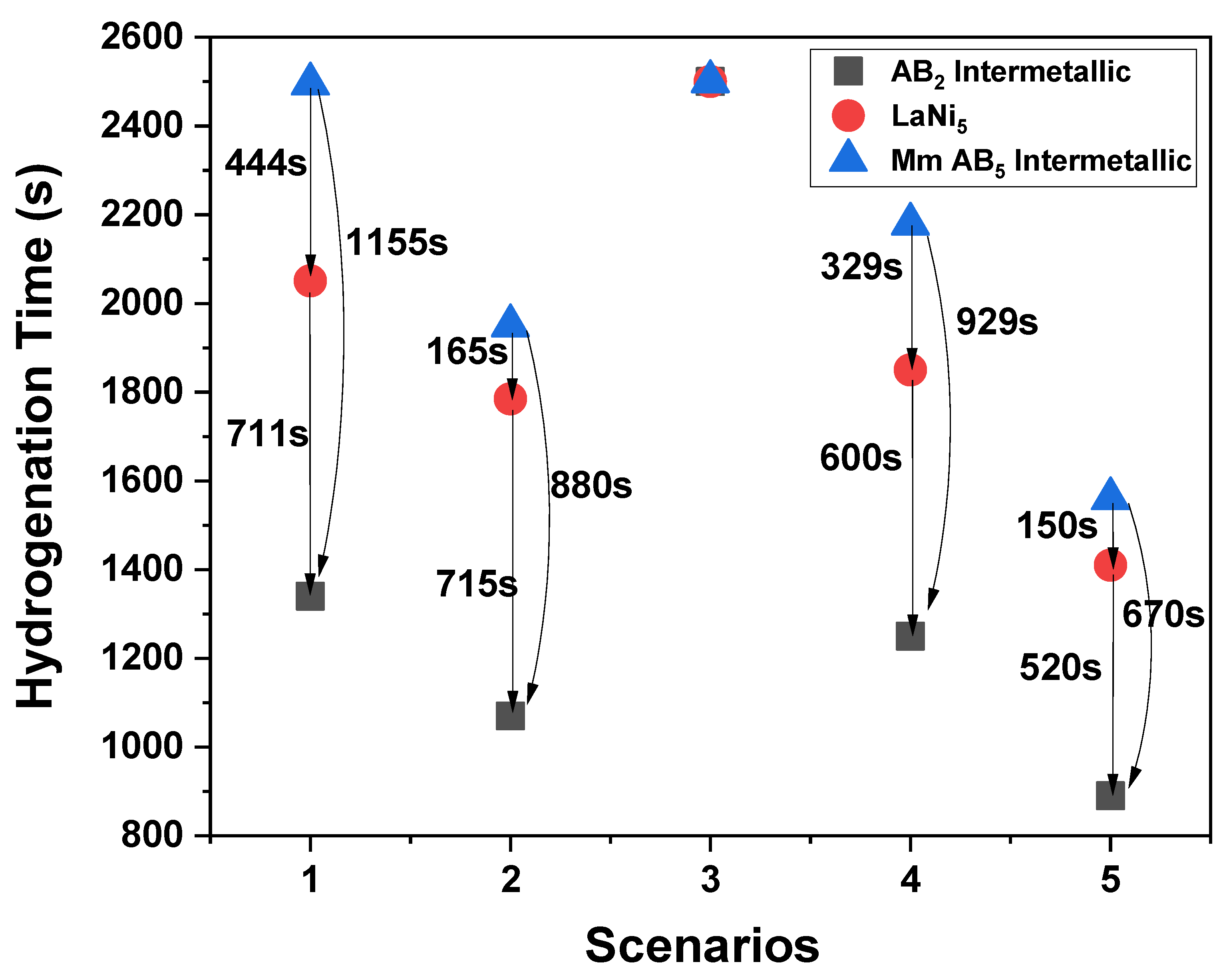
Table 3 presents the charging time (tc) of all the materials studied for all thermal management scenarios. The thermal management technique used for Scenario 3 was not able to effectively remove the produced heat, and the hydrogenation kinetics were slow (tc more than 2500 s).
Figure 4 presents a comparison of all the thermal management scenarios studied and the different materials used in terms of the charging time (tc). It can be extracted that all the materials behave in a similar way for each thermal management scenario. Scenario 5 seems to provide a more efficient heat removal during hydrogenation as, for all the materials studied, it provides the fastest kinetics. The thermal management scenario suggested in Scenario 3 appears to not remove the produced thermal energy effectively from the metal hydride bed; thus, the kinetics are slow, and all the materials studied did not reach X = 0.9 within 2500 s.
For practical applications, such as the thermal coupling of a metal hydride bed with an operating PEMFC, and besides the thermal and hydrogen storage response of the hydride, the total weight of the system (metal hydride, metal hydride cylinder, thermal management geometry) is also crucial, especially for automotive applications. Table 4 presents the total weight of the system for every scenario studied.
From the analysis conducted, it can be concluded that for all the hydrides used in the current study, two scenarios are the most efficient, namely Scenario 2 and Scenario 5. Scenario 2 involves the introduction of six embedded cooling tubes, one in the center of the reactor and the remaining five tubes distributed co-centrally. Scenario 5 includes six cooling tubes in a similar way to Scenario 2, but a spiral heat exchanger was also introduced to ensure the homogeneity of the temperature distribution of the hydride close to the cylinder walls. Figure 5 shows the comparison between these two scenarios only and between the charging time needed to reach X = 0.9, as well as the total weight of the system, for all the three materials used. For both scenarios, the utilization of the AB2 intermetallic resulted in the best combination of performance and total weight. For the thermal coupling analysis between the metal hydrides and the PEMFCs, both scenarios are taken into account when the metal hydride is the AB2 intermetallic.

4.2. Thermal Coupling of the Metal Hydride and the PEMFC

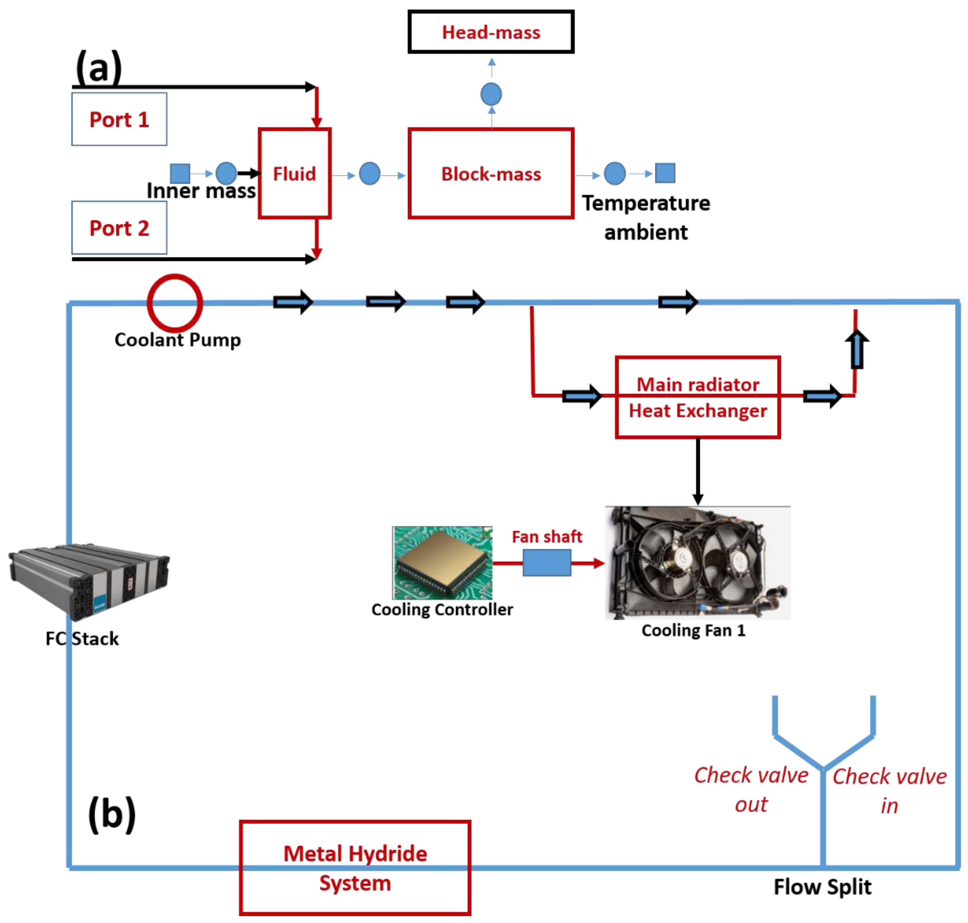
A 1D GT-SUITE model was developed to simulate the thermal management of a fuel cell stack and thermal coupling with metal hydride tanks when they are charged with hydrogen. The main target in this case was to drive the produced heart during hydrogenation (exothermic process) to the operating fuel cell during the first minutes of operation. Figure 6a shows the layout of the thermal management system. A Ballard FCmove HD + 100 FC module (100 kW) was used in this study as the FC stack. Figure 6b shows the fuel cell model in the GT-SUITE model.
Table 5 lists the FC stack settings used in the study. A default template, namely “Engine Block with three Masses”, was used to model the coolant within the FC, as well as the FC structure. This object simplifies the cooling passage into a single fluid volume. The fuel cell structure is represented by three thermal masses. One of these masses is an “inner” mass that is connected only to the fluid volume and receives direct heat input (heat generation by the cells operating in the stack). The fluid is then connected to the “outer” masses that represent the stack hardware (‘block’) and endplates (‘head-mass’). The outer masses can transfer heat to the ambient environment. In addition, the initial temperature for the PEMFC, the coolant and the environment is − 5 °C. In the current study, the cold start time was defined as the time necessary for the PEMFC to reach 65 °C.
Figure 7 presents the PEMFC temperature when it was thermally coupled with the operating metal hydride system. The AB2 intermetallic was selected as the operating hydride under two thermal management scenarios (Scenario 2 and 5). For comparison purposes, LaNi5 operating under Scenario 5 was included in the analysis. The coolant, when entering the metal hydride, was 10 °C and the coolant at the outlet of the metal hydride system was higher. Therefore, this was the main reason for the rapid increase in PEMFC temperature during the first 50 s of the operation (Figure 7b). After that time, the rate of increase was lower as the temperature difference decreased. The usage of the metal hydride system to assist and enhance the cold start time seems to positively affect the PEMFC temperature and reduce the cold start time. Table 6 shows the cold start time for all the cases studied.
The selection of the AB2 intermetallic under both Scenario 2 and 5 were able to reduce the cold start time by 7.23 and 8.19%, respectively, whereas the selection of LaNi5 reduced the time only by 4.49%. In addition, the difference in the performance of the AB2 intermetallic in the two scenarios (2 and 5) was small (6 s). The total weight of the hydride system was 11.16 kg and 10.85 kg for Scenario 5 and Scenario 2, respectively. Finally, the thermal management system for Scenario 2 was less complex than the system for Scenario 5, as it did not involve the installation of the cooling coil. For automotive applications, the total weight of the system is of major importance for the proper selection of the metal hydride system. However, in the case of the thermal management of a PEMFC that will operate in a coach, the small difference between Scenario 5 and 2 (310 g) will not affect the total weight of the total system. However, in this case, Scenario 2 is less complex compared to Scenario 5, with a very close performance in the thermal management of the PEMFC. Consequently, the selection of the AB2 intermetallic operating under Scenario 2 seems the best option to enhance the cold start performance of the PEMFC.

5. Conclusions

In the current study, the introduction of metal hydrides and their effect on the cold start of a PEMFC, when they are thermally coupled, has been investigated. The main target of the current work was to study the effect of the excess heat that is produced during the hydrogenation process on the cold start of a PEM fuel cell stack. The main idea was to thermally couple the operating metal hydride bed and to drive the heat during the exothermic hydrogenation process to the PEMFC stack, in order to accelerate the operation of the PEMFC for hydrogen-powered coaches. Three hydride-forming intermetallics were tested for that purpose. The properties of the intermetallics were experimentally extracted and imported in commercial software (COMSOL Multiphysics 5.5). The hydrogenation process of each intermetallic depends on various thermodynamic parameters, such as the enthalpy/entropy of hydride formation, the thermal conductivity and the specific heat capacity. In addition, as the thermal conductivity of the hydride powders is small, to accelerate the hydrogenation, thermal management is preferable to effectively remove the produced heat. Thus, five different thermal management scenarios for the metal hydride beds were introduced and studied. The most promising combinations of the metal hydride/thermal management scenario were selected. This selection was based mainly in three factors: the hydrogenation kinetics; the hydrogenation thermal response; and the total weight/complexity of the thermal management system. It was found that the combination of the AB2 intermetallic and a thermal management scenario, involving six embedded cooling tubes and a co-centrally placed spiral coil, presented the best performance, whereas the combination of the AB2 intermetallic and a thermal management scenario, involving six embedded cooling tubes without the coil, also presented a promising performance. However, based on the less complexity and (potential) cost of the spiral coil, it was concluded that the thermal management scenario without the coil might be more applicable. The next step was the study of the thermal coupling of the operating metal hydride bed with the PEMFC stack. A Ballard FCmove HD + 100 FC module was used in this study as the FC stack. It was found that the introduction and use of the metal hydride system to enhance the cold start time can positively affect the PEMFC operation and reduce the cold start time by up to 8.2%. Future plans include studying the effect of installing phase change materials (PCMs) in the system, along with metal hydride beds, and to evaluate the total performance of the system.

Supplementary Materials

The following supporting information can be downloaded at: https://www.mdpi.com/article/10.3390/hydrogen3040026/s1, Figure S1: Extra information about the tank design geometries that have been used in this study; Figure S2. Temperature and hydrogenation behavior for LaNi5 (S2(a, b) respectively) and for the AB5 Mm-Intermetallic (S2(c, d) respectively).

Author Contributions

Conceptualization, E.I.G., C.W., S.S., O.C. Methodology, E.I.G., C.W. Software, E.I.G., C.W. Data Curation E.I.G. Validation, E.I.G. Investigation, E.I.G., C.W. Writing-original draft preparation, E.I.G. Writing, Review and Editing, E.I.G. Visualization, E.I.G. Funding Acquisition, O.C., S.S. All authors have read and agreed to the published version of the manuscript.

Funding

This research was funded by the CoacHyfied project. The project has received funding from the Fuel Cells and Hydrogen 2 Joint Undertaking (now Clean Hydrogen Partnership) under Grant Agreement No. 101006774. This Joint Undertaking receives support from the European Union’s Horizon 2020 Research and Innovation program, Hydrogen Europe and Hydrogen Europe Research.

Conflicts of Interest

The authors declare no conflict of interest.

References

  1. Meyer, Q.; Ashton, S.; Curnick, O.; Reisch, T.; Adcock, P.; Ronaszegi, K.; Robinson, J.B.; Brett, D.J.L. Dead-Ended Anode Polymer Electrolyte Fuel Cell Stack Operation Investigated Using Electrochemical Impedance Spectroscopy, off-Gas Analysis and Thermal Imaging. J. Power Sources 2014, 254, 1–9. [Google Scholar] [CrossRef]
  2. Khzouz, M.; Gkanas, E.I.; Shao, J.; Sher, F.; Beherskyi, D.; El-Kharouf, A.; Al Qubeissi, M. Life Cycle Costing Analysis: Tools and Applications for Determining Hydrogen Production Cost for Fuel Cell Vehicle Technology. Energies 2020, 13, 3783. [Google Scholar] [CrossRef]
  3. Nishimura, A.; Toyoda, K.; Mishima, D.; Ito, S.; Hu, E. Numerical Analysis on Impact of Thickness of PEM and GDL with and without MPL on Coupling Phenomena in PEFC Operated at Higher Temperature Such as 363 K and 373 K. Energies 2022, 15, 5936. [Google Scholar] [CrossRef]
  4. Tawalbeh, M.; Alarab, S.; Al-Othman, A.; Javed, R.M.N. The Operating Parameters, Structural Composition, and Fuel Sustainability Aspects of PEM Fuel Cells: A Mini Review. Fuels 2022, 3, 449–474. [Google Scholar] [CrossRef]
  5. D’Souza, C.; Apicella, M.; El-kharouf, A.; Stamatakis, E.; Khzouz, M.; Stubos, A.; Gkanas, E.I. Thermal Characteristics of an Air-Cooled Open-Cathode Proton Exchange Membrane Fuel Cell Stack via Numerical Investigation. Int. J. Energy Res. 2020, 44, 11597–11613. [Google Scholar] [CrossRef]
  6. Nyamsi, S.N.; Tolj, I.; Gęca, M.J. Dehydrogenation of Metal Hydride Reactor-Phase Change Materials Coupled with Light-Duty Fuel Cell Vehicles. Energies 2022, 15, 2982. [Google Scholar] [CrossRef]
  7. Yang, Y.; Jia, H.; Liu, Z.; Bai, N.; Zhang, X.; Cao, T.; Zhang, J.; Zhao, P.; He, X. Overall and Local Effects of Operating Parameters on Water Management and Performance of Open-Cathode PEM Fuel Cells. Appl. Energy 2022, 315, 118978. [Google Scholar] [CrossRef]
  8. Gkanas, E.I. Metal Hydrides: Modeling of Metal Hydrides to Be Operated in a Fuel Cell. In Portable Hydrogen Energy Systems; Ferreira-Aparicio, P., Chaparro, A.M., Eds.; Academic Press: Cambridge, MA, USA, 2018; pp. 67–90. ISBN 978-0-12-813128-2. [Google Scholar]
  9. Gkanas, E.I.; Statheros, T.; Khzouz, M. Heat Management on Rectangular Metal Hydride Tanks for Green Building Applications. Int. J. Hydrogen Energy 2019, 44, 19267–19274. [Google Scholar] [CrossRef]
  10. Xu, Z.; Zhao, N.; Hillmansen, S.; Roberts, C.; Yan, Y. Techno-Economic Analysis of Hydrogen Storage Technologies for Railway Engineering: A Review. Energies 2022, 15, 6467. [Google Scholar] [CrossRef]
  11. Krane, P.; Nash, A.L.; Ziviani, D.; Braun, J.E.; Marconnet, A.M.; Jain, N. Dynamic Modeling and Control of a Two-Reactor Metal Hydride Energy Storage System. Appl. Energy 2022, 325, 119836. [Google Scholar] [CrossRef]
  12. Gkanas, E.I.; Damian, A.; Ioannidou, A.; Stoian, G.; Lupu, N.; Gjoka, M.; Makridis, S.S. Synthesis, Characterisation and Hydrogen Sorption Properties of Mechanically Alloyed Mg(Ni1-XMnx)2. Mater. Today Energy 2019, 13, 186–194. [Google Scholar] [CrossRef]
  13. Tan, J.; Chai, M.; He, K.; Chen, Y. Numerical Simulation on Heating Effects during Hydrogen Absorption in Metal Hydride Systems for Hydrogen Storage. Energies 2022, 15, 2673. [Google Scholar] [CrossRef]
  14. Malleswararao, K.; Dutta, P.; Murthy, S.S. Applications of Metal Hydride Based Thermal Systems: A Review. Appl. Therm. Eng. 2022, 215, 118816. [Google Scholar] [CrossRef]
  15. Gkanas, E.I.; Stamatakis, E.; Christodoulou, C.N.; Tzamalis, G.; Karagiorgis, G.; Chroneos, A.; Kuganathan, N.; Khzouz, M.; Stubos, A.K. Study on the Operation and Energy Demand of Dual-Stage Metal Hydride Hydrogen Compressors under Effective Thermal Management. Int. J. Hydrogen Energy 2021, 46, 29272–29287. [Google Scholar] [CrossRef]
  16. Gkanas, E.I.; Grant, D.M.; Stuart, A.D.; Eastwick, C.N.; Book, D.; Nayebossadri, S.; Pickering, L.; Walker, G.S. Numerical Study on a Two-Stage Metal Hydride Hydrogen Compression System. J. Alloys Compd. 2015, 645, S18–S22. [Google Scholar] [CrossRef]
  17. Lototskyy, M.; Linkov, V. Thermally Driven Hydrogen Compression Using Metal Hydrides. Int. J. Energy Res. 2022. [Google Scholar] [CrossRef]
  18. Luo, Y.; Wang, Q.; Li, J.; Xu, F.; Sun, L.; Zou, Y.; Chu, H.; Li, B.; Zhang, K. Enhanced Hydrogen Storage/Sensing of Metal Hydrides by Nanomodification. Mater. Today Nano 2020, 9, 100071. [Google Scholar] [CrossRef]
  19. Gkanas, E.I.; Khzouz, M.; Panagakos, G.; Statheros, T.; Mihalakakou, G.; Siasos, G.I.; Skodras, G.; Makridis, S.S. Hydrogenation Behavior in Rectangular Metal Hydride Tanks under Effective Heat Management Processes for Green Building Applications. Energy 2018, 142, 518–530. [Google Scholar] [CrossRef]
  20. Nguyen, H.Q.; Shabani, B. Review of Metal Hydride Hydrogen Storage Thermal Management for Use in the Fuel Cell Systems. Int. J. Hydrogen Energy 2021, 46, 31699–31726. [Google Scholar] [CrossRef]
  21. Keith, M.D.; Kukkapalli, V.K.; Kim, S. Phase Change Cooling of a Metal Hydride Reactor for Rapid Hydrogen Absorption. Energies 2022, 15, 2490. [Google Scholar] [CrossRef]
  22. Gkanas, E.I.; Makridis, S.S.; Stubos, A.K. Modeling and Simulation for Absorption-Desorption Cyclic Process on a Three-Stage Metal Hydride Hydrogen Compressor. Comput. Aided Chem. Eng. 2013, 32, 379–384. [Google Scholar] [CrossRef]
  23. MacDonald, B.D.; Rowe, A.M. Impacts of External Heat Transfer Enhancements on Metal Hydride Storage Tanks. Int. J. Hydrogen Energy 2006, 31, 1721–1731. [Google Scholar] [CrossRef]
  24. MacDonald, B.D.; Rowe, A.M. A Thermally Coupled Metal Hydride Hydrogen Storage and Fuel Cell System. J. Power Sources 2006, 161, 346–355. [Google Scholar] [CrossRef]
  25. Tong, L.; Xiao, J.; Bénard, P.; Chahine, R. Thermal Management of Metal Hydride Hydrogen Storage Reservoir Using Phase Change Materials. Int. J. Hydrogen Energy 2019, 44, 21055–21066. [Google Scholar] [CrossRef]
  26. Visaria, M.; Mudawar, I.; Pourpoint, T.; Kumar, S. Study of Heat Transfer and Kinetics Parameters Influencing the Design of Heat Exchangers for Hydrogen Storage in High-Pressure Metal Hydrides. Int. J. Heat Mass Transf. 2010, 53, 2229–2239. [Google Scholar] [CrossRef]
  27. Nishizaki, T.; Miyamoto, K.; Yoshida, K. Coefficients of Performance of Hydride Heat Pumps. J. Less-Common Met. 1983, 89, 559–566. [Google Scholar] [CrossRef]
  28. COMSOL. Multiphysics® v. 5.5; COMSOL: Stockholm, Sweden. Available online: www.comsol.com (accessed on 10 October 2022).
  29. Hydrogen Storage|Department of Energy; Office of Energy Efficiency and Renewable Energy: Washington, DC, USA, 2022.
  30. Anbarasu, S.; Muthukumar, P.; Mishra, S.C. Thermal modeling of LmNi4.91Sn0.15 based solid state hydrogen storage device with embedded cooling tubes. Int. J. Hydrogen Energy 2014, 39, 15549–15562. [Google Scholar] [CrossRef]
  31. Jemni, A. Study of two-dimensional heat and mass transfer during absorption in a metal-hydrogen reactor. Int. J. Hydrogen Energy 1995, 20, 43–52. [Google Scholar] [CrossRef]
  32. Rodriguez Sanchez, A.; Klein, H.P.; Groll, M. Expanded graphite as heat transfer matrix in metal hydride beds. Int. J. Hydrogen Energy 2003, 28, 515–527. [Google Scholar] [CrossRef]
  33. Laurencelle, F.; Goyette, J. Simulation of heat transfer in a metal hydride reactor with aluminium foam. Int. J. Hydrogen Energy 2007, 32, 2957–2964. [Google Scholar] [CrossRef]
  34. Chibani, A.; Merouani, S.; Bougriou, C.; Hamadi, L. Heat and Mass Transfer during the Storage of Hydrogen in LaNi5-Based Metal Hydride: 2D Simulation Results for a Large Scale, Multi-Pipes Fixed-Bed Reactor. Int. J. Heat Mass Transf. 2020, 147, 118939. [Google Scholar] [CrossRef]
  35. Jithu, P.V.; Mohan, G. Performance Simulation of Metal Hydride Based Helical Spring Actuators during Hydrogen Sorption. Int. J. Hydrogen Energy 2022, 47, 14942–14951. [Google Scholar] [CrossRef]
  36. Aadhithiyan, A.K.; Sreeraj, R.; Anbarasu, S. Thermal Modelling and Performance Evaluation of LmNi4.91Sn0.15 Hydride Bed Configurations for Space-Constrained Thermal Applications. Appl. Therm. Eng. 2022, 216, 119116. [Google Scholar] [CrossRef]
  37. Hirscher, M. Handbook of Hydrogen Storage: New Materials for Future Energy Storage; Wiley: Hoboken, NJ, USA, 2010. [Google Scholar]
  38. COMSOL. Multiphysics 5.5 Reference Manual; COMSOL Multiphysics® v. 5.5; COMSOL AB: Stockholm, Sweden, 2021; Chapter 12; p. 842. [Google Scholar]
  39. Gkanas, E.I.; Khzouz, M. Numerical Analysis of Candidate Materials for Multi-Stage Metal Hydride Hydrogen Compression Processes. Renew. Energy 2017, 111, 484–493. [Google Scholar] [CrossRef]
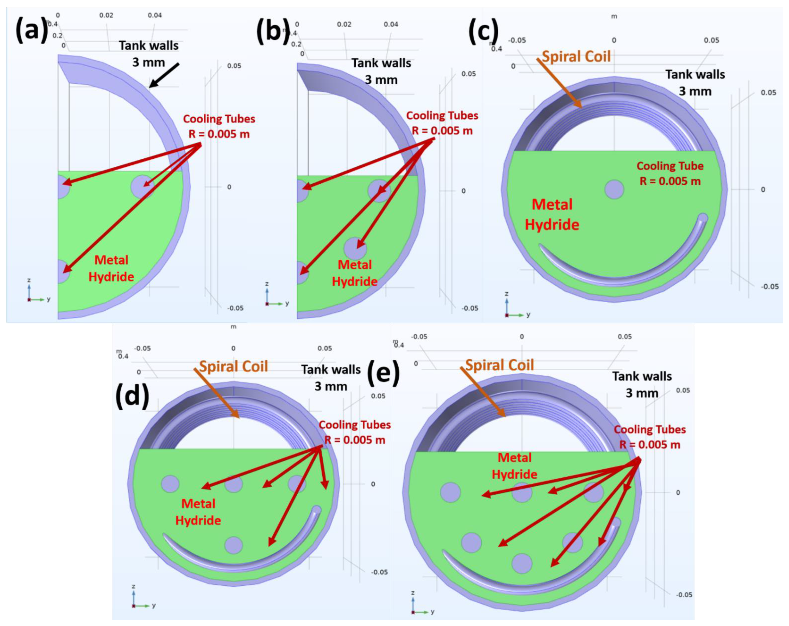
Figure 1. Tank design geometries: (a) is the base line scenario with four embedded cooling tubes; (b) has six cooling tubes. For a more homogeneous temperature distribution; (ce) include a spiral coil along with the embedded cooling tubes.
Hydrogen 03 00026 g001
Figure 2. Geometry used for the validation (a); (b,c) present the temperature and hydrogenation profile of the numerical data against the experimental data.
Hydrogen 03 00026 g002
Figure 3. (a) shows the bed temperature profile for all the thermal management scenarios when the AB2 intemetallic used as the metal hydride, and (b) shows the hydrogenation kinetics for all thermal management scenarios.
Hydrogen 03 00026 g003aHydrogen 03 00026 g003b
Figure 4. Comparison of the hydrogenation time for all scenarios and all materials studied.
Hydrogen 03 00026 g004
Figure 5. Comparison of the hydrogenation time and the total weight the system for Scenario 2 and 5.
Hydrogen 03 00026 g005
Figure 6. Illustration of the PEMFC model used for the 1D GT-SUITE model. (a) presents the layout of the thermal management system, whereas (b) presents the total Fuel Cell and management system as used in the GT-SUITE model.
Hydrogen 03 00026 g006
Figure 7. PEMFC temperature when it is thermally coupled with metal hydride. (a) presents the total temperature profile for all the 4 scenarios studied. For clarity, (b) shows the temperature profile for the first 100 s, (c) the profile between 100–400 s, (d) illustrates the temperature profile for last 200 s of the measurement (400–600 s).
Hydrogen 03 00026 g007
Table 1. Details of all the tank geometries used in the current study.
Thermal Management ScenarioNo Cooling TubesSpiral CoilTank Radius (m)Tank Length (m)Active Surface Area (m2)
Scenario 14No0.05170.50.0952
Scenario 26No0.05170.50.1269
Scenario 31Yes0.05170.50.1037
Scenario 44Yes0.05170.50.1671
Scenario 56Yes0.05170.50.2147
Table 2. Main properties of the metal hydrides.
PropertiesLaNi5Mm IntermetallicAB2 Intermetallic
Effective density (kg/m3)4175.03172.53250.0
Activation Energy (J/molH2)28,500.026,250.024,350.0
Enthalpy of formation (J/molH2)28,300.025,242.028,579.0
Entropy of formation (J/molH2/K)102.1105.1106.8
Molecular weight (g/mol)432.5435.2173.9
Table 3. Charging time of the materials studied for all the thermal management scenarios.
N/AAB2 Intermetallic ts (s)LaNi5 ts (s)Mm AB5 Intermetallic ts (s)
Scenario 1134020512495
Scenario 2107017851950
Scenario 3>2500>2500>2500
Scenario 4125018502179
Scenario 589014101560
Table 4. Total weight of the system for all the thermal management scenarios.
N/AAB2 Intermetallic
Total Mass (kg)
LaNi5
Total Mass (kg)
Mm AB5 Intermetallic
Total Mass (kg)
Scenario 110.5211.7911.73
Scenario 210.8512.1112.05
Scenario 310.3511.6111.56
Scenario 410.8312.1112.04
Scenario 511.1612.4212.36
Table 5. PEMFC stack settings used in the study.
ParameterUnitValue
Inner masskg175
Block masskg175
Head masskg67
Fluid volume in fuel cellL0.5
Heat transfer aream28
Convective heat transfer coeff.Wm−2K−11000
Area for external convection to ambientm21
Convective heat transfer coeff. to ambientWm−2K−150
Table 6. Cold start time for all the simulated cases.
CaseCold Start Time (s)Reduced Time (%)
No MH6230
AB2—Scenario 25787.23
AB2—Scenario 55728.19
LaNi5—Scenario 55954.49
Publisher’s Note: MDPI stays neutral with regard to jurisdictional claims in published maps and institutional affiliations.