Proceeding Paper

Comparative Investigation of Membrane Systems for Crystallization and Spherical Agglomeration †

by
Izabela Lackowska
,
Marijana Dragosavac
and
Brahim Benyahia
*
Chemical Engineering, School of AACME, S Building, Loughborough University, Epinal Way, Loughborough LE11 3TU, UK
*
Author to whom correspondence should be addressed.
Presented at the 3rd International Online Conference on Crystals, 15–30 January 2022; Available online: https://iocc_2022.sciforum.net/.
Chem. Proc. 2022, 9(1), 2; https://doi.org/10.3390/IOCC_2022-12162
Published: 15 January 2022
(This article belongs to the Proceedings of The 3rd International Online Conference on Crystals)

Abstract

:
In this study, two novel spherical agglomeration processes based on membrane systems were successfully implemented to produce spherical agglomerates of benzoic acid crystals obtained via antisolvent crystallization. Two membrane configurations were considered: a flat disc mounted in a dispersion cell equipped with a mixing impeller, and a second configuration which uses a cylindrical membrane equipped with a vibrating module which created shear with upward–downward vibration. To optimize the performance of the spherical agglomeration process, the impact of the bridging liquid flowrate, membrane pore size and pore arrangement, as well as agitation rate were investigated. Both systems were successfully used to generate spherical agglomerates with enhanced quality and size distribution at comparable flux conditions. This work opened new opportunities to investigate the scalability of the proposed spherical agglomeration system under the optimized operating conditions identified from the current study.

1. Introduction

Crystallization is a key purification technology adopted in more than 80% of all pharmaceutical products. However, the control of crystal shape and size can be very challenging, particularly in the case of needle-like and plate-like crystals [1,2]. The control of crystal shape and size distribution is critical to improve the processability and physical properties of active pharmaceutical ingredients, such as dissolution, downstream processability and flowability [3]. In recent years, spherical agglomeration (SA) has received growing interest in the pharmaceutical industry as a shape modification technique and as an alternative to temperature cycling, shape modifiers or wet milling. SA is commonly achieved in batch systems by adding a suitable bridging liquid (BL) to a system containing fully formed (after equilibrium) or growing crystals (spherical crystallization). One of the major challenges in spherical agglomeration is to fine-tune the particle size distribution, as most of the SA processes suffer from poor scalability and poor control of the droplet size of the bridging liquid.
Spherical agglomeration is a key process intensification technique which can increase the efficiency of the crystallization step in pharmaceutical processing. It has been possible to achieve spherical agglomerates mainly in batch systems [4] but also in continuous flow reactors [5,6], in a series of mixed suspension, mixed product removal systems (MSMPRs) [7] and microfluidic systems [8] with the aid of glass capillaries or T-junctions. This is achieved by adding droplets of a binding or bridging liquid to a bath of already formed crystals; therefore, it is a two-step process. Agglomerate formation highly depends on the binding liquid affinity, which depends on the relative polarity, interfacial tension and viscosity of the dissolved active pharmaceutical ingredient (API) in a solvent, antisolvent and binding liquid [9]. In order to achieve spherical agglomerates, the binding liquid must be added during or after crystallization [10], but some studies pre-mix a low amount of BL in the solvent with the API and form droplets through capillaries [11,12]. The method of addition and the size of the droplet injected will dictate the size of the agglomerate formed and the mechanism by which it forms. Droplet introduction and properties play a critical role in the agglomerate formation, size, and solidity. Two main governing mechanisms are commonly considered to describe the formation of spherical agglomerates, namely the immersion and distribution [13,14]. The immersion mechanism occurs when large droplets, compared to the crystal size, are introduced to the suspension. The crystals first agglomerate at the surface of the droplet, which results in smooth agglomerates with high sphericity [15]. The distribution mechanism occurs when small droplets, in relation to the size of the crystals, are introduced and the droplets bring the crystals together to form large, non-uniform and irregular agglomerates. In batch systems, the number of crystals available decreases over time; therefore, the agglomerates formed at the beginning will be solid, whereas the agglomerates formed at the end may be hollow shells. Nevertheless, certain applications require hollow spherical API particles [16].
Additional factors that influence the agglomerates formed in membrane systems include the membrane pore diameter, binding liquid injection flow rate, agitation rate, mixing conditions, bridging liquid to solids ratio (BSR) (ratio between the volume bridging liquid and mass of crystals), vibration frequency and amplitude (only in vibrating module).
In both membrane systems, antisolvent crystallization is performed in the mixing vessel prior to agglomeration, and the bridging liquid is then added through the membrane to the suspension of crystals. Depending on the concentration of crystals and their affinity with the binding liquid, they will adsorb onto the droplets due to their affinity of adsorption to the binding liquid compared to the mixture solvent antisolvent.
Membrane emulsification systems have proven effective in many applications including droplet generation [17], drug formulation for sustained delivery [18], encapsulation [19] and colloidal emulsions [20,21]. In this work, membrane configurations are used for the droplet formation of bridging liquid to enhance the spherical agglomeration of benzoic acid.
This work highlights a comparative investigation of spherical agglomerate formation in two different membrane configurations. Both systems were successfully used to form spherical agglomerates; however, they both require optimization to ensure higher mixing efficiency and enhanced spherical agglomerates. The oscillating module may be regarded as a scale-up of the dispersion cell. This work be followed by more systematic investigation of scalability and the integration of in situ process analytical technologies.

2. Methods

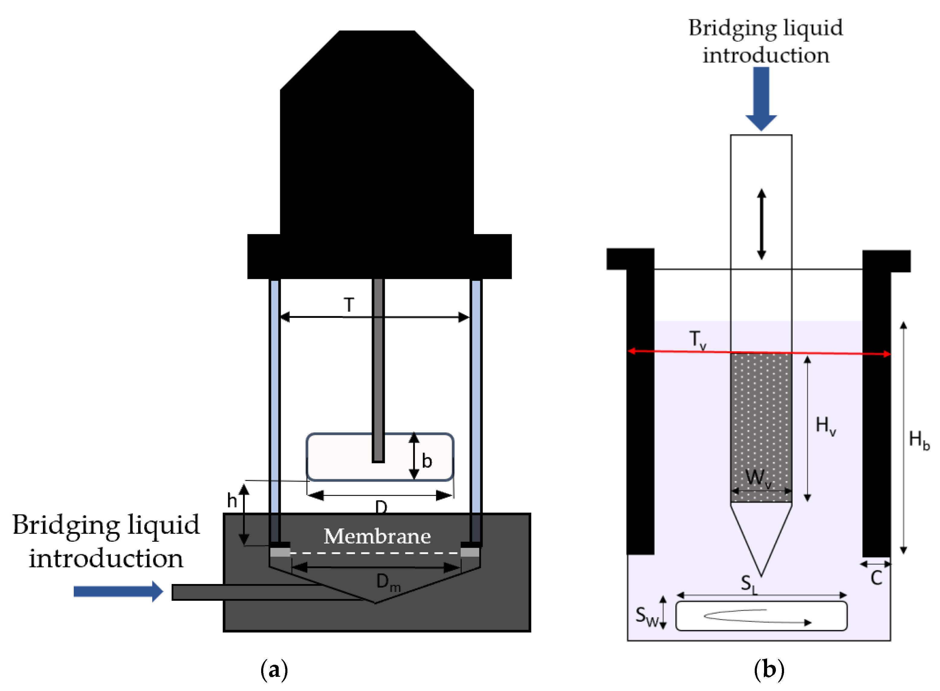
2.1. Dispersion Cell

The dispersion cell consists of a membrane holder, glass chamber and a two-blade impeller which can be fitted on top of the glass chamber. The agitation rate can be adjusted with a voltage knob on a BBH Power 24 V Motor. Two 11 Elite Pumps (Harvard Apparatus, Holliston, MA, USA) were used to feed the solvent and bridging liquid to the crystallization chamber. Benzoic acid dissolved in ethanol was added through the top of the chamber into the water, and the bridging liquid was fed through the bottom of the membrane connected to the chamber with Teflon tubing.
Figure 1 shows the structure of the chamber with its dimensions: membrane diameter, Dm, which is equal to chamber inner width, T, impeller diameter, D, impeller height, b, height from membrane to impeller, h, number of impeller blades, nb and volume below membrane, Vb.

2.2. Oscillating Module

The oscillating module involves a cylindrical membrane attached to a module that moves up and down and is connected to a control panel. The frequency, amplitude distance from peak to peak and voltage can be adjusted on the control panel. Figure 1 shows the different configurations of the dispersion cell (a) and vibrating membrane module (b). For the vibrating module: c is the baffle width, Hb is the baffle height submerged in the bath, Hv is the height of the membrane, Wv is the cylinder membrane diameter, Dp is the pore radius, SL and SW are the stirrer length and width, respectively, Tv is the beaker diameter and n is the number of baffles.

2.3. Membrane

The membranes were supplied by Micropore Technologies Ltd. (Teesside, UK) and were fabricated via the galvanic deposition of nickel into a template formed using the photolithographic technique [17]. The membrane with an annular ring membrane was fabricated using laser interference lithography. The cylindrical membrane for the oscillating module was made from the same material, first as a flat sheet, then rolled and welded on the edge. Both were supplied by Micropore Technologies Ltd. Both types of membranes contained uniform, cylindrical pores with diameters of d p = 18 and hexagonal array spacing of L = 212   μ m . The cylindrical membrane had pores with d p = 17   μ m   and   L = 210   μ m , where the membrane porosity, ε , is given by Equation (1) [17]. The porosity calculated for the flat-disc membrane ( d p = 18   μ m ) was 0.65, and for the cylindrical membrane ( d p = 17   μ m ) , it was 0.59.
ε = π 2 3 ( d p L ) 2  

2.4. Materials

Benzoic acid (C6H5COOH)) (Merck Life Science UK Limited, Gillingham, Dorset, UK) (density ( ρ B A ) = 1316 kg/m3 [22]) was used as a model active pharmaceutical ingredient (API) at a concentration of 30 wt.%, dissolved in ethanol (99.8% purity), and de-ionized water was used as antisolvent. (Lab Grade; Fisher Chemical, Loughborough, UK) was used as bridging liquid at a bridging liquid to crystal solids ratio (BSR, Equation (2)) of 0.7 g/mL.
B S R = V o l u m e   b r i d g i n g   l i q u i d M a s s   o f   c r y s t a l s   ( mL g )  
PTFE tubing was used to connect the inlet to the membrane with the injection syringe (SGE), which injected the bridging liquid through the membrane using a glass-plunger, 25 mL SGE needle syringe mounted on top of an 11 Elite Syringe (Harvard Apparatus, Holliston, MA, USA).

2.5. Procedure

Spherical agglomeration in the membrane system was achieved in three main steps. In both the DC and oscillating membrane module (Figure 2), (step 1) antisolvent crystallization was first performed in the mixing vessel, which was either a beaker or the DC glass chamber, during mixing: the solvent (S: benzoic acid in ethanol) was added to the antisolvent (AS) in a ratio of 1:9 (S:AS) in both systems. Then (step 2), the bridging liquid (toluene) was pumped to reach a BSR of 0.8 mL/g at the corresponding flow rate (Q = V/t). Finally (step 3), the spherical agglomerates were allowed to grow and consolidate as the mixing continued. Shortly after, the spherical agglomerates were removed and separated in Petri dishes for observation (Eclipse TE300, Inverted Microscope, Nikon, Kingston, Surrey, UK), and they were dried for observation after 24 h. For DC, the given flux corresponded to 0.025–0.05 mL/min, and for the oscillating module, it was 0.02–0.05 mL/min. After the antisolvent crystallization step, the crystals formed were mainly needle-shaped and plate-like, ranging in size from 10 to 100 µm. The oscillating module frequency and amplitude were started at the beginning of the experiment and varied from 30 to 70 Hz and 1 to 3, respectively.
The flux, J, through the membrane can be used to compare the results obtained with the DC membrane and the oscillating membrane. The flux is required to be equal in each type of membrane which can be ensured by adjusting the flow rate of bridging liquid through the membrane. The filter area could be found by using the porosity value obtained from Equation (1).
J = F l o w   r a t e   t h r o u g h   m e m b r a n e F i l t e r   s u r f a c e   a r e a     ( L m 2 h )  

3. Results and Discussion

Spherical agglomeration occurs in three main steps (shown in Figure 2) which are aided by membrane technology. The membrane pore radius ensures that there are multiple droplets of the same diameter formed simultaneously, which makes it a scale-up solution to microfluidic or single-capillary systems [11].

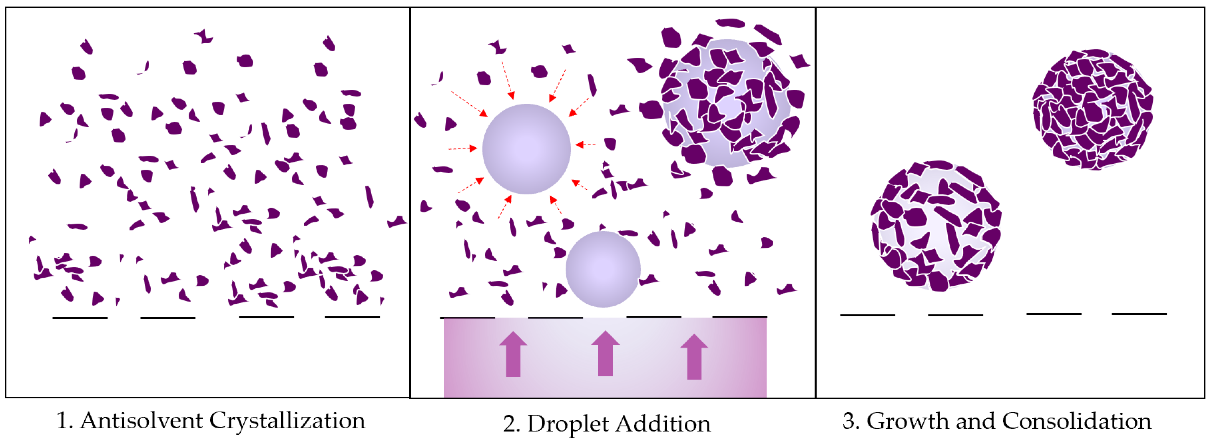
3.1. Agglomerate Formation Mechanism

From off-line observations and previously studied models, it can be inferred that the immersion mechanism in the most dominant in the DC, where the droplets introduced were larger than the crystals, allowing the latter to adsorb onto the surface and consolidate after the addition of toluene is finished. The distribution mechanism might have been more prominent in the oscillating module, where the introduced droplet size was much smaller than the size of the initial crystals, which then adsorbed onto the surface of the crystal, acting like a glue to bring the crystals together into non-smooth spherical agglomerates. The adsorption of the crystals onto the droplet depended on the properties of the interfacial tension of the solvent to antisolvent and the polar affinity of benzoic acid to toluene, which helped it to adsorb onto the toluene droplet.
The balance of the wetting affinity, polarity and respective interfacial tension of the compounds used for spherical agglomeration is important when choosing the right recipe. Each API will require a different recipe, but a similar mechanism of droplet addition can be adopted. A screening process should be performed for other APIs and their appropriate S:AS and bridging liquid systems.

3.2. Optical Microscopy Results

Figure 3 shows the optical microscopy results of benzoic acid spherical agglomerates obtained from (a) the oscillating membrane and (b) the flat membrane in the dispersion cell. Visually, the DC agglomerates appeared smooth and had a clear spherical shape with a greater level of consolidation than the agglomerates from the oscillating module. The poor consolidation with the vibrating module may have been a result of poor mixing conditions due to the magnetic stirrer and the formation of a vortex in the vessel. To aid this, a unit of four baffles was 3D printed using Polypropylene (PP) as material, as it is resistant to corrosive chemicals such as toluene or acetone (used for cleaning). This prevented the formation of a vortex and improved the mixing and formation of monodisperse spherical agglomerates. Since the DC had a built-in two-blade paddle, covered most of the membrane surface and was placed at a distance of 0.5 cm to the membrane, the mixing in the DC was much better and more efficient.
The agglomerates from the oscillating module were more uniformly sized and shaped overall and had a smaller mean size: 212 µm as opposed to the 285 µm mean agglomerate size obtained from the DC. This was a result of a larger surface area of the oscillating membrane available for droplet addition than the surface area of the flat membrane, where droplet detachment was subject to a uniform level of shear. The shear in the DC was mainly generated by the rotation of the impeller, whereas in the oscillating membrane, it was generated by the vibrating movement of the module, and as it shook, it released the droplets from the surface of the membrane. Gravity may also have played a role in the visual results of the agglomerates; as the crystals did not have the same density as the continuous phase (DI water), they preferentially sunk to the bottom of the vessel. In the DC unit, the membrane was at the bottom, so the agglomerates formed preferentially at the bottom during droplet addition. However, the oscillating unit had a vertical membrane set in the middle of the vessel, which corresponded to where the vortex would form at high mixing rates. Because of this, the crystals were mostly found at the bottom and sides of the vessel rather than in the middle, where the droplet introduction occurred. Because of this, there may be less crystals available for agglomerate formation at a time than in the DC, and it would require more time and mixing, as well as more baffles to obtain smooth and spherical agglomerates such as the ones obtained from the DC.
The DC also had a substantial dead-zone area which may have existed in the right-angle corner between the flat membrane and the vertical chamber wall. This could be aided by a curved membrane to mimic a curved bottom of CSRT optimal design, or a membrane that has pores arranged in an annulus ring at the radial distance of the membrane where the highest shear occurs due to agitation.

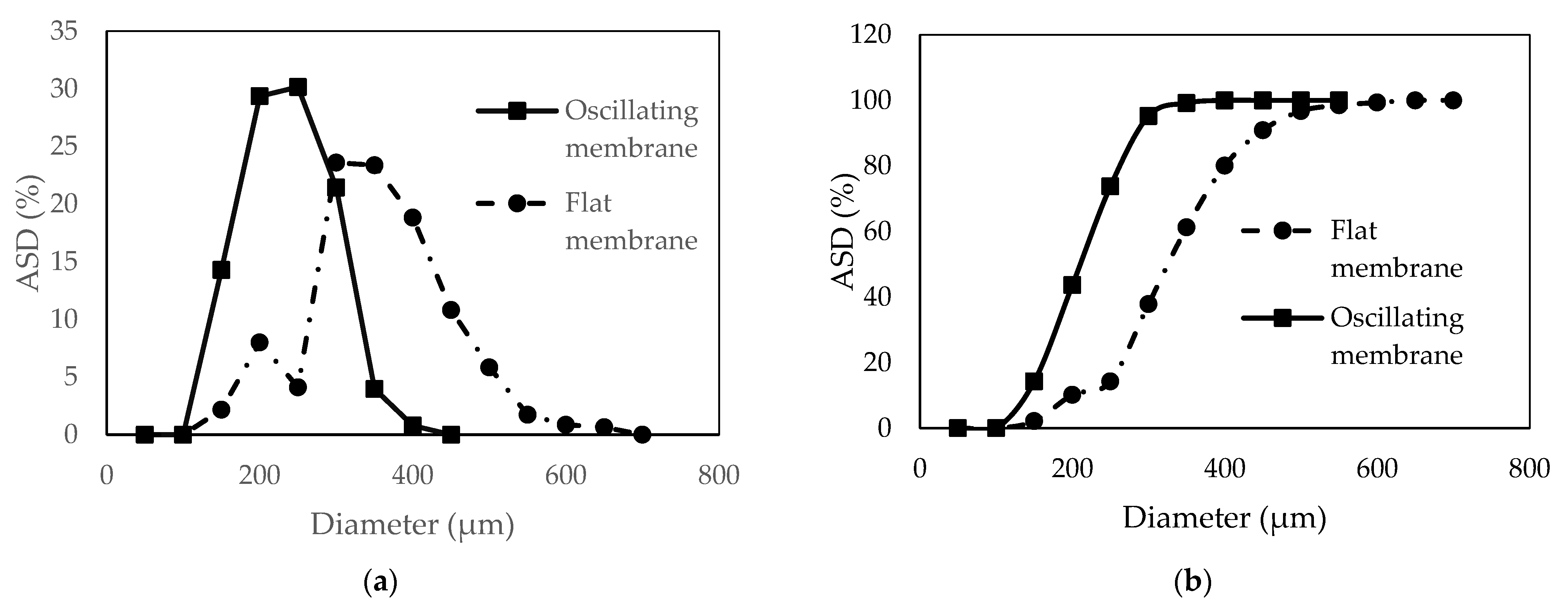
3.3. Agglomerate Size Distribution

The mechanism of shear generation and droplet formation was different in both systems, which affected the final shape and size of the agglomerates. In the flat DC membrane, shear was generated by the agitation of the impeller and was assumed to be constant across the membrane. However, studies show that it is highest about ¾ distance from the center of the membrane in the radial direction [23]. There is a critical point under the blade where the shear was at its highest, the droplets would be smallest and therefore the agglomerates formed there would be smallest. The shear in the vibrating module was generated by the frequency, amplitude and mixing conditions, which caused the droplets to detach from the membrane and fall into the bath of crystals to form agglomerates. Other factors that influenced the droplet size were the interfacial tension, the viscosity and density of the continuous phase (water), the Reynolds number and the dimensions of the tank.
Figure 4 shows the comparison between the agglomerate size distribution (ASD) obtained from the flat membrane and the oscillating module based on number %. The agglomerates obtained from the oscillating membrane had a mean size of around 290 µm compared to 350 µm from the flat membrane. Both modules had similar volumes; therefore, a similar yield of monodisperse agglomerates could be obtained of 70 and 80% for the flat and vibrating membranes, respectively. ASD mean size measurements were conducted in ImageJ, without considering the roughness of the agglomerate crystal surface.
As a surfactant cannot be used to stabilize the toluene droplets, it was not possible to measure the original droplet mean size in situ before they formed agglomerates. The droplets may have been prone to deformation due to impeller or magnetic stirrer mixing. However, since the density of benzoic acid crystals in the suspension is very high, it can be assumed that as soon as the droplets are formed, they meet the crystals. The crystals first adsorb onto the surface of the droplet until full coverage of the droplet surface resulting in hollow-shell agglomerates which were much larger than the initial droplet size, due to droplet expansion after detachment from membrane. Hollow agglomerates formed in the DC in the form of ashell that did not deform after drying, which could have some potential uses if their formation can be predicted. In contrast, the oscillating membrane did not form any fully solid agglomerates such as the ones in the DC. They did not have a smooth spherical shape, and sometimes, they were difficult to distinguish clearly, as sometimes, they formed larger agglomerates.

4. Conclusions

Spherical agglomeration was investigated as a technique that can potentially reduce the number of required stages commonly adopted in pharmaceutical manufacturing such as granulation and wet milling, making it an effective process intensification technique. Two membrane technologies were used to aid the formation of evenly distributed droplets of bridging liquid to help achieve consistent spherical agglomerates. Both membrane systems used in this study, the dispersion cell and the oscillating module, were successful at forming spherical agglomerates; however, the DC offered better mixing conditions. The performance of the oscillating module was enhanced with the use of baffles, but the vessel design and hydrodynamic must be further optimized to ensure better ratio of crystals to membrane surface.
Scale-up opportunities will be considered in near future which includes fed-batch mixed suspension, mixed product removal (MSMPR) continuous crystallizers with inbuilt membranes so that they can perform crystallization and binding liquid addition in the same vessel sequentially. The intended scale-up opportunities will be investigated in presence of in situ process analytical technologies.

Author Contributions

Conceptualization, B.B.; methodology, B.B., M.D. and I.L.; validation, I.L., B.B. and M.D.; formal analysis, I.L., B.B. and M.D.; investigation, I.L.; resources, B.B. and M.D.; data curation, I.L.; writing—original draft preparation, I.L.; writing—review and editing, B.B., I.L. and M.D.; supervision, B.B. and M.D. All authors have read and agreed to the published version of the manuscript.

Funding

This research was funded by the School of AACME, Loughborough University, Loughborough, United Kingdom.

Institutional Review Board Statement

Not applicable.

Informed Consent Statement

Not applicable.

Data Availability Statement

Not applicable.

Conflicts of Interest

The authors declare no conflict of interest.

References

  1. Hatcher, L.; Li, W.; Payne, P.; Benyahia, B.; Rielly, C.D.; Wilson, C.C. Tuning Morphology in Active Pharmaceutical Ingredients: Controlling the Crystal Habit of Lovastatin through Solvent Choice and Non-Size-Matched Polymer Additives. Cryst. Growth Des. 2020, 20, 5854–5862. [Google Scholar] [CrossRef]
  2. Zhou, L.; Su, M.; Benyahia, B.; Singh, A.; Barton, P.I.; Trout, B.L.; Myerson, A.S.; Braatz, R.D. Mathematical modeling and design of layer crystallization in a concentric annulus with and without recirculation. AIChE J. 2013, 59, 1308–1321. [Google Scholar] [CrossRef] [Green Version]
  3. Fysikopoulos, D.; Benyahia, B.; Borsos, A.; Nagy, Z.K.; Rielly, C.D. A Framework for Model Reliability and Estimability Analysis of Crystallization Processes with Multi-Impurity Multi-Dimensional Population Balance Models. Comput. Chem. Eng. 2019, 122, 275–292. [Google Scholar] [CrossRef]
  4. Chen, C.W.; Lee, T. Round Granules of Dimethyl Fumarate by Three-in-One Intensified Process of Reaction, Crystallization, and Spherical Agglomeration in a Common Stirred Tank. Org. Process Res. Dev. 2017, 21, 1326–1339. [Google Scholar] [CrossRef]
  5. Peña, R.; Oliva, J.A.; Burcham, C.L.; Jarmer, D.J.; Nagy, Z.K. Process Intensification through Continuous Spherical Crystallization Using an Oscillatory Flow Baffled Crystallizer. Cryst. Growth Des. 2017, 17, 4776–4784. [Google Scholar] [CrossRef]
  6. Yeap, E.W.Q.; Ng, D.Z.L.; Lai, D.; Ertl, D.J.; Sharpe, S.A.; Khan, S.A. Continuous Flow Droplet-Based Crystallization Platform for Producing Spherical Drug Microparticles. Org. Process Res. Dev. 2019, 23, 93–101. [Google Scholar] [CrossRef]
  7. Peña, R.; Nagy, Z.K. Process Intensification through Continuous Spherical Crystallization Using a Two-Stage Mixed Suspension Mixed Product Removal (MSMPR) System. Cryst. Growth Des. 2015, 15, 4225–4236. [Google Scholar] [CrossRef]
  8. Yeap, E.W.Q.; Acevedo, A.J.; Khan, S.A. Microfluidic Extractive Crystallization for Spherical Drug/Drug-Excipient Microparticle Production. Org. Process Res. Dev. 2019, 23, 375–381. [Google Scholar] [CrossRef]
  9. Thati, J.; Rasmuson, Å.C. Particle engineering of benzoic acid by spherical agglomeration. Eur. J. Pharm. Sci. 2012, 45, 657–667. [Google Scholar] [CrossRef]
  10. Katta, J.; Rasmuson, Å.C. Spherical crystallization of benzoic acid. Int. J. Pharm. 2008, 348, 61–69. [Google Scholar] [CrossRef]
  11. Orlewski, P.M.; Ahn, B.; Mazzotti, M. Tuning the particle sizes in spherical agglomeration. Cryst. Growth Des. 2018, 18, 6257–6265. [Google Scholar] [CrossRef]
  12. Thati, J.; Rasmuson, Å.C. On the mechanisms of formation of spherical agglomerates. Eur. J. Pharm. Sci. 2011, 42, 365–379. [Google Scholar] [CrossRef] [PubMed]
  13. Arjmandi-Tash, O.; Tew, J.D.; Pitt, K.; Smith, R.; Litster, J.D. A new mathematical model for nucleation of spherical agglomerates by the immersion mechanism. Chem. Eng. Sci. X 2019, 4, 100048. [Google Scholar] [CrossRef]
  14. Pitt, K.; Peña, R.; Tew, J.D.; Pal, K.; Smith, R.; Nagy, Z.K.; Litster, J.D. Particle design via spherical agglomeration: A critical review of controlling parameters, rate processes and modelling. Powder Technol. 2018, 326, 327–343. [Google Scholar] [CrossRef]
  15. Lackowska, I.; Dragosavac, M.; Benyahia, B. Spherical Agglomeration of Benzoic Acid Using Membrane Emulsification. In Proceedings of the 4th International Symposium on Pharmaceutical Engineering Research (SPhERe Proceedings 2021), Braunschweig, Germany, 15–17 September 2021. [Google Scholar] [CrossRef]
  16. Chen, K.; Hou, B.; Wu, H.; Huang, X.; Li, F.; Xiao, Y.; Li, J.; Bao, Y.; Hao, H. Hollow and solid spherical azithromycin particles prepared by different spherical crystallization technologies for direct tableting. Processes 2019, 7, 276. [Google Scholar] [CrossRef] [Green Version]
  17. Dragosavac, M.; Sovilj, M.N.; Kosvintsev, S.R.; Holdich, R.G.; Vladisavljević, G.T. Controlled production of oil-in-water emulsions containing unrefined pumpkin seed oil using stirred cell membrane emulsification. J. Memb. Sci. 2008, 322, 178–188. [Google Scholar] [CrossRef] [Green Version]
  18. Zhang, X.; Qin, L.; Su, J.; Sun, Y.; Zhang, L.; Li, J.; Beck-Broichsitter, M.; Muenster, U.; Chen, L.; Mao, S. Engineering large porous microparticles with tailored porosity and sustained drug release behavior for inhalation. Eur. J. Pharm. Biopharm. 2020, 155, 139–146. [Google Scholar] [CrossRef]
  19. Imbrogno, A.; Dragosavac, M.; Piacentini, E.; Vladisavljević, G.; Holdich, R.; Giorno, L. Polycaprolactone multicore-matrix particle for the simultaneous encapsulation of hydrophilic and hydrophobic compounds produced by membrane emulsification and solvent diffusion processes. Colloids Surf. B Biointerfaces 2015, 135, 116–125. [Google Scholar] [CrossRef] [Green Version]
  20. Gehrmann, S.; Bunjes, H. Influence of membrane material on the production of colloidal emulsions by premix membrane emulsification. Eur. J. Pharm. Biopharm. 2018, 126, 140–148. [Google Scholar] [CrossRef]
  21. Joseph, S.; Bunjes, H. Evaluation of Shirasu Porous Glass (SPG) membrane emulsification for the preparation of colloidal lipid drug carrier dispersions. Eur. J. Pharm. Biopharm. 2014, 87, 178–186. [Google Scholar] [CrossRef]
  22. Vladisavljević, G.T.; Wang, B.; Dragosavac, M.M.; Holdich, R.G. Production of food-grade multiple emulsions with high encapsulation yield using oscillating membrane emulsification. Colloids Surf. A Physicochem. Eng. Asp. 2014, 458, 78–84. [Google Scholar] [CrossRef] [Green Version]
  23. Holdich, R.G.; Dragosavac, M.M.; Vladisavljević, G.T.; Kosvintsev, S.R. Membrane Emulsification with Oscillating and Stationary Membranes. Ind. Eng. Chem. Res. 2010, 49, 3810–3817. [Google Scholar] [CrossRef]
Figure 1. Schematic of (a) Dispersion cell with a flat-blade impeller above a flat-disc membrane, with dimensions: Dm = 3.45 cm, T = 3.75 cm, D = 2.95 cm, b = 1.2 cm, h = 0.5 cm, nb = 2, Vb = 4.33 mL; (b) Vibrating membrane module with dimensions: Wv = 1.3 cm, Hv = 6.5 cm, Tv = 4.3 cm, Hb = 3.75 cm, c =0.7 cm, SW = 1.05 cm, SL = 3.8 cm.
Chemproc 09 00002 g001
Figure 2. Spherical agglomeration steps: 1. API dissolved in solvent added to antisolvent to create supersaturation and cause nucleation and growth of crystals. 2. Bridging liquid droplets are introduced through the membrane to allow for crystals to adsorb onto the droplet surface. 3. Droplet addition ends, and spherical agglomerates are still mixed to allow for consolidation and growth of agglomerates.
Chemproc 09 00002 g002
Figure 3. BA SAs at comparable mixing conditions—800RPM, flux = 240 Lm−2h−1, BSR = 0.8, dp = 18 µm, formed in a (top) flat membrane dispersion cell and (bottom) cylindrical membrane in vibrating module.
Chemproc 09 00002 g003
Figure 4. (a) Agglomerate size distribution (ASD) and (b) cumulative size distribution, based on number of spherical agglomerates formed at flux = 240 Lm−2h−1, at 800 RPM, nickel membrane dp = 18 µm.
Chemproc 09 00002 g004
Publisher’s Note: MDPI stays neutral with regard to jurisdictional claims in published maps and institutional affiliations.

