Abstract
Millimeter wave (mmwave) is a potential technology to cater to the data requirements of future cellular networks through its wider spectrum and directional beamforming. With such directional communication, exact alignment of communicating beams is crucial. In this paper, the directivity gains with an antenna model having a Gaussian main lobe is used and the impact of beam alignment error due to random movement of the user are investigated on the uplink system performance of mmwave cellular network. Using stochastic geometry, we have derived Signal-to-Interference-plus-Noise Ratio (SINR) coverage probability. Numerical results show that an optimal number of base station beams exist that maximizes coverage probability at different user velocities and cell radii.
1. Introduction
To meet the capacity requirements of an evolving cellular network, channel measurements have demonstrated the potentials of an mmwave spectrum. The smaller wavelength at mmwave facilitates implementing highly directional steerable antennas with array gains that can mitigate the peculiarities at this band, such as increased path loss, sensitivity to blockages and other-cell interference. In order to achieve the maximum directivity gains, the base station (BS) and user equipment (UE) beams need to be perfectly aligned, but the increased directionality may incur beam misalignment errors [1,2]. This experiment demonstrates that a system operating at a beam misalignment of 18° reduces the link budget by about 17 dB and throughput by up to 6 Gbps or may completely break the connectivity [3].
Considerable research to analyze the performance of mmwave cellular networks exploiting directionality with perfect beam alignment can be found in the literature [4] and references therein, while limited work considers imperfect beam alignment. In practice, if the angle-of-arrival estimation of incoming signal is not accurate, the devices will not be able to steer their main beams accordingly, leading to imperfect beam alignment. Therefore, it is important to incorporate beamsteering errors into the analysis, and practical mmwave systems rely on beam management procedures [5,6]. Several works that demonstrate the effect of beam misalignment on the coverage probability (CP) performance of downlink mmwave cellular networks are presented in [7,8,9]. Other works to determine optimal beamwidth in the presence of beam misalignment that maximizes system throughput and transmission capacity are reported in [10,11]. In addition, mobility-based beam misalignment errors also reduce the received signal strength at UE, which may lie within the side lobe of the previous beam selected during synchronization signal burst (SSB) [6].
In this work, we consider multi-beam transmission and incorporate beam alignment error due to UE mobility in the uplink mathematical model of mmwave cellular systems. Our results show that there exist an optimum number of BS beams that maximize coverage probability at different UE velocities and cell radii. Moreover, an increased number of beams at UE is found to give the best coverage performance due to increased beamforming gain.
2. System Model
We consider a single-tier outdoor mmwave network with BSs and UE distributed in according to Poisson point process (PPP) of density λ and , respectively. Random-sized rectangular buildings are independently distributed according to another PPP. The analysis is conducted for a typical UE that randomly moves in a straight line with velocity m/s. It is assumed that a UE always associates with the BS in LOS with minimum path loss. Universal frequency reuse is assumed across the network with , and each BS has at least one active user to serve at any time. The blockages cause the path length between typical UE and serving BS to be either line-of-sight (LOS) (unblocked path) with probability or non-LOS (blocked path) with probability . Different path loss exponents and path loss intercepts, , are applied to each LOS and NLOS links according to the following functions [12]:
where β is the blockage parameter that depends on the length and width of the building.
The channel fading follows independent Nakagami distribution with the parameters for LOS and NLOS links denoted by and , respectively. The antenna gain is parameterized by the Gaussian main lobe profile [13], and both the BS and UE are capable of random directional beamforming with and beams, respectively, where are integers. The corresponding beamwidths for BS and UE are given as and . The gain of the antenna main lobe and side lobes for BS and UE depends upon the number of beams and is given by following expressions:
where , represents the antenna’s angle relative to its bore-sight direction . The maximum main lobe gain and the side-lobe gain are given by and , respectively. The probability of beam alignment error at BS due to UE mobility is proposed in [6] as . Similarly, the probability of beam misalignment at the UE’s side is given by . The total gain of the desired link (i.e., from typical UE to typical BS) is given by
The interfering UEs have independent and uniformly distributed beam directions over [0, 2]. The total gain on the interfering links is a discrete random variable whose distribution is given by
3. Analysis of SINR Coverage Probability
SINR coverage probability is given by . Given that the link between typical UE and reference BS is LOS, the received SINR at BS at a random distance r is
is desired signal power, is the noise power, denotes the interfering UE, and is the aggregate interference power. The obtained expression for coverage probability is given below,
and are the distribution of the distance () between UE and LOS serving BS [12],
The Laplace transform (LT) of interference can be obtained using the similar steps used in our previous work [14]. The derived expression for LT for is given below:
4. Numerical Results and Discussion
In this section, we solve the derived expressions numerically using MATLAB according to the system parameter listed in Table 1.

Table 1.
Parameters for numerical analysis [6,12].
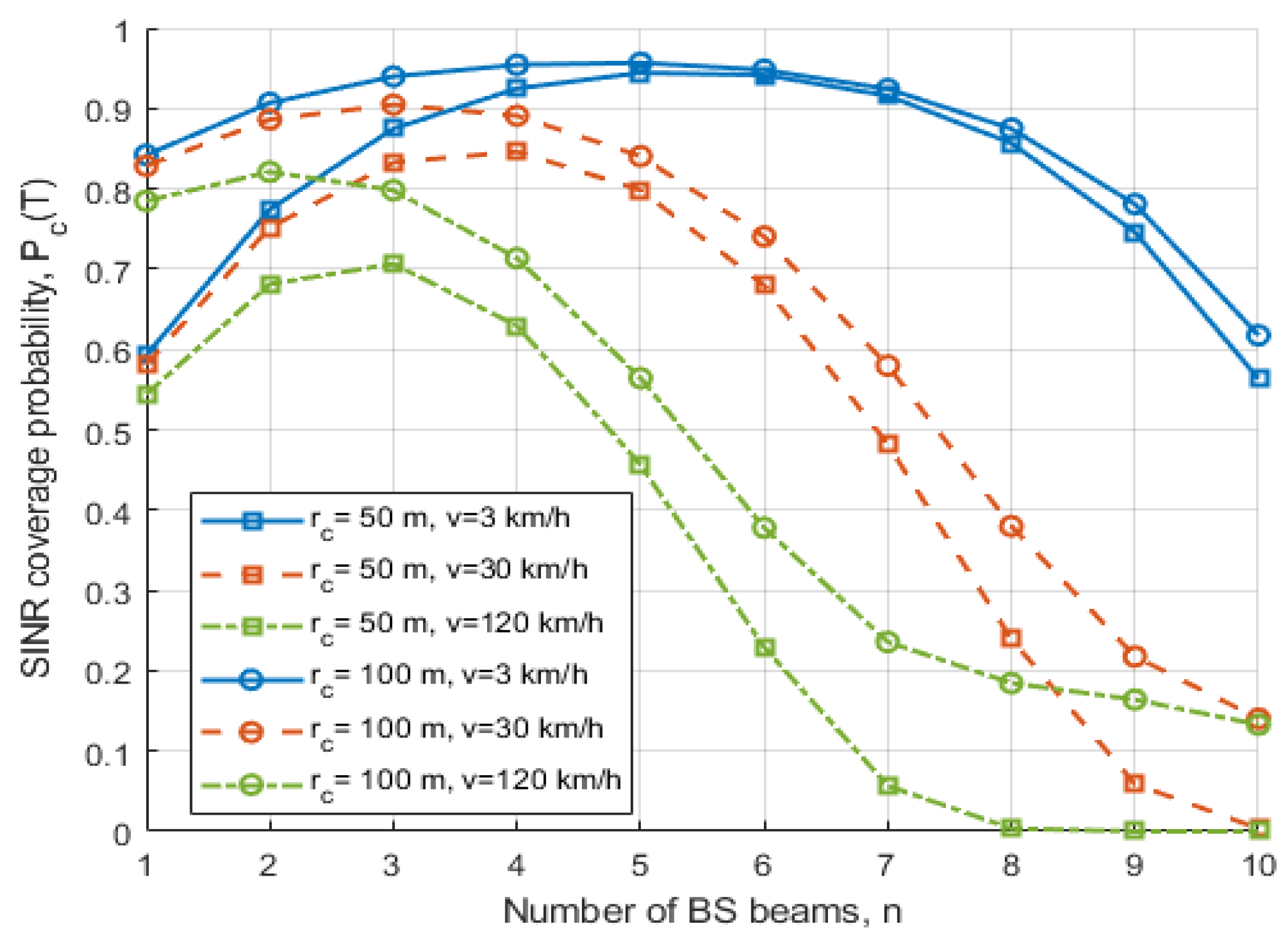
In Figure 1, we analyze the impact of varying cell radii (rc) and for different n. It is observed that for both rc = 50 and 100 m, as n increases, the beamforming gain is increased and the interference at BS is decreased (due to narrow beamwidth). Hence, CP improves initially and reaches a maximum value, giving an optimum number of beams. However, with a further increase in n, the probability of beam misalignment at UE increases, and hence CP decreases. It can be noted that the optimal n required at higher rc is lower compared to that required for lower rc, which represents a dense network with more interference, hence requiring more beams. Additionally, with the increasing , the beam misalignment probability of UE as well as the beam (re)selection and BS handovers are increased. Hence, an increasing decreases the optimum value of n and for a given n, the CP decreases.

Figure 1.
Impact of cell radius and UE velocity on SINR coverage probability for different BS beams.
In Figure 2, we compare the UE with multiple beams k = 2 and 4 with a single beam UE, i.e., k = 1. It can be seen that an increased UE beam at k = 4 provides the best CP due to increased beamforming gains, even though at increased k the probability of beam misalignment at the UE is increased. However, when k = 2, as n increases, a small gain in CP performance is obtained as compared to a single beam due to the overhead associated with the SSB measurement of multiple beams.
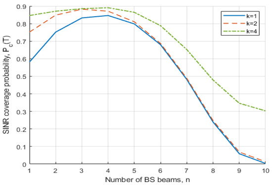
Figure 2.
Impact of UE beams on SINR coverage probability for different BS beams.
5. Conclusions
In this paper, we analyze the impact of multiple beams and beam misalignment error due to UE random movement on the uplink CP of mmwave cellular network. We derive mathematical expressions for SINR CP to determine the effect of BS and UE beams, probability of beam misalignment, UE velocity and cell radius. The results demonstrate that an optimum BS beam exists that maximizes CP at different UE velocities and cell radii. Moreover, increasing the number of beams at UE is found to have the best coverage performance due to increased beamforming gain.
Author Contributions
H.M. formulated the system design, developed the theoretical model, performed numerical analysis and wrote the manuscript. I.A. and M.I.A. verified the analytical methods and findings, provided useful feedback and reviewed the manuscript. All authors have read and agreed to the published version of the manuscript.
Funding
This research received no external funding.
Data Availability Statement
Not applicable.
Conflicts of Interest
The authors declare no conflict of interest.
References
- Rappaport, T.S.; Xing, Y.; MacCartney, G.R.; Molisch, A.F.; Mellios, E.; Zhang, J. Overview of Millimeter Wave Communications for Fifth-Generation (5G) Wireless Networks—With a Focus on Propagation Models. IEEE Trans. Antennas Propag. 2017, 65, 6213–6230. [Google Scholar] [CrossRef]
- MacCartney, G.R.; Samimi, M.K.; Rappaport, T.S. Exploiting directionality for millimeter-wave wireless system improvement. In Proceedings of the 2015 IEEE International Conference on Communications (ICC), London, UK, 8–12 June 2015; pp. 2416–2422. [Google Scholar]
- Nitsche, T.; Flores, A.B.; Knightly, E.W.; Widmer, J. Steering with Eyes Closed: Mm-Wave Beam Steering without In-Band Measurement. In Proceedings of the 2015 IEEE Conference on Computer Communications (INFOCOM), Hong Kong, China, 26 April 2015–1 May 2015. [Google Scholar]
- Andrews, J.G.; Bai, T.; Kulkarni, M.N.; Alkhateeb, A.; Gupta, A.K.; Heath, R.W. Modeling and analyzing millimeter wave cellular systems. IEEE Trans. Commun. 2016, 65, 403–430. [Google Scholar] [CrossRef] [Green Version]
- Singh, S.; Kulkarni, M.N.; Ghosh, A.; Andrews, J.G. Tractable model for rate in self-backhauled millimeter wave cellular networks. IEEE J. Sel. Areas Commun. 2015, 33, 2196–2211. [Google Scholar] [CrossRef] [Green Version]
- Kalamkar, S.S.; Baccelli, F.; Abinader, F.M.; Marcano Fani, A.S.; Uzeda Garcia, L.G. Beam Management in 5G: A Stochastic Geometry Analysis. IEEE Trans. Wirel. Commun. 2021, 21, 2275–2290. [Google Scholar] [CrossRef]
- Di Renzo, M. Stochastic geometry modeling and analysis of multi-tier millimeter wave cellular networks. IEEE Trans. Wirel. Commun. 2015, 14, 5038–5057. [Google Scholar] [CrossRef] [Green Version]
- Turgut, E.; Gursoy, M.C. Coverage in heterogeneous downlink millimeter wave cellular networks. IEEE Trans. Commun. 2017, 65, 4463–4477. [Google Scholar] [CrossRef]
- Cheng, M.; Wang, J.-B.; Wu, Y.; Xia, X.-G.; Wong, K.-K.; Lin, M. Coverage analysis for millimeter wave cellular networks with imperfect beam alignment. IEEE Trans. Veh. Technol. 2018, 67, 8302–8314. [Google Scholar] [CrossRef] [Green Version]
- Yang, G.; Member, S.; Du, J.; Xiao, M.; Member, S. Analysis on 60 GHz Wireless Communications with Beamwidth-Dependent Misalignment. arXiv 2016, arXiv:1611.07867. [Google Scholar]
- Wildman, J.; Nardelli, P.H.J.; Latva-aho, M.; Weber, S. On the joint impact of beamwidth and orientation error on throughput in directional wireless poisson networks. IEEE Trans. Wirel. Commun. 2014, 13, 7072–7085. [Google Scholar] [CrossRef]
- Bai, T.; Heath, R.W. Coverage and Rate Analysis for Millimeter-Wave Cellular Networks. IEEE Trans. Wirel. Commun. 2015, 14, 1100–1114. [Google Scholar] [CrossRef]
- Yang, G.; Xiao, M. Performance Analysis of Millimeter-Wave Relaying: Impacts of Beamwidth and Self-Interference. IEEE Trans. Commun. 2018, 66, 589–600. [Google Scholar] [CrossRef] [Green Version]
- Mariam, H.; Ahmed, I.; Aslam, M.I. Coverage probability of uplink millimeter wave cellular network with non-homogeneous interferers’ point process. Phys. Commun. 2021, 45, 101274. [Google Scholar] [CrossRef]

Publisher’s Note: MDPI stays neutral with regard to jurisdictional claims in published maps and institutional affiliations. |
© 2022 by the authors. Licensee MDPI, Basel, Switzerland. This article is an open access article distributed under the terms and conditions of the Creative Commons Attribution (CC BY) license (https://creativecommons.org/licenses/by/4.0/).