1. Introduction
As an important part of forging machinery, hydraulic presses are widely used in aerospace, automobiles, shipbuilding, and other fields. The mobile station is one of the important components of the whole equipment, and its main role is the installation, fixation, and movement of the workpiece. With the use of hydraulic presses in the manufacturing industry, the impact wear caused by the working force on the support structure of hydraulic press stations has become the focus of increasing attention. Therefore, it is of great significance to carry out structural innovation design for the mobile station system of the hydraulic press to improve the mechanical performance of the hydraulic press structure.
TRIZ theory, as a complete method to solve the problem innovatively, has been a vital inspiration for designers to carry out innovative design [
1,
2]. At present, scholars have carried out a series of studies on the structural design of hydraulic machine mobile stations and TRIZ theory:
(1) In the structural design of hydraulic press, Dong et al. [
3] optimized the structure of the sliding table on the basis of the traditional double-station sliding table structure and ensured the rapid conversion in the actual production process. Du et al. [
4] optimized the positioning of the mobile workbench, sliding surface tension, and installation and fixing of touch tools;
(2) The application of TRIZ theory in product innovation design. Zhao. D. et al. [
5] used TRIZ theory to optimize the problems existing in the helmet and improved the safety of the helmet. Wang et al. [
6] used the method of combining extension analysis with TRIZ theory to solve the problems of low efficiency and bulky products of the existing camp trolley folding mode. Li et al. [
7] used the Su-Field Model and the contradiction resolution principle in TRIZ theory to carry out an innovative design of the solar cutting machine. Yang et al. [
8] optimized the luggage box design process by the TRIZ invention principle, optimizing the user’s use and improving the user experience;
(3) The application of TRIZ theory in process innovation design. Wang. C. N et al. [
9] used TRIZ theory to carry out an innovative design of an integrated stern tube, which improved shipbuilding capacity and reduced noise. Liu et al. [
10] proposed an adaptive clamping solution for large aircraft structural parts by using the TRIZ innovation theory analysis tool, which effectively avoided the deformation of parts and improved the clamping efficiency. Almeida et al. [
11] applied the TRIZ method to propose a design for a new WEDM machine tool combined with six-axis robot machining.
Based on the above literature, it can be seen that during the structural design of the hydraulic press workbench, the roller guide rail is still a force component, and there is a possibility of force deformation after long-term work. In view of the TRIZ theory being applied to the research of machine tool innovation design, the theory is mostly used for the clamping force of the workbench, and the overall stress requirement of the workbench is not high. Therefore, based on TRIZ theory, this paper carries out an innovative design of a hydraulic machine mobile workbench system. First, using analysis tools to analyze the problem of a mobile workbench, we can clearly see the essence of the problem. Secondly, the problem-solving tool is used to solve the problem and obtain the problem-solving scheme. Finally, the final scheme is obtained by evaluating the scheme against actual needs.
2. Problem Analysis Based on TRIZ Theory
To some extent, analyzing problems is often more important than solving them. TRIZ theory contains a variety of tools for analyzing and solving practical problems. As one of the effective tools to solve practical engineering problems, TRIZ theory has been widely used in innovative design, optimization, and improvement.
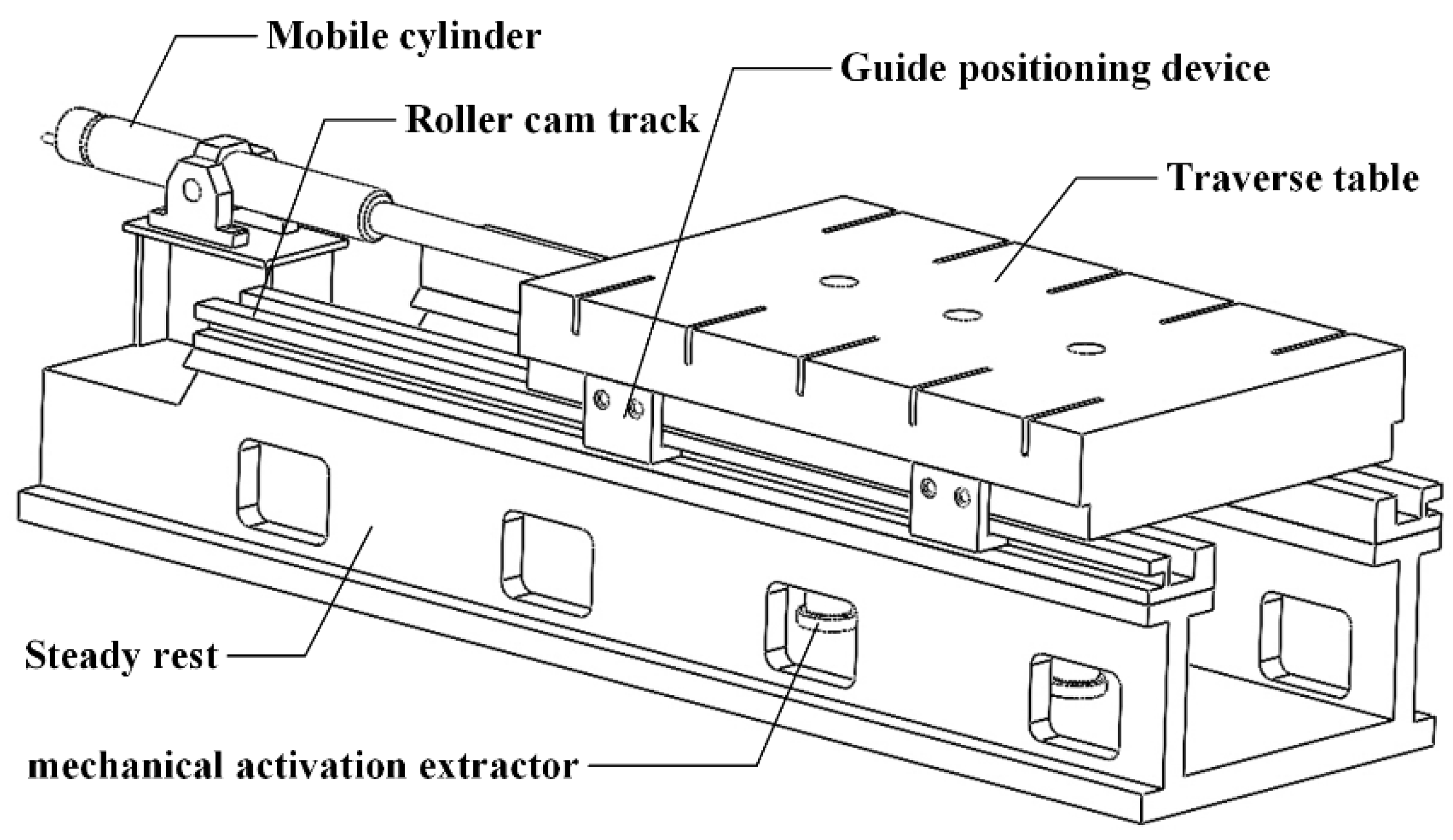
As shown in
Figure 1, which is the structural diagram of the hydraulic machine moving table. According to the literature, the current design of hydraulic machine mobile workbench is primarily based on the three stages listed below:
Stage 1: Workbench moving stage. The process mainly depends on the rolling of the roller on the guide rail to realize the movement of the workbench. In this process, in order to avoid the worktable jumping, a special guide positioning device is designed for auxiliary movement;
Stage 2: Workpiece processing stage. In the traditional design, the roller directly contacts the guide rail, and its contact area is small, so the damage to the roller and the guide rail is large. At present, the designers use the telescopic roller bracket to optimize the traditional structure. After the workbench moves to the processing area, the roller is first retracted, so that the height of the station is reduced to the contact between the lower surface of the workbench and the guide rail;
Stage 3: Pick-up stage. At this stage, the designer designed a special clamping device. After the workpiece is processed, the clamping device is first used to limit the displacement of the station, and then the workpiece is removed from the station by the ejector.
According to the existing structure scheme, a special structure is designed to assist the worktable in stages 1 and 3. Although the scheme meets the target requirements, it also improves the complexity of the structure. In stage 2, the force condition of the station was improved by increasing the contact area, but the guide rail was still affected by the working force. Although the emergence of the problem will not affect the normal processing of the workpiece, there is also an unreasonable structural stress made.
Therefore, for the purpose of technical transformation and improvement, relying on the existing main structure and taking the hydraulic press mobile workbench as the key design object, innovative design requirements are put forward: on the basis of meeting the normal processing of the workpiece, the structural complexity of the mobile workbench system should be reduced, and the deformation of the guide rail after bearing the working force should be avoided.
As shown in
Figure 2, the system component analysis model is established. The system diagram shows all the functional relationships among the functional components and describes the functional relationships among the components through standard, insufficient, excessive, and harmful effects to determine the functional factors leading to the problems.
3. Stage Scheme Design Based on TRIZ Theory
TRIZ theory has a clear definition and a complete and operable principle for innovative design. Its solutions to practical problems are mainly based on the TRIZ problem model. Through analysis, contradictions in the system are obtained, and two contradictory forms of physical contradiction and technical contradiction are proposed. In view of the two different forms, the original understanding obtained by solving strategies such as contradiction matrix and separation principle is used to solve the contradiction innovatively, in order to stimulate designers’ design inspiration to obtain innovative solutions.
3.1. Stage of Workbench Moving
In the design process, it is necessary to limit the freedom of the roller in both the Y and Z directions in order to avoid the lateral movement and jump of the workbench during the movement, which is bound to introduce the corresponding devices or facilities, but this increases the complexity of the system. Combined with computer-aided technology, according to TRIZ problem description requirements, the station movement problem is transformed into a problem model. The designer formalizes the problem according to the format of the problem description template SVOP as: expected ‘roller + reduction + degree of freedom + moderate’; avoid ‘guide device + improvement + complexity + explicit’, as shown in
Figure 3.
After the description of technical problems is completed, the system matches the description content with the general engineering parameters in the classical conflict matrix and then gives the corresponding innovative solution principle, as shown in
Figure 4. The contradiction parameters obtained by the problem description system are: improving the ‘shape’ and deteriorating the ‘complexity of the system’. Then, corresponding to the classical process conflict matrix, the invention principle is: invention principle 16 (insufficient or excessive action), invention principle 29 (pressure and hydraulic structure), 1 (segmentation), and invention principle 28 (mechanical system replacement). After analyzing the original understanding, the designers obtain the corresponding inspiration.
According to the invention principle 29 (air pressure and hydraulic structure), the roller bracket adopts an air pressure structure while deepening the depth of the roller groove on the guide rail. In the process of roller movement, the guide rail structure is used to restrict the freedom of the Y direction, and the pressure structure makes the roller subject to downward pressure, so the freedom of the Z direction is limited.
3.2. Stage of Workpiece Processing
According to the current design scheme, the force deformation of the guide rail structure still exists. Therefore, the force capacity of the guide rail and the change of its structure constitute a pair of process conflicts, which need to be solved innovatively.
According to TRIZ problem description requirements, the problem is formally described as follows: expected ‘guide rail + bear + work force + improve’; avoid ‘guide rail + change + structure + show’. Then the description is matched with the conflict matrix table to obtain the conflict parameter pair, where the reinforcement parameter is ‘pressure’ and the weakening parameter is ‘shape’. The corresponding invention principles are: invention principle 35 (physical or chemical state changes), invention principle 4 (asymmetric), invention principle 15 (dynamic characteristics), and invention principle 10 (pre-action).
The analysis shows that the invention principles: 15 (dynamic characteristics) and the invention principle 10 (pre-effect) have great inspiration to solve the problem. The inspiration is to use the ‘dynamic characteristics’, considering the moving area on the guide rail and the processing area, so that each part can change the relative position. At this point, only the processing area in the guide rail is likely to deform. Then use the ‘advance effect’ to enhance the strength of the rail processing area so that it can withstand more powerful effects.
A new problem appears after the guide rail is segmented: the guide rail in the processing area needs to increase its strength, but at the same time, the reinforced guide rail is still directly affected by the working force, so this problem has not been completely solved. Establish a field model as shown in
Figure 5a. Using the standard solution, since this problem belongs to the harmful effect model, a complex field model is constructed by considering the guide rail structure at the machining position, as shown in
Figure 5b. Since the guide rail needs to bear a strong role, the guide rail below the roller in the processing area is replaced by the hydraulic cylinder structure. In addition, in order to facilitate the movement of the roller, inspired by the movement scheme one, the upper end face of the piston rod can be machined into a channel to facilitate the movement of the roller.
At this time, although the hydraulic support structure can meet the requirements of force, the structure still relies on the roller support workbench when the roller moves to the target position, and the roller still has the possibility of deformation. Therefore, the object-field model is established as shown in
Figure 6a. The system elements of the object-field model are complete, but the hydraulic cylinder S3 has a harmful effect on the pressure field F3 generated by the roller S2. Therefore, designers consider reducing the height of the workbench to make the lower surface of the workbench contact with the upper surface of the piston of the hydraulic cylinder, so the pressure of the hydraulic press is completely borne by the hydraulic cylinder in the working process. Therefore, the auxiliary telescopic device S4 and the physical field model F4 are added, as shown in
Figure 6b. The specific scheme is that the roller bracket is changed to the pneumatic telescopic device. When the workbench moves to the processing area, the roller bracket is converted to a floating state, and the workbench moves downward to the lower surface in contact with the piston. After processing, the roller is extended to make the workbench move upward. However, the degrees of freedom in the X and Z directions of the workbench are limited. However, as the machining vibration occurs, the workbench will shake in the Y direction.
After analyzing the invention principle that meets the contradictory needs with professional knowledge, designers believe that invention principle 28 (replaced by the mechanical system) has great inspiration for the solution to the physical contradiction. That is, when the workbench reaches the processing area, the hydraulic cylinder piston rod moves upward, and the piston rod will move downward after processing to restore the original position of the roller. Therefore, the linkage mechanism is shown in
Figure 7.
3.3. Stage of Workpiece Removal
When combined with the support scheme, when the workpiece is processed, the system relies on the ejector to loosen the workpiece, although the mobile workbench has the risk of lifting. However, according to the clamping structure shown in
Figure 7, when the workpiece is taken, the clamping structure presses the workbench and fixes the workbench in the vertical direction.
4. Innovative Scheme Evaluation
In the above design, the scheme focuses on innovative design from the perspective of roller bracket structure. From the perspective of TRIZ theory, the scheme is to remove harmful functions so that the harmful functions (guideway deformation caused by working force) and structural complexity (design of special structure auxiliary processing) will be the lowest. By using this structure, the roller is no longer affected by the working force in the machining process which effectively avoids the deformation and even damage of the roller. On the other hand, when the workpiece is processed, the scheme adopts the form of a hydraulic cylinder to support the workbench. At the same time, a linkage mechanism is designed to realize the clamping and relaxation of the workbench by the upper and lower movements of the piston rod of the hydraulic cylinder, which improves the stability of the equipment.
Therefore, the design results not only meet the mobile needs of the workbench but also use the hydraulic cylinder as the support structure to facilitate the installation and save space. The structure can completely avoid the bearing force of the guide rail and the roller. Finally, the structural complexity of the whole system is also reduced by fixing the workbench through the linkage mechanism in the process of fetching. Its structure is shown in
Figure 8.
5. Conclusions
In this paper, the innovative design of the hydraulic machine mobile workbench system is taken as the research object. In view of the problems of impact wear and stress deformation of the support structure in the existing design, the system function model is established to sort out the negative function of the hydraulic machine mobile workbench system, clarify the essence of the problem, and find its technical contradiction. The corresponding invention principle is obtained by the conflict matrix to inspire designers to carry out preliminary scheme design. The field model is established to analyze the unresolved conflicts in the preliminary design scheme, and the standard solution is used to solve the conflicts again to obtain the final design scheme. In the new scheme, the hydraulic cylinder structure can effectively reduce the structural complexity of the workbench system, improve the stress condition of the guide rail, and avoid damage to the guide rail and the roller. It provides a new and innovative design idea for designers.


