Proceeding Paper

An In-Depth Analytical Study of Switching States of Direct Torque Control Algorithm for Induction Motor over the Entire Speed Range †

1
Mechatronics & Laboratory Engineering Department, Sham University, Aleppo 11566, Syria
2
Wolfson Centre for Magnetics, School of Engineering, Cardiff University, Cardiff CF24 3AA, UK
3
Instrumentation & Electrical Division, Gas Transmission and Supply Department, Sirte Oil Company for Production, Manufacturing of Oil and Gas, Marsa Al Brega 385, Libya
*
Author to whom correspondence should be addressed.
Presented at the 1st International Electronic Conference on Machines and Applications, 15–30 September 2022; Available online: https://iecma2021.sciforum.net.
Eng. Proc. 2022, 24(1), 27; https://doi.org/10.3390/IECMA2022-12900
Published: 15 September 2022

Abstract

:
In this paper, a full analysis of voltage vectors (VVs) in the DTC algorithm is presented. The analytical analysis shows that the application of specific VVs results in false switching states called uncontrollable angles (UCAs). A robust scheme that ensures the elimination of UCAs is proposed for medium and high speeds with (18) subsectors (SSs). Simulation results are obtained and validated using MATLAB/Simulink.

1. Introduction

Direct torque control (DTC) is characterized by a fast dynamic response and structural simplicity, and is much simpler than the FOC [1,2,3]. Several improvements have been made to overcome problems associated with the DTC drive, particularly high torque ripple [4]. Reference [5] provided an in-depth study of the VV effect on the state variables issue over the entire speed range in terms of UnAs. To select the appropriate VV, a new approach is initially introduced by inserting the zero VV along with the selected one [6]. Research [7] eliminated zero VVs during torque dynamics to establish a fast torque response in the transient state. A modified LUT for the DTC of the three-level dual VSI fed open-ended winding IM drive was proposed in [8], where the VV selection for lower hysteresis boundary conditions was restructured with null voltages. Authors in [9] used the concept of virtual vectors for a seven-phase IM where the torque ripple in different operation conditions was investigated. Different ratios of dc-link voltage were used to drive a universal LUT that was proposed for OW-PMSM. [10,11,12]. The proposed strategy effectively optimized the duty ratio of fundamental VV to minimize the error between the reference VV and the final VV imposed on motor terminals. A duty ratio regulator that considers the operating speed impact on the torque deviation of the active voltage vectors was proposed in [11]. This article suggests an enhanced, simple, and effective DTFRC strategy that aims to eliminate the UnAs over the wide speed range. The proposed method, which uses (18) SSs for the rotor at medium and high speeds, overcomes the conventional DTRFC with (six) sectors in terms of the UnAs. Simulations and experimental results are presented to show and compare the effectiveness of the proposed (18) SS scheme in the DTRFC algorithm of IM.

2. Theoretical Background

2.1. Analytical Modeling

The basic principle of DTRFC is summed up in the instantaneous control of both rotor flux and the torque using intermediate loops without current controls, and the two components of the rotor flux vector of the rotor are estimated in the stator reference frame (αss), as in (1) and (2) [13].
Φ r α s = L r L m ( Φ s α s σ L s i s α s )
Φ r α ( β ) s = L r L m ( Φ s α ( β ) s σ L s i s α ( β ) s )
where Lm is the mutual inductance. Ls and Lr are the stator and rotor self-inductance, respectively. σ is the leakage factor.
The rotor flux vector will be oriented according to α-coordinate axis. Thus, the imaginary component of the rotor flux vector will be zero, i.e.,: Φ r β = 0 ,   Φ r = Φ r α . The derivatives of two controlled variables (Φr, Tem) are known in (3), (4) and (5) [5].
S Φ r = k Φ r ( Φ r _ ref Φ r ) [ L m σ L s τ r Re ( Φ _ s ) ( 1 σ τ r ) Φ r ]
dS Φ r dt = d Φ r dt ( k Φ r 1 σ τ r ) L m σ L s τ r [ Re ( V _ s R s i _ s j ω s Φ _ s ) ]
dS T em dt = dT em _ est dt = ( 1 σ τ s + 1 σ τ r ) T em pL m σ L s L r Im [ V _ s Φ _ r * j ω Φ _ s Φ _ r * ]
where k Φ r is an optional positive constant. Depending on the previous equations, the block diagram of the DTRFC algorithm can be constructed.
To enhance the performance at medium and high speeds, a transition will be facilitated between the conventional strategy with (6) sectors for the low-speed range, and the improved strategy with (18) SSs (for medium and high speeds), as shown in Figure 1.

2.2. Determination of the UnAs Values for Low and High Speeds

Depending on Equations (2) and (3), the effect of applying Vi+1 and Vi−1 on dSΦr at low speeds (20% ωn) and Vi+2 and Vi−2 at high speeds is analyzed. There are two UCAs at low speeds and high speeds, each with a value of π/69 rad/s and π/94 rad/s, respectively. In addition, an analytical study for the two VVs is performed, i.e, (Vi+1 and Vi+2), on dSTem at high speeds. There are two UCAs, each of them with a value equal to π/13 rad/s (22%) of the sector. Table 1 summarizes the values of the UnAs for each (dSΦr and dSTem) over the entire speed range.

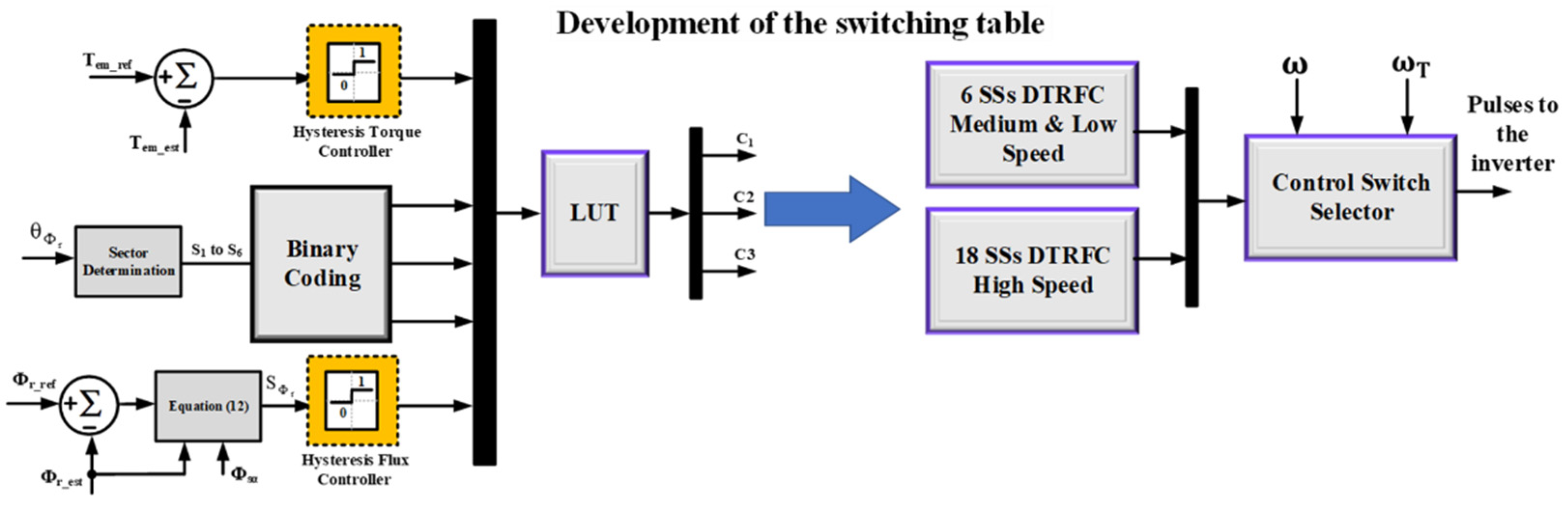
2.3. The Improved Strategy (18) SS DTRFC Strategy for Medium–High Speeds

The proposed strategy is based on dividing the path of the rotor flux into (18) unequal SSs. Every three subsequent sectors will repeat the same distance after the previous three SSs. Depending on Equations (2) and (3), the position of the error change for the rotor flux and torque for a high speed (75% ωn) is analyzed in order to devise the improved lookup table. The LUT for the improved strategy is shown in Table 2.
For the rest of the SSs, the applied vectors can be known by increasing the vector index by (1) when moving between SSs, according to the following sequence:
  • The first, fourth, seventh, tenth, thirteenth, and sixteenth SSs;
  • The second, fifth, eighth, eleventh, fourteenth, and seventeenth SSs;
  • The third, sixth, ninth, twelfth, fifteenth, and eighteenth SSs.

2.4. Determination of the Transition Speed ωT between the Traditional and the Proposed Strategy

It is important to determine the speed at which UnAs start to appear, i.e., the transition speed ωT. An increment is given to the angle θΦr so it scans the entire sector. The speed is given a value starting from zero within an iterative loop during which the two components (V, V) are calculated. The derivatives (dSΦr and dSTem) are calculated according to the two equations (2&3). The speed range at which UnAs disappears are within (0:55% ωn) or (0:155 rad/s). However, if the speed exceeds (155/rad/s), UnAs start to appear.

3. Simulation Results and Discussion

By simulating the proposed block diagram, in the MATALB/Simulink environment, for the motor with the parameters in the Appendix A (Table A1). The simulation results are obtained in Figure 2. The speed of 180 rad/s which equals (63% ωn) is chosen as a transition value between the conventional strategy and the improved one (18 SSs). The transition to the improved strategy is allowed with a chosen high speed 195rad/s. at 3s. A good regulation process around the reference values Φr-ref = 0.945 Wb, Tem-ref = 1.76 N.m can be achieved. The transition speed ωT = 155 rad/s is the minimum value that ensures an absence of UnAs due to the correct selection of VVs, according to the improved LUT in Table 2.

4. Conclusions

This paper provides an analytical investigation of the DTRFC algorithm over the en-tire speed range in terms of UnAs. The proposed scheme with (18) SSs is devised to eliminate the UnAs of some VVs for medium and high speeds, yielding a correct torque response. The transition speed value, at which the UnAs begin to appear, is precisely analytically determined. Furthermore, the proposed method combines the advantages of conventional and improved strategies to work over a wide speed range. The simulation results validate the feasibility and effectiveness of the proposed scheme in IM drives over the wide speed range.
Artificial network techniques for the transition state between the two algorithms represent the main goal for future work.

Author Contributions

Conceptualization, M.M.A. and M.E.; methodology, M.M.A.; software, M.M.A.; validation, M.M.A., M.E. and F.A.; formal analysis, M.M.A.; investigation, M.M.A.; resources, M.E.; data curation, M.M.A., M.E. and F.A.; writing—original draft preparation, M.M.A.; writing—review and editing, M.M.A., M.E. and F.A.; visualization, M.M.A.; supervision, M.E. and F.A.; project administration, M.M.A.; funding acquisition, M.M.A. and M.E. All authors have read and agreed to the published version of the manuscript.

Funding

This research received no external funding.

Institutional Review Board Statement

Not applicable.

Informed Consent Statement

Not applicable.

Data Availability Statement

Not applicable.

Conflicts of Interest

The authors declare no conflict of interest.

Appendix A

Table A1. Parameters of three-phase induction motor.
IM ParametersValues
Nominal voltage230/400 V
Phase resistance statorRs = 45.83 Ω
Phase resistance rotorRr = 31 Ω
Phase inductance statorLs = 1.24 H
Phase inductance rotorLr = 1.11 H
Mutual inductanceLm = 1.05 H
InertiaJ = 0.006 kg.m2
Friction factorf = 0.001 N.m.s/rad
Number of pole pairsp = 2
Nominal stator fluxΦs = 1.14 Wb
Nominal rotor fluxΦr = 0.945 Wb
Nominal powerPn = 0.25 kW
Nominal frequencyF = 50 Hz
Nominal speedωn = 282 rad/s
Nominal torqueTem = 1.76 N.m

References

  1. Takahashi, I.; Noguchi, T. A New Quick-Response and High-Efficiency Control Strategy of an Induction Motor. IEEE Trans. Ind. Appl. 1986, IA-22, 820–827. [Google Scholar] [CrossRef]
  2. Buja, G.; Kazmierkowski, M. Direct Torque Control of PWM Inverter-Fed AC Motors—A Survey. IEEE Trans. Ind. Electron. 2004, 51, 744–757. [Google Scholar] [CrossRef]
  3. Idris, N.; Yatim, A. Direct Torque Control of Induction Machines With Constant Switching Frequency and Reduced Torque Ripple. IEEE Trans. Ind. Electron. 2004, 51, 758–767. [Google Scholar] [CrossRef]
  4. Toh, C.; Idris, N.; Yatim, A. Constant and High Switching Frequency Torque Controller for DTC Drives. IEEE Power Electron. Lett. 2005, 3, 76–80. [Google Scholar] [CrossRef]
  5. Naassani, A.; Monmasson, E.; Louis, J.-P. Synthesis of Direct Torque and Rotor Flux Control Algorithms by Means of Sliding-Mode Theory. IEEE Trans. Ind. Electron. 2005, 52, 785–799. [Google Scholar] [CrossRef]
  6. Nikzad, M.R.; Asaei, B.; Ahmadi, S.O. Discrete Duty-Cycle-Control Method for Direct Torque Control of Induction Motor Drives With Model Predictive Solution. IEEE Trans. Power Electron. 2017, 33, 2317–2329. [Google Scholar] [CrossRef]
  7. Alsofyani, I.M.; Bak, Y.; Lee, K.-B. Fast Torque Control and Minimized Sector-Flux Droop for Constant Frequency Torque Controller Based DTC of Induction Machines. IEEE Trans. Power Electron. 2019, 34, 12141–12153. [Google Scholar] [CrossRef]
  8. Meesala, R.E.K.; Thippiripati, V.K. An Improved Direct Torque Control of Three-Level Dual Inverter Fed Open-Ended Winding Induction Motor Drive Based on Modified Look-Up Table. IEEE Trans. Power Electron. 2019, 35, 3906–3917. [Google Scholar] [CrossRef]
  9. Yang, G.; Yang, J.; Li, S.; Wang, Y.; Hussain, H.; Deng, R.; Yan, L. A Sequential Direct Torque Control Scheme for Seven-Phase Induction Machines Based on Virtual Voltage Vectors. IEEE Trans. Ind. Appl. 2021, 57, 3722–3734. [Google Scholar] [CrossRef]
  10. Wang, M.; Sun, D.; Ke, W.; Nian, H. A Universal Lookup Table-Based Direct Torque Control for OW-PMSM Drives. IEEE Trans. Power Electron. 2020, 36, 6188–6191. [Google Scholar] [CrossRef]
  11. Wu, X.; Huang, W.; Lin, X.; Jiang, W.; Zhao, Y.; Zhu, S. Direct Torque Control for Induction Motors Based on Minimum Voltage Vector Error. IEEE Trans. Ind. Electron. 2020, 68, 3794–3804. [Google Scholar] [CrossRef]
  12. Nasr, A.; Gu, C.; Wang, X.; Buticchi, G.; Bozhko, S.; Gerada, C. Torque-Performance Improvement for Direct Torque-Controlled PMSM Drives Based on Duty-Ratio Regulation. IEEE Trans. Power Electron. 2021, 37, 749–760. [Google Scholar] [CrossRef]
  13. Elgbaily, M.; Anayi, F.; Alshbib, M.M. A Combined Control Scheme of Direct Torque Control and Field-Oriented Control Algorithms for Three-Phase Induction Motor: Experimental Validation. Mathematics 2022, 10, 3842. [Google Scholar] [CrossRef]
Figure 1. Block diagram of the conventional DTC and improved strategies over wide speed range.
Engproc 24 00027 g001
Figure 2. Simulation results of the improved and conventional strategy: (a) rotor flux, (b) torque response, (c) speed response, (d) sectors in both strategies, (e) zoomed torque signal, (f) wide speed range.
Engproc 24 00027 g002
Table 1. Values of UnAs over the entire speed for DTRFC scheme.
Change of ErrorVoltage VectorLow Speed
20 %   ω n ( r / s )
High Speed
75 %   ω n ( r / s )
UnAs
(Ratio of Sector)
dS Φ r V i + 1 or V i + 2 π 69   ( rad ) π 94   ( rad ) (3% to 4%) begin and end of sector
V i 1 or V i 2 π 69   ( rad ) π 94   ( rad ) (3% to 4%) begin and end of sector
dS T em V i + 2 0   ( rad ) π 13   ( rad ) (22%) begin of sector
V i + 1 0   ( rad ) (22%) end of sector
Table 2. The LUT of the improved strategy for (18) SSs.
C Φ r 0101 C Φ r 0101
C T em 0011 C T em 0011
SS (1) V 5 V 6 V 3 V 2 SS (16) V 4 V 5 V 2 V 1
SS (2) V 5 V 1 V 3 V 3 SS (17) V 5 V 6 V 2 V 2
SS (3) V 6 V 1 V 4 V 3 SS (18) V 5 V 6 V 3 V 2
Publisher’s Note: MDPI stays neutral with regard to jurisdictional claims in published maps and institutional affiliations.

